Review

Review of Brake-by-Wire System and Control Technology

1
School of Transportation and Vehicle Engineering, Shandong University of Technology, Zibo 255000, China
2
Shandong Zhongbaokang Medical Equipment Company, Zibo 255000, China
3
School of Metallurgy and Automotive Engineering, Shandong Vocational College of Industry, Zibo 255000, China
*
Author to whom correspondence should be addressed.
Actuators 2022, 11(3), 80; https://doi.org/10.3390/act11030080
Submission received: 24 December 2021 / Revised: 18 February 2022 / Accepted: 3 March 2022 / Published: 4 March 2022
(This article belongs to the Special Issue Intelligent Control of Actuator Systems)

Abstract

:
In accordance with the developing trend of “safety, comfort and low-carbon” technology, the market for intelligent X-by-wire chassis is huge. A new requirement of the X-by-wire system, including the response, accuracy, energy consumption and fault-tolerance, is put forward. Based on the analysis of the structure and design flow of the brake-by-wire (BBW) system, this paper analyzes the research status and development trend of the control methods of braking force, coordination control strategies and fault-tolerant control of the BBW system. The application possibilities of direct-driving technology in the BBW system are analyzed. At present, the key points of research focus on considering the influence of the multi-field coupling effect in the design, observing and compensating various nonlinear factors, and having a higher requirement for fault-tolerant control. Finally, an intelligent direct-driving BBW system is proposed as a research direction, which takes high efficiency and energy saving as a foothold and aims at breakthroughs in dynamic response, control accuracy and fault-tolerant abilities.

1. Introduction

With the rapid development of electric vehicles (EVs) in the direction of advanced driving assistance systems and autonomous vehicles, the demands for X-by-wire systems are huge [1]. For example, the BBW system must have a fast enough step response, the adjustable ability of higher accuracy and fault tolerance to ensure the safety of vehicles. The BBW system of “safety, comfort, and low carbon” has become a troublesome issue in the development of the industry [2,3].
In EVs, the moving parts that can achieve automatic control are more than 200. As an important assurance system for the safe driving of vehicles, the BBW system has the advantages of accurately and independently controlling the pressure of each wheel cylinder and a fast response. Through the control algorithms, the BBW system can easily combine with the anti-lock brake system (ABS), electronic stability control (ESC) system, regenerative brake system (RBS), etc. The combinations have some advantages such as improving the brake’s stability, energy recovery, etc. [4,5]. At present, there are relatively mature technologies and loading cases for the BBW system, but the industry giants, such as Bosch in Germany, TRW in the United States, and Advics in Japan, have a monopoly on the intellectual property of core technology. Some universities and car companies, such as Jilin University, Tongji University, Tsinghua University, Beijing Institute of Technology, Geely Automobile, etc., have carried out some preliminary scheme designs, theoretical analyses and bench test research. However, the established control strategies lack experimental verification of the robustness and adaptability to complex conditions and do not consider the reliability and practicability in engineering practice. There is still a certain distance between nationalization and marketization [6,7,8]. The high-performance scheme of the BBW system, high-accuracy tracking control of the braking force and highly reliable control of fault tolerance are the key issues in the development of the current BBW system. To further reduce the response time of active braking, shorten the braking distance and simplify the complexity of the BBW system, the high-efficiency, energy-saving and responsible direct-drive technology provides a new solution for the BBW system [9].
In this paper, we analyze the research status and development trends of the BBW systems from control execution and intelligent coordination of the BBW system based on the analysis of the BBW system’s structure and design flow, including the control methods of lower braking force, the upper coordination control strategies and fault-tolerant controls. We analyze the application possibilities of direct-driving technology in the BBW system. Under the development trend of “safety, comfort and low carbon” technology, we propose that the intelligent direct-drive BBW system will be a research direction in the future that is significant in the development of X-by-wire chassis technology for EVs.

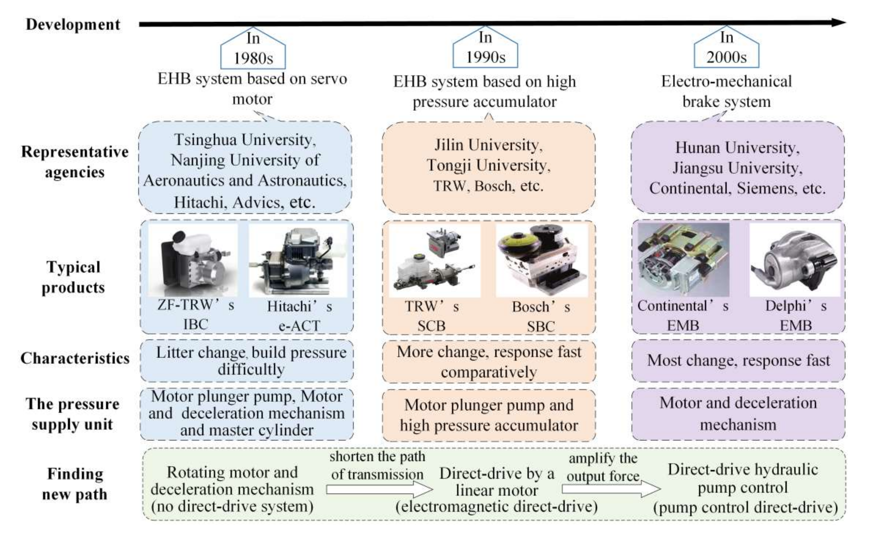
2. Structures of BBW System

The Goodyear company proposed the idea of a BBW system for the first time in 1979, and the Lorrell company successfully completed experimental tests of the electric brake system on an A-10 attack aircraft in 1982, thus opening the first page of the development of BBW System. Various forms of BBW systems were designed during this time. According to the different types of sources and regulations for braking force, it is mainly divided into an electro-hydraulic brake (EHB) system based on a servo motor and an EHB system based on high-pressure accumulator and electro-mechanical brake (EMB) system. The BBW system uses wires to replace parts or all of the brake pipelines, and the controller manipulates the electronic control elements to control the braking force. Essentially, it is an energy transformation system, where the power unit amplifies the output force through hydraulic or mechanical mechanisms [10]. At present, research efforts aim to shorten the response time of the brake and improve the accuracy of the braking control [11]. The structures and characteristics of a typical BBW system are shown in Figure 1.

2.1. Electro-Hydraulic Brake System Based on Servo Motor

In the 1980s, based on the mature automotive ESC system, many researchers designed some schemes of an EHB system based on a servo motor. This system drives the master cylinder piston by increasing the motor’s rated speed and displacing the motor plunger pump or controlling the motor and deceleration mechanism. It realizes the normal operation of the brake system without changing the overall structural arrangement of the brake system [10]. To increase market share, original equipment manufacturers (OEMs) prefer to adopt this kind of solution. Continental’s MK C1 system is a typical motor structure and deceleration mechanism, which makes the master cylinder produce hydraulic pressure, and then the motor rotates and turns the torque into the thrust of linear motion under the controller. This method has a simple principle and is easy to control [18]. Hitachi’s e-ACT system is an electric intelligent brake system. When the driver steps on the brake pedal, the brake master cylinder builds up hydraulic pressure through the pedal push rod and the piston pump and achieves brake [19]. Song designed a hydraulic brake system based on the electronic stability program (ESP), and the arrangement of the system is an X-type circuit. To control the pressure of the four wheels, two symmetrically arranged piston pumps are driven by a motor [20]. Yu applied for a new EHB system structure, which consists of a DC motor, lead screw and the mechanism of gear and pinion. This system produces hydraulic pressure by pushing the plunger of the master cylinder [21]. Wu studied a hydraulic brake system of a dual hydraulic cylinder that can achieve backup when the four wheels lose efficacy and brake through a motor drive the brake master cylinder. The system has small changes and is convenient to arrange [22].

2.2. Electro-Hydraulic Brake System Based on High-Pressure Accumulator

From the 1990s to the early 2000s, motor technology was still immature. To solve the requirements of high pressure and fast flow for brake systems, the EHB system, which uses a high-pressure accumulator as an energy store and energy supply device, was a solution; the system builds up high pressure by the motor plunger pump and saves in it the high-pressure accumulator in advance. The high pressure, which can provide the brake fluid at a faster speed and reduce the response time of the brake, is released when the brake starts [11]. Bosch, Advics and other companies have started to supply relevant products for Mercedes-Benz, General, Ford, Toyota and other OEMs. The electronically controlled braking system of Advics is the earliest EHB system with a high-pressure accumulator. This system cancels the vacuum booster, and the pedal is directly connected to the master cylinder [23]. TRW designed a slip control boost (SCB) brake system based on a high-pressure accumulator; it mainly consists of a new type of brake master cylinder and an electro-hydraulic control unit [14]. The same solution based on high-pressure accumulators and solenoid valves is as follows. Bosch studied a sensotronic brake control (SBC) system, which is a semi-separated structure. The accumulator saves the high-pressure brake fluid, which is provided by the pump; meanwhile, the system obtains the brake effect by releasing the brake fluid to the wheel cylinders [24]. Jin designed an EHB system, and it consists of the simulator of pedal feel, electronic control unit and hydraulic control unit. Jin’s system can achieve three different working conditions by controlling the different states of solenoid valves [25].

2.3. Electro-Mechanical Brake System

In the early 2000s, to further reduce the response time of active braking, shorten the distance of emergency brakes and simplify the brake system, the suppliers of brakes and research institutes began to research some new brake systems, such as EMB. The output torque, which is provided by a motor, is directly transmitted to the friction components of the brake through a mechanism of slowing down and increasing torque, such as a gear deceleration mechanism and a ball screw mechanism, and the friction braking torque is generated [9]. The EMB of Bosch is a form of a two-stage planetary gear deceleration mechanism and ball screw mechanism, in which the motor can be a transverse flux motor or a permanent magnet synchronous motor and transmit torque by gear. This EMB has some advantages, such as its compact structure and good reliability [26]. The Continental’s EMB cleverly integrates the ball screw mechanism and planetary gear deceleration mechanism through the middle-ribbed support tube, the internally ribbed tube and the internally ribbed rotor. Meanwhile, Continental designed the rotor locking device [27]. Siemens studied a booster structure of lever driving by using the lever principle, adjusted the brake gap using a mechanical gap in time mechanism, and measured the position of the push rod using a position sensor, so the pressure control is more accurate [28]. Tsinghua University built a complete text of a bench system of an EMB system based on the direct-drive configuration and designed a torque motor controller [29]. Tongji University designed a model machine of the EMB system based on direct-drive configuration [30]. Li designed an EMB system that also uses a combination of planetary gears and ball screws [31]. Gong designed a new EMB system, which provides braking force for the brake system through a linear motor directly drives the amplification mechanism [32].
Various BBW systems have been proposed, as the traditional brake systems limit the design of most BBW systems. To meet the demands of the market and the reliability, it is very meaningful to improve the performance of the BBW system, simplify the structure of the BBW system and explore a new structure of the BBW system. With the increasingly urgent requirements of high efficiency, energy-saving and a high response performance, “direct-drive” and “near zero drive” provide a new technology route for BBW systems.

3. Design Flow of the BBW System

With the performance requirements of the BBW system improving continuously, the development and application of new types of BBW systems require guidance from an advanced and efficient design flow. From demands analysis to optimization designs, the designers need to adopt a variety of disciplinary knowledge from the overall consideration to make the BBW’s comprehensive index reliability, security, practicability, maintainability and other aspects meet the requirements and achieve better [33]. Among them, the design of key components and the design of a single discipline are two main factors in the design process. The diagram of the design flow is shown in Figure 2.

3.1. The Design of Key Components

3.1.1. The Pressure Supply Unit

The design of the key components mainly revolves around the pressure supply unit and the pressure regulation unit that realize the accurate control of the brake wheel cylinder pressure. The pressure supply unit is the source of the braking force, while the source of the power unit is often a motor. According to the difference in the force amplification mechanism and the motion transformation mechanism, it is mainly divided into mechanical and hydraulic motion mechanisms. The main forms of machinery include a rotating motor combined with the mechanism that slows down and increases torque and the motion transformation mechanism, linear motor, a mechanical amplification mechanism of force, etc. [32]. KI designed an EMB system using electrical actuators, helical gears, etc. The system converts the motor’s rotary motion into linear motion through the helical gear, and the linear motion generates a clamping force between the brake piece and the brake disc [36]. Gong designed a new type of linear actuator based on a linear motor, which provides a driving device for the brake system using the linear motor’s characteristics of linear driving and the lever principle [32]. Han designed an electro-wedge brake system that consists of a motor, worm gears, a caliper and a wedge and generates braking force by controlling electronic actuators and self-excited wedge mechanisms [37]. The type of hydraulic mainly includes motor pump, motor-assisted master cylinders, etc. [38]. Zong studied a general scheme of an EHB system. The source of the EHB system consists of a motor pump and a high-pressure accumulator, and the hydraulic electric pump provides high-pressure brake fluid for the accumulator and continuously accumulates its energy [39]. Shangguan designed an integrated electronic–hydraulic brake system, in which the driving motor drives the ball screw by the deceleration pair gear, and it pushes the piston of the servo master cylinder to build up pressure [38]. Gong designed a direct-drive EHB unit based on an electromagnetic linear actuator. Gong’s unit directly drives an unequal-diameter hydraulic cylinder to provide hydraulic pressure for wheel cylinders by the linear motor [40].

3.1.2. The Pressure Regulation Unit

The pressure regulation unit is a key component in controlling the braking force, and it plays an important role in the realization of active safety, such as ABS, ESP, etc. The EHB system usually uses linear valves, on-off valves and other valve-controlled pressure regulation methods; motor booster master cylinders, motor servo pumps and other pump-controlled pressure regulation methods; and the methods of coordinated pumps and valves [41]. Li controlled the hydraulic pressure of the wheel cylinder with a direct-drive valve that consisted of an electromagnetic linear actuator based on the Halbach permanent magnet array and valve core [42]. Chu studied a current-response characteristic of a high-speed switching electromagnetic valve and a realization method of the accurate control of the brake pressure [43]. According to the command of the brake, Xiong controlled the forward and reverse rotation of a rotating motor to drive a deceleration mechanism, push the main cylinder piston and increase or reduce the pressure [44]. Yao separately controlled a motor pump and a high-speed switching solenoid valve and achieved a rapid response and accurate control of the wheel cylinder’s hydraulic pressure [45]. The EMB system usually controls the forward and reverse movements of a rotary or linear motor to control the clamping force of the brake. Continental applied the patent of an EMB structure, which realizes the brake when the rotating motor is forward and releases the brake in the reverse direction [27]. Gong designed a new brake system based on a linear motor. When the linear motor moves forward, the brake piece is pushed to complete the clamping brake; when the linear motor moves in the reverse direction, the braking force is released [32].

3.2. The Design of Single Discipline

In terms of the designs and analysis methods of brake systems, the research about single-discipline issues is constantly advancing from designing basic structure parameters to analyzing the dynamic performance. In addition, the rise in energy consumption and temperature has gradually attracted the attention of researchers. Iqbal designed a new bilayer multi-pole electromagnetic brake, which was derived from an analytical model of the brake and compared with simulation results by finite element modeling [35]. Wang studied an adaptive dual-loop brake pressure control method to verify the dynamic performance of the system [46]. Li used an adaptive weighted particle swarm optimization algorithm to optimize the nonlinear flow controllability of a solenoid valve, and after optimization, the flow controllability of the solenoid valve increased by 119.7% [47]. He analyzed the effect of system parameters and structure parameters on the energy consumption characteristics of an EHB system [48]. Deng studied the influences of parameters in the friction torque model and analyzed the proportion of the friction torque at each component and the influence of the rotation rate and clamping force on these friction torques [49]. Zhao studied a model based on the overall rise in brake temperature based on the temperature rise and temperature fall models [50]. The brake system is a highly integrated mechanical–electrical–hydraulic system, especially when considering the cross-coupling of the internal electromagnetic field, temperature field, structure field, flow field and other multi-physical field effects. To improve the efficiency of energy transmission, brake systems put forward higher requirements for the effectiveness of the system design flow. Li analyzed the interaction mechanisms and the characteristics of the electromagnetic, fluid and temperature of a double-sided axial permanent-magnet eddy current brake [51].
Considering the dynamic performances of the system, improving the system efficiency and simplifying the system arrangements, the effective design flows of a BBW system of integration for mechanical–electrical systems or mechanical–electrical– hydraulic systems are of great significance to the development of the BBW system.

4. Lower Control Technology of BBW System

The execution control technology of the BBW system is the key to the rapid response and control accuracy of the system. An accurate model, observation of difficult model factors and the effectiveness of control methods are the research hotspots [52]. The development trend of execution control technology is reflected in: identifying the system parameters to improve the accuracy of the model, observing states to obtain the disturbances of a difficult model and combining composite control algorithms with complementary advantages of different algorithms to achieve effective compensation control. The main methods and characteristics of parameters identification, states observation and control methods are shown in Figure 3.

4.1. The Method of Modeling

From the perspective of system modeling, the existence of nonlinear factors, such as dead-zone and friction, in the BBW system and the interference factors, such as modeling and no modeling, make it impossible to obtain accurate parameters of a model. Researchers obtain the parameters of a model with a black box or state observation, which are indirect identification methods. Tao studied a method of dead-zone identification for a proportional directional valve based on the pressure change in the cylinder inflatable chamber [53]. Wu created a LuGre friction model to represent the friction characteristics of the system in the electric-power-assisted braking system and used genetic algorithms to conduct the parameter identification of the LuGre model [22]. Li searched for an optimal solution using the genetic algorithm, considered the hydraulic unit and brake wheel cylinder as a gray box and used the pressure and flow test data to identify the unknown parameters in the ESP system [54]. Jin identified some key parameters of the model using the method of linear regression parameter identification and validated the model of the EHB system with experimental data of a test bench [55]. Zhang constructed an extended state observer to estimate the no modeling dynamics of the test bench system, which improves the modeling accuracy [56]. Ma designed a linear extended state observer to estimate uncertain dynamics [57].

4.2. The Method of Control

An effective strategy for compensation control is a development trend of solving nonlinear problems. Todeschini fully considered the characteristics of the saturation and dead-zone for the hydraulic components and ensured the accuracy of system pressure control by designing a compensation controller [58]. Li studied a brake pressure compensation control method based on the sliding mode control (SMC) algorithm in the electronic booster hydraulic brake system to ensure the vehicle brake safety effectively [59]. Xiong used a chatter compensation method to control the hydraulic pressure of the integrated EHB system, and the method can mitigate the oscillation and low-speed creeping problems caused by friction under different working conditions [60].
From the perspective of control algorithm, the algorithm of traditional control, such as PID control, decoupling control and other methods, and the algorithm of modern control, such as adaptive control, robust control and other methods, are constantly being applied in the field of BBW systems. Zong used a PID control method based on the feedback of brake pressure to help the brake system achieve good hydraulic control effects [39]. Todeschini studied a hybrid position-pressure switching controller that aimed at coping with the highly nonlinear and time-varying nature of the EHB system, which effectively improved the robustness of the brake system to hydraulic nonlinear interference and reduced the influence of valve dead-zone [61]. Xiong designed adaptive sliding mode hydraulic pressure control based on desired state and integral anti-windup compensation, and the controller improved the robustness of the wheel cylinder pressure control [62]. Yang used an SMC method to improve the robustness of an electric booster system, and the brake system has stronger anti-interference [63]. Tanelli studied a nonlinear output feedback control law for active braking control systems, which can effectively improve the stability of a vehicle under braking conditions [64]. Yang adopted a kind of time-sharing control strategy to realize the purpose of independent and accurate hydraulic pressure regulation of each wheel brake cylinder in various brake conditions of a vehicle [65]. Chen designed the hydraulic pressure controller based on fuzzy PI control to improve the robustness of the PI controller [66]. Wang used a closed-loop control method based on the feedback of brake pressure and designed a hydraulic PI controller with gain-scheduling. The distributed EHB system achieved good hydraulic control effects in the full working range [67]. Yu studied an optimized self-adaptive PID controller based on the Taguchi method to adapt the changes of target pressure and brake characteristics and ensured that the pressure could respond rapidly in the early process and track accurately in the later process [68].
Intelligent control methods, such as reinforcement learning and neural networks, are also integrated into the control of the BBW system, especially the application of complex algorithms, which greatly improves the performance of the BBW system. Zhao designed a hydraulic pressure SMC method based on a radial basis function (RBF) neural network. The adaptive law of the RBF neural network adjusted the parameters of the sliding mode controller of the system and achieved accurate control of the hydraulic pressure of the system [69]. Cao studied a controller that combines a neural network and SMC, and the RBF neural network is used to adaptively adjust the switching gain of the sliding mode controller, which effectively reduces the instability of the system and improved the robustness of the system [70]. Yang developed an integrated time-series model based on multivariate deep recurrent neural networks with long short-term memory units for the dynamic estimation of the brake pressure of EVs, which can achieve a more reliable multistep prediction with higher accuracy [71]. Kim designed an application of the brain’s limbic system based on control, and through a genetic algorithm, Kim optimized the control parameters, which improves the control speed, reference tracking and robustness to the disturbance of the system [72].
Deeply researching the coupling effects of various nonlinear factors in the BBW system, designing observation methods for multiple nonlinear factors and creating more accurate control, which considers compensating for various nonlinear factors at the lower execution, are of great significance for improving the response speed and accurate control of the brake system.

5. Upper Coordination Strategy of BBW System

Braking safety and braking energy recovery are two important themes in the research of BBW systems [73]. The design of the BBW system should consider the safety of the vehicle firstly, including the ABS system, to make the vehicle decelerate quickly and the braking force distribution system to make the vehicle maintain the stability of the braking direction. In the case of ensuring the braking safety of the vehicle, the design of the brake system should recover as much braking energy as possible. For example, regenerative braking improves the energy utilization rate of the vehicle. The characteristics of the control strategies and upper coordination strategy are shown in Figure 4.

5.1. The Control Strategy of Anti-Lock Brake System

The ABS system of the vehicle can effectively prevent the wheel lock when the vehicle is braking, so the wheel can make full use of the road friction coefficient to reduce the braking distance to ensure the direction stability of the vehicle and the safety of the vehicle during braking [74]. The strategy of logic threshold control is widely used in ABS; the idea is to adjust the wheel pressure according to the current wheel acceleration. The wheel brake pressure reduces when the wheel speed decelerates rapidly, and the vehicle brake pressure increases when the wheel speed is restored [75]. The ABS strategy based on the logic threshold has little dependence on the vehicle model and parameter identification and has simple logic but cumbersome calibration. Combining the logic threshold control and fuzzy rules, the ABS strategy based on fuzzy control is further studied [76]. The PID control makes a feedback adjustment according to the wheel slip ratio, which effectively reduces the calibration process compared with the logic threshold and the regular strategy. In addition, SMC, model predictive control and other strategies have been studied in ABS. This type of method takes wheel slip as the primary target of control and heavily depends on the longitudinal speed of the vehicle [77]. Tang studied a fractional-order SMC for ABS to regulate the slip to a desired value, which combines a sliding mode controller with fractional-order dynamics to control the wheel slip ratio, deal with the uncertainties in the ABS system and track the desired slip faster [78]. Guo designed a sliding mode controller based on the exponential reaching law for the ABS to maintain the optimal slip value, and a fuzzy logic controller optimizes the parameters of the reaching law [79]. To achieve accurate control of the wheel slip ratio, the brake actuator is also required to provide an accurate braking response. This type of method is mostly used in BBW systems and requires additional sensors to accurately measure the speed of the vehicle. However, it has not been widely used in actual products. In the future, ABS will develop towards a trend of more compact structures, more diversified control methods and continuous expansion of the system’s functions.
The braking system of EV is composed of two parts: mechanical braking system and regenerative braking system—composite braking for short [80]. Composite braking needs to achieve certain goals, including meeting the driver’s demand for braking force, maximizing braking energy recovery, maximizing the adhesion coefficient, meeting the driver’s demand of braking comfort, etc. Its basic starting point is to maximize the recovery of braking energy as far as possible while ensuring the dynamic performance of braking [81].

5.2. The Control Strategy of Braking Force Distribution

The reasonable distribution of the mechanical friction braking force and motor braking force can make the braking force full play, shorten the distance of the brake system and improve the stability of the brake. Combining with ABS can improve braking stability and ensure the safety and comfort of the brake [82]. The traditional methods of braking force distribution distribute according to a predetermined ratio, such as the ideal braking force distribution, fixed ratio braking force distribution, etc. The fixed ratio braking force distribution is relatively simple. Gao conducted a simulation analysis on an EV with a fixed ratio braking force distribution strategy, which improves the stability of the brake system [83]. The braking force distribution strategy based on model predictive control refers to the use of the model predictive theory as an effective method in the braking process. Xu presented a novel braking torque distribution strategy based on model prediction control theory for EVs with four in-wheel motors, which can distribute the braking torque and the motor braking torque effectively [84]. The braking force distribution strategy based on an intelligent algorithm refers to the use of a certain intelligent algorithm to deal with the multi-objective and multi-constrained nonlinear problem of regenerative braking and make the coordination braking control transform braking force distribution problem. Li studied a braking force distribution strategy in the fuzzy area based on fuzzy rules for an electromechanical composite braking system of EVs, which improves the braking performance [85]. Wang explored an optimized allocation method of braking force under multi-objectives and multi-constraint conditions to find the optimal distribution ratios of front and rear axles, regenerative braking and hydraulic braking [86].

5.3. The Control Strategy of Regenerative Braking

Regenerative braking can recycle the energy loss in the braking process, and it improves energy utilization, achieves more accurate braking control and increases the driving range of EVs [87]. At present, regenerative braking control strategies include ideal braking force distribution and optimal braking energy recovery. The ideal braking force distribution can make full use of road adhesion conditions and keep the stability of braking. Ma studied an improved braking energy recovery strategy based on ideal braking force distribution for the regenerative braking system of a small four-wheel-drive EV, which is able to effectively achieve the regenerative braking function under different braking conditions [88]. Zhao designed an ideal braking power distribution strategy based on the economic commission for Europe regulation, and the braking energy can be recovered effectively [89]. The optimal braking energy recovery control strategy maximizes the energy recovery theoretically. Liu studied an optimal regenerative braking control strategy, which can obtain the maximum braking torque through the dynamic analysis of the relationship between motor torque performance and automobile braking force demand torque, further maximizing the braking energy and ensuring braking safety [90]. Guo studied an optimal control strategy of regenerative braking energy for EVs, and the optimal braking rate control can better recover braking energy [91]. Meanwhile, intelligent control is also applied to the regenerative braking control strategy. Xu studied a hierarchical controller for the hybrid electrical vehicle. The braking mode switching uses the rule-based control strategy, and the optimal efficiency control for the system uses the neural network algorithm, which can improve the braking performance [92].

5.4. The Control Strategy of Intelligent Coordination

While braking, the upper coordination control strategy realizes the coordination control between different braking control strategies to ensure the safety and maximum energy recovery in the braking process [93]. Many scholars introduce the intelligent control algorithm into the upper coordination control of the brake system. Pei took coordination control of EHB as a global distribution problem of two braking torques—hydraulic and regenerative—and used the genetic algorithm under different braking conditions to achieve the optimal distribution coefficients. This strategy has better performance of energy regeneration and braking stability than I-curve distribution [94]. Shetty studied an optimal brake force distribution problem using an artificial-neural-network-based methodology to maximize the available energy recovery while following the rules for stability [95]. Bao established a coordination control strategy using a BP neural network and fuzzy PID for the composite brake, which improves the braking performance and shorten the braking time [96].
The braking force distribution based on an intelligent algorithm can better handle the nonlinear problem of braking force distribution during the braking process than the traditional rule-based braking force distribution strategy. The optimal braking energy recovery can obtain the maximum braking energy recovery, but the stability needs to be further improved. The more intelligent algorithm, considering the braking energy recovery efficiency and braking stability, will become the key research topic of the upper coordination strategy and is of great significance to coordinate the braking safety and energy recovery for EVs.

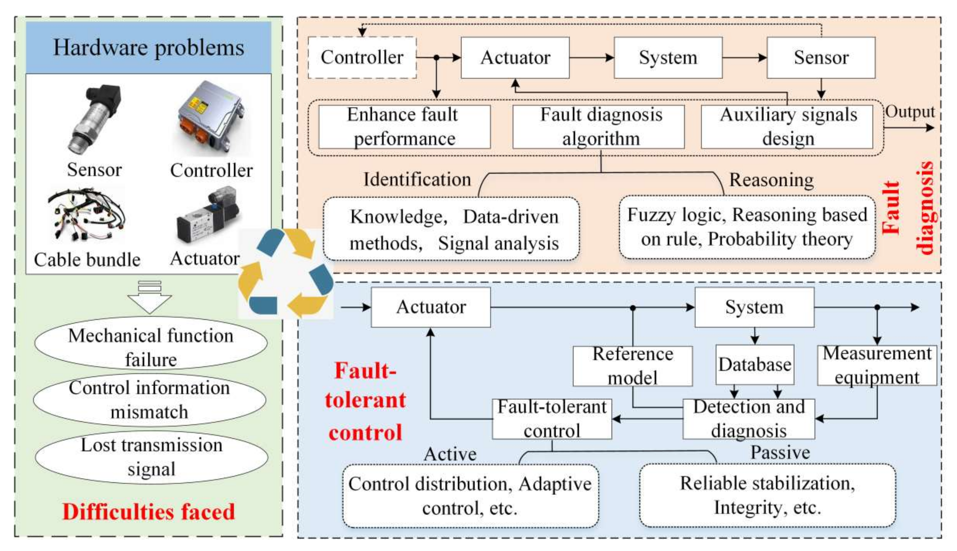
6. Fault-Tolerant Control Technology of BBW System

The safety of the BBW system is a key point of people’s attention. Benz’s brake fault recall and Tesla’s brake fault event further illustrate the importance of system reliability and fault-tolerant control (FTC) [97]. The difficulties, which the brake fault faced, may happen in actuators, sensors, controllers, etc. Compared with sensors, controllers, etc., the actuator fault is the main challenge that the brake system faces. When some actuators fault, the vehicle may lose its effectiveness, and the fault will be unable to meet the targets of movement control. Moreover, the ability of brake will lose efficacy, the safety of the brake will decline and other potential problems and risks may arise. Effective fault diagnosis and FTC are a method to solve the brake fault, and the characteristics and solutions of the brake fault are shown in Figure 5.

6.1. The Method of Fault Diagnosis

Effective identification and reasoning for the brake systems of uncertain failure problems are a difficult point in fault diagnosis and a basis of FTC [98]. The knowledge set of fault diagnosis based on knowledge is difficult to be accurate and complete. The fault diagnosis methods based on signal analysis directly use the input and output signals to analyze and handle through the auto-regressive moving average model, correlation function analysis method, spectrum analysis method, etc. [99]. The most important thing to solve the problem of uncertainty is how to obtain the reasoning process of unknown information through sample information. Common methods include fuzzy logic, uncertainty problem deterministic, probability theory, reasoning based on rule, etc. [100,101]. Kim recognized fault identification as performance degradation and expressed by the gains of each actuator [102]. Wang studied an active fault diagnosis approach to explicitly isolate and evaluate the fault, and the control efforts of all the wheels are redistributed to relieve the torque demand on the fault wheel [103]. The method based on the model of analysis achieves the fault diagnosis by estimating the changes in the internal parameters of the brake system. Zong utilized the extended Kalman filter algorithm in the fault detection module to estimate the in-wheel motor parameters, which could detect parameter variations that are caused by the wheel motor fault [104]. With the rapid development of sensor technology and computer technology, the fault diagnosis methods based on Intelligence are gradually applied to the brake system. Chen studied a new prediction model of a grey support vector machine, optimized the relevant initialization parameters of the grey support vector machine through particle swarm optimization and used the optimized model to diagnose and predict brake fault [105]. In the future, researching the accuracy of faults is an important direction for the development of fault-tolerant problems in brake systems.

6.2. The Method of Fault-Tolerant Control

FTC is a control method that can still ensure the system’s stability and maintain a good performance when the components of the control system lose efficacy. According to whether based on the fault detection and diagnosis mechanism, the FTC can be divided into active FTC and passive FTC [106]. The active FTC automatically adjusts the controller parameters according to the information of fault diagnosis and gives corresponding optimal solutions for different fault types and fault levels. The main methods include control distribution, robust control and adaptive control. Kim presented a fault-tolerant brake torque controller and constructed adaptive schemes to achieve the FTC of brake [102]. The FTC methods based on control distribution do not change the structure of the upper controller. The distribution method is used to distribute in each actuator after obtaining the virtual control input. Zhang designed integral sliding mode fault-tolerant control of the BBW system, which improved the sensitivity of the controller to the fault, realized the automatic offline and redistribution of the fault actuator and ensured the direction stability of the vehicle through the design of the weight matrix of the online control distribution method [107]. According to prior knowledge, the passive FTC fully considers possible faults in the design of control to realize fault tolerance control. Wang designed an adaptive control-based passive FTC and showed the effectiveness of the FTC approaches in various driving scenarios [103].
Researchers have achieved good results in the research of fault diagnosis and FTC of the brake system. Among them, effectively overcoming the probability of faults and accurately realizing the online diagnosis, prediction and reliable FTC after faults are of great significance to the safety of vehicles.

7. A Trend of BBW System

With the development of materials, computers, and electronic technology, the direct-drive technology and near zero-drive technology have been developed rapidly and widely used in all-electric aircrafts, maglev trains, vehicles and other means of transportation [108]. They have the advantages of fast response time, high positioning accuracy, and high power density. The use of direct-drive actuators can bring many benefits in high-speed, high-precision movements, such as reducing the weight and size of the system, lowering maintenance cost and increasing reliability, and the direct-drive actuators are gradually occupying the market of the non-direct-drive control execution.
Our team designed a high power density moving-coil electromagnetic linear actuator, which is composed of some components such as external yoke, inner yoke, permanent magnets, electromagnetic coil and coil skeleton, etc. Our team applied the direct-drive technology to an automatic transmission, electronic injection device, brake system, etc., the theory analysis and application of direct-drive technology are shown in Figure 6.
We optimized the structure by variable weight coefficient and analyzed the performance of the electromagnetic linear actuator [109,110,111]. The shift mechanism of automatic transmission is based on the electromagnetic linear actuator, which improves the shift quality and shortens the power interruption time during the shift process [109]. Moreover, the team of Akhondi designed a new type of electric power steering system based on a tubular linear motor with an interior permanent magnet, which improves the time-handling performance and safety performance of steering [112]. The team of Lee designed a new type of active suspension actuator system by using a linear pump control-based hydraulic system, which improves the vehicle dynamics using a cost-effective actuation system significantly [113]. The direct-drive technology provides a new scheme for higher-quality regulation of the X-by-wire system. At the same time, intelligent control technology, as a research hotspot in the field of artificial intelligence, provides a new idea for highly efficient and highly reliable control of the direct-drive system.
With the demand for electric, intelligent, high-efficiency and energy-saving BBW systems, the intelligent direct-drive BBW system based on advanced direct-driven technology and intelligent control technology will become a potential research direction for the BBW system in the future. Direct-drive technology is mainly applied to the execution device of the BBW system. The intelligent control technology can be applied to lower control technology and the upper coordination strategy of the BBW system. The intelligent direct-drive BBW system has the advantages of high response, high precision, high reliability and others. It is of great significance to enrich the theory system of the complex mechanical–electrical–hydraulic system.

8. Conclusions

Through the analysis of the current research status of BBW systems and intelligent control technology for vehicles, the current development goal of the BBW system is as follows: A more efficient, energy-saving and responsive structure. More accurate control that considers compensating for various nonlinear factors at the lower execution. More intelligent at the upper control strategy while having fault-tolerant abilities.
In the future, an intelligent direct-driving BBW system will be a research direction, as it takes high-efficiency and energy-saving as a foothold and aims at breaking through dynamic response, control accuracy and fault-tolerant abilities.

Author Contributions

All authors conceived the paper and designed the review study. D.L. conducted the search and analysis of the related literature, drafted the paper and thoroughly revised the manuscript; C.T. collected and analyzed the references about the control technology of lower execution; W.G. collected and analyzed the references about the control technology of upper coordination; J.C. collected and analyzed the references about fault-tolerant control technology; C.G. collected and analyzed the references about direct-drive technology, and checked the paper format; X.C. modified and checked the paper format. All authors have read and agreed to the published version of the manuscript.

Funding

This review was funded in part by the National Natural Science Foundation of China (Grant No. 51905319; Grant No. 51975341; Grant No. 51875326), in part by the China Postdoctoral Science Foundation (Grant No. 2021M691984); in part by the Technology Development Fund Project of the Centre Guides Local Government of Shandong Province (YDZX202037000011 77); in part by the Young Technology Talent Supporting Project of Shandong Province (SDAST202 1qt20).

Institutional Review Board Statement

Not applicable.

Informed Consent Statement

Not applicable.

Data Availability Statement

No new data were created or analyzed in this study. Data sharing is not applicable to this article.

Conflicts of Interest

The authors declare no conflict of interest.

References

  1. Zong, C.; Li, G.; Zheng, H.; He, L.; Zhang, Z. Study process and outlook of chassis control technology for X-by-wire automobile. China J. Highw. Transp. 2013, 26, 160–176. [Google Scholar]
  2. Zhao, X.; Ye, Y.; Ma, J.; Shi, P.; Chen, H. Construction of electric vehicle driving cycle for studying electric vehicle energy consumption and equivalent emissions. Environ. Sci. Pollut. Res. 2020, 27, 37395–37409. [Google Scholar] [CrossRef] [PubMed]
  3. Kumar, R.; Alok, K. Adoption of electric vehicle: A literature review and prospects for sustainability. J. Clean. Prod. 2020, 253, 119911. [Google Scholar] [CrossRef]
  4. Yu, Z.; Han, W.; Xu, S.; Xiong, L. Review on hydraulic pressure control of electro-hydraulic brake system. J. Mech. Eng. 2017, 53, 1–15. [Google Scholar] [CrossRef]
  5. Editorial Department of China Journal of Highway and Transport. Review on China’s automotive engineering research progress: 2017. China J. Highw. Transp. 2017, 30, 1–197. [Google Scholar]
  6. Chen, H.; Gong, X.; Hu, Y.; Liu, Q.; Gao, B.; Guo, H. Automotive control: The state of the art and perspective. Acta Autom. Sin. 2013, 39, 322–346. [Google Scholar] [CrossRef]
  7. Zhang, J.; Lv, C.; Li, Y. Hybrid propulsion and hybrid braking technologies of electrified vehicles: Status and prospect. J. Automot. Saf. Energy 2014, 5, 209–223. [Google Scholar]
  8. Li, L.; Wang, X.; Cheng, S.; Chen, X.; Huang, C.; Ping, X.; Wei, L. Technologies of control-by-wire and drnamic domain control for automotive chassis. J. Automot. Saf. Energy 2020, 11, 143–160. [Google Scholar]
  9. Gong, X.; Ge, W.; Yan, J.; Zhang, Y.; Gongye, X. Review on the development, control method and application prospect of brake-by-wire actuator. Actuators 2020, 9, 15. [Google Scholar] [CrossRef] [Green Version]
  10. Meng, B.; Yang, F.; Liu, J.; Wang, Y. A survey of brake-by-wire system for intelligent connected electric vehicles. IEEE Access 2020, 8, 225424–225436. [Google Scholar] [CrossRef]
  11. He, R.; Feng, H. Research and development of autonomous emergency brake (AEB) technology. J. Automot. Saf. Energy 2019, 10, 1. [Google Scholar]
  12. Braking Control Systems: Integrated Brake Control (IBC). Available online: https://www.zf.com/products/en/cars/products_%20316%2080.html (accessed on 13 March 2019).
  13. Ohtani, Y.; Innami, T.; Obata, T.; Yamaguchi, T. Development of an electrically-driven intelligent brake unit. SAE Tech. Pap. Ser. 2011, 1, 572. [Google Scholar]
  14. Savitski, D.; Ivanov, V.; Schleinin, D.; Augsburg, K.; Putz, T.; Lee, C. Advanced control functions of decoupled electro-hydraulic brake system. In Proceedings of the IEEE 14th International Workshop on Advanced Motion Control (AMC), Auckland, New Zealand, 22–24 April 2016; pp. 310–317. [Google Scholar]
  15. Nakata, D.; Okano, T.; Fukasawa, T. Brake Apparatus Brake Control Unit and Brake Control Method. U.S. Patent 8303046B2, 6 August 2012. [Google Scholar]
  16. Jungbecker, J.; Schmitt, S.; Hoffmann, O. Actuating Unit for An Electromechanically Actuated Disc Brake. U.S. Patent 6752249B1, 17 February 2004. [Google Scholar]
  17. Lvarez, B.; Longuemare, P.; Heck, T.W. Electromechanical Brake and Method for Controlling Same. EUR. Patent 1456555B1, 27 February 2001. [Google Scholar]
  18. Wang, L. MK C1: Braking made simple. Automot. Obs. 2019, 6, 106–107. [Google Scholar]
  19. Fujiki, N.; Koike, Y.; Ito, Y.; Suzuki, G.; Gotoh, S.; Ohtani, Y.; Yamagucki, T. Development of an electrically-driven intelligent brake system for EV. SAE Tech. Pap. Ser. 2011, 4, 399–405. [Google Scholar]
  20. Wang, W. Dynamics Analysis on Electronic Stability Control system Hydraulic Control Unit and Establishing an Integrated Simulation Platform; Tsinghua University: Beijing, China, 2011. [Google Scholar]
  21. Yu, Z.; Huang, J.; Jian, C.; Xiong, L. An electronic Hydraulic Brake System Driven by a Motor. CN Patent 204567652, 19 August 2015. [Google Scholar]
  22. He, R.; Wu, J.; Gao, J. Modeling and compensation control for friction in vehicle power assisted braking system. Automot. Eng. 2017, 39, 683–688. [Google Scholar]
  23. Nakamura, E.; Soga, M.; Sakai, A.; Otomo, A.; Kobayashi, T. Development of electronically controlled brake system for hybrid vehicle. SAE Tech. Pap. Ser. 2002, 1, 300. [Google Scholar]
  24. Cai, B. Structural principle analysis of SBC braking system on benz. Auto Electric Parts 2012, 9, 13–16. [Google Scholar]
  25. Zhang, H. Analyse and Control of Electro Hydraulic Braking System for Vehicle; Nanjing University of Aeronautics and Astronautics: Nanjing, China, 2013. [Google Scholar]
  26. Keller, F. Electromagnetic Wheel Brake Device. U.S. Patent 6536561, 25 January 2003. [Google Scholar]
  27. Rieth, P.; Schwarz, R.; Kranlich, H. Actuating Unit for an Electromechanically Operable Disc Brake. U.S. Patent 6405836, 24 June 2002. [Google Scholar]
  28. Lin, Z. Siemens VDO electronic wedge brake. Shanghai Auto 2007, 5, 38–40. [Google Scholar]
  29. Song, J.; Wang, H.; Liu, G. The Electro-Mechanical Brake of Connecting Rod. CN Patent 2895873Y, 4 December 2007. [Google Scholar]
  30. Shen, C.; Wang, J.; Lin, Y. Study on brake actuator of electro-mechanical braking System. Trans. Chin. Soc. Agric. Mach. 2007, 38, 30–33. [Google Scholar]
  31. Li, J.; Yang, K.; Tan, S. The Electro-Mechanical Brake Actuator of Using in Vehicle. CN Patent 201212535Y, 15 November 2009. [Google Scholar]
  32. Xiao, F.; Gong, X.; Lu, Z.; Qian, L.; Zhang, Y.; Wang, L. Design and control of new brake-by-wire actuator for vehicle based on linear motor and lever mechanism. IEEE Access 2021, 9, 95832–95842. [Google Scholar] [CrossRef]
  33. Liao, Z.; Bai, X.; Li, Y.; Deng, X.; Sun, J. Design, modeling, and verification of a test bench for braking simulation of 1/4 vehicle. Proc. Inst. Mech. Eng. Part D J. Automob. Eng. 2020, 234, 1425–1441. [Google Scholar] [CrossRef]
  34. Zhuo, Z.; Li, Z. Design and simulation of a micro thrust solenoid valve nozzle based on CFD&DOE optimization analysis. J. Phys. Conf. Ser. 2021, 1786, 12008. [Google Scholar]
  35. Iqbal, H.; Yi, B. Design of a new bilayer multipole electromagnetic brake system for a haptic interface. Appl. Sci. 2019, 9, 5394. [Google Scholar] [CrossRef] [Green Version]
  36. Ki, Y.; Lee, K.; Cheon, J.; Ahn, H. Design and implementation of a new clamping force estimator in electro-mechanical brake systems. Int. J. Automot. Technol. 2013, 14, 739–745. [Google Scholar] [CrossRef]
  37. Han, K.; Kim, M.; Huh, K. Modeling and control of an electronic wedge brake. Proc. Inst. Mech. Eng. Part. C J. Mech. Eng. Sci. 2012, 226, 2440–2455. [Google Scholar] [CrossRef]
  38. Shangguan, W.; Liang, T.; Jiang, K.; Tang, W. Modeling and pressure control of integrated electro-hydraulic brake system. J. Beijing Inst. Technol. 2019, 39, 413–418. [Google Scholar]
  39. Mai, L.; Zhang, J.; Zong, C.; Zheng, H.; Guo, L. Vehicle stability control based on electronic hydraulic brake system. J. Jilin Univ. Eng. Technol. Ed. 2010, 40, 607–613. [Google Scholar]
  40. Gong, X.; Chang, S.; Jiang, L.; Li, X. A novel brake-by-wire unit and control system for electric vehicle. J. Shanghai Jiao Tong Univ. 2016, 50, 395–400. [Google Scholar]
  41. Li, Y.; Jin, Z.; Wang, X.; Zhang, X. Dynamic analysis and control of the wire-controlled hydraulic braking system for heavy vehicles. J. Dyn. Control 2021, 19, 15–21. [Google Scholar]
  42. Li, B.; Li, D.; Ge, W.; Tan, C.; Lu, J.; Song, A. Precision control of hydraulic pressure in fast-response brake-by-wire system based on direct-drive valve. China J. Highw. Transp. 2021, 34, 121–132. [Google Scholar]
  43. Chu, L.; Wang, Y.; Qi, F.; Zhang, Y. Control method of inlet vales for brake pressure fine regulation. J. Jilin Univ. Eng. Technol. Ed. 2013, 43, 564–570. [Google Scholar]
  44. Xiong, L.; Han, W.; Yu, Z.; Li, H. Pressure precisely control of master cylinder on integrated-electrohydraulic brake system considering the critical nonlinear. J. Mech. Eng. 2019, 55, 117–126. [Google Scholar]
  45. Yao, Y. Simulation and Experiment Research on Electro-Hydraulic Brake System; Wuhan University of Technology: Wuhan, China, 2014. [Google Scholar]
  46. Wang, X.; Wu, X.; Cheng, S.; Shi, J.; Ping, X.; Yue, W. Design and experiment of control architecture and adaptive dual-loop controller for brake-by-wire system with an electric booster. IEEE Trans. Transp. Electrif. 2020, 6, 1236–1252. [Google Scholar] [CrossRef]
  47. Li, J.; Ding, M.; Huang, J.; Huang, Z. Evaluation and optimization of the nonlinear flow controllability of on-off solenoid valve. J. Jilin Univ. Eng. Technol. Ed. 2019, 49, 325–335. [Google Scholar]
  48. Hu, D.; He, R.; Xu, X.; Yi, F. Analysis on influencing factors of energy consumption characteristics of electronic hydraulic braking system. J. Beijing Inst. Technol. 2018, 38, 261–266. [Google Scholar]
  49. Xia, L.; Deng, Z. Calculation and analysis of friction torque and energy dissipation of electromechanical brake actuator. J. Hunan Univ. 2018, 45, 48–56. [Google Scholar]
  50. Zhao, X.; Yu, Q.; Yuan, X.; Shi, P. A research on the brake temperature rise model of heavy truck running on long downhill. Automot. Eng. 2015, 37, 472–475. [Google Scholar]
  51. Jin, Y.; Pan, D.; Sun, Z.; Zou, Z.; Li, L. Multi-physics simulation analysis of axial permanent magnet eddy current brake. Proc. CSEE 2020, 40, 7469–7480. [Google Scholar]
  52. Lin, H.; Zhuo, G. Electro-hydraulic brake system model identification. J. Jilin Univ. Eng. Technol. Ed. 2011, 41, 70–73. [Google Scholar]
  53. Meng, F.; Tao, G.; Wang, B.; Tao, J.; Chen, H. Identification and control of friction parameters and dead zone parameters of pneumatic servo system. J. Cent. South. Univ. Nat. Sci. Ed. 2018, 49, 2700–2708. [Google Scholar]
  54. Zhang, J.; Li, J. Parameter identification of automotive ESP hydraulic system based on genetic algorithm. Trans. Chin. Soc. Agric. Mach. 2015, 46, 308–313. [Google Scholar]
  55. Jin, Z.; Guo, L.; Shi, R.; Zhao, Y.; Shi, Z. Experimental study on dynamic characteristics of electro hydraulic brake system for vehicle. J. Mech. Eng. 2012, 48, 127–132. [Google Scholar] [CrossRef]
  56. Ma, R.; Wang, L.; Zhang, J.; He, C. Sliding mode active disturbance rejection control for dynamic load emulation of the electric braking system. Automot. Eng. 2020, 42, 141–148. [Google Scholar]
  57. Zheng, Y.; Ma, D.; Yao, J.; Hu, J. Linear active disturbance rejection control for two-axis coupling position servo system of rocket launcher. Acta Armamentarii 2015, 36, 987–993. [Google Scholar]
  58. Todeschini, F.; Formentin, S.; Panzani, G.; Corno, M.; Savaresi, S.M.; Zaccarian, L. Nonlinear pressure control for BBW systems via dead-zone and antiwindup compensation. IEEE Trans. Control. Syst. Technol. 2015, 24, 1419–1431. [Google Scholar] [CrossRef]
  59. Zhang, L.; Yuan, X.; Peng, Y.; Li, S. Hydraulic compensation control of distributed drive electric vehicle with regenerative braking failure. China J. Highw. Transp. 2020, 33, 31–41. [Google Scholar]
  60. Xiong, L.; Xu, S.; Yu, Z. Optimization of hydraulic pressure control system of integrated electro-hydraulic brake system based on chatter-compensation. J. Mech. Eng. 2016, 52, 100–106. [Google Scholar] [CrossRef]
  61. Todeschini, F.; Corno, M.; Panzani, G.; Savaresi, S. Adaptive position–pressure control of a brake by wire actuator for sport motorcycles. Eur. J. Control. 2014, 20, 79–86. [Google Scholar] [CrossRef]
  62. Xiong, L.; Han, W.; Yu, Z. Adaptive sliding mode pressure control for an electro-hydraulic brake system via desired-state and integral-antiwindup compensation. Mechatronics 2020, 68, 102359. [Google Scholar] [CrossRef]
  63. Yang, I.; Choi, K.; Huh, K. Development of an electric booster system using sliding mode control for improved braking performance. Int. J. Automot. Technol. 2012, 13, 1005–1011. [Google Scholar] [CrossRef]
  64. Tanelli, M.; Astolfi, A.; Savaresi, S. Robust nonlinear output feedback control for brake by wire control systems. Automatica 2008, 44, 1078–1087. [Google Scholar] [CrossRef]
  65. Yang, X.; Li, J.; Miao, H.; Shi, Z. Hydraulic pressure control and parameter optimization of integrated electro-hydraulic brake system. SAE Tech. Pap. Ser. 2017, 1, 2516. [Google Scholar]
  66. Chen, Q.; Shao, H.; Liu, Y.; Wang, N.; Shu, Q. Hydraulic-pressure-following control of an electronic hydraulic brake system based on a fuzzy proportional and integral controller. Eng. Appl. Comput. Fluid Mech. 2020, 14, 1228–1236. [Google Scholar] [CrossRef]
  67. Wang, Z.; Yu, L.; Wang, Y.; Song, J. Hydraulic control of actuator of distributed electro-hydraulic braking system. J. Tsinghua Univ. 2013, 53, 1464–1469. [Google Scholar]
  68. Yu, Z.; Wang, J.; Xiong, L.; Xu, S. Hydraulic pressure control of electro-hydraulic brake system. Control. Theory Appl. 2016, 33, 897–902. [Google Scholar] [CrossRef]
  69. Zhao, J.; Deng, Z.; Zhu, B.; Chang, T.; Chen, Z. Sliding mode control based on RBF network for hydraulic pressure in electric power-assisted brake system. J. Mech. Eng. 2020, 56, 106–114. [Google Scholar]
  70. Cao, J.B.; Zhu, X.L.; Jiang, H.; Cao, B. Simulation research on neural network sliding mode control of energy-regenerative braking of electric vehicle. Appl. Mech. Mater. 2010, 37, 1187–1190. [Google Scholar] [CrossRef]
  71. Yang, X.; Chen, L. Dynamic state estimation for the advanced brake system of electric vehicles by using deep recurrent neural networks. IEEE Trans. Ind. Electron. 2019, 67, 9536–9547. [Google Scholar]
  72. Kim, C.; Kim, Y.; Kwon, O.; Seo, J.; Lee, D.; Yi, H. An application of the brain limbic system: Based control to the electromechanical brake system. Adv. Mech. Eng. 2018, 10, 1687814018755215. [Google Scholar] [CrossRef] [Green Version]
  73. Zhang, Z.; Lv, C.; Li, Y.; Gou, J.; He, C. Status quo and prospect of regenerative braking technology in electric cars. Automot. Eng. 2014, 36, 911–918. [Google Scholar]
  74. Wang, Z.; Ding, X.; Zhang, L. Overview on key technologies of acceleration slip regulation for four-wheel-independently- actuated electric vehicles. J. Mech. Eng. 2019, 55, 99–120. [Google Scholar]
  75. Wang, Z.; Yu, L.; Song, J. The status quo of research on vehicle wheel slip control based on brake system. Automot. Eng. 2014, 36, 81–87. [Google Scholar]
  76. Yu, Z.; Feng, Y.; Xiong, L. Review on vehicle dynamics control of distributed drive electric vehicle. J. Mech. Eng. 2013, 49, 105–114. [Google Scholar] [CrossRef]
  77. Liang, Y. Technical research on anti-lock braking system of automobile. Int. Combust. Eng. Parts 2019, 12, 3–4. [Google Scholar]
  78. Tang, Y.; Zhang, X.; Zhang, D.; Zhao, G.; Guan, X. Fractional order sliding mode controller design for antilock braking systems. Neurocomputing 2013, 111, 122–130. [Google Scholar] [CrossRef]
  79. Guo, J.; Jian, X.; Lin, G. Performance evaluation of an anti-lock braking system for electric vehicles with a fuzzy sliding mode controller. Energies 2014, 7, 6459–6476. [Google Scholar] [CrossRef] [Green Version]
  80. He, R.; Liu, X.; Liu, C. Research progress in electromagnetic-hydraulic hybrid brake technology. China J. Highw. Transp. 2014, 27, 109–119. [Google Scholar]
  81. Xiong, L.; Qian, C.; Yu, Z. Review on composite braking system of electric vehicle. Automob. Technol. 2015, 1, 1–8. [Google Scholar]
  82. Zou, Y.; Guo, N.; Zhang, X.; Yin, X.; Zhou, L. Review of allocation control for distributed-drive electric vehicle. China J. Highw. Transp. 2021, 34, 1–25. [Google Scholar]
  83. Gao, Y.; Chen, L.; Ehsani, M. Investigation of the effectiveness of regenerative braking for EV and HEV. SAE Tech. Pap. Ser. 1999, 1, 2910. [Google Scholar]
  84. Xu, W.; Chen, H.; Zhao, H.; Ren, B. Torque optimization control for electric vehicles with four in-wheel motors equipped with regenerative braking system. Mechatronics 2019, 57, 95–108. [Google Scholar] [CrossRef]
  85. Wang, J.; Pan, C.; Chen, L.; Li, Z.; Fang, E.; Lin, J. The strategy of braking force distribution for electromechanical composite braking system based on fuzzy rule. J. Chongqing Univ. Technol. 2021, 35, 66–72+82. [Google Scholar]
  86. Wang, C.; Zhao, W.; Li, W. Braking sense consistency strategy of electro-Hydraulic composite braking system. Mech. Syst. Signal. Processing 2018, 109, 196–219. [Google Scholar] [CrossRef]
  87. Ma, S.; Zhang, L.; Ma, Y.; Huang, X.; Zhang, X. Review on regenerative braking energy recovery. Automot. Dig. 2021, 547, 19–26. [Google Scholar]
  88. Ma, Z.; Sun, D. Energy recovery strategy based on ideal braking force distribution for regenerative braking system of a four- wheel drive electric vehicle. IEEE Access 2020, 8, 136234–136242. [Google Scholar] [CrossRef]
  89. Zhao, Z.; Zhang, J.; Wu, X.; Yang, J. Electro-hydraulic series compound braking control for 4WD HEV using ABS. China J. Highw. Transp. 2015, 28, 124–133. [Google Scholar]
  90. Liu, X.; Wang, H.; He, Y.; Zheng, X.; Zeng, G. Regenerative braking control strategy based on optimal energy recovery. Auto Time 2018, 294, 51–52. [Google Scholar]
  91. Guo, J.; Dong, H.; Sheng, W.; Tu, C. Optimum control strategy of regenerative braking energy for electric vehicle. J. Jiangsu Univ. Nat. Sci. Ed. 2018, 39, 132–138. [Google Scholar]
  92. Xu, Q.; Wang, F.; Zhang, X. Research on the efficiency optimization control of the regenerative braking system of hybrid electrical vehicle based on electrical variable transmission. IEEE Access 2019, 7, 116823–116834. [Google Scholar] [CrossRef]
  93. Zhao, S.; Li, Y.; Yu, Q. Vehicle stability control based on chassis multiple subsystem coordinated control. J. Traffic Transp. Eng. 2015, 15, 77–85. [Google Scholar]
  94. Pei, X.; Pan, H.; Chen, Z.; Guo, X.; Yang, B. Coordinated control strategy of electro-hydraulic braking for energy regeneration. Control Eng. Pract. 2020, 96, 104324. [Google Scholar] [CrossRef]
  95. Shetty, S.; Karabasoglu, O. Regenerative braking control strategy for hybrid and electric vehicles using artificial neural networks. Int. Conf. Eng. Appl. Neural Netw. 2014, 459, 103–112. [Google Scholar]
  96. Bao, J.; Ji, Y.; Yin, Y.; Huang, S. Braking performance and constant torque controlling of frictional-magnetic compound brake. J. Mech. Eng. 2019, 55, 156–165. [Google Scholar] [CrossRef]
  97. Chen, Q.; Yao, Z.; Qadeer, A.; Chen, W.; Fan, H. Design and verification of fault diagnosis and identification system for automotive anti-lock braking system based on structural analysis method. Automot. Eng. 2018, 40, 1354–1363. [Google Scholar]
  98. Xu, K.; Luo, Y.; Yang, Y.; Xu, G. Review on state perception and control for distributed drive electric vehicles. J. Mech. Eng. 2019, 55, 60–79. [Google Scholar]
  99. Chen, Z.; Hu, Y.; Tian, S.; Lu, M.; Xu, L. Non-stationary signal combined analysis based fault diagnosis method. J. Commun. 2020, 41, 187–195. [Google Scholar]
  100. Dong, C.; Zhang, Q. Research on weighted logical inference for uncertain fault diagnosis. Acta Autom. Sin. 2014, 40, 2766–2781. [Google Scholar]
  101. Zheng, J.; Pan, H.; Cheng, J.; Bao, J.; Liu, Q.; Ding, K. Adaptive empirical fourier decomposition based mechanical fault diagnosis method. J. Mech. Eng. 2020, 56, 125–136. [Google Scholar]
  102. Kim, S.; Huh, K. Fault-tolerant braking control with integrated EMBs and regenerative in-wheel motors. Int. J. Automot. Technol. 2016, 17, 923–936. [Google Scholar] [CrossRef]
  103. Wang, R.; Wang, J. Fault-Tolerant control with active fault diagnosis for four-wheel independently driven electric ground vehicles. IEEE Trans. Veh. Technol. 2011, 60, 4276–4287. [Google Scholar] [CrossRef]
  104. Li, C.; Chen, G.; Zong, C.; Liu, W. Fault-tolerant control for 4WID/4WIS electric vehicle based on EKF and SMC. SAE Int. J. Passeng. Cars-Electro. Electr. Syst. 2015, 9, 1–8. [Google Scholar] [CrossRef]
  105. Jia, A.; Chen, J.; Jiang, Z.; Wen, Z. Fault diagnosis and forecasting for vehicle brake system based on grey support vector machine. Machine Design & Research 2015, 31, 149–152. [Google Scholar]
  106. Gao, Z.; Chen, W.; Wang, H.; Yang, L.; Xia, G. Fault-tolerant control of vehicle semi-active suspension based on fault compensation. Automot. Eng. 2016, 38, 705–715. [Google Scholar]
  107. Yuan, Y. The development and fault tolerance control of vehicular regenerative braking systems. Tsinghua University: Beijing, China, 2019. [Google Scholar]
  108. Lu, J.; Li, B.; Ge, W.; Tan, C.; Sun, B. Analysis and experimental study on servo dynamic stiffness of electromagnetic linear actuator. Mech. Syst. Sign. Proc. 2021, 169, 108587. [Google Scholar] [CrossRef]
  109. Yu, X.; Li, B.; Zhang, T.; Tan, C.; Yan, H. Variable weight coefficient optimization of gearshift actuator with direct-driving automated transmission. IEEE Access 2020, 8, 4860–4869. [Google Scholar] [CrossRef]
  110. Tan, C.; Ge, W.; Li, B.; Sun, B. A novel large-flow-rate gas fuel injection device with sensorless control. Eng. Lett. 2019, 27, 20. [Google Scholar]
  111. Lu, J.; Qin, Q.; Tan, C.; Li, B.; Fan, X. Loss analysis of electromagnetic linear actuator coupling control electromagnetic mechanical system. Energy Eng. 2021, 118, 1741–1754. [Google Scholar] [CrossRef]
  112. Akhondi, H.; Milimonfared, J. Design and optimization of tubular permanent magnet linear motor for electric power steering system. J. Asian Elect. Veh. 2009, 7, 1283–1289. [Google Scholar] [CrossRef] [Green Version]
  113. Lee, J.; Oh, K.; Yi, K. A novel approach to design and control of an active suspension using linear pump control-based hydraulic system. Proc. Inst. Mech. Eng. Part D J. Automob. Eng. 2020, 234, 1224–1248. [Google Scholar] [CrossRef]
Figure 1. Structures and characteristics of a typical BBW system [12,13,14,15,16,17].
Actuators 11 00080 g001
Figure 2. Design flow of a BBW system [32,34,35].
Actuators 11 00080 g002
Figure 3. The main methods and characteristics of modeling and control of BBW system.
Actuators 11 00080 g003
Figure 4. The characteristics of the control strategies and the upper coordination strategy.
Actuators 11 00080 g004
Figure 5. The characteristics and solutions of the brake fault.
Actuators 11 00080 g005
Figure 6. The theory analysis and application of direct-drive technology [109,110,111].
Actuators 11 00080 g006
Publisher’s Note: MDPI stays neutral with regard to jurisdictional claims in published maps and institutional affiliations.

