
A 2-DOF Impact Actuator for Haptic Application


Abstract
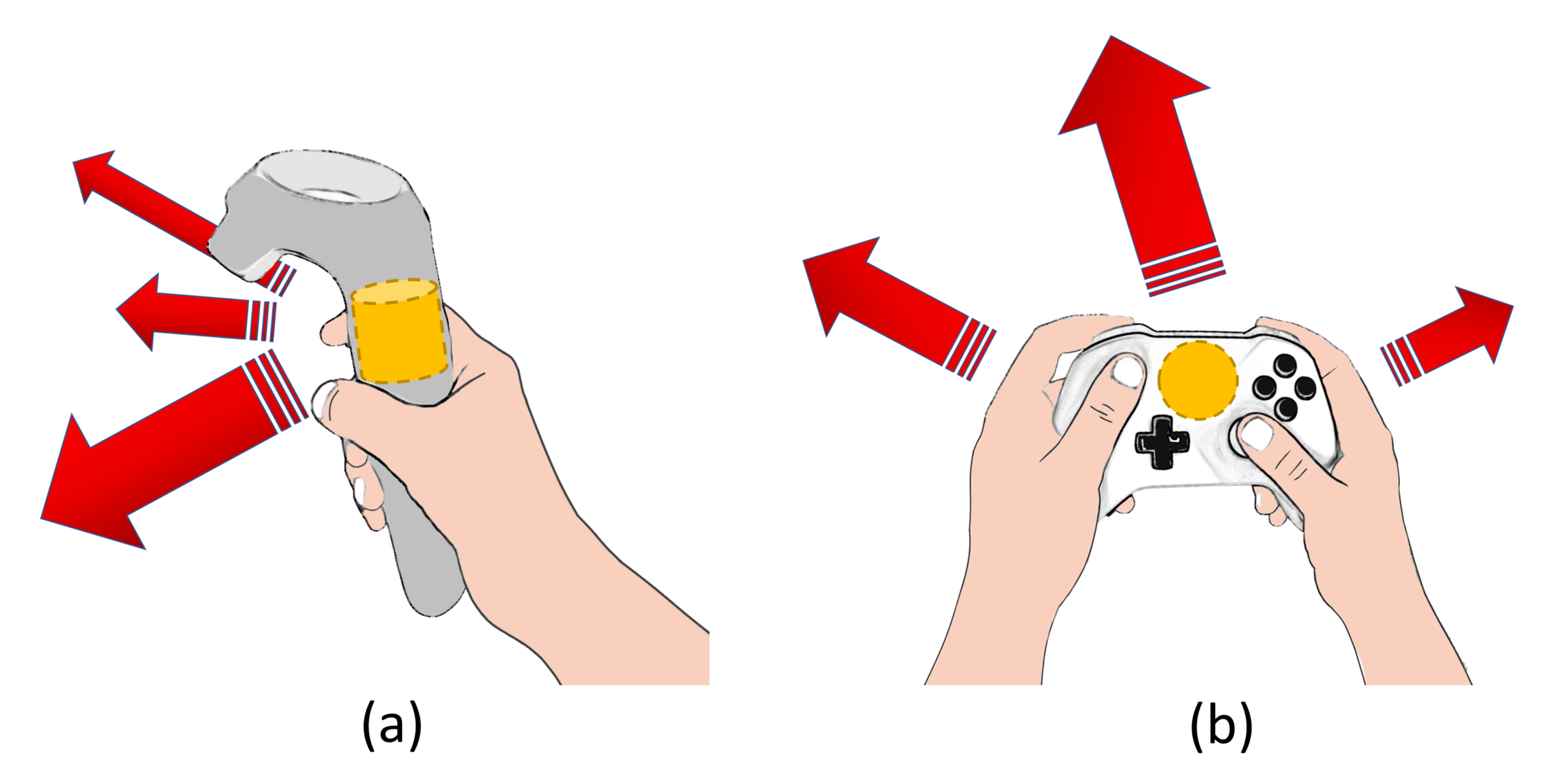
:1. Introduction
2. Materials and Methods
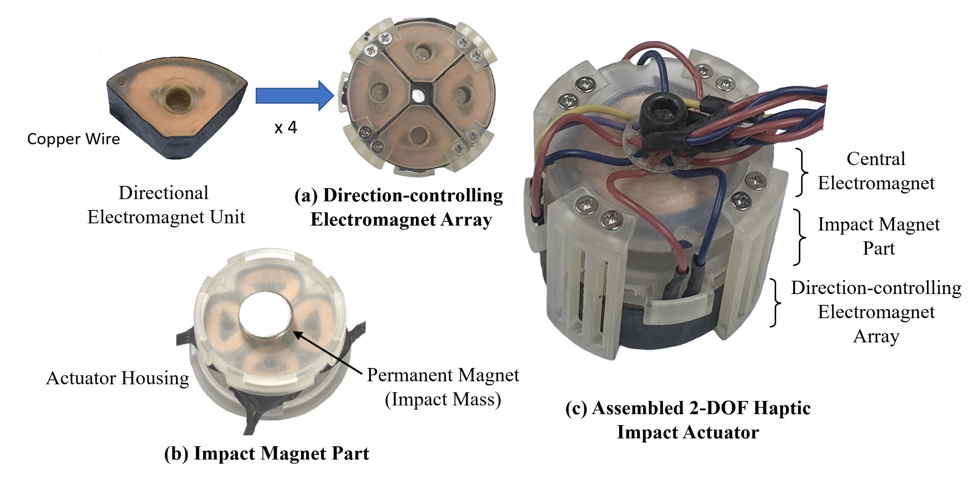
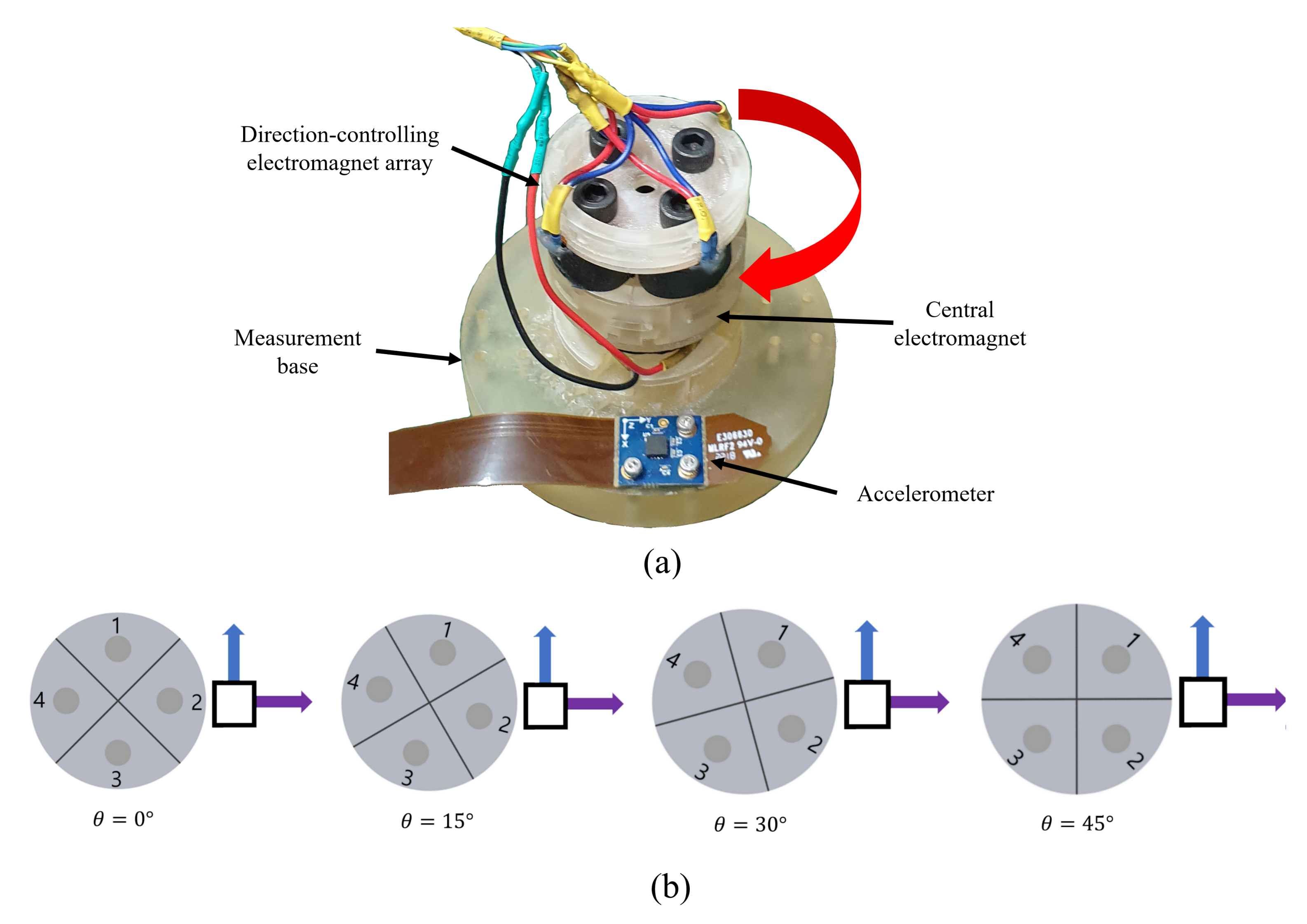
2.1. Design of a 2-DOF Haptic Impact Actuator
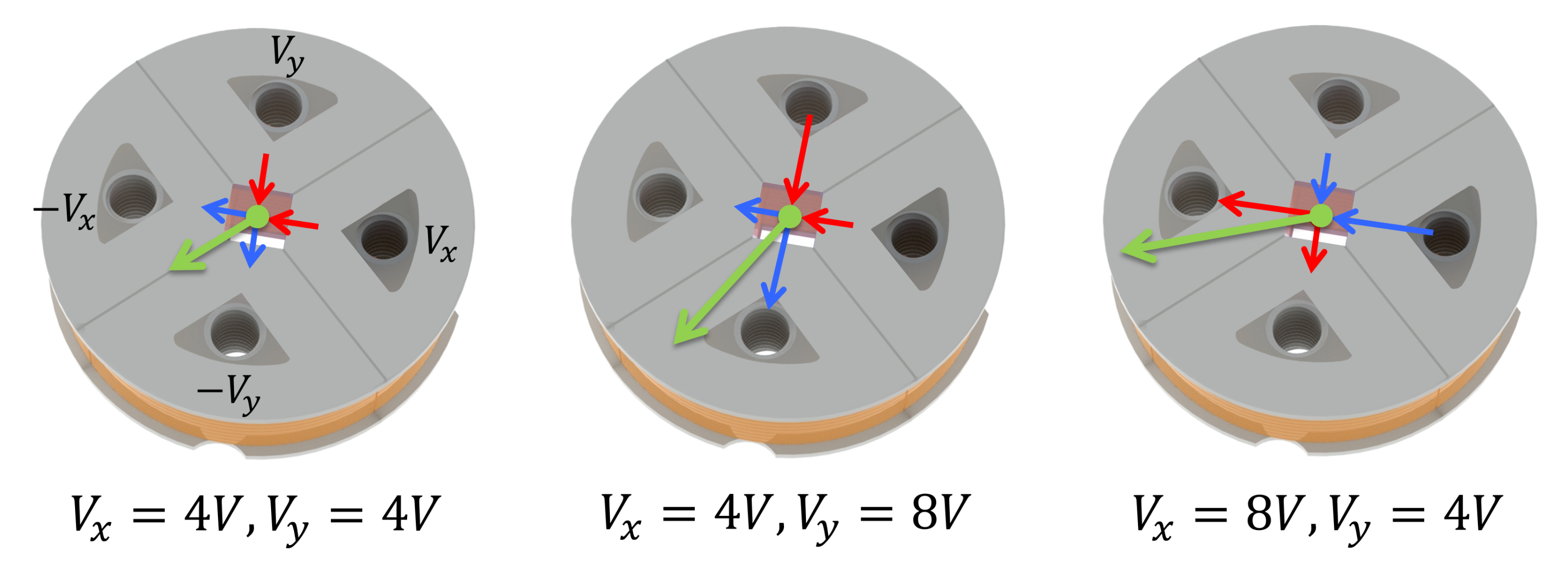
2.2. Control of a Magnetic Field from Multiple Sources for a 2-DOF Impact
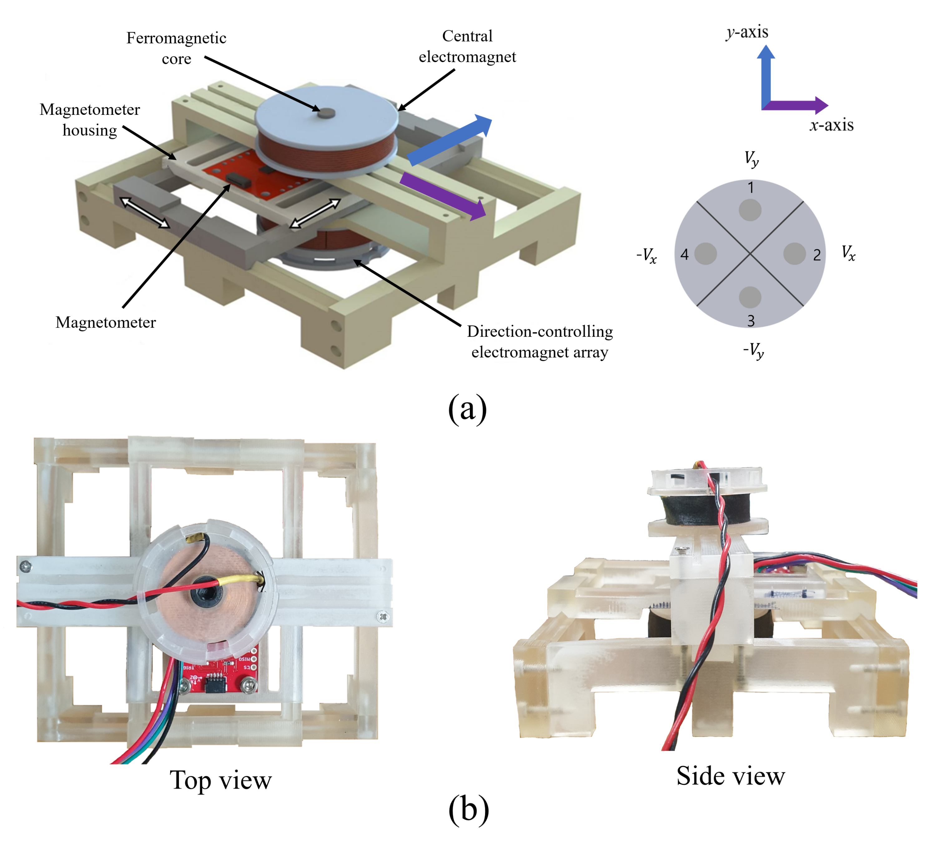
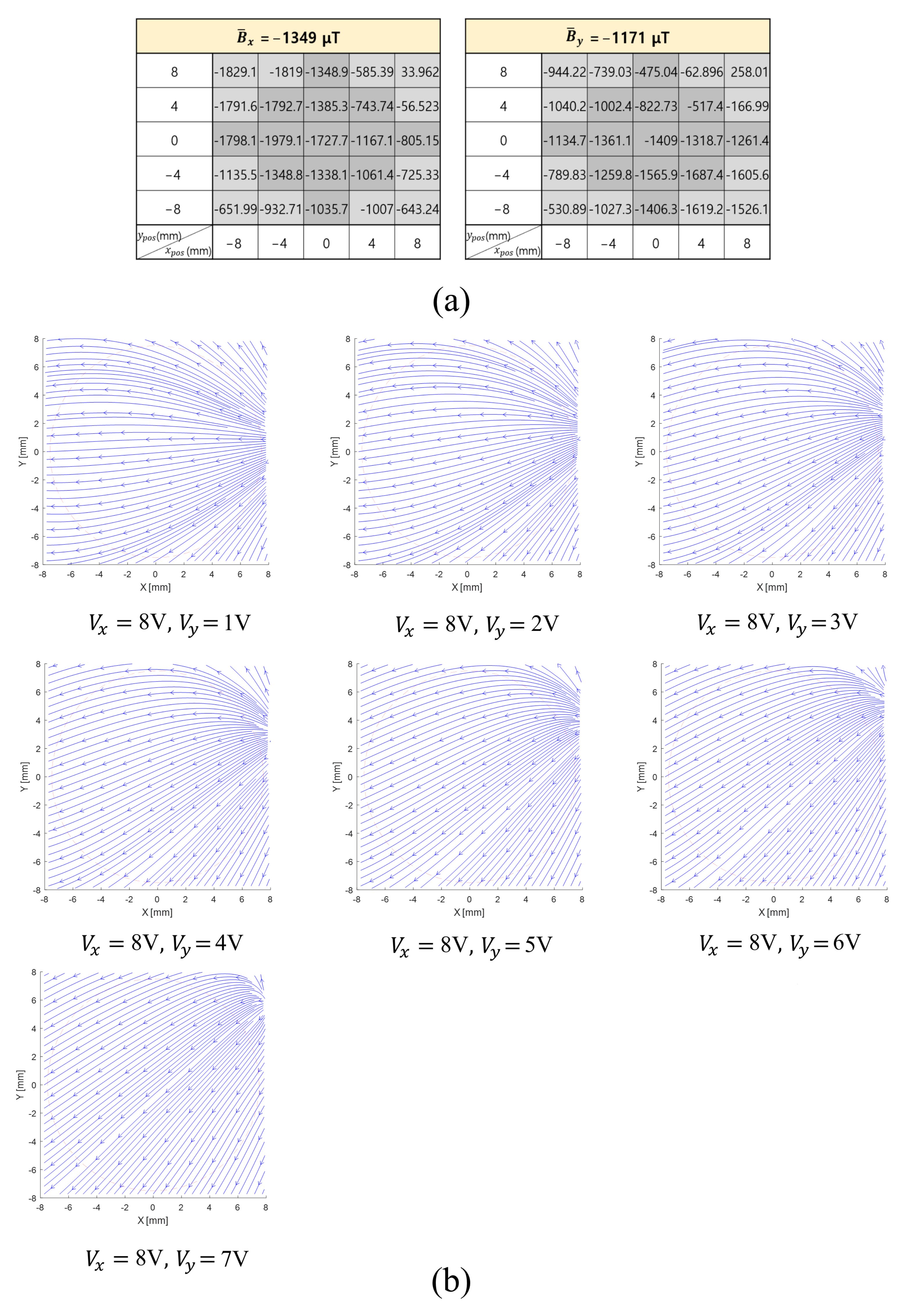
2.3. Distribution of the Magnetic Field inside the 2-DOF Haptic Impact Actuator
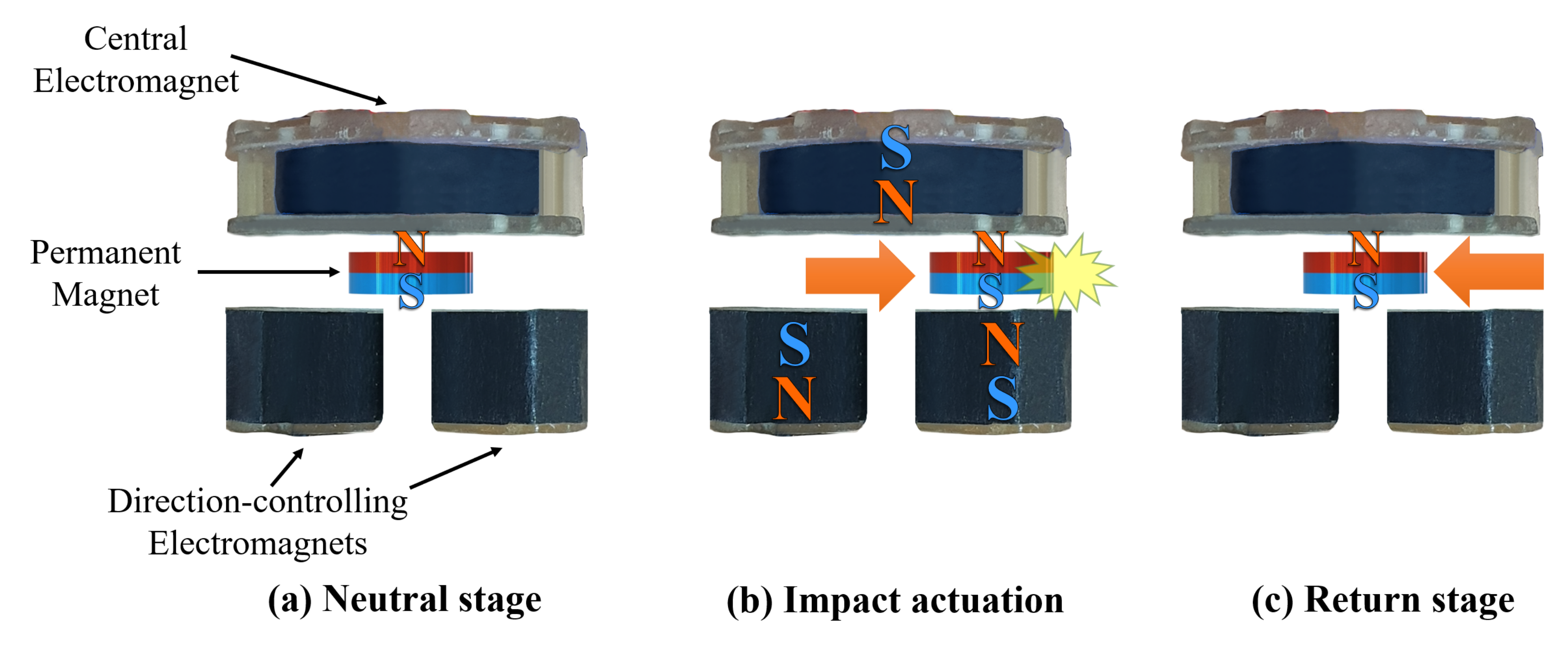
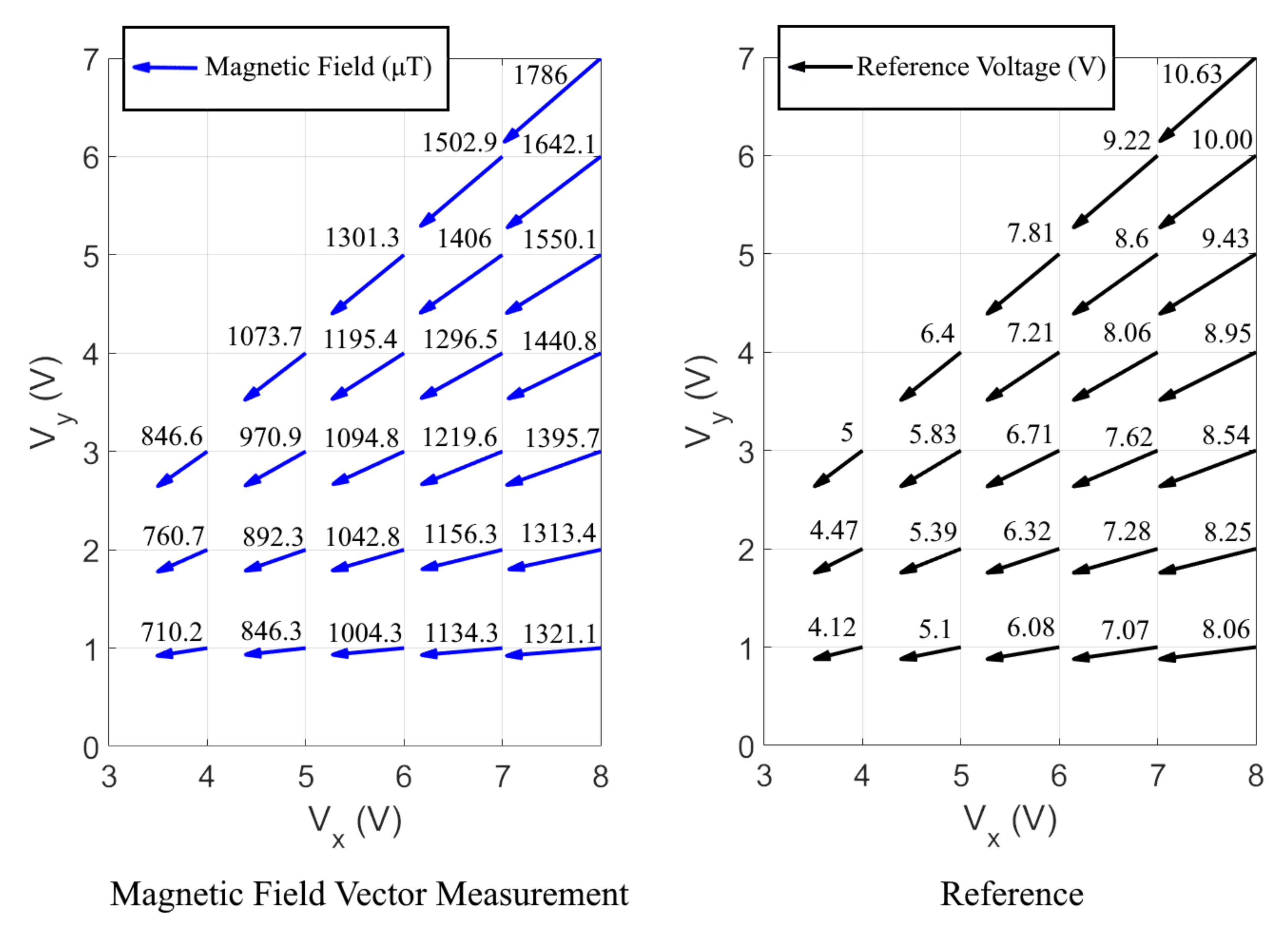
2.4. Haptic Impact by Controlling the Voltage Input
3. Results
3.1. Measurement of the Magnetic Field inside the 2-DOF Haptic Impact Actuator
3.2. Measurement of Haptic Impact by Controlling the Voltage Input
4. Discussion
5. Conclusions
6. Patents
Author Contributions
Funding
Institutional Review Board Statement
Informed Consent Statement
Data Availability Statement
Conflicts of Interest
Abbreviations
| DOF | Degree-of-freedom |
| ERM | Eccentric rotating mass |
| LRA | Linear resonant actuator |
| DEA | Dielectric elastomer actuator |
| VR | Virtual reality |
References
- Chen, H.; Park, J.; Dai, S.; Tan, H. Design and evaluation of identifiable key-click signals for mobile devices. IEEE Trans. Haptics 2011, 4, 229–241. [Google Scholar] [CrossRef] [PubMed] [Green Version]
- Kim, S.-Y.; Yang, T.-H. Miniature impact actuator for haptic interaction with mobile devices. Int. J. Control Autom. Syst. 2014, 12, 1283–1288. [Google Scholar] [CrossRef]
- Yang, T.-H.; Pyo, D.; Kim, S.-Y.; Kwon, D.-S. Development and evaluation of an impact vibration actuator using an unstable mass for mobile devices. Int. J. Control Autom. Syst. 2016, 14, 827–834. [Google Scholar] [CrossRef]
- Sekiguchi, Y.; Hirota, K.; Hirose, M. Haptic Interface using Estimation of Box Contents Metaphor. In Proceedings of the ICAT, Tokyo, Japan, 3–5 December 2003; Volume 203, pp. 3–5. [Google Scholar]
- Liu, R.; Yang, F.; Mu, X.; Yue, H.; Zhu, C. Research on the 2-degree-of-freedom electromagnetic actuator in space. Adv. Mech. Eng. 2018, 10, 1687814017750265. [Google Scholar] [CrossRef]
- Kim, S.; Son, B.; Lee, Y.; Choi, H.; Lee, W.; Park, J. A Two-DOF Impact Actuator for Haptic Interaction. In Proceedings of the International AsiaHaptics Conference, Incheon, Korea, 11–14 November 2018; Springer: Singapore, 2018; pp. 173–177. [Google Scholar]
- Schorr, S.B.; Okamura, A.M. Three-dimensional skin deformation as force substitution: Wearable device design and performance during haptic exploration of virtual environments. IEEE Trans. Haptics 2017, 10, 418–430. [Google Scholar] [CrossRef] [PubMed]
- Leonardis, D.; Solazzi, M.; Bortone, I.; Frisoli, A. A 3-RSR haptic wearable device for rendering fingertip contact forces. IEEE Trans. Haptics 2017, 10, 305–316. [Google Scholar] [CrossRef] [PubMed]
- Chinello, F.; Pacchierotti, C.; Malvezzi, M.; Prattichizzo, D. A Three Revolute-Revolute-Spherical wearable fingertip cutaneous device for stiffness rendering. IEEE Trans. Haptics 2018, 11, 39–50. [Google Scholar] [CrossRef] [PubMed]
- Mintchev, S.; Salerno, M.; Cherpillod, A.; Scaduto, S.; Paik, J. A portable three-degrees-of-freedom force feedback origami robot for human–robot interactions. Nat. Mach. 2019, 1, 584–593. [Google Scholar] [CrossRef]
- Yang, T.-H.; Kim, S.-Y.; Kim, C.H.; Kwon, D.S.; Book, W.J. Development of a miniature pin-array tactile module using elastic and electromagnetic force for mobile devices. In Proceedings of the 2009 World Haptics Conference, Salt Lake City, UT, USA, 18–20 March 2009; pp. 13–17. [Google Scholar]
- Kim, S.-Y.; An, H.-G.; Yang, T.-H. A new modular pin-array tactile device. Int. J. Precis. Eng. Manuf. 2015, 16, 1745–1751. [Google Scholar] [CrossRef]
- Ujitoko, Y.; Taniguchi, T.; Sakurai, S.; Hirota, K. Development of Finger-Mounted High-Density Pin-Array Haptic Display. IEEE Access 2020, 8, 145107–145114. [Google Scholar] [CrossRef]
- Sato, K.; Kajimoto, H.; Kawakami, N.; Tachi, S. Electrotactile display for integration with kinesthetic display. In Proceedings of the RO-MAN 2007—The 16th IEEE International Symposium on Robot and Human Interactive Communication, Jeju, Korea, 26–29 August 2007; pp. 3–8. [Google Scholar]
- Kato, M.; Kono, Y.; Hirata, K.; Yoshimoto, T. Development of a haptic device using a 2-DOF linear oscillatory actuator. IEEE Trans. Magn. 2014, 50, 1–4. [Google Scholar] [CrossRef]
- Kim, G.; Hirata, K. Motion control of a two-degree-of-freedom linear resonant actuator without a mechanical spring. Sensors 2020, 20, 1954. [Google Scholar] [CrossRef] [PubMed] [Green Version]
- Koo, I.M.; Jung, K.; Koo, J.C.; Nam, J.-D.; Lee, Y.K.; Choi, H.R. Development of soft-actuator-based wearable tactile display. IEEE T-RO 2008, 24, 549–558. [Google Scholar] [CrossRef]
- Frediani, G.; Mazzei, D.; De Rossi, D.E.; Carpi, F. Wearable wireless tactile display for virtual interactions with soft bodies. Front. Bioeng. Biotechnol. 2014, 2, 31. [Google Scholar] [CrossRef] [PubMed] [Green Version]
- Pyo, D.; Ryu, S.; Kyung, K.-U.; Yun, S.; Kwon, D.-S. High-pressure endurable flexible tactile actuator based on microstructured dielectric elastomer. Appl. Phys. Lett. 2018, 112, 061902. [Google Scholar] [CrossRef] [Green Version]
- Ji, X. Low Voltage Fast Dielectric Elastomer Actuators. Ph.D. Thesis, The École Polytechnique FéDéRale de Lausanne (EPFL), Lausanne, Switzerland, 20 September 2019. [Google Scholar]
- Zhao, H.; Hussain, A.M.; Israr, A.; Vogt, D.M.; Duduta, M.; Clarke, D.R.; Wood, R.J. A wearable soft haptic communicator based on dielectric elastomer actuators. Soft Robot. 2020, 7, 451–461. [Google Scholar] [CrossRef]
- Heo, Y.H.; Choi, D.-S.; Kim, D.E.; Kim, S.-Y. Flexible Vibrotactile Actuator Based on Dielectric Elastomer for Smart Handheld Devices. Appl. Sci. 2021, 11, 12020. [Google Scholar] [CrossRef]
- Moy, G.; Wagner, C.; Fearing, R.S. A compliant tactile display for teletaction. In Proceedings of the 2000 IEEE International Conference on Robotics and Automatio (ICRA), San Francisco, CA, USA, 24–28 April 2000; pp. 3409–3415. [Google Scholar]
- Kim, Y.; Kim, S.; Ha, T.; Oakley, I.; Woo, W.; Ryu, J. Air-jet button effects in AR. In Proceedings of the 2006 International Conference on Artificial Reality and Telexistence (ICAT), Hangzhou, China, 29 November–1 December 2006; pp. 384–391. [Google Scholar]
- Li, M.; Luo, S.; Nanayakkara, T.; Seneviratne, L.D.; Dasgupta, P.; Althoefer, K. Multi-fingered haptic palpation using pneumatic feedback actuators. Sens. Actuator A Phys. 2014, 218, 132–141. [Google Scholar] [CrossRef]
- He, L.; Xu, C.; Xu, D.; Brill, R. PneuHaptic: Delivering haptic cues with a pneumatic armband. In Proceedings of the 2015 ACM International Symposium on Wearable Computers (ISWC), Osaka, Japan, 7–11 September 2015; pp. 47–48. [Google Scholar]
- Stanley, A.A.; Hata, K.; Okamura, A.M. Closed-loop shape control of a haptic jamming deformable surface. In Proceedings of the 2016 IEEE International Conference on Robotics and Automation (ICRA), Stockholm, Sweden, 16–21 May 2016; pp. 2718–2724. [Google Scholar]
- Song, K.; Kim, S.-H.; Jin, S.; Kim, S.; Lee, S.; Kim, J.-S.; Park, J.-M.; Cha, Y. Pneumatic actuator and flexible piezoelectric sensor for soft virtual reality glove system. Sci. Rep. 2019, 9, 8988. [Google Scholar] [CrossRef] [Green Version]
- Yoshida, K.T.; Nunez, C.M.; Williams, S.R.; Okamura, A.M.; Luo, M. 3-DoF Wearable, Pneumatic Haptic Device to Deliver Normal, Shear, Vibration, and Torsion Feedback. In Proceedings of the 2019 IEEE World Haptics Conference (WHC), Tokyo, Japan, 9–12 July 2019; pp. 97–102. [Google Scholar]
- Sarkar, D.; D’Abbraccio, J.; Camboni, D.; Massari, L.; Arora, A.; Oddo, C.M. A Pneumatic Haptic Display for Collaborative Robotics Applications. In Proceedings of the 2020 IEEE International Workshop on Metrology for Industry 4.0 & IoT, Roma, Italy, 3–5 June 2020; pp. 369–373. [Google Scholar]
- Lee, E.-H.; Kim, S.-H.; Yun, K.-S. Three-axis pneumatic haptic display for the mechanical and thermal stimulation of a human finger pad. Actuators 2021, 10, 60. [Google Scholar] [CrossRef]
- Babic, S.I.; Akyel, C. Magnetic force calculation between thin coaxial circular coils in air. IEEE Trans. Magn. 2008, 44, 445–452. [Google Scholar] [CrossRef]
- Ravaud, R.; Lemarquand, G.; Babic, S.; Lemarquand, V.; Akyel, C. Cylindrical magnets and coils: Fields, forces, and inductances. IEEE Trans. Magn. 2010, 46, 3585–3590. [Google Scholar] [CrossRef]
- Avvari, P.V.; Tang, L.; Yang, Y.; Soh, C.K. Enhancement of piezoelectric energy harvesting with multi-stable nonlinear vibrations. In Proceedings of the Active and Passive Smart Structures and Integrated Systems 2013, San Diego, CA, USA, 10 April 2013; p. 86882H. [Google Scholar]
- Schomburg, W.K.; Reinertz, O.; Sackmann, J.; Schmitz, K. Equations for the approximate calculation of forces between cuboid magnets. J. Magn. 2020, 506, 1–9. [Google Scholar] [CrossRef]
- Cheng, D.K. Field and Wave Electromagnetics, 2nd ed.; Addison Wesley: Boston, MA, USA, 1989; pp. 282–294. [Google Scholar]
- Kutz, J.N. Data-Driven Modeling & Scientific Computation: Methods for Complex Systems & Big Data, 1st ed.; Oxford University Press: Oxford, UK, 2013; pp. 279–286. [Google Scholar]
- Chen, K.-Y.; Patel, S.N.; Keller, S. Finexus: Tracking precise motions of multiple fingertips using magnetic sensing. In Proceedings of the 2016 CHI Conference on Human Factors in Computing Systems, San Jose, CA, USA, 7–12 May 2016; pp. 1504–1514. [Google Scholar]
- Chang, S.; Lin, Y.; Zheng, Y.R.; Fu, X. Simultaneous Detection of Multiple Magnetic Dipole Sources. IEEE Trans. Magn. 2020, 56, 1–11. [Google Scholar] [CrossRef]
- Griffiths, D.J. Introduction to Electrodynamics, 4th ed.; Cambridge University Press: Cambridge, UK, 2017; pp. 266–288. [Google Scholar]
- Park, C.; Park, J.; Oh, S.; Choi, S. Realistic Haptic Rendering of Collision Effects Using Multimodal Vibrotactile and Impact Feedback. In Proceedings of the 2019 IEEE World Haptics Conference (WHC), Tokyo, Japan, 9–12 July 2019; pp. 449–454. [Google Scholar]
- Wang, Y.; Kuchenbecker, K.J. HALO: Haptic alerts for low-hanging obstacles in white cane navigation. In Proceedings of the 2012 IEEE Haptics Symposium (HAPTICS), Vancouver, BC, Canada, 4–7 March 2012; pp. 527–532. [Google Scholar]


Publisher’s Note: MDPI stays neutral with regard to jurisdictional claims in published maps and institutional affiliations. |
© 2022 by the authors. Licensee MDPI, Basel, Switzerland. This article is an open access article distributed under the terms and conditions of the Creative Commons Attribution (CC BY) license (https://creativecommons.org/licenses/by/4.0/).
Share and Cite
Kim, S.; Lee, W.; Park, J. A 2-DOF Impact Actuator for Haptic Application. Actuators 2022, 11, 70. https://doi.org/10.3390/act11030070
Kim S, Lee W, Park J. A 2-DOF Impact Actuator for Haptic Application. Actuators. 2022; 11(3):70. https://doi.org/10.3390/act11030070
Chicago/Turabian StyleKim, Sangyoon, Woochan Lee, and Jaeyoung Park. 2022. "A 2-DOF Impact Actuator for Haptic Application" Actuators 11, no. 3: 70. https://doi.org/10.3390/act11030070
APA StyleKim, S., Lee, W., & Park, J. (2022). A 2-DOF Impact Actuator for Haptic Application. Actuators, 11(3), 70. https://doi.org/10.3390/act11030070