1. Introduction
One trend of Industry 4.0 is advanced robotics [
1]: it predicts a wide use of collaborative robots, the so-called cobots, whose spread is presently growing strongly [
2]. At the basis of the development of cobots, there is the concept that human operators have incomparable problem-solving skills but are restricted in force and precision; on the contrary, robotic systems perform tasks at higher speed, higher repeatability and better productivity but are restricted in flexibility [
3]. This new paradigm avoids the replacement of humans by robots, encourages the human–robot collaboration (HRC) that foresees humans and robots working safely together and sharing the same workspace, and expands the use of cobots also in non-industrial applications.
Although several approaches were defined to ensure the safety of humans, according to the specifications and guidelines defined in [
4], they can carry some risk if human factors are not properly considered. For this reason, on the one hand, the human operator must acquire and improve new skills for safety [
5]; on the other hand, the human operator can have a new role in the interaction with robots whose control can occur without mechanical interfaces (i.e., button switches, touch pads, contact sensors) activated by the operator, but by systems that directly detect the human intention. It follows that HRC can release human operators from heavy and alienating tasks, ensuring their own safety, if effective communication channels between humans and robots are established.
For this reason, the HRC has raised research interests aimed at the robot command by human operators.
The first category of research activities examined in this topic adopts the gesture recognition of the hand or body through several approaches: in [
6], by inertial and magnetic sensors, a data glove captures the motion of the arm and hand, processes the sensors data and runs a robotic arm–hand; with more cameras, the image processing is carried out for gesture and posture recognition [
7,
8,
9]; through a Kinect device [
10], body motion is detected, and a physical image of it is created [
11,
12]. In [
13], image processing was utilized to recognize changes in the mouth shape in order to control a wheelchair-based robotic arm. The Leap Motion controller, a vision-based contactless device, was adopted in several applications to track position, velocity and orientation of one hand of a surgeon and to detect the motion of each finger in order to control a surgical robot arm [
14]; more Leap Motion controllers were adopted for hand tracking in robotic tabletop object manipulation [
15].
For a very easy, intuitive and natural command of robots, a large area of research interests is occupied by the use of biological signals, since they are strictly connected to the human intention in performing a task. A second class of research activities adopts electroencephalograph (EEG) signals, the expression of electrical activity in the brain: in [
16], EEG signals were used to control the e-Puck robot to carry the food of a rat; in [
17], to control a wheelchair to move through a building whose five floors are connected by an elevator. Other examples of use of biological signals are in different kinds of rehabilitation and medical assistive devices (prostheses and orthoses), humanoid robots and industrial robots [
18,
19,
20,
21,
22,
23]. Electromyographic (EMG) signals, an expression of electrical activity of muscles, were widely adopted in several applications: to control the line tracking of a mobile robot [
24]; to control an exoskeleton, powered by pneumatic muscles, that supports the back while performing weightlifting movements [
25]; in combination with an inertial measurement unit (IMU) sensor, to control a mobile robot based on gesture recognition [
26]; in combination with electro-oculography (EOG), EEG, vision systems and head movements, to control a robotic arm [
27] or in combination with a Kinect device [
28].
All the above-mentioned solutions require functional, time-consuming and expensive control systems. Moreover, some sensors can suffer in the external environment: inertial sensors are sensitive to vibrations; vision systems are sensitive to light, which can cause a crash; in some hand poses, vision sensors can show inadequate accuracy. Finally, biological signals are highly sensitive to sensor attachments whose accidental displacements can result in erroneous signals. Since they are typically adopted in the form of analog signals for proportional control strategies, performing signal conditioning techniques is required. In several repetitions of the same human motion, the signals are not the same, and in order to detect human intention, more sensors are required.
To control a laboratory collaborative robot powered by McKibben pneumatic muscles, the aim of this research is to define a hand gesture EMG signal classifier. In pick-and-place tasks, in industrial or biomedical assistive applications, the control unit of the robot requires digital consent signals for reaching defined programed target positions in the space. The conceptual idea of the present research is to generate consent signals from EMG signals produced by finger movements of a human operator. The amplitude or time duration of the EMG signal or the muscular effort of the user are not important, but rather the shape to give to the signal on the basis of the performed movement of the fingers, correlated to the desired robot motion.
The novelty of the presented research is the design of a modeling-based EMG signal (MBES) classifier. With one EMG sensor, properly positioned on the forearm of a human operator, the developed EMG signal classifier recognizes three different finger movements and assigns to each of them a shape defined by a mathematical function model, for a total number of three mathematical function models. For experimentally testing the feasibility of such methodology, each shape is assigned an air pressure level to send to the McKibben pneumatic muscle, which reaches three different length values. In this way, the signal classifier can be used to detect human intention and generate consent signals for robot motion in many robotic safety applications.
The paper is organized as follows: in
Section 2, the application context of a collaborative robot powered by McKibben pneumatic muscles and the rationale for this research are presented; moreover, it briefly introduces the EMG signal; finally, it describes the achieved movements, the instrumentation adopted, how the MBES classifier works, experimental tests to optimize the MBES classifier and the characterization of it;
Section 4 reports the application of the proposed methodology to a Festo fluidic muscle of the McKibben type. The Conclusions Section closes the manuscript.
2. Materials and Methods
2.1. The Application Context
Due to their inherent compliance and safety features, pneumatic artificial muscles (PAMs) [
29] are promising actuators for robotics and automation. They are made of a closed reinforced elastic membrane; air inflation provides for a radial expansion accompanied by an axial membrane contraction, generating a pulling force. One end of the muscle is fixed; the other one moves and applies the contractile force. PAMs can be adopted for rehabilitation robots [
30] and in industrial applications [
31]. For achieving the motion of a joint, PAMs are usually mounted to work in three possible actuation configurations: agonistic–antagonistic, parallel and bio-inspired [
30]. Regardless of the type of configuration, the motion of a joint depends on the pressure level inside the muscles. In the most adopted agonistic–antagonistic configuration, which foresees a pair of muscles whose free ends are connected by a cable around a pulley, the pressure levels provide for muscle changes in length, force application and rotation of the joint.
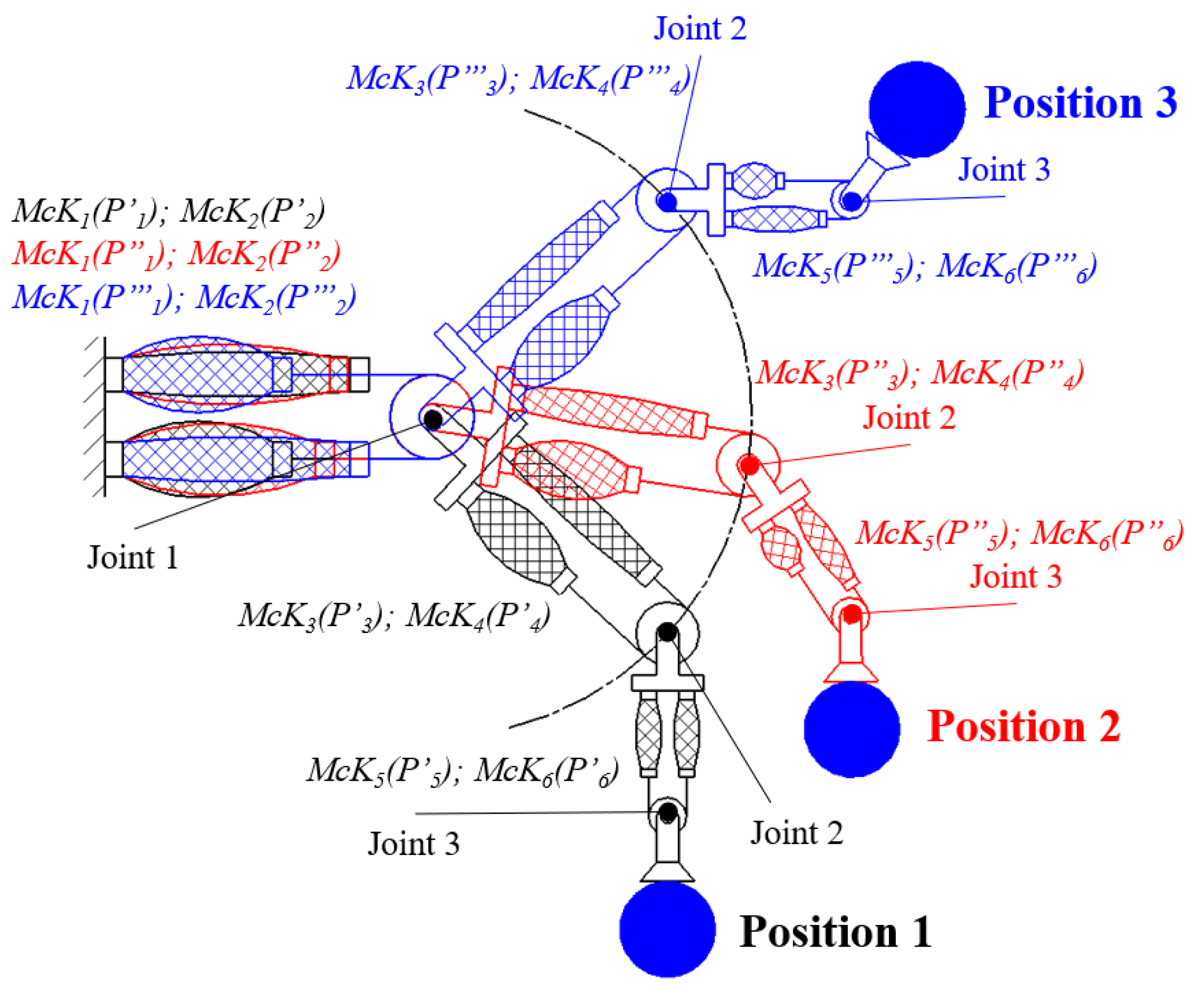
A scheme of a three-degree-freedom robot arm, powered by McKibben pneumatic muscles (McKs) [
32], mounted in agonistic–antagonistic configuration, is shown in
Figure 1. Each joint requires a pair of McKs, for an overall number of six muscles (McK1 and McK2 for the first joint; McK3 and McK4 for the second joint; McK5 and McK6 for the third joint). In order to move the blue-colored ball to three target positions, the muscle pair of each joint requires three different pressure sets (as for the
i-th muscle,
,
and
for the first, second and third position, respectively).
With reference to
Figure 1, in pick-and-place tasks, given the mass of the object to be moved, the target positions and the desired motion speed, it is necessary to know the proper pressure levels to send to each muscle and how to send it. Regarding the first topic, after system characterization, it is possible to map the pressures/positions corresponding to the function of the object to be moved. Regarding the second topic, several control strategies were successfully applied: traditional PI and PID controllers, hybrid adaptive neural network compliant force/position controller, combined PID controller with position feedback, fuzzy neural network controller [
30].
Nevertheless, the main topic is how to generate consent signals to activate the controlled trajectory path of the robot from one position to another, according to the intention of the human operator, especially when a biological signal coming from a gesture is the most suitable to be used, and the above-mentioned sensors cannot be adopted (in noisy, vibrating, light-sensitive environments).
The conceptual idea of the proposed methodology is to associate a proper gesture of the operator to activate a robot for reaching a target position. Hence, it is important to first recognize the gesture; then, a convenient output consent signal must be generated for the robot control unit that allows the robot to reach the desired target position.
The hand finger movements and the referred EMG signals were identified to be suitable for the proposed application.
2.2. EMG Signal: A Brief Description
EMG signals measure the electrochemical activity involved in the activation of the motor units of muscles. Since more motor units are involved in muscle contraction, EMG signal appears as an irregular, noisy, signal that requires a conditioning in terms of filtering, rectification, amplification and smoothing. The amplitudes of the resulting signals increase, not linearly, as a function of the increased muscle effort; nevertheless, for a given effort, EMG signal maintains a certain value for a short period and hence goes down [
33]. EMG signals are normally adopted to diagnose muscle diseases without the need for surgical intervention. In recent decades, they have also been adopted in controlling rehabilitation devices, medical assistive devices and robotic devices because EMG signals provide a measure of the command intention of a user; the electrical activity of muscles occurs prior to muscle contraction [
34], and any change in muscle function is directly reflected in the shape of the generated signal [
35]. For this reason, EMG signals are adopted as analog signals for generating proportional control output signals [
36]. Such signals are usually acquired in the muscle tissue, by means of needles, or on the surface of the skin over the location of a muscle, by surface electrodes [
34]. The latter are the only convenient devices for HRC, since needles must be surgically implanted but render it difficult to precisely recognize the amplitude, the effort and the time duration of muscular activity of a person due to many reasons:
the acquired signal is the resulting signal generated by the activity of different muscles involved in the same movement;
individual muscles are associated with performing not only one single movement but also many kinds of movements;
the level of activity of each muscle of a person varies slightly for the same movement. Obtaining the same EMG signal amplitudes for the same movement is difficult even with the same person, since EMG signal is a biologically generated signal;
the role of each muscle in a specific movement of a joint varies according to the angles of the joint. The amplitude and time duration of the signal depend on the effort level of the muscle and its duration.
In order to overcome these problems, an MBES classifier of EMG signals has been conceived and developed.
The following Section describes how the developed MBES classifier works from the definition of the movements to their recognition under different operative conditions.
2.3. The Hand Finger Movements
The choice of proper hand gestures is based on two considerations. The MBES classifier must adopt only one EMG sensor, for the simplicity of the installation of sensor probe and to reduce computational time for signal processing. The movements must be ergonomically simple to perform and easy to remember for human operators.
Then, after several trials in performing gestures of the hand, three easy finger movements have been achieved so that they have different more recognizable signal shapes: the flexion of the index finger, the one-by-one ordered flexion of all fingers starting from the little one and the contemporary flexion of all fingers.
Figure 2a–c illustrate the performance of the three movements. The muscles mainly involved in such movements are the flexor digitorum profundus and the flexor digitorum superficialis, placed in the forearm, as shown in
Figure 2d.
2.4. Instrumentation
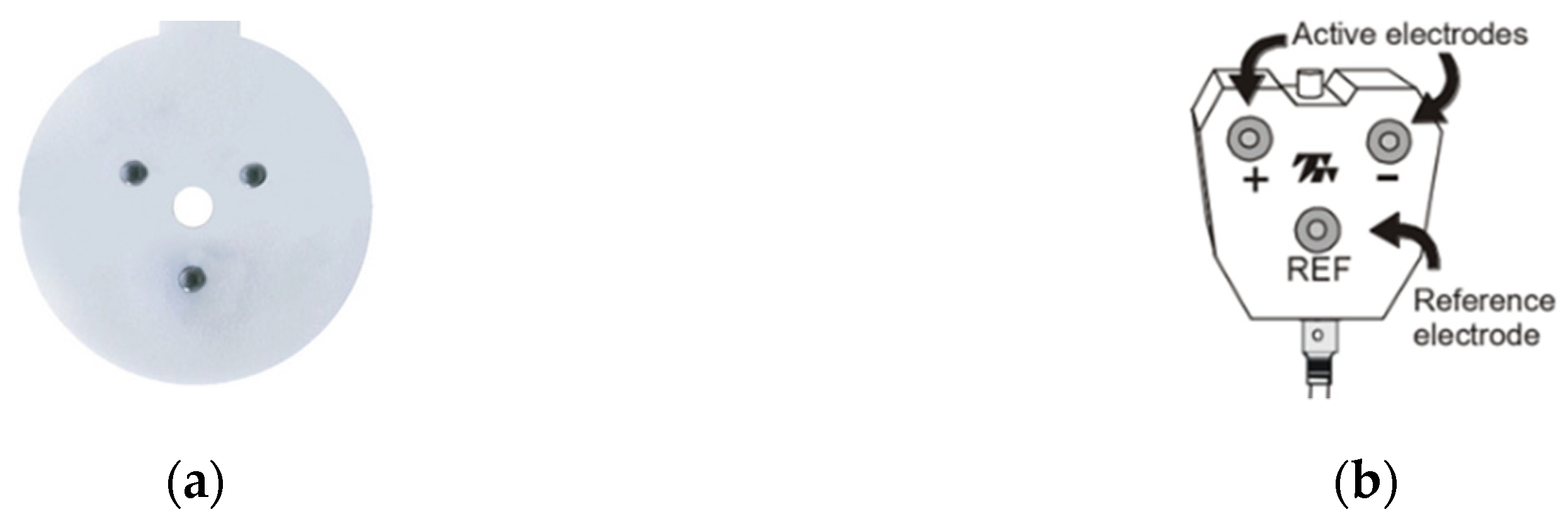
To detect muscle activity, during a muscle tension, only one EMG sensor is used. It is possible for a subject to use whatever hand is preferred, regardless of whether the person is left handed or right handed. The probe of the sensor (
Figure 3a) is connected to the electrode board (
Figure 3b) containing three electrodes: two active ones (+, −) and a reference one (REF). The probe must be placed on the forearm, as shown in
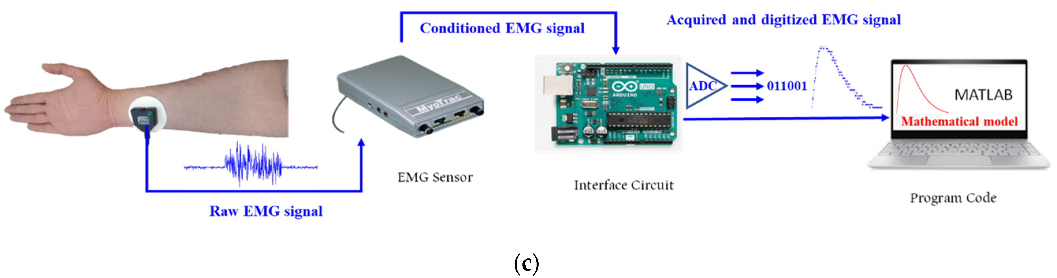
Figure 3c, with active electrodes parallel to the muscle fibers. A wire joins the electrodes board with MyoTrac™ EMG sensor (Thought Technology, Montreal, QC, Canada). It incorporates sensitive electronic circuitry that eliminates noise from raw muscle signals, thus rectifying, amplifying and smoothing them. Due to high sensitivity, MyoTrac™ does not require skin preparation to place the sensor probe.
For the purposes of present research, via controls on the sensor front panel, the gain of the sensor has been set to X100 position (signal range 0.08–2000 μV), and the frequency range for the signal detection has been set to WIDE (20–500 Hz). The conditioned output of the EMG sensor is in the form of an analog signal. Such signal is extracted by the 0–2 V analog port placed on one side of MyoTrac™.
The MBES classifier is based on the application of a mathematical function model to the shape of the acquired EMG signal. For the implementation of the mathematical modeling method, a laptop PC (Intel i5, 10th generation; USB3 ports), with MathWorks Matlab running (release R2021b), has been adopted. Since the PC is not equipped with an analog input port, an Arduino UNO (A1) board has been used as an interface circuit for this purpose. The communication between the PC and A1 occurs by an USB port. A Matlab code manages the analog-to-digital converter (ADC) of A1 to read the digitalized signal to be processed for the mathematical modeling method in Matlab. Although the maximum frequency sampling of A1 is equal to 9615 Hz, the current sampling frequency of the overall data acquisition system managed by Matlab drops to about 75 Hz. Then, each 13 ms a sample is acquired. Such value depends on two reasons: time delay due to the communication between A1 and the USB port; time delay due to the Matlab code that sends a read request for a signal sample to A1, and after it has been obtained and stored, repeats the same request for the next signal sample and so on.
2.5. The MBES Classifier
There are many ways that can be used to classify EMG signals, such as Neural Networks [
37], Fuzzy Logic [
38], Support Vector Machine [
39] and other computational techniques [
18,
40]. All of these methods calculate some features (mean value, RMS value, etc.) from portions of EMG signals; on the contrary, the proposed method uses the entire EMG signal because the time duration of it is brief enough, therefore, no criticism can occur due to the brief time delay between the hand gesture and the robot motion and extracting some portions of the signal could cause neglect of some information that is included in it.
The proposed method is based on modeling the muscle signal, resulting from a particular movement, by a proper mathematical model. This makes it easier to recognize the movements of a person based on the signals produced by muscles. After several preliminary tests carried out with some volunteers, three mathematical models for each of the movements mentioned in
Section 2.3 have been found to describe the best fitting curves of the signals referred to those movements. For the sake of simplicity, high speed of calculation and no requirement for pre-training, such as Neural Network, among the several techniques to find a mathematical model for a time-varying signal, the curve fitting using the non-Linear Least Squares Estimation method (NLSE) has been adopted. This method finds a mathematical formula for the best non-linear function (exponential, statistical or fractional function) passes from all the values of the samples of the acquired EMG signal. In order to determine the best mathematical formula for each movement, the trial-and-error method has been used to choose the mathematical model that best fits the curve of the EMG signal for each movement.
The EMG signal curve of the first movement is modeled by an Exponential function, given by Equation (1):
The second movement is modeled by a Gaussian function, given by Equation (2):
The third movement is modeled by a Fractional function, given by Equation (3):
Figure 4 shows the data set of the EMG signal of each movement and the fitting curves with the corresponding mathematical models and equations. With reference to the sampling frequency, for each second, about 75 samples of the conditioned EMG signal are acquired.
To assess the accuracy of the modeling process, for each fitting curve, the R-Square standard, the root mean squared error (RMSE) and the sum of squared error (SSE) criteria were applied [
41,
42], calculated as shown in
Table 1.
The modeling evaluation criteria values in
Table 1 show the convergence between the real EMG signal curve and the curve of the referred mathematical model function. R-Square is close to 1, and RMSE and SSE are close to 0, which means the modeling process can be considered successful.
On the basis of such results, the MBES classifier works as follows. The running Matlab code continuously acquires all the samples coming from the EMG sensor; when the amplitude of the
i-th sample is equal or exceeds the threshold value 0.0099 V, Matlab code starts to store and create a data set made of the next samples until their amplitude exceeds the threshold value. If the size of the data set is lower than 10, the data set is deleted, and Matlab code waits until a new data set exceeds the threshold value; if the size of the data set is higher than 10, the data set is modeled using all three specified mathematical models. To calculate the unknown coefficients of the considered mathematical equations, firstly, random values are assumed for the coefficients, and then, the trust region algorithm [
43] is used to adjust their values; it is the most advanced function in Matlab, which is faster than other algorithms at finding the unknown coefficients. In order to determine whether this signal is caused by any of the three specified movements, or whether it is an unwanted signal, the R-Square criterion is examined for the three models. If the R-Square value of the signal is less than 90%, then the signal is considered undesirable; if the R-Square value is greater than 90%, then the model with the highest R-square value determines the movement.
A preliminary campaign of tests has been carried out to validate the proposed methodology. Each movement has been repeated 15 times by a volunteer and processed according to the described process.
Figure 5 shows the real and model-based EMG signals of the three movements with different amplitudes.
The curves show that, first of all, the three movements have been recognized. This means that this method is not affected by the change in amplitude and time duration of the signal, but it only depends on the shape of it. It means that a human operator could perform the same movements under different conditions (slow, fast, concentrated or not, etc.), but the signal shapes do not change.
2.6. Characterization of the MBES Classifier in Different Operative Conditions
In order to achieve the best position of the sensor probe on the forearm and to take into account the exerted effort for performing the three movements, two different sets of experimental tests have been carried out. The same test protocol was followed in a laboratory environment by 7 randomly selected subjects (2 females and 5 males) at various ages (average age 38 ± 28) so that they have different effort levels, and their EMG signals have different amplitudes.
2.6.1. The Test Protocol
This has been provided to all subjects to advise them on how to perform the tests. After the first description of tests, the following steps must be followed by each volunteer subject:
- 1.
the subject has to carry out preliminary first attempt trials to be familiar with the tests;
- 2.
regarding the mounting of the sensor on the forearm, the following indications have to be considered:
- 2.1.
before mounting the sensor, the placement of the sensor probe along the forearm (the Capture area showed in
Figure 6) has to be preliminarily marked with a pen;
- 2.2.
the probe of the EMG sensor has to be placed as shown in
Figure 3c, with active electrodes parallel to muscle fibers;
- 2.3.
the probe has to be placed so that the center of it, between the three electrodes, corresponds with the mark made according to point 2.1;
- 3.
after mounting the EMG sensor, the subject has to run the Matlab program and start signal acquisition;
- 4.
the subject has to perform the described movements;
- 5.
it is better to take a rest of 50 s after completing 10 trials.
2.6.2. The Sensor Probe: Evaluation of the Best Positioning
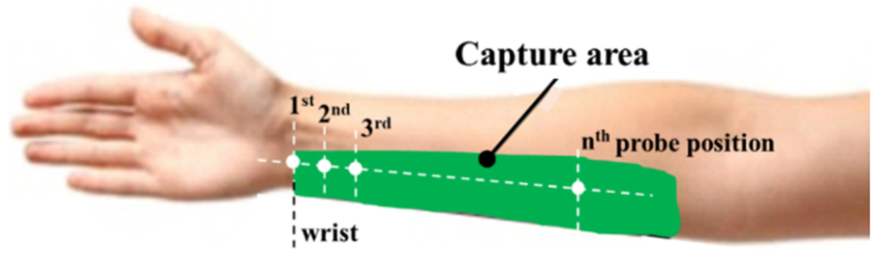
The effective area for the placement of the EMG sensor probe is the green-colored one shown in
Figure 6. From the left, the origin of this area is the wrist, where the first probe position is defined as first position. Other positions (white points in
Figure 6) were achieved by a right shift of the probe by 10 mm, maintaining the active electrodes parallel to the muscle fibers.
In order to achieve the best positioning of the sensor probe, in each position, all subjects have carried out 30 attempts for each of the three movements. EMG signals have been acquired, processed and classified. In preliminary analyses of EMG signals, over 110 mm away from the wrist, EMG signals have not matched the same shapes shown in
Figure 4. The range 0–110 mm has been selected for the achievement of the best position. Then, in relation to the sensor probe position and for successful trials of movement recognition, the average number of successful trials, the average R-square standard value and the average amplitude of the signal were computed.
Results are plotted in
Figure 7. They show that the best locations to place the EMG sensor are within the range 40–90 mm from the wrist. It means that the operator can change the position of the probe in that range, which makes the recognition methodology of EMG signals flexible.
2.6.3. Evaluation of the MBES Classifier during Movement Effort Change
The exerted effort during the performance of any movement differs in the same person because it depends on the physical condition of the person (whether they are active, tired or frustrated). The purpose of this experimental test set has been to evaluate the performance of the MBES classifier in recognizing the same specified movements under different effort conditions.
In addition to the instrumentation described in
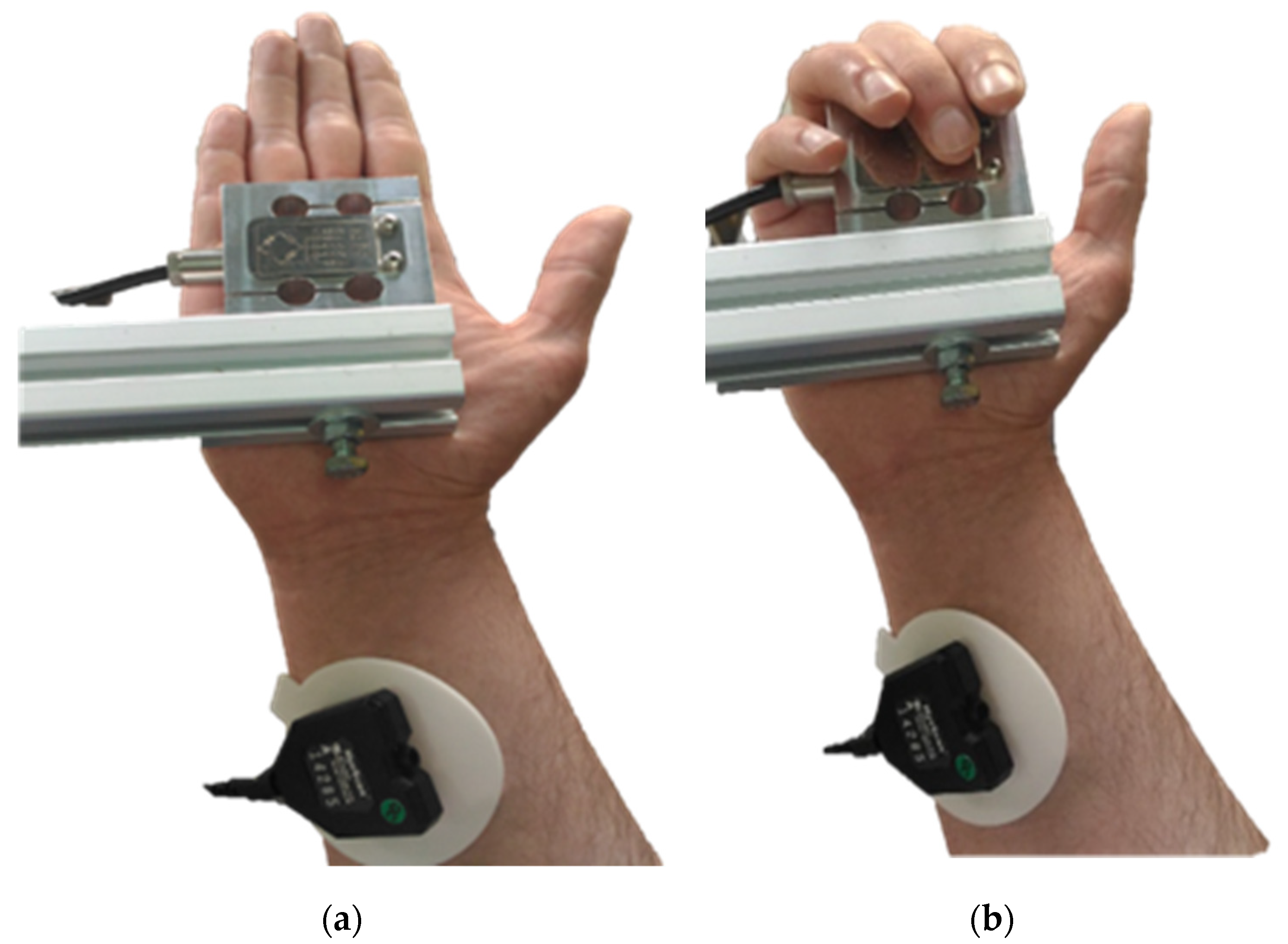
Section 2.4, a load cell (AEP Transducers, TS10, full scale 10 kg, sensitivity 2 mV/V) was adopted to measure the effort during the execution of the movement. A voltmeter was adopted by subjects to monitor the load cell output, as a reading of the current effort level.
The three movements were applied to the load cell placed between the fingers and an aluminum profile, as shown in
Figure 8.
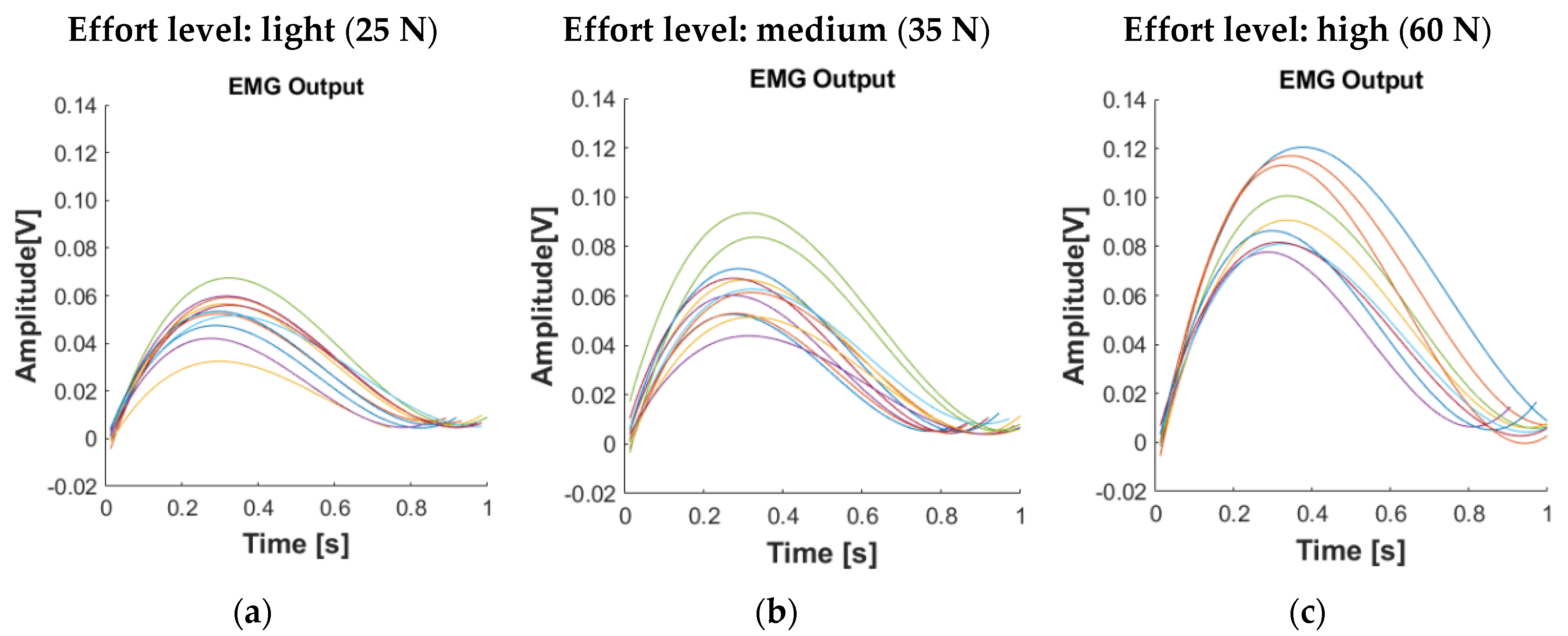
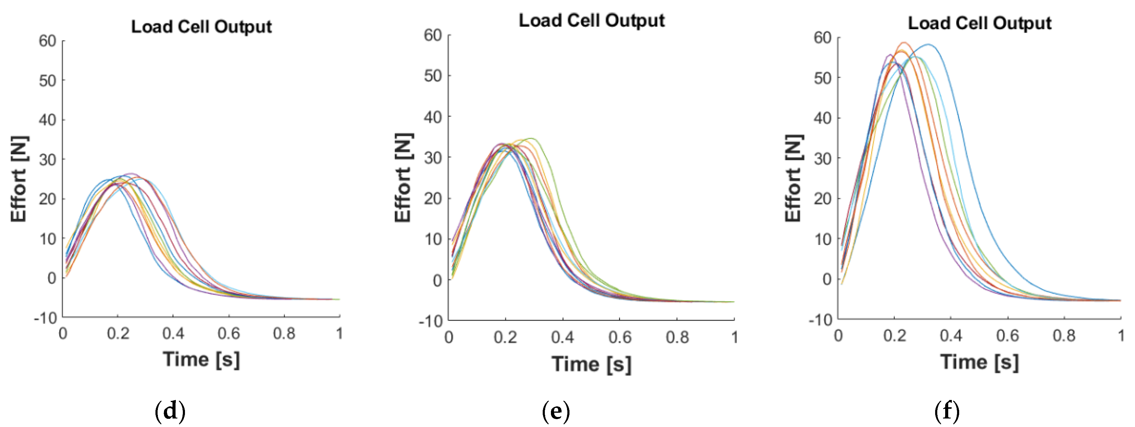
Three qualitative effort levels were determined for each movement: light, medium and high, according to the light (about 25 N), medium (about 35 N) and high (about 60 N) finger effort levels of the subjects on the load cell. Given a subject, for each effort level and each movement, EMG signals were collected in the same graph as for the referred load cell output signals. With reference to the third movement,
Figure 9 shows the model-based EMG signals and the corresponding load cell output signals.
Figure 9 shows that at a specific effort value, EMG signals change their amplitudes and time durations, depending on the difference in the physical condition of the subject, but the shapes of them do not change. Moreover, the average signal amplitude increases with increasing effort, as typical of EMG signal. Similar results have been achieved as for the first and second movements. Therefore, the MBES classifier can be considered capable of recognizing the movements for specific levels of effort despite the changes in the physical conditions, revealed by different amplitudes of the EMG signals.
Table 2 shows the overall results of the set of subjects as a percentage of the success rate in recognizing each movement.
Unlike the first movement, the second and third ones reveal some failures. In particular, the success rate percentage was equal to 100% for the first movement, 99.14% for the second movement and 99.42% for the third movement. These results are in accordance with the expectations. They probably occurred because the second and third movements were quite similar, even if the fingers are flexed at different time intervals. Nevertheless, from the foregoing results, it is concluded that the MBES classifier can be applied to people in general.
3. Experimental Application: Control of McKibben Muscle
The aim of the experimental activity has been to apply the proposed MBES classifier to a real robotic system. For such purpose and with reference to
Figure 1, only one muscle has been considered. The focus is to control muscle length by controlling the inner air pressure value on the basis of the recognition of EMG signals generated by the three finger movements. In the case of the robotic system shown in
Figure 1, a set of lengths of the muscles pairs will be assigned to each finger movement.
A fluidic muscle Festo MAS-20-300 (external diameter 20 mm; length at rest 300 mm), whose working principle is the same as that of McKibben pneumatic muscle type, has been adopted.
Firstly, the displacement pressure curve of the muscle has been achieved in experimental tests carried out by a proper testbed. It comprises a portal frame in aluminum profiles equipped with the muscle whose free end is fixed to a wire linear position transducer (Celesco DV301-0020-111-1110, f.s. 508 mm), a multimeter, for reading the output voltage signal of the position transducer, a precision pressure regulator (SMC IR2010) and a Bourdon type manometer (f.s. 4 bar). The fixed end of the muscle is screwed to the portal frame.
An isotonic test, with null load, has been carried out. The shortening of the muscle has been measured as a function of the inner pressure inside it. Starting from length at rest, pressure has been increased by 0.10 bar, from 0.0 up to 4.0 bar. For each pressure step, the shortening has been measured. The experimental characteristic curve and the fitting one are reported in
Figure 10.
Then, three muscle shortening (MS) levels have been chosen for the application: 10 mm, 30 mm and 50 mm. Solving the equation reported in
Figure 10, the corresponding pressure values (P) have been computed equal to 1.14, 2.14, and 3.55 bar, respectively.
Finally, the Matlab code (attached in the form of
Supplementary Materials) has been improved in order to manage an analog output port of Arduino UNO, in order to create the command tension for a pneumatic proportional pressure control electro-valve. A Metalwork Regtronic ¼ valve (range 0–5 bar; command tension 0–5 Vdc) has been identified for generating the required pressure values. Hence, according to the three recognized movements, 1, 2 and 3, the three values of the voltage signal, 1.14, 2.14 and 3.55 V, respectively, have been sent to the valve, as shown in
Figure 11. Voltage signals have been sent as step signals.
Two volunteers carried out 10 tests for each finger movement, for an overall amount of 60 tests. The sensor probe has been applied at about 60 mm from the wrist. The average time durations of the first, second and third movements have been approximately 0.5 ± 0.095 s, 1.42 ± 0.076 s and 1.72 ± 0.003 s, respectively. The time to classify the signal and generate the analog output signal is not dependent on the movement time duration and measures about 0.7 ± 0.07 s. In some trials, movements have not been properly recognized. For the same volunteer, in one case, the second movement was recognized as the third one, and in one case, the third movement was recognized as the second one. These errors have occurred in correspondence with the last repetitions of the second and third movements, probably due to an imperfect execution of the trial.
Results (a movie is attached in the form of
Supplementary Materials) demonstrate the feasibility and effectiveness of the developed classifier. Delay times between gesture and command occurrence are consistent with delay times of any mechanical command switch. It means that no excessive delay should be introduced by this command technique in biomedical, industrial and non-industrial applications.
4. Conclusions
In this paper, an effective and adaptable modeling-based EMG signal classifier has been proposed, as first application, for pick-and-place tasks of collaborative robots. The MBES classifier can be used as an intuitive control unit in industrial, non-industrial and biomedical robotic applications. The proposed classifier depends on representing the EMG signals with mathematical models. These mathematical models have been selected so that they are the best fitting with the EMG signals curves. Only one EMG sensor was used to recognize three different movements of the hand fingers, and many experiments were conducted to find out the best area on the forearm where the probe of the sensor should be placed. The MBES classifier is independent of the amplitude of the EMG signal and the required exerted effort to perform the movements because it relies on the shape of EMG signals, and many tests using load cell were conducted in order to verify it. Finally, experimental results on a set of subjects have shown the effectiveness of the modeling-based EMG signal classifier. The results showed a good agreement between theoretical expectations and practical results. In real robotic applications, the classifier has demonstrated the ability to recognize finger movements and create the proper command signal of a McKibben-type pneumatic muscle. The adoption of only one EMG sensor has demonstrated the simplification of the installation of the sensor probe and a low computational time for signal processing. Nevertheless, it could be a limit of the proposed approach because it is possible to detect signals generated in the same capture area, only one, and for this reason, only a small number of movements can be recognized. More movements could be detected, probably with a success rate percentage equal to 100%, if more sensors were adopted. Moreover, another limit is represented by the current set-up that requires wiring, a personal computer and a microcontroller. Instead of Arduino Uno, a more powerful microcontroller, programed to find the best fitting curves, could be adopted. The best scenario will be the adoption of embedded wireless sensors able to recognize more movements faster and transmit consent command signals to the control unit of a robot. As expected, a short training period was required for volunteers to perform the proper movements. Moreover, movement performing does not require concentration or particular psychophysical involvement. These aspects have been highly appreciated and accepted by volunteers, and the model seems to be promising for widespread application in several other fields, such as, for example, domotics, for the control of home devices; gaming, above all for the virtual reality; augmented reality, for choosing options or for browsing documents, information, instruction pages.


