Abstract
The current state of the art in compliant actuation has already good performance, but this is still insufficient to provide a decent autonomy for the next generation of robots. In this paper, a next step is taken to improve the efficiency of actuators by tackling and enhancing the Series-Parallel Elastic Constant Torque Actuation (SPECTA) concept, which has previously been analyzed in simulations. In this work, the efficiency is increased further by decoupling the springs and their driving parts through the use of locking mechanisms, such that the motors are not always loaded and the springs can easily store energy from both input or output. Simulations have been performed to confirm this and they also showed that, in the SPECTA concept, it is always better to use high-speed motors instead of high-torque motors, even with non-efficient gearing. In this paper, the SPECTA concept is also validated experimentally with the use of a newly built test setup. In light of the obtained results, showing an increase in efficiency for almost all working points, it can be stated that SPECTA is a promising new actuation technology that allows for an increase in energy recuperation, efficiency, and autonomy.
1. Introduction
In recent years, robots and robotic devices have taken a more prominent stage in society and industry, since they have become less dependent on external power sources. To facilitate the integration of robots into our daily lives, some major problems still need to be tackled. One of those problems is their autonomy, which is still not sufficient. For specific examples, one can look at the robots of Boston Dynamics. The Atlas robot has 60 min autonomy with a battery of 3.7 kWh to move a body of 80 kg [1,2], whereas Spot can move without load for approximately 90 min with a battery of 605 Wh [3]. Stretch, on the other hand, which was released in early 2021, has 16 h autonomy. This is due to the large space available in its base although its total weight is 1200 kg [4]. Looking at these numbers, it can be concluded that the autonomy still needs to be improved, unless when sacrificing weight and size, which in turn leads to other downsides such as, e.g., loss in payload, reduction of safety, a decrease of sustainability, etc. [5].
This poor autonomy is due to several factors: unoptimized power sources, the power electronics that use a large chunk of the available energy, the actuators which still induce a lot of losses, etc. For this last category, namely the actuation technology, already a lot of innovation has become possible throughout the years by introducing compliance into the actuation. Compliant elements are energy buffers which provide an additional power path that can be used to lower the losses of the actuator. A good example is motor regeneration: an electric motor can convert back mechanical power into electrical power but the power will first go through the transmission before going through the motor, which will cause losses.
If the energy is instead stored in a compliant element, placed between the load and the motor, the losses can be virtually canceled.
The energy can then be provided by the compliant element to the load and this without losses once more. Different compliant actuators have been developed for that purpose:
- Series Elastic Actuators (SEA) [6,7,8,9,10,11,12]: actuators with a compliant element placed in series with the motor which modifies the speed profile of the motor and hence reduces mainly the friction- and gearing losses.
- Variable Stiffness Actuators (VSA) [13,14,15,16,17,18,19,20,21,22,23,24,25]: SEAs where the joint stiffness can actively be changed to allow a reduction of the losses. This broadens the range of applicability of the actuator, although these actuators use a second motor that also consumes power, increasing the weight, volume, and complexity of the actuator.
- Parallel Elastic Actuators (PEA) [8,26,27,28,29,30]: actuators with a compliant element placed in parallel with the motor which modifies the torque profile of the motor and hence reduces mainly the Joule and gearing losses.
- Clutched PEAs (cPEA) [30]: PEAs where the parallel spring can be (de-)coupled from the output in case the power path offered by the spring is not beneficial at a given moment. This also comes at the cost of a clutch which consumes power and increases the weight, volume, and complexity of the actuator.
- Series-Parallel Elastic Actuators (SPEA) [31,32,33,34,35,36,37,38]: these actuators combine both series and parallel compliant elements to alter both the speed and torque profile of the motors and hence have the benefits of both the SEA and PEA. SPEAs also have the added benefit of redundancy, which allows the load to be divided among multiple motors. This is especially useful to reduce the Joule losses since they scale quadratically with the load torque. In light of the above arguments, SPEA displays the most benefits for improving autonomy, but this at the cost of increased complexity, weight, and volume.
It was, however, shown in [39] that there is still room for improvement for the SPEA. In this work, which led to the development of the initial Series-Parallel Elastic Constant Torque Actuation or SPECTA, the main goal was to design an actuator that can solve the ’torque loss’ issues of the SPEA by introducing an adapted topology that is no longer susceptible to this issue. Since the torque loss originates from the deflection-dependent nature of the springs that are used in the SPEA, it was proposed to replace these springs with a constant torque mechanism. This would allow it to keep its torque when the motor angle is altered. As a consequence, this also enabled the spring to be used as a storage element, since the (dis)charge of the spring would not have any influence on the produced torque. For this constant torque mechanism, it was decided to use so-called ’constant torque springs’, since they provide a decent amount of torque in a compact design that also has a stable behavior. Implementing these in the +SPEA concept resulted in an actuator topology, as shown in Figure 1.
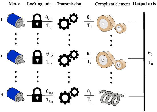
Figure 1.
Graphical view of the initial SPECTA concept [39].
In this topology, all branches contain constant torque springs, which are the so-called discrete torque units. Since continuous torque is necessary, the last unit uses a linear spring. The topology shown in Figure 1, however, still contains some non-ideal parts, although a large increase in efficiency was simulated compared to an equivalent SPEA [39]. One of the main downsides is that a direct path between the motors and the output is present, leading to power consumption even when the load is driven from the output side. This can also lead to inefficient back-driving behavior. The problem stems from the initial design of the +SPEA, as can be seen in Figure 2b. It has already been partially solved by the intermittent design of the iSPEA (depicted in Figure 2a), where only one motor is in contact with the load, and by using holding brakes in the +SPEA, the motors are prevented from being loaded. For the iSPEA, this occurs, however, at the cost of speed, since it has to go through a cycle. For the +SPEA, it is at the cost of brakes that also consume energy. A perfect solution would thus consist of the motor decoupling behavior of the iSPEA and the multiple recruitment possibility of the +SPEA, while avoiding the use of brakes when the motor is in stasis.
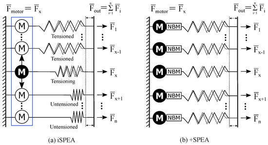
Figure 2.
Overview of the SPEA architecture, which can be divided into iSPEA and +SPEA. (a) iSPEA schematic, consisting of parallel branches with springs that can be variably recruited by one motor that moves using a dephased intermittent mechanism, represented by the blue rectangle. (b) +SPEA schematic, which consists of parallel branches, each with a motor that can variably recruit the spring present in their unit. Additionally, a Non-Backdrivable Mechanism (NBM) is added to lock the motor such that the spring can be tensioned without drawing power from the motor. Adapted from [31].
In this work, the direct-path problem of the SPECTA (i.e., the motor is always loaded) will be solved by placing locking mechanisms at the input and output of the constant torque spring. The spring can thus be both (dis-)charged by the motor and the output, without them interfering, and hence avoiding back-driving motors. It should, however, be noted that one of the cases involves both clutches being open (i.e., the spring is completely decoupled from external influence). In this case, all energy stored in the spring would be lost. As such, the final SPECTA topology will also contain a locking mechanism to store the spring energy. Based on the analysis conducted in [40], electromagnetic clutches were selected for the coupling between the motor and the spring as for the spring and the output branch, respectively, ensuring a reliable and easily controllable locking behavior. To store the energy in the spring, when both clutches are open, it was opted to attempt a more passive solution, namely, a ratchet and pawl mechanism.
This paper is structured as follows: First, in Section 2, the dynamic model of the actuator is described. Next, our method is presented in Section 3. This comprises a task description, the selection of the specific actuation units and topology, as well as the description of the optimization strategy and the metrics used to compare the chosen SPECTA actuator with a comparable stiff actuator. Based on these previous two sections, simulations and result discussions are given in Section 4. The theoretical gains of the SPECTA actuator in terms of energy efficiency are also discussed. To validate the simulations, a test setup is built, which is shown with all details in Section 5. With the setup being built, experimental validation is performed and presented in Section 6. At the end of the paper, the discussion in Section 7 considers the simulations and experiments, together with conclusions that can be drawn from all the results regarding the SPECTA.
2. Construction of the Dynamic SPECTA Model
To begin the development of the novel SPECTA, the ideas mentioned in the introduction will be added to the topology of Figure 1. This imposes that locking mechanisms, i.e., the electromagnetic clutches and ratchet and pawl mechanism, are added in all constant torque units/branches of the SPECTA model. It is also chosen that the last branch is still stiff and not compliant such that the output can be tracked more easily.
2.1. Model
The topology of this novel SPECTA is shown in Figure 3, together with all used variables.
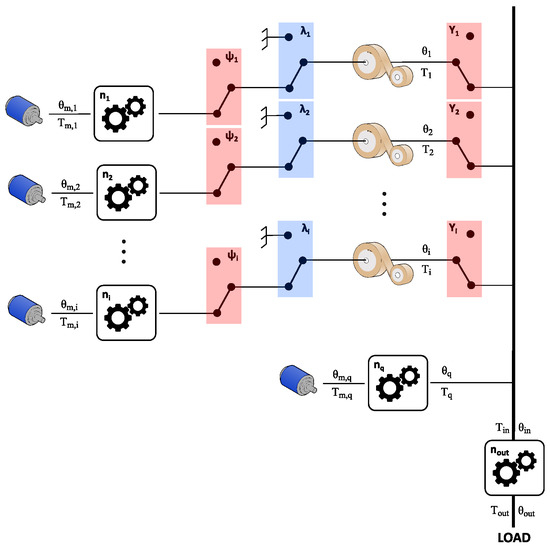
Figure 3.
Overview of the SPECTA actuator for case 2. The blocks with and represent respectively the electromagnetic clutch at the input, the ratchet and pawl system to lock the spring, and the electromagnetic clutch at the output. The electromagnetic clutches are represented by the red boxes, whereas the ratchet and pawl mechanisms—by the blue boxes for clarity.
In this figure, the blue boxes with the variable represent a ratchet and pawl locking mechanism. The lockings have only two possible states, namely, locked and unlocked, and can be described by
The red boxes with the or variable represent a clutch mechanism. The clutches have only two possible states, namely, on and off, and can be described by
The physical states of these boxes are clarified in Figure 4.
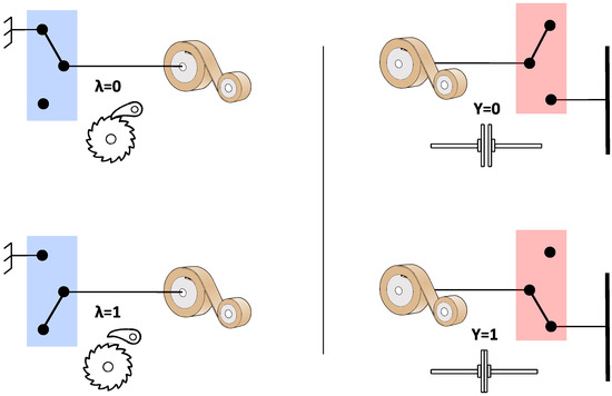
Figure 4.
Visualization of the different states of the used locking mechanisms. The blue boxes always represent a ratchet and pawl mechanism and the red boxes always represent an electromagnetic clutch. Here, the visualization of the variable is not shown explicitly, but it is the same as for .
Now, only the explanation of all symbols required to describe the SPECTA is still needed to complete the dynamic model. These are described in Table 1.

Table 1.
Nomenclature of the SPECTA concept.
2.2. Graphical Simplification
Before we proceed with the analytical description of the SPECTA, it is also useful to provide a less abstract depiction of the workings of the SPECTA. This simplification is shown in Figure 5. In this configuration, the spring of the first constant torque unit (top branch) is charged by the motor, whereas the spring of the second constant torque unit (lowest branch) is in direct contact with the load. In this example, the constant torque units are coupled to the output axis by a belt (gray band) and, for both units, the ratchet and pawl are in their unlocked state. The stiff (continuous torque) unit, which is shown in the middle branch, is coupled directly to the output (load).
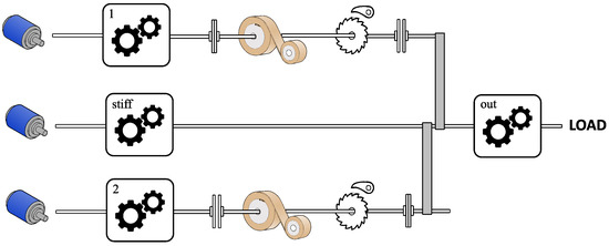
Figure 5.
View of a specific configuration of the SPECTA actuator. In this configuration, the spring of the first constant torque unit (top branch) is charged by the motor, whereas the spring of the second constant torque unit (lowest branch) is in direct contact with the load. In this example, the constant torque units are coupled to the output axis by a belt (gray band) and for both units, the ratchet and pawl are in their unlocked state. The stiff (continuous torque) unit, which is shown in the middle branch, is coupled directly to the output (load).
2.3. Equations
2.3.1. Discrete Part
The dynamics of the motor in the discrete part can be described by
The behavior that is shown in Table 2 is desired:

Table 2.
Overview of how the speed of the constant torque spring is defined for case 2 with respect to the clutch, ratchet, and pawl variables. The value 0 represents the upper state of all colored boxes (in Figure 3), whereas the value 1 represents the lower state of the colored boxes. This explanation is also shown in Figure 4.
This imposes that the kinematic relations for the discrete part is given by:
Note: One can see that from the output side, nothing changes in the equation in comparison with case 1. Only an extra part is added that describes the charging of the motor.
Table 2 also indicates that the following boundary conditions are valid:
- Ensure that the switching variables are always either 0 or 1:
- Ensure that there is no mechanical blockage caused by the ratchet (both on input and output side):
- Avoid charging the spring when it is connected to the output (otherwise, the motor is directly coupled to the output):
- Avoid uncontrolled unloading of the spring (since this might cause breaking of the spring):
Here, it is explicitly stated that the motor can only charge when the output is not connected to the spring.
Again, the clutches have only two possible states, namely, on and off, which can be described by
The ratchet and pawl system, on the other hand, shows the following behavior:
By incorporating the effects of both input and output, the state-space form of the discrete part becomes
For the simulations that will be performed later in this paper, two cases will be considered. In the first one, the springs are assumed to be perfect whereas, in the other one, the springs are considered to be real (hence, the effect of hysteresis is added). In this way, the effect of hysteresis can be analyzed. As such, the torque generated by the springs is calculated by
In all these equations, the efficiency function of the transmissions is needed, which can be described by
Considering all of this, the current and voltage can be rewritten as
This implies that the power can be calculated as follows:
2.3.2. Continuous Part
For the stiff unit, the dynamics are given by
With
The power and state-space calculations are the same as for case 1, and will hence be omitted.
Output Definitions
Finally, the output torque can be defined as follows:
The transmission equation is given by
3. Setup of the Simulations
Now that the dynamic model is described, we can continue by setting up all parts of the simulations, starting by presenting the task that will have to be performed.
3.1. Task Description
The performed simulation (and later the experiments), conducted for both the SPECTA and a comparable stiff actuator, consists of lifting a 1 DOF link (pendulum) that moves from to a certain fixed angle after 15 s. Then, it starts to oscillate with a frequency dependent on the value of for 20 s. Afterwards, the link returns to , such that the complete task takes 50 s. This task is chosen since it is basic enough that engineering intuition can be used as a type of feedback loop to verify whether the used optimization behaves correctly or not. The inertia, damping coefficient, and gravitational torque of the link are, respectively, kgm, Nms/rad, and Nm. Here, different values are used for to evaluate the performance of the actuators for all kinds of situations.
The output torque of the task is given by
To avoid confusion, an overview of all experiments that will be shown in this paper is provided in Table 3.

Table 3.
Overview of the experiments that will be shown in this paper. For the simulations, all details were performed, but only two working points are shown in detail in this paper to avoid repetition. All shown experiments were performed for a gravitational torque () of 15 Nm.
3.2. Selection of Actuators and Equivalent Stiff Motor
To identify clearly which kind of motor is preferred in certain cases, we will choose to use two constant torque units (i.e., two branches with constant torque springs are used), both in the simulations and later for the real tests. From these two units, one is driven by a high-torque motor (unit 1 in the simulations and tests) and one by a high-speed motor (unit 2). In this way, we can derive from the optimal control simulations which one behaves better in which situation. For the choice of a high-speed motor, a Maxon EC-4pole 22, Brushless motor, 120 W, was selected; as a high-torque motor, Maxon EC 60 Flat, Brushless motor, 200 W, was chosen. Their characteristics are presented in Table 4 and Table 5, respectively. For the last continuous branch/unit, it is chosen to also use this Maxon EC-4pole.

Table 4.
Characteristics of the selected high-speed motor (Maxon EC-4pole, Brushless motor, 120 W, part number 311536) and the corresponding gearbox (Maxon GP22HP, part number 370784).

Table 5.
Characteristics of the selected high-torque motor (Maxon EC 60 Flat, Brushless motor, 200 W, part number 614949). Since this is a high-torque motor, no gearing is coupled directly to it.
Comparing compliant redundant actuators with stiff ones successfully is difficult since different criteria can lead to different results, as shown by, among others, Furnémont [41]. In that work, it is posed that the best way of comparison is to have motors with a comparable total rated power since that allows for the most equivalent actuator characteristics. However, since in this work the capacity of the motors is limited due to the inherent nature of the constant torque spring to which they are coupled, a stiff motor with a comparable total torque was selected since in this case this will lead to actuators with comparable characteristics (i.e., if SPECTA can complete the required task, the equivalent stiff actuator should be able to do it as well). In this work, the Maxon RE 50, Brushed motor, 200 W, was selected as stiff comparison. For the real tests, this will thus be chosen to act as a load motor. Its characteristics, together with the ones of its gearbox (Maxon GP 62 A), are listed in Table 6.

Table 6.
Characteristics of the selected load motor (Maxon RE 50, Brushed motor, 200 W, part number 370,354) and its corresponding gearbox (Maxon GP 62 A, part number 110,506).
Note: The comparison is not performed with an actuator that has a similar structure, e.g., the +SPEA, as the results vary a lot depending on the chosen spring stiffness of the +SPEA.
To fill the last part of the topology of the different cases and to deliver enough torque, a gearbox (Neugart PLFE064, ratio 1:10) is placed at the output.
The SPECTA will use two springs of Nm and a continuous torque motor that can produce Nm. The stiff load motor can produce Nm. Considering the gearing of 1:10 between the SPECTA and the load motor, it is clear that they have approximately similar torque, making them equivalent.
3.3. Control Strategy: Optimal Control Theory
To verify the possible energetic improvement of SPECTA, simulations are performed using optimal control [42,43]. It was chosen to use this control strategy since this method has already been shown to work well in finding the best energetic performance for compliant redundant actuators [41]. To apply this control, an optimal control problem () should first be formulated, based on the dynamics, constraints, control variables, and the cost function that should be minimized.
3.3.1. Cost Function
In this simulation, the goal is to minimize the electrical consumption of the used motors. The cost function of the consumed energy is obtained by
3.3.2. Control Variables
To control the system, two types of variables are used, namely, the motor current and the switching states. The control variables are summarized under the vector , which is calculated by
3.3.3. Dynamics
To implement the dynamics of the SPECTA in the , the mathematical descriptions of both the speed and acceleration of each of the branches should be written down in the simulation software. These formulations can be found in Section 2.
3.3.4. Constraints
In order to ensure that the simulations are realistic, some constraints need to be added in the . In short, we can identify the following types of constraints:
- Torque-equality constraintIt needs to be imposed that the sum of the torques of each unit should be equal to the output torque. The constraint is intrinsic to the system for each case and is written as follows:
- Switching constraintThis comprises all the necessary constraints that are needed to make sure everything functions as described in Table 2. In general, the form is as follows:
- Boundary condition constraintThe begin- and end-states should also be imposed (e.g., angle, speed, etc.) In this simulation, these are considered to be zero:
- Inequality constraintThe inequality constraint ensures that the motors do not saturate and overheat, the following inequality constraints are imposed:With:The minimal and maximal values imposed are retrieved from the motor and spring data sheet.
To perform an optimization of all control variables such that the most energy efficient trajectory can be found, the problem is discretized into points. In each of these points, the OCP is solved separately. While solving this, special attention is given to the control variables of the locking mechanisms (, , and ). If the same level of discretization were applied to these control variables, this would result in a rather ‘jerky’ behavior. This is to be avoided since it would, first, not always be physically realizable (due to the mechanical response time) and, second, not benefit the energy consumption. Making use of longer time steps before the control variables can change would ensure that the optimization takes optimal care of the benefits of these mechanisms. This can be achieved by defining a discretization with fewer points for , , and . By imposing that these control variables can only change times (with ) during the entire trajectory, these control variables will stay longer in a certain state, which is exactly the desired behavior. The added benefit is that the optimization itself will take a lot less time to calculate. This is similar to the procedure in [41], except that in [41], the larger time step was only used for the break variable of the motor.
Note: The OCP is solved using AMPL in combination with the nonlinear programming solver Knitro. The simulations in this chapter were performed using a 2.8 GHz Intel Core i7-7700 HQ with Matlab R2021a. For the optimization in AMPL, the Crank Nicholson method was used for the discretization and some of the fixed boundary conditions, e.g., Equations (5)–(8), were softened by turning them into inequality constraints to reduce processing time. This, however, did not change the results. For all simulations described in this chapter, it was chosen to select and , since this provided the best trade-off between computation time and performance.
3.4. Comparison Metric
To discover why SPECTA is either more or less energy efficient, not only the total consumed energy should be compared, but also the specific losses. It has already been shown in [35,41] that the electrical power of a unit can be written such that the individual losses become visible:
From Equation (27), one can see that four different terms contribute to the electrical power: the Joule losses (), the friction losses of the motor (), the gearing losses , and the mechanical power . By integrating these terms over the task time, the energy related to each of them can be found. By doing so, both actuators can be compared in terms of specific losses and the total consumed energy.
4. Simulation Results
Since everything is now described, the simulations can finally be performed and the results can be analyzed. To separate the individual effects, we will, however, divide the simulations into two cases. Namely one in which the springs are assumed to be ideal (case 1) and one case in which the hysteretic behaviour of the springs will be added (case 2).
4.1. Simulation Results: Case 1
For this first case, we can start to compare the SPECTA with the equivalent stiff actuator, since now no charged springs are already available. We are, however, still assuming ideal springs since we are in case 1. For these simulations, the first unit is driven by the high-torque motor without any gearing, whereas the second unit is driven by the high-speed motor with gearing. The results of the simulation of case 1 are shown in Figure 6. Here, the energy consumption for moving a 1 DOF link at a gravitational torque of 15 Nm is plotted for an entire range of and for both the SPECTA and its stiff equivalent.
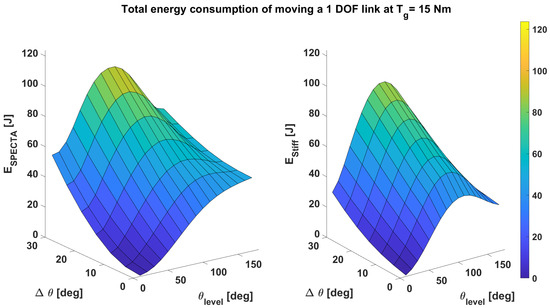
Figure 6.
Comparison of the total energy consumption for moving a 1 DOF link at Nm for an entire range of and . The left part represents the consumption of a SPECTA actuator, whereas the figure to the right represents the consumption of an equivalent stiff actuator. In this simulation, an ideal constant torque spring is assumed. Here, all simulations point out that the most energetic optimal SPECTA is the one where only one spring is recruited, namely, the one that is connected to the high-speed motor.
One particular thing to note is that all simulation points show that the most energetic optimal SPECTA is the one where only one spring is recruited, namely, the one that is connected to the high-speed motor. To explore this further, we will first look at the comparison of the SPECTA with its stiff equivalent. At first glance, it is, however, not so easy to see the exact difference between these two plots. To facilitate the comparison, an overview of the gain in energy consumption is provided in Figure 7. In this surface plot, all regions that have z-values greater than zero represent the regions in which the SPECTA displays a lower energy consumption than its stiff equivalent. The values smaller than zero display logically the opposite behavior.
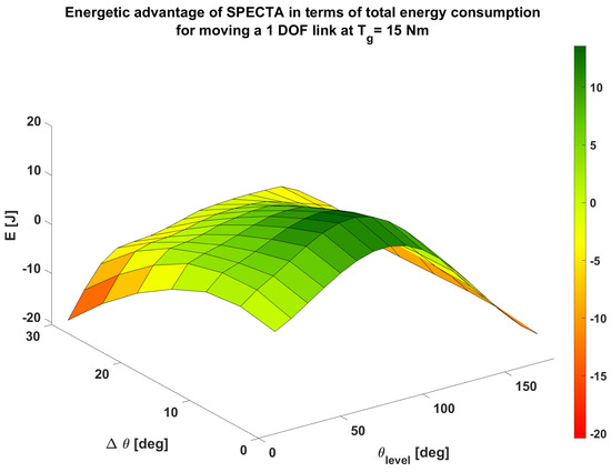
Figure 7.
Overview of the gain in total energy consumption for moving a 1 DOF link at Nm for a SPECTA actuator in comparison to an equivalent stiff actuator. In this simulation, an ideal constant torque spring is assumed. The values of energy consumption that are positive represent the regions where a SPECTA actuator uses less energy than the stiff equivalent for the same task. In the regions where the value is smaller than zero, the stiff actuator uses less energy.
In this plot, one can see that SPECTA is superior in almost all rather static cases (i.e., ) and especially for the values close to , since these tasks are even more static. It could already be assumed that SPECTA behaves especially well for the Joule losses because SPECTA is a redundant actuator. From this, we can conclude that the other losses become more dominant than the Joule losses in the regions in which the SPECTA consumes more energy than its stiff equivalent. Since the simulations show that the most energetic optimal SPECTA is one that only uses the spring that is coupled to the high-speed motor (i.e., motor 2, not the high-torque motor, nor a combination of both), it can be assumed that this is caused by the friction losses which become too dominant. The conclusion can be drawn that the gearing losses are not the main driving force for this behavior, since motor 1 has no gearing and hence no gearing losses. Therefore, its poor performance must result from other losses. An explanation for this can be found when observing the friction losses (). The only difference between the high-torque motor branch and the high-speed motor branch is the friction coefficient (). The high-torque motor has a friction coefficient that is 34 times higher than the one of the high-speed motor, which is most likely the reason behind the dominance of the friction losses.
The comment can be made that it is expected on first glance that the influence of the gearing losses is more dominant than that of the friction losses, since motor 2 has a gearing with a rather poor maximal efficiency (). To observe the behavior of the SPECTA in detail, we will consider two working points. First, one where SPECTA is better than the stiff one () and, second, one where the stiff equivalent actuator consumes less energy for the same task ().
- This working point is one where the SPECTA behaves better than its stiff equivalent. In Figure 8, some details of this working point are shown—(a) the angle, (b) the rotational speed, and (c) the torque are shown for each of the different units, together with (d) the switching variables of the ratchet and pawl mechanism and (e) the switching variables of the electromagnetic clutch.
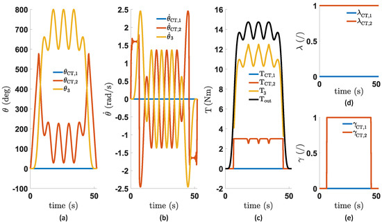 Figure 8. Overview of (a) the angle of each of the units, (b) the rotational speed of the units, (c) the torque of each unit, (d) the states of the ratchet and pawl mechanism of each unit, and (e) the states of the output clutch mechanism of each unit. These simulations were performed for a task angle with a variation of for a SPECTA with an ideal constant torque spring that is not charged yet.In (a), one can see that only the second spring, i.e., the one driven by the high-speed motor, is being charged. This charging by the motor only happens in the first and last of the 8 time frames in which the states of the locking mechanisms can change. The variable which decides when the motor is coupled to the spring is not shown explicitly in Figure 8, since its value is already known when you know the values and , which are respectively shown in (d) and (e), in combination with the constraints shown in Table 2. In (a), we can also see that the spring is charged just enough by the motor to complete its full cycle. The optimal control approach even results inthe constant torque spring working shortly in its rising region instead of its constant torque region, which can be witnessed in (c), since some small interruptions are visible in the constant torque profile that the spring delivers (orange line). These interruptions, which represent the spring being in its rising region, are shown in Figure 9. It should, however, be noted that this region is practically not viable to use since it is unpredictable what the exact torque value will be for a certain angle.
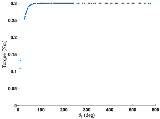 Figure 9. Torque–angle plot of the constant torque spring behavior used in the simulations.When looking at the losses for this task, shown in Figure 10, it starts to become clearer why the friction losses are the most dominant in deciding which spring to use. Here, the values seem small (SPECTA: J and Stiff: J), whereas the gearing losses result in much greater losses (SPECTA: J and Stiff: J). The dominance of the type of loss is, however, created by the difference between the SPECTA and stiff. For the friction losses, this difference is J, whereas the gearing losses show that the SPECTA has J more losses than the stiff one. However, when taking into account that the friction coefficient of the high-torque motor is 34 times higher, one can see that the friction losses will begin to outweigh the gearing losses.
 Figure 10. Overview of the different types of losses. These are (a) the Joule losses, (b) the friction losses, and (c) the gearing losses. These simulations were performed for a task angle with a variation of with an ideal constant torque spring.It is true that for the friction losses, only the beginning and end parts of the losses are delivered by the motor that is in connection with the spring (the losses in the middle region come from the last stiff unit), but it is still enough to let the difference in friction coefficient weigh through. This is especially true when considering that for the gearing losses, most losses actually come from the stiff motor (continuous branch) which is there always regardless of which motor is used for the recruitment of the springs.Note: When comparing the losses, it can be calculated that for SPECTA of the losses are due to Joule losses, due to friction losses, and due to gearing losses. This indicates that the gearing losses are dominant, but this can be easily avoided when selecting a gearing with a decent efficiency (since the gearing of SPECTA has 59% efficiency, which is rather poor). A quick calculation shows that if the efficiency of the gearing increases to approximately , SPECTA has already lower gearing losses than its stiff equivalent.
 - As shown in Figure 11, the behavior of SPECTA is rather similar to the one of the previous working point, despite it being a working point in which the stiff equivalent has a lower energy consumption than SPECTA. In (a), we can see again that only the spring driven by the high-speed motor is used and is again only charged just enough to fulfill the entire task. In order to track the torque profile correctly, the motor to drive the spring is again only used in the first and last time frame, which can be deduced from (d) and (e).
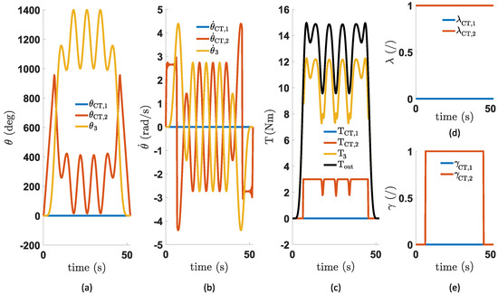 Figure 11. Overview of (a) the angle of each of the units, (b) the rotational speed of the units, (c) the torque of each unit, (d) the states of the ratchet and pawl mechanism of each unit, and (e) the states of the output clutch mechanism of each unit. These simulations were performed for a task angle with a variation of with an ideal constant torque spring. In these plots, the subscripts “CT,1” and “CT,2” indicate, respectively, the first and second constant torque unit, the subscript “3” indicates the last (continuous) unit.In (c), it can, on the other hand, be seen that the interruptions in the constant torque profile (orange line) are slightly steeper than in Figure 8, which indicates that the simulation lets the spring unwind even further beyond its reliable constant torque zone. It should be noted that these spikes in the torque profile might be beneficial according to the simulations, but, in practice, these cannot be used due to the instability/unpredictability of the torque in that rising region. The continuous unit (yellow line) has to deliver again the major part of the load, which is shown in (c). For this task, the behavior of the continuous unit changes rather quickly, which will induce extra losses.This increase in losses becomes clear when looking at Figure 12. One can see that the Joule losses themselves do not change much (from J to 12 J), but its influence on the total losses of the SPECTA is almost halved (from to . The reason is that Joule losses are always reduced significantly for SPECTA, but in more dynamic situations, the friction and gearing losses increase drastically. Here, the influence of the friction losses rises to , which is almost the same influence as the Joule losses. As such, the friction losses become twice as important as for the previous working point. The gearing losses also increase drastically, but not so much in terms of influence (from to ). Considering the explanation that was already given surrounding the friction coefficient, it becomes clear why it is preferred to use only the spring that has been coupled to the high-speed motor, as before.
 Figure 12. Overview of the different types of losses. These are (a) the Joule losses, (b) the friction losses, and (c) the gearing losses. These simulations were performed for a task angle with a variation of with an ideal constant torque spring.
4.2. Simulation Results: Case 2
As mentioned, the influence of hysteresis will be added in case 2. To observe this influence, we can consider Figure 13. In this figure, the difference in energy consumption for a SPECTA with ideal springs and a SPECTA that has springs that have hysteresis is shown when performing the same task. Here, the values of energy consumption that are positive represent the regions where the ideal spring SPECTA actuator uses less energy than the one that has hysteresis. It can be noted that the value of hysteresis was chosen since this gives a rather accurate representation of the actual value, which can be found in datasheets. When looking at Figure 13, one can see that the entire working range is better for a SPECTA with ideal springs. Hence, it can be safely said that at least for this type of task, hysteresis is not beneficial. This is a logical result, since hysteresis imposes losses on a material level.
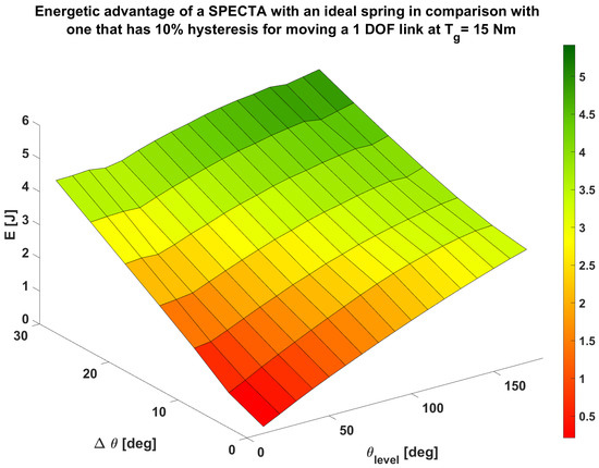
Figure 13.
Overview of the gain in total energy consumption for moving a 1 DOF link at Nm for a SPECTA actuator that is ideal in comparison to a SPECTA actuator that has springs which showcase 10% hysteresis. The values of energy consumption that are positive represent the regions where the ideal spring SPECTA actuator uses less energy than the one that has hysteresis for the same task.
It is, however, visible that the difference in energy consumption becomes clearly more apparent in the cases where and increase. This can be explained by the fact that at those working points, the trajectory becomes more dynamic (change of rotational direction for the spring), which in return imposes more losses. To analyze the effect of hysteresis even better, we will consider in detail one of the previously discussed working points so that a comparison can be made.
- First, we can consider the torque plot of Figure 14. In (b), the hysteretic behavior is clearly visible in the curve of the recruited spring (orange). The constant shifting to a certain upper and lower limit in the torque profile stems from the constant shift of the direction of rotational speed, which can be seen in (a). In (a), the rotational speed shifts rapidly from sign, which is inherent to the behavior of the pendulum task. It can be assumed that the losses which are related to torque are also influenced by this hysteresis.
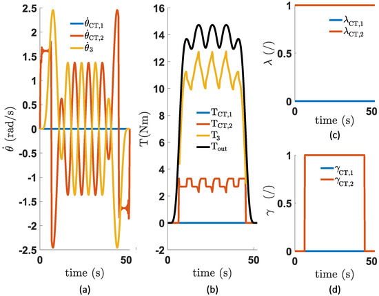 Figure 14. Overview of (a) the rotational speed of the units, (b) the torque of each unit, (c) the states of the ratchet and pawl mechanism of each unit, and (d) the states of the output clutch mechanism of each unit. These simulations were performed for a task angle with a variation of with a constant torque spring that has hysteresis. In these plots, the subscripts “CT,1” and “CT,2” indicate, respectively, the first and second constant torque unit, the subscript “3” indicates the last (continuous) unit.This influence is shown in Figure 15, where only the Joule losses (from J to J) and the gearing losses (from J to J) for the SPECTA have changed in comparison with case 1 (the case without hysteresis). The friction losses show no difference.
 Figure 15. Overview of the different types of losses. These are (a) the Joule losses, (b) the friction losses, and (c) the gearing losses. These simulations were performed for a task angle with a variation of with a constant torque spring that has hysteresis. In comparison with case 1, only the Joule losses and gearing losses have changed (increased).For the Joule losses, this is a logical result, since the torque is directly proportional to the current () and for the gearing losses, this is logical, since the term is actually torque times velocity, which results in a change in torque also changing the mechanical power and, hence, the gearing losses. This can also be correlated with the observation that increasing levels of and result in greater losses. This is because an increase in increases the overall output torque and an increase of results in a more dynamic character. Both these things increase energy consumption. Since this working point already explains everything, no more working points will be shown in detail for case 2.
5. Design of a SPECTA Actuator
In this section, the construction of the test setup will be tackled for each separate unit consecutively. For the test setup, it is chosen to use two branches with constant torque springs and one variable torque branch, which is coupled directly to the output. After these branches are tackled, the entire assembly will be handled where not only the separate units are combined, but also the load side is shown.
5.1. Constant Torque Unit with High-Speed Motor
The constant torque unit with the high-speed motor, which is shown in Figure 16, is shown first (despite it representing the second unit in the simulations) since this unit is constructed from the largest number of parts. All these distinct elements are denoted with a specific number indicated in Figure 16b. This number will also be mentioned when explaining the construction of this unit. The motors that are described in Section 3 are considered as well in order to achieve a good comparison. For this reason, we can see on the left of Figure 16 that this unit uses the high-speed motor (Maxon EC-4pole, Brushless motor, 120 W, part number 311536) to drive the constant torque spring (6), which is dimensioned to produce 0.29 Nm (Ondrives SR89). The characteristics of this motor (1) and its coupled gearbox (Maxon GP22HP, part number 370784) can be found back in Table 4. The position of this motor can be tracked by the Maxon HEDL-5540 encoder (500 PPR, part number 110516) that is integrated into the design of the motor. The motor can be decoupled from the axis of the constant torque spring by using a clutch as already mentioned in previous chapters. For this setup, an electromagnetic clutch (3) is used, since this provides an easy coupling/decoupling behavior, which is beneficial for the control. More specifically, the Electromagnetic Clutch Coupling 2.83 Nm, M.0713.2411 from Warner Electric Europe was used. It was chosen since it is both small enough and more than powerful enough to drive the constant torque spring. On the output of this unit, another electromagnetic clutch is placed (9), namely, the Electromagnetic Clutch Shaft 2.83 Nm, M.0113.2411 from Warner Electric Europe. This one is slightly different than the previous one, since it is made to couple or decouple parallel axes, which is necessary in this case, as we want to be able to decouple the spring from the output axis. This coupling is performed by a pulley (10) with a timing belt on it instead of spur gears since a belt can more easily resolve misalignment of the axes it connects.
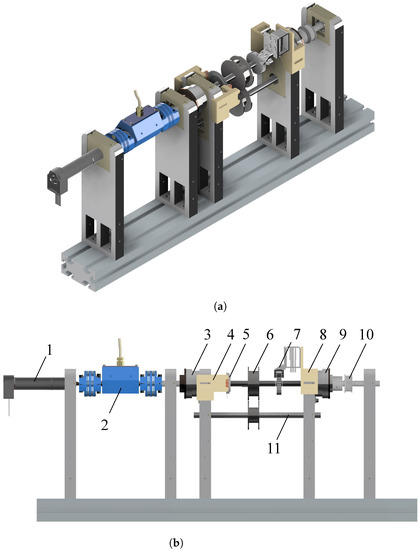
Figure 16.
Different views of the constant torque unit that is driven by a high-speed motor (EC4-Pole motor). This unit consists of (1) a DC motor, (2) a torque sensor, (3) an electromagnetic clutch on motor side, (4) a supporting piece for the encoder reader, (5) an optical encoder disc, (6) a constant torque spring, (7) a ratchet and pawl system, (8) a supporting piece with solenoid, (9) an electromagnetic clutch on load side, (10) a pulley, (11) an auxiliary axis for the constant torque spring. (a) Panoramic view of the constant torque unit with high-speed motor. (b) Side view of the constant torque unit with high-speed motor.
To obtain the exact angular position of the constant torque spring an optical encoder disc (5) is also attached to the axis of the spring. This encoder can be read by the US Digital transmissive module which is put in place with a 3D printed piece (4). It is also possible to lock the spring in a certain position even when none of the clutches are active due to a ratchet and pawl system (7). These ratchet and pawl are made with a CNC based on our own design. In order to draw the pawl into place, a solenoid is used (RS PRO Linear Solenoid, 12 V, RS-stocknr. 177-0139). This solenoid is held in place by a 3D-printed part (8). It can be noted that the storage drum of the constant torque spring is held in place using an auxiliary axis (11). To measure the exact behavior of the constant torque spring, this link is also equipped with a torque sensor (DR-2477, 0–2 Nm, Lorenz Messtechnik GmbH) that is placed between the motor and the spring. It has a measuring range of 2 Nm in order to measure precisely the spring and makes it possible to identify the gearing losses. This sensor (2) can easily be recognized since it is the blue part that is placed between the motor and the spring.
5.2. Constant Torque Unit with High-Torque Motor
The constant torque unit that is driven by the high-torque motor (unit 1 in the simulations), which is shown in Figure 17 uses a Maxon EC 60 Flat, Brushless motor (200 W, part number 614949) without any coupled gearbox, but with an integrated encoder (Maxon Encoder MILE, 2048 PPR, part number 651166). In this branch, no torque sensor is placed, since the high-torque motor does not need any gearbox and, hence, the torque can simply be measured by the motor current. Except for a change in motor and the absence of a torque sensor, this entire unit is similar to the constant torque unit which is driven by the high-speed motor and, therefore, will not be explained again in detail.
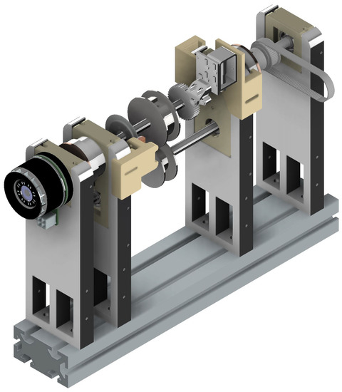
Figure 17.
Panoramic view of the constant torque unit that is driven by a high-torque motor (EC Flat motor). Only encoders are included in this unit as measuring tools, no torque sensors.
5.3. Continuous Torque Unit and Output Load
The last branch, which provides continuous torque (variable torque unit) and is coupled axially to the output load, is shown in Figure 18. For this last branch, again some numbers will be indicated throughout the explanation of the individual parts. Those numbers correspond to the ones that are indicated in Figure 18b. On the left, we see again the EC4-Pole motor (1) and its gearbox. To couple this motor to the output axis (3), a connection part (2) is 3D-printed which on the motor side has a set-screw to attach and on the output axis side—a special shape, such that it is rigidly connected. This rigid connection with the output axis is possible because it has a slotted design. This makes it also possible to easily fix the belt pulleys (4). Afterwards, the output axis is coupled to a gearbox (6) with another coupling piece (5), this time in aluminum. The gearbox itself (Neugart PLFE064, ratio 1:10) allows to produce the entire output load, since the output of this gearbox, i.e., the region between (6) and (8), is also the output of the SPECTA.
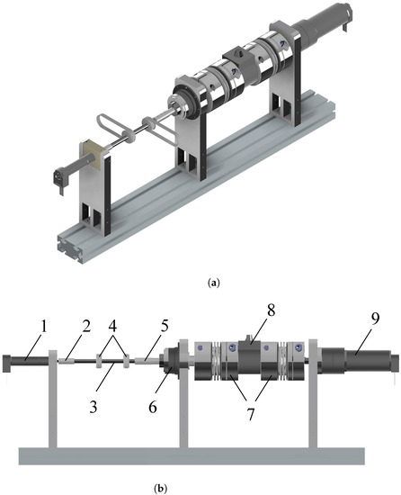
Figure 18.
Different views of the output branch, which contains both the variable torque unit and the output load, which are linked together. This unit consists of (1) a DC motor that is driving the variable torque unit, (2) a connection piece, (3) the output axis, (4) two pulleys to couple the other units to the output axis, (5) a connection piece, (6) a gearbox, (7) bellow couplings, (8) a torque sensor, (9) the load motor. (a) Panoramic view of the output branch (variable torque unit and output load). (b) Side view of the output branch.
For the load, one motor is added in combination with a gearbox (9)—these are more specifically a RE50, 200W DC Maxon motor and the Maxon GP 62A gearbox with a transmission ratio of 1:139. The details of these components are listed below in Table 6. In order to measure correctly the torques that occur at the output of the SPECTA, a torque sensor (8) is also added that has a range of 50 Nm (DRBK Model-II, 0–50 Nm, ETH Messtechnik GmbH), which is coupled to the rest of the setup by means of metal KB4 bellow couplings (7).
5.4. Complete Assembly
When combining all parts, attention should be given to the direction in which the constant torque delivers positive torque. For this setup, it is chosen to turn constant torque unit 1 such that both constant torque units can deliver positive torque. This can be seen in Figure 19 where the entire mechanical part is shown.
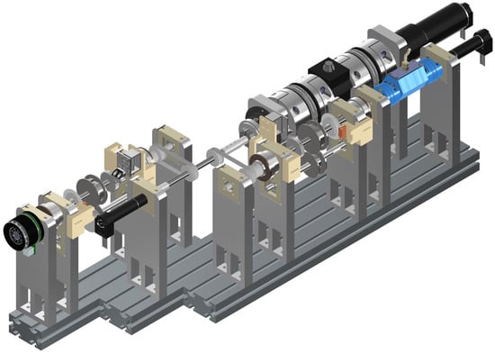
Figure 19.
Panoramic view of the complete test bench, which contains both constant torque units and the variable torque unit with output. In this setup, one of the constant torque units is turned such that both can deliver positive torque.
5.5. Control System
The test setup consists not only of the mechanical part, but also of the control part. Briefly, it can be said that each of the 4 motors is driven by an ESCON servo controller as this is the only Maxon motor controller that can work with analog signals (which is necessary when working with Speedgoat). The exact used controllers are the Maxon ESCON 50/5 (part number 409510) for the stiff, continuous torque motor, and the Maxon ESCON 70/10 (part number 422969) for all the other motors. All these motors are position-controlled, except for the load motor which is torque-controlled, with the use of the output torque sensor. For the driver of the stiff motor, current control is used as a control method, whereas the other drivers are velocity-controlled. The control mode of the stiff motor and the load motor must be different, otherwise, they will only work against each other when a small measurement error occurs.
The analog signals that can be emitted from these motor controllers are coupled to the Speedgoat Real-Time pc by connecting them to the IO133 Module. This same module is also used to send signals in the other direction to control the motors. Another module is also connected to the Real-Time pc, namely, the Speedgoat IO306-25k module, which is used as quadrature encoder for all encoder signals in the setup in order to obtain an accurate representation of each position that is being measured. In the last phase, the Real-Time PC is coupled to a simulink scheme, which will be discussed more elaborately in the following section. In this simulink scheme, the control is designed to interact with the physical set-up. The complete setup, hence both mechanical and control parts, are shown in Figure 20.
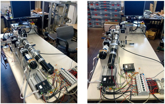
Figure 20.
View of the experimental SPECTA set-up.
In Figure 21 the simulink script is shown that was used for the tests. In this scheme, some white blocks can be seen—these are data files that are generated by the simulations (in order to achieve an optimal trajectory). These data are used as input on several parts of the simulink scheme such that the correct inputs are provided. To determine the state of the clutches, the data blocks ’Psi_1’, ’Gamma_1’, ’Psi_2’, and ’Gamma_2’ are used. For the positions of the SPECTA motors and the torque of the load motor, the blocks ’Theta_M1’,’Theta_M2’,’Theta_Mstiff’, and ’Torq_Mload’ are used.
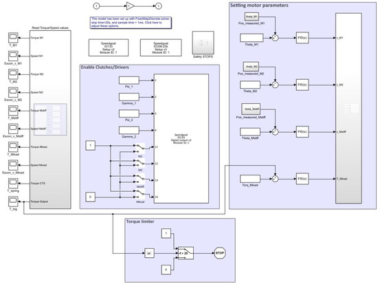
Figure 21.
Overview of the simulink script that was used to perform the tests. All motors were separately tuned and some safety mechanisms were added.
In simulink, every motor was tuned with a PID controller such that they could work properly at their operational speed. To do so, the working frequencies were retrieved with an FFT that was applied to the input data that were generated by the simulations. For all motors related to the SPECTA, position control was used with a quadrature encoder signal as feedback. The load motor was torque-controlled, whereby the feedback was given by the torque sensor of 50 Nm, which also measured the output.
In this simulink script, some safety measures were added to exclude potential breaks of the system. Thus, aside from the conventional emergency stop, a safety measure was also introduced such that the constant torque springs could not turn in the other direction when they were completely unwound and a safety was also placed on the output torque.
6. Experimental Validation
6.1. Hysteresis Test of the Springs
Constant torque springs feature some hysteresis, which needs to be tested to observe its influence. This hysteresis is usually around as shown in Figure 22. In this figure, the torque–deflection curve has been experimentally measured for a constant torque spring of Nm.
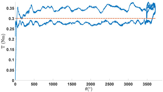
Figure 22.
Experimental tests of the working range of a constant torque spring that is dimensioned to deliver 0.3 Nm. This theoretical value is indicated in orange, whereas the measured torque is indicated in blue.
This figure also shows that some ripple is always present in the data, which is unavoidable for each constant torque mechanism. In Figure 22, it can be seen that, in the beginning, an increasing curve is present where the value of the constant torque spring is difficult to predict. This is, however, not an undesired result, as it is always recommended to only use a constant torque spring in its region after 1.25 turns (=).
6.2. Trajectory Tracking
To validate the built setup and simulations, tests were performed for a pendulum task at Nm with a task angle and a variation of . For these tests, it was chosen to show a task when only the high-torque motor works (i.e., unit 1).
In Figure 23 the results of this test are shown. Here, the torques for each of the driving units, i.e., motor 1 (which is the high-torque motor) and the stiff motor (which is the motor of the continuous output unit), are shown together with the torque and velocity values at the output. From these plots, it can be seen that the output is tracked rather well, even though only a PID controller was placed for the torque control of the load motor. The flanks of the trajectory are tracked rather nicely, but the values in the middle are not exactly the same. This performance could, however, not be improved with only PID control.
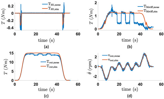
Figure 23.
Overview of the motor torques (after the gearbox) of (a) the first (high-torque motor) unit and (b) the last (continuous torque) unit, together with (c) the torque and (d) velocity values at the output. For each plot, both the simulated (orange) and measured (blue) data are included. These data were retrieved when performing/simulating a pendulum task for a task angle and a variation of .
When consideting the individual motors, it is clear motor 1 tracks its given trajectory well, but the same cannot be said of the motor at the output branch (). This is because this motor is position-controlled and, therefore, already takes the effect of the constant torque spring into account, which most likely shows a different hysteretic behavior than that included in the simulations. However, a part of the lower generated torque also stems from the fact that at the output, the measured torque is also slightly lower than what was simulated. To analyze the electrical energy consumption, the following equation should be used as a foundation:
It is shown in Figure 24 that the individual voltages and currents of the simulated motors correspond rather to with the experimental data. For motor 1, the behavior seems similar, however, since only peaks needed to be generated (the spring is in this trajectory mainly charged by the output), every little change has a big impact on the total consumption. When looking in detail, it can be seen that for the current values (a), the peaks of the measured data continue until A, whereas the simulated currents only reach A. This indicates that the real spring delivers slightly more torque than the simulated one, which will lead to greater energy savings in the middle area of the task trajectory (where the spring is connected to the output). On the other hand, the measured voltage of motor 1 (b) is slightly lower than its simulated counterpart ( V peak vs. V). This indicates that the motor was charging the spring more slowly before it was coupled to the output. This difference in peak values, especially for the voltage, together with some disturbance at the end of the trajectory, allows to see in (c) that the consumed energy of the experimental setup is lower than the simulated one. After the short, initial motor charging, the measured motor has consumed A, whereas the simulated one has consumed J. At the end, when the spring is released from the output, one can also see that the experimental data show that motor 1 gains J from the output, whereas the simulated motor consumes the same amount. This is most likely due to the fact that, at that specific moment, the clutch of the experimental setup does not open instantly, which results in the load and the motor making contact at an unplanned moment. This cannot happen in simulations, since they represent ideal cases.
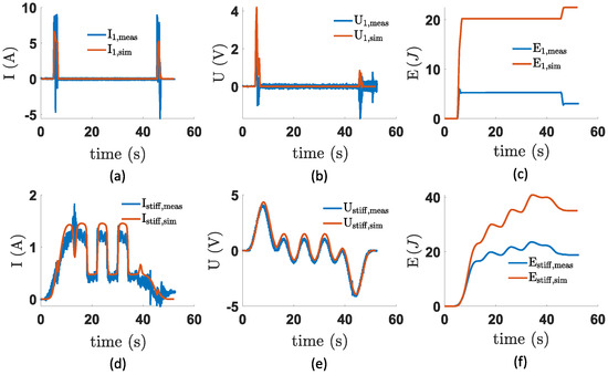
Figure 24.
Overview of (a) the motor current and (b) voltage of the first unit, together with (c) its electrical energy consumption. The (d) motor current, (e) voltage, and (f) electrical energy consumption of the last (continuous torque) unit are also shown. For each plot, both the simulated (orange) and measured (blue) data are plotted. These data were retrieved when performing/simulating a pendulum task for a task angle and a variation of .
When looking at the current and voltage values of (d)–(e), it is clear that the curves fit well, although the experimental values are always slightly lower, which is most likely caused by poor prediction of the exact torque value of the constant torque spring. This, in turn, results in a lower measured energy consumption of the stiff motor unit (f) than expected from the simulations ( J vs. 35 J). As energy recuperation already happens for motor 1 during the test (and not during simulation), the stiff motor recuperates less energy at the end of the trajectory in comparison with its simulated counterpart.
After putting all these individual consumptions together, the total consumed energy can be calculated, which is shown in Figure 25. Since both motors have consumed less than their simulated versions, the total energy consumption also decreases for the experimental values.
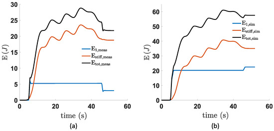
Figure 25.
Overview of both the measured (a) and simulated (b) energy losses of the individual units together with the total consumed energy. These data were retrieved when performing/simulating a pendulum task for a task angle and a variation of .
For the measured SPECTA (a), the total energy consumption becomes J and that of the simulated (b)— J. To draw some more in-depth conclusions about the practical working of the SPECTA and to retrieve some detailed efficiency and energy recuperation data, the design should first be optimized before it is tested. Otherwise, some false conclusions could be made as a consequence of a non-ideal design. This is, however, to be attempted in future work.
7. General Conclusions and Discussion
7.1. Conclusions from the Simulation Results
Based on the simulations that were performed considering a pendulum task for a broad range of values (variation in , and ), it was found that SPECTA behaves better than its stiff equivalent in many cases and especially for increasing values of the gravitational torque. The only exceptions to this are the most dynamic tasks (i.e., high and ).
It is surprising that SPECTA was indeed better for a lot of cases, since it was not optimized, on a hardware level, for the tasks it had to perform. The hardware was not optimized because we wanted to investigate which type of motor (high-torque or high-speed) would be preferable in this actuator. This led to the choice of using two constant torque units, from which one uses a high-torque motor without any gearing (such that the gearing losses would be excluded) and the other uses a high-speed motor with a gearing that has poor efficiency (to see what happens when gearing losses are as bad as possible).
From the simulations conducted in this paper, it was found that the high-torque motors are not preferred for two reasons. First of all, high-torque motors have a friction coefficient, , which is inherently significantly higher than the one of high-speed motors. This results in friction losses which become more dominant in the total losses in comparison to the gearing losses of the high-speed motor, even though the gearing efficiency of the used high-speed motor was rather low.
Secondly, high-torque motors need to use a higher current to reach the same torque level, which immediately results in greater Joule losses. It could be stated that in the simulations that were performed, the high-speed motor could deliver more torque in combination with its gearbox than the high-torque motor, which would result automatically in smaller Joule losses. However, when making the calculation with a gearing that corresponds exactly to what the high-torque motor produces, the necessary current will still be lower for the high-speed motor than for the high-torque one.
As a result, the simulations always pointed out that it is preferable to only use the spring that is being charged by the high-speed motor. This implies that the SPECTA actuator is performing even better than initially thought, as the equivalent stiff motor was actually not equivalent due to the fact that one of the constant torque units was not used.
It was also found that the overall effect of hysteresis on the energy consumption is minor and it becomes only noticeable in highly dynamic situations. This is logical, since highly dynamic situations imply a lot of changes in the rotational direction of the spring and, consequently, the torque it produces. It can also be noted that hysteresis only has an influence on the Joule and gearing losses, and not on the friction losses. The reason behind this can be easily found when looking at the equations that describe each of the separate losses.
7.2. Conclusions from the Experimental Results
The influence of the hysteresis in the constant torque springs has also been studied by measuring the torque-angle characteristics of the used constant torque springs.
This validated that the hysteresis remained indeed almost always in the theoretical -range. The behavior is, however, less flat than what was observed in the (theoretical) simulation analysis, which might in some very dynamic cases give a slight change in what was predicted for the simulations. This less flat behavior in itself is most likely caused by some minor friction that can stem from, e.g., the bearings. Especially with a spring that has relatively low torque, these influences are visible. Hence, it is assumed that in constant torque springs with a higher torque level, the hysteresis curve will be flatter and, therefore, will become more in line with the simulation results.
Regarding the experiments of the actuator itself, it can be said that the experiments showed a good agreement with the simulated input data. The main observed differences between simulations and experiments are twofold. First, the torque value of the constant torque spring differs slightly from the simulations. This led to a different requirement for motor power when charging the spring. Secondly, the switching times of the clutches could not be regulated as strictly as in the simulations. The load was thus briefly in contact with the driving motor of the spring during (dis-)engagement. This changed the energy consumption from the predicted behavior.
This could be solved, for example, by implementing a more sophisticated control, i.e., some form of hysteresis compensation, or by making sure that all equipment has a decently large bandwidth, such that the motors can track the input data even better. This is, however, a task for future work.
7.3. Discussion
Throughout this work, the need for a novel compliant actuation technology, together with the mathematical development of the SPECTA and eventually its practical build, is explained and realized. From all the experiments, results, and analyses, it can be stated that SPECTA is an energetically interesting actuation technology to use, especially in high-load situations, since then the Joule losses are dominant. It is also found that the best performance for these actuators can be achieved when using high-speed motors with efficient gearing. Hence, everything is developed to start comparing SPECTA with the best current compliant actuators.
Future work should consist of optimizing, both practically and theoretically, the current SPECTA model, such that it can be compared in a suitable way with the current generation of compliant actuators, such as SPEA. In [39], it was already proven throughout simulations that using constant torque springs is beneficial. However, since now in this work clutches are also added to the SPECTA concept, an even greater gain should be expected. This remains, however, to be verified.
Author Contributions
Conceptualization, E.S. and D.L.; Data curation, E.S.; Formal analysis, E.S.; Investigation, E.S.; Methodology, E.S.; Project administration, B.V.; Supervision, R.G.F., B.V. and D.L.; Visualization, J.L.; Writing—original draft, E.S.; Writing—review & editing, J.L., S.C., P.L.G., T.V. and B.V. All authors have read and agreed to the published version of the manuscript.
Funding
This research was partially funded by FWO research project 1505820N.
Acknowledgments
Elias Saerens, Stein Crispel, and Julie Legrand are all affiliated with the Research Foundation Flanders—Fonds voor Wetenschappelijk Onderzoek (FWO) Vlaanderen.
Conflicts of Interest
The authors declare no conflict of interest.
References
- ATLAS DRC Robot Is 75 Percent New, Completely Unplugged. 2021. Available online: https://spectrum.ieee.org/atlas-drc-robot-is-75-percent-new-completely-unplugged (accessed on 8 May 2021).
- Ficht, G.; Behnke, S. Bipedal Humanoid Hardware Design: A Technology Review. Curr. Robot. Rep. 2021, 2, 201–210. [Google Scholar] [CrossRef]
- Table of Spot Robot Specifications. 2021. Available online: https://support.bostondynamics.com/s/article/Robot-specifications (accessed on 8 May 2021).
- Stretch Is Boston Dynamics’ Take on a Practical Mobile Manipulator for Warehouses. 2021. Available online: https://spectrum.ieee.org/automaton/robotics/industrial-robots/stretch-is-boston-dynamics-take-on-a-practical-mobile-manipulator-for-warehouses (accessed on 8 May 2021).
- Kashiri, N.; Abate, A.; Abram, S.J.; Albu-Schaffer, A.; Clary, P.J.; Daley, M.; Faraji, S.; Furnemont, R.; Garabini, M.; Geyer, H.; et al. An overview on principles for energy efficient robot locomotion. Front. Robot. AI 2018, 5, 129. [Google Scholar] [CrossRef] [PubMed] [Green Version]
- Pratt, G.A.; Williamson, M.M. Series elastic actuators. In Proceedings of the 1995 IEEE/RSJ International Conference on Intelligent Robots and Systems, Human Robot Interaction and Cooperative Robots, Pittsburgh, PA, USA, 5–9 August 1995; Volume 1, pp. 399–406. [Google Scholar]
- Hitt, J.K.; Sugar, T.G.; Holgate, M.; Bellman, R. An active foot-ankle prosthesis with biomechanical energy regeneration. J. Med. Devices 2010, 4, 011003. [Google Scholar] [CrossRef]
- Verstraten, T.; Beckerle, P.; Furnémont, R.; Mathijssen, G.; Vanderborght, B.; Lefeber, D. Series and parallel elastic actuation: Impact of natural dynamics on power and energy consumption. Mech. Mach. Theory 2016, 102, 232–246. [Google Scholar] [CrossRef]
- de Gea Fernández, J.; Yu, B.; Bargsten, V.; Zipper, M.; Sprengel, H. Design, Modelling and Control of Novel Series-Elastic Actuators for Industrial Robots. Actuators 2020, 9, 6. [Google Scholar] [CrossRef] [Green Version]
- Beckerle, P.; Stuhlenmiller, F.; Rinderknecht, S. Stiffness control of variable serial elastic actuators: Energy efficiency through exploitation of natural dynamics. Actuators 2017, 6, 28. [Google Scholar] [CrossRef] [Green Version]
- Lee, C.; Kwak, S.; Kwak, J.; Oh, S. Generalization of series elastic actuator configurations and dynamic behavior comparison. Actuators 2017, 6, 26. [Google Scholar] [CrossRef]
- Grimmer, M.; Eslamy, M.; Seyfarth, A. Energetic and peak power advantages of series elastic actuators in an actuated prosthetic leg for walking and running. Actuators 2014, 3, 1–19. [Google Scholar] [CrossRef] [Green Version]
- Jafari, A.; Tsagarakis, N.G.; Caldwell, D.G. A novel intrinsically energy efficient actuator with adjustable stiffness (AwAS). IEEE/ASME Trans. Mechatron. 2011, 18, 355–365. [Google Scholar] [CrossRef]
- Visser, L.C.; Carloni, R.; Stramigioli, S. Energy-efficient variable stiffness actuators. IEEE Trans. Robot. 2011, 27, 865–875. [Google Scholar] [CrossRef]
- Kim, B.S.; Song, J.B. Design and control of a variable stiffness actuator based on adjustable moment arm. IEEE Trans. Robot. 2012, 28, 1145–1151. [Google Scholar]
- Tonietti, G.; Schiavi, R.; Bicchi, A. Design and control of a variable stiffness actuator for safe and fast physical human/robot interaction. In Proceedings of the of the 2005 IEEE International Conference on Robotics and Automation, Barcelona, Spain, 18–22 April 2005; pp. 526–531. [Google Scholar]
- Grioli, G.; Wolf, S.; Garabini, M.; Catalano, M.; Burdet, E.; Caldwell, D.; Carloni, R.; Friedl, W.; Grebenstein, M.; Laffranchi, M.; et al. Variable stiffness actuators: The user’s point of view. Int. J. Robot. Res. 2015, 34, 727–743. [Google Scholar] [CrossRef] [Green Version]
- Wolf, S.; Grioli, G.; Eiberger, O.; Friedl, W.; Grebenstein, M.; Höppner, H.; Burdet, E.; Caldwell, D.G.; Carloni, R.; Catalano, M.G.; et al. Variable stiffness actuators: Review on design and components. IEEE/ASME Trans. Mechatron. 2016, 21, 2418–2430. [Google Scholar] [CrossRef]
- Van Ham, R.; Vanderborght, B.; Van Damme, M.; Verrelst, B.; Lefeber, D. MACCEPA, the mechanically adjustable compliance and controllable equilibrium position actuator: Design and implementation in a biped robot. Robot. Auton. Syst. 2007, 55, 761–768. [Google Scholar] [CrossRef]
- Wolf, S.; Hirzinger, G. A new variable stiffness design: Matching requirements of the next robot generation. In Proceedings of the 2008 IEEE International Conference on Robotics and Automation, Pasadena, CA, USA, 19–23 May 2008; pp. 1741–1746. [Google Scholar]
- Vanderborght, B.; Tsagarakis, N.G.; Van Ham, R.; Thorson, I.; Caldwell, D.G. MACCEPA 2.0: Compliant actuator used for energy efficient hopping robot Chobino1D. Auton. Robot. 2011, 31, 55. [Google Scholar] [CrossRef]
- Bicchi, A.; Tonietti, G.; Bavaro, M.; Piccigallo, M. Variable stiffness actuators for fast and safe motion control. In Proceedings of the Robotics Research. The Eleventh International Symposium, Siena, Italy, 19–22 October 2005; pp. 527–536. [Google Scholar]
- Awad, M.I.; Gan, D.; Thattamparambil, J.; Stefanini, C.; Dias, J.; Seneviratne, L. Novel passive discrete variable stiffness joint (pDVSJ): Modeling, design, and characterization. In Proceedings of the 2016 IEEE International Conference on Robotics and Biomimetics (ROBIO), Qingdao, China, 3–7 December 2016; pp. 1808–1813. [Google Scholar]
- Verstraten, T.; López-García, P.; Lenaerts, B.; Mrak, B.; Lefeber, D.; Vanderborght, B. Improving the performance of industrial machines with variable stiffness springs. Mech. Based Des. Struct. Mach. 2020, 50, 115–134. [Google Scholar] [CrossRef]
- Ducastel, V.; Langlois, K.; Rossini, M.; Grosu, V.; Vanderborght, B.; Lefeber, D.; Verstraten, T.; Geeroms, J. SMARCOS: Off-the-Shelf Smart Compliant Actuators for Human-Robot Applications. Actuators 2021, 10, 289. [Google Scholar] [CrossRef]
- Mettin, U.; La Hera, P.X.; Freidovich, L.B.; Shiriaev, A.S. Parallel elastic actuators as a control tool for preplanned trajectories of underactuated mechanical systems. Int. J. Robot. Res. 2010, 29, 1186–1198. [Google Scholar] [CrossRef]
- Roozing, W.; Li, Z.; Medrano-Cerda, G.A.; Caldwell, D.G.; Tsagarakis, N.G. Development and control of a compliant asymmetric antagonistic actuator for energy efficient mobility. IEEE/ASME Trans. Mechatron. 2015, 21, 1080–1091. [Google Scholar] [CrossRef]
- Mazumdar, A.; Spencer, S.J.; Hobart, C.; Salton, J.; Quigley, M.; Wu, T.; Bertrand, S.; Pratt, J.; Buerger, S.P. Parallel elastic elements improve energy efficiency on the STEPPR bipedal walking robot. IEEE/ASME Trans. Mechatron. 2017, 22, 898–908. [Google Scholar] [CrossRef]
- Plooij, M.; Wisse, M. A novel spring mechanism to reduce energy consumption of robotic arms. In Proceedings of the 2012 IEEE/RSJ International Conference on Intelligent Robots and Systems, Algarve, Portugal, 7–12 October 2012; pp. 2901–2908. [Google Scholar]
- Häufle, D.F.; Taylor, M.; Schmitt, S.; Geyer, H. A clutched parallel elastic actuator concept: Towards energy efficient powered legs in prosthetics and robotics. In Proceedings of the 2012 4th IEEE RAS & EMBS International Conference on Biomedical Robotics and Biomechatronics (BioRob), Rome, Italy, 24–27 June 2012; pp. 1614–1619. [Google Scholar]
- Mathijssen, G.; Lefeber, D.; Vanderborght, B. Variable recruitment of parallel elastic elements: Series–parallel elastic actuators (SPEA) with dephased mutilated gears. IEEE/ASME Trans. Mechatron. 2014, 20, 594–602. [Google Scholar] [CrossRef]
- Mathijssen, G.; Brackx, B.; Van Damme, M.; Lefeber, D.; Vanderborght, B. Series-Parallel Elastic Actuation (SPEA) with intermittent mechanism for reduced motor torque and increased efficiency. In Proceedings of the 2013 IEEE/RSJ International Conference on Intelligent Robots and Systems, Tokyo, Japan, 3–7 November 2013; pp. 5841–5846. [Google Scholar]
- Mathijssen, G.; Furnémont, R.; Verstraten, T.; Brackx, B.; Premec, J.; Jiménez, R.; Lefeber, D.; Vanderborght, B. +SPEA introduction: Drastic actuator energy requirement reduction by symbiosis of parallel motors, springs and locking mechanisms. In Proceedings of the 2016 IEEE International Conference on Robotics and Automation (ICRA), Stockholm, Sweden, 16–21 May 2016; pp. 676–681. [Google Scholar] [CrossRef]
- Mathijssen, G.; Furnémont, R.; Verstraten, T.; Espinoza, C.; Beckers, S.; Lefeber, D.; Vanderborght, B. Study on electric energy consumed in intermittent series–parallel elastic actuators (iSPEA). Bioinspir. Biomim. 2017, 12, 036008. [Google Scholar] [CrossRef]
- Furnémont, R.; Mathijssen, G.; Verstraten, T.; Jiménez, R.; Lefeber, D.; Vanderborght, B. Novel control strategy for the+ SPEA: A redundant actuator with reconfigurable parallel elements. Mechatronics 2018, 53, 28–38. [Google Scholar] [CrossRef]
- Mathijssen, G.; Furnémont, R.; Saerens, E.; Lefeber, D.; Vanderborght, B. Discrete binary muscle-inspired actuation with motor unit overpowering and binary control strategy. In Proceedings of the 2017 IEEE/RSJ International Conference on Intelligent Robots and Systems (IROS), Vancouver, BC, Canada, 24–28 September 2017; pp. 2128–2134. [Google Scholar]
- Mathijssen, G.; Furnémont, R.; Saerens, E.; Garabini, M.; Catalano, M.G.; Lefeber, D.; Bicchi, A.; Vanderborght, B. Novel lockable and stackable compliant actuation unit for modular+ SPEA actuators. IEEE Robot. Autom. Lett. 2019, 4, 4445–4451. [Google Scholar] [CrossRef]
- Mathijssen, G.; Cherelle, P.; Lefeber, D.; Vanderborght, B. Concept of a series-parallel elastic actuator for a powered transtibial prosthesis. Actuators 2013, 2, 59–73. [Google Scholar] [CrossRef] [Green Version]
- Saerens, E.; Furnémont, R.; Ducastel, V.; Crispel, S.; Vanderborght, B.; Lefeber, D. Energetic Advantages of Constant Torque Springs in Series Parallel Elastic Actuators. In Proceedings of the 2019 IEEE/ASME International Conference on Advanced Intelligent Mechatronics (AIM), Hong Kong, China, 8–12 July 2019; pp. 62–67. [Google Scholar]
- Plooij, M.; Mathijssen, G.; Cherelle, P.; Lefeber, D.; Vanderborght, B. Lock your robot: A review of locking devices in robotics. IEEE Robot. Autom. Mag. 2015, 22, 106–117. [Google Scholar] [CrossRef]
- Furnémont, R. Design Principles and Trajectory Optimizations for Series-Parallel Elastic Actuators to Improve Energy Efficiency. Ph.D. Thesis, Vrije Universiteit Brussel, Brussel, Belgium, 2019. [Google Scholar]
- Rao, A.V. A survey of numerical methods for optimal control. Adv. Astronaut. Sci. 2009, 135, 497–528. [Google Scholar]
- Bryson, A., Jr.; Ho, Y. Applied Optimal Control; Hemisphere Publishing Corporation: New York City, NY, USA, 1975. [Google Scholar]
Publisher’s Note: MDPI stays neutral with regard to jurisdictional claims in published maps and institutional affiliations. |
© 2022 by the authors. Licensee MDPI, Basel, Switzerland. This article is an open access article distributed under the terms and conditions of the Creative Commons Attribution (CC BY) license (https://creativecommons.org/licenses/by/4.0/).