Abstract
Topology and shape optimization are still rarely applied to problems in electromagnetic design due to the computational complexity and limited commercial tooling, even though components such as electrical motors, magnetic springs or magnetic bearings could benefit from it, either to improve performance (reducing torque ripple and losses through shaping harmonic content in back electromotive force) or reduce the use of rare-earth materials. Magnetic springs are a fatigue free alternative to mechanical springs, where shape optimization can be exploited to a great degree—allowing for advanced non-linear stiffness characteristic shaping. We present the optimization methodology relying on a combination of several approaches for characteristic shaping of magnetic springs through either a modular design approach based on: (i) Fourier order decomposition; (ii) breaking conventional design symmetry; or (iii) free shaping of magnets through deviation from a nominal design using problem formulations such as spline and polynomials for material boundary definitions. Each of the parametrizations is formulated into a multi-objective optimization problem with both performance and material cost, and solved using gradient free optimization techniques (direct search, genetic algorithm). The methodology is employed on several benchmark problems—both academic and application inspired magnetic spring torque characteristic requirements. The resulting designs fit well with the requirements, with a relatively low computational cost. As such, the methodology presented is a promising candidate for other design problems in 2D shape optimization in electrical motor research and development.
1. Introduction
Magnetic springs are an alternative to mechanical springs in applications that require long lifetime with no fatigue failure. Recent efforts introduced them to the industrial and academic audiences as a promising technology for torque ripple reduction in highly dynamic motion systems [1,2]. Although the previously demonstrated torsional magnetic springs typically have sinusoidal torque characteristics, for reasons of cost efficiency, there are many motion systems in the industrial practice that could benefit from a deviation from it. Two good examples, both highly present in reciprocating machinery are oscillating loads driven by: (i) conjugate cam-followers; and (ii) a crank-rocker mechanism. In cam-followers, the dwell of the cam causes a quasi-sinusoidal characteristic to only be required for a fraction of the full cam rotation, while in a crank-rocker, the non-linear kinematics can add harmonic content to the required torque, due to the deviation from ideal transmission angle of .
Other applications with reciprocating mechanical loads and other torque ripple phenomena can benefit from the use of magnetic springs:
- weaving looms and other textile machinery featuring reciprocating motion;
- agricultural machines, e.g., reciprocating moving parts in combine harvesters;
- metal forming machines such as punching and bending machines;
- packaging machinery;
- pick and place robots;
- humanoid robots and exoskeletons;
- torque ripple in drivetrains with gears due to the variable gear meshing;
- internal combustion engines, particularly in hybrid drivetrain;
- fans, blowers and centrifugal compressors due to aerodynamic effects;
- other compressors and pumps, such as centrifugal, rotary lobe, piston, screw etc.;
- wind turbines due to pole shade effect.
An exhaustive explanation of the list above is available in the conclusive chapter of ref. [1]. In the present paper, we highlight the design methodologies for tailoring the magnetic spring characteristics to the application needs. Together with the methodological contribution, this article aims to identify the intrinsic benefits and limitations of each method and presents a benchmark on a real design problem performed for a textile machinery application.
It is worth mentioning that the magnetic springs are topologically identical to passive magnetic bearings (PMB) and magnetic clutches. The main difference is the magnetic load point of the permanent magnets: in a magnetic spring, the magnets are more typically loaded over the entire B-H curve repeatedly in each driving cycle, while for PMB and the magnetic clutches, the operating point remains constant for constant mechanical load.
Two approaches were developed for the synthesis of a non-sinusoidal characteristic in magnetic springs which would better fit typical torque requirements as shown in Figure 1. The first approach relies on an existing workflow presented in [2,3] and is discussed in Section 2.1. Within this approach, multiple magnetic springs with sinusoidal characteristic and different pole pair numbers are combined into a Fourier series of the desired torque profile. The second approach, or rather set of approaches, presented in Section 2.2, explores multiple shape optimization techniques, that is, reshaping the magnets and back iron of the magnetic spring to achieve the desired torque characteristic.
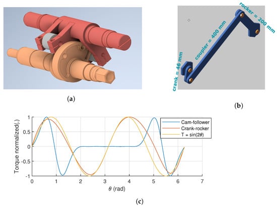
Figure 1.
Magnetic spring characteristic requirements for highly dynamic reciprocating mechanisms. (a) Conjugate cam-follower. (b) Crank-rocker. (c) Resulting torque characteristics.
2. Methodology
2.1. Decomposition Based Approach
The proposed spring consists of multiple magnetic springs with rotors rigidly coupled to the drivetrain shaft and the stator rigidly connected to the housing of the drivetrain. This allows us to compensate for multiple torque orders with various amplitudes and phase alignments. Selecting the pole pair number of the magnetic spring n determines the frequency of the spring torque relative to the shaft rotation, while the angular orientation of the spring stator defines the phase of the superimposed sinusoidal torque (Equation (1)) as schematically illustrated in Figure 2. This formulation is coincidentally equivalent to the Fourier series decomposition with the constant component of a desired torque characteristic.
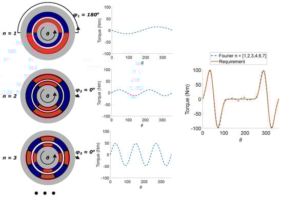
Figure 2.
Decomposition based approach for multiple order magnetic spring.
Using the above mentioned Fourier decomposition approach, it is possible to investigate the optimal tuning of each of the magnetic spring orders that form the harmonic magnetic spring for a given design problem in the system optimization phase. The decomposition approach has two distinct benefits:
- Manufacturing simplicity of the magnetic springs;
- Improved performance at compensating specific isolated orders, e.g., in applications where specific higher orders can be related to the individual physical effects such as gear meshing, ICE firing order, etc.
Equally, we can observe several downsides:
- Higher material cost, i.e., more rare-earth magnets required for same equivalent energy content as depending on the phase alignment and order, separate order torques partially cancel out;
- higher mechanical complexity, i.e., multiple stators and rotors need to be manufactured and assembled together;
- Difficulty of capturing all characteristics with limited number of orders (<3);
- Issues with high gradients torque characteristic due to the Gibbs phenomenon even with higher order.
2.2. Shape Optimization
In a different approach, it is also possible to change the spring characteristic by directly shaping the magnets and the back iron of a single magnetic spring. Such a shape optimization problem is considered more challenging, both for reasons of optimization complexity and manufacturability. The main arguments for shape optimized designs, some examples of which can be seen in Figure 3), are the potential for a more efficient use of costly magnetic material, with a characteristic better tailored to the application needs, higher compactness, reduced mechanical complexity, and potentially better system performance.
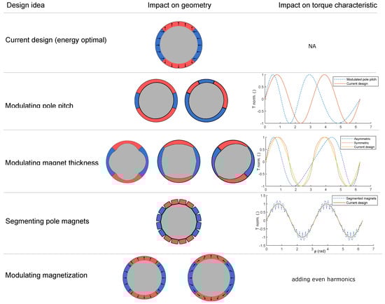
Figure 3.
Magnet shape variations based on engineering insight, with corresponding torque characteristics.
Relying on pre-existing mature engineering software was not possible for this highly specific challenge. Several methods were, thus, developed in parallel in two different software tools. FEMM (Finite Element Method Magnetics) [4] is used for magnetostatic finite element simulations of the geometry both within SyMspace™ [5] and . The latter is an extension of the previously presented Drivetrain Co-design toolchain [6] developed by Flanders Make where package NOMAD (Nonlinear Optimization with Mesh Adaptive Direct Search algorithm) [7] is used for blackbox optimization.
We propose to use one overarching approach to compare these different shaping methodologies. Figure 4 gives an overview of this unified approach. Starting from the magnetic spring requirements, the magnetic spring geometry is optimized, given a physical parameterization. The goal is to match the torque profile obtained from a system design analysis, for example, system dynamics simulation or perhaps existing operational torque measurements. In order to do so, we approximate the magnetic spring radial flux geometry and the resulting magnetic field as a 2D magnetostatic FEM problem. The cost function is then given by:
where is the FEM 2D torque of a 1 mm slice, l is the axial length and p is the parameter set describing the spring geometry. This approach builds on previous publication [2], and extends it for spring characteristic shaping.
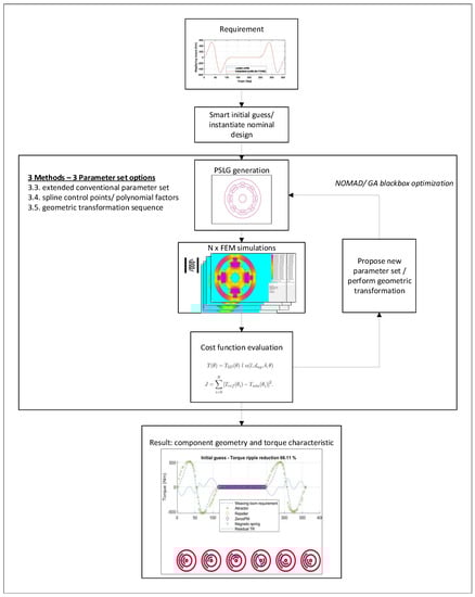
Figure 4.
Overview of unified shape optimization methodology.
For each calculation, we: (i) translate the set p to 2D geometry in FEMM through a planar straight line graph (PSLG); (ii) run a batch of parallel calculations for transformed rotor angles, that is, desired position vector and determine the torque profile . Finally, l is calculated so that energy content of desired and simulated springs match:
and as such is not optimized as a geometry parameter, but follows from the 2D geometry.
Set p is an extended parametrization compared to a typical permanent magnet synchronous motor (PMSM), as it allows for varying magnet locations, thickness, magnetization, pole pitch coverage for each of the magnets, that is, breaking symmetry in design.
We solve the problem from Equation (2) using NOMAD [7], a direct search method for gradient-free optimization. We initialize the solver using a smart initial guess [2] and initial magnet positions around the perimeter based on repeller and attractor locations in . Here, repellers are aligned with unstable rotor equilibria and the attractors with the stable rotor equilibria, which are in turn created by positioning number of magnets in alternate magnetization patterns. Additionally, the pole pitch is modulated depending on the distance between attractors and repellers, and finally the magnetic poles are short-circuited with iron poles in cases where a large part of the characteristic torque is equal to zero. The exact dimensions of the nominal geometry are sized based on an energy density scaling law, where assumptions are made about relations between (maximum energy product) and empirically feasible magnetic spring energy density [2].
The problem is terminated at either maximum time, maximum number of iterations or when the cost function has met the desired level. Given the nature of the problem, no guarantees can be made about the end cost. Therefore, there is a need to re-evaluate the optimal system design with a realistic spring inertia and spring characteristic. This is to be done in system dynamics design synthesis step, for example, virtual validation through a system dynamic simulation or experimental validation with a component prototype.
Starting from the initial guess several approaches have been attempted here to vary the geometry of the magnetic spring:
- Parametric optimization with extended set of optimization variable;
- Parametric shape optimization;
- Free shape optimization;
- Topology optimization.
The way in which the PSLG geometry is constructed and the geometry is subsequently optimized can vary between several approaches. The only difference between different shaping approaches in this methodology is the parameter set. Otherwise, the geometry is always constructed as a PSLG and the rest of the optimization including the required simulation and post-processing remains unchanged.
First of all, PSLG is use to import the geometry into software tool FEMM [4] through the description of edges vertices, bodies and material properties.
Secondly, in order to evaluate each design variant of a magnetic spring, a series of 2D magnetostatic models of the geometry is calculated, for a range of rotor rotation angles , with sufficient resolution to capture the desired torque characteristic shape. FEM magnetostatic models can be calculated for both 2D and 3D geometries, where an additional dimension allows for three dimensional effects (radial and axial field) together with the added computational cost. Nevertheless, apart from disc geometries, the 2D approach should be sufficient, as cap effects can be disregarded. In order to extend this approach to 3D FEMM evaluation or 3D shaping optimization, it would first be required to generate geometries in another finite element method (FEM) software tool. As an alternative to 3D FEM for disc geometries, but no 3D shaping (planar decription is sufficient) it might be possible to use an empirical factor that takes into account end effects, that is, fringing, stray flux on the caps of the spring so that the torque is calculated as:
Finally, the cost function for minimization, that is, the characteristic shape fitting is chosen as root mean square error together with slight material cost penalization which was used, to avoid optimizer drift towards overly complex designs.
Here, denotes the rotor angle points at which the torque is compared. denotes the reference and the simulated torque.
Both NOMAD within DTCD toolchain extension and a genetic algorithm (GA) optimizer, within SymSpace, were employed for blackbox optimization. GA has the added value of being able to utilize high performance computing (HPC) for parallel evaluations of geometries with different parameters, due to the generation based optimization mechanism of GA. While NOMAD also offers parallel computing capabilities, for the time being these were not employed. Instead, we focused on the parallel execution of multiple points to speed up the optimization.
2.2.1. Extended Parametric Optimization
The idea of the first approach is to extend the existing parametrization of the magnetic spring stator and rotor [2], in order to be able to shape the geometry towards the tailored geometry required to generate the desired torque profile. The extension of the design space can be performed in uncountable different ways, but here we limit ourselves to breaking symmetry in the conventional designs while staying well within the range of manufacturable geometries (e.g., not all magnets on rotor/stator have the same pole pitch, not all magnets are of the same thickness necessarily, etc.).
Such a large parameter space has the downside of significantly increasing the computational load of the optimization problem compared to the more conventional design in [2]. Another downside of this approach, compared to more advanced shaping optimization techniques is that it does not necessarily guarantee convergence to the minimum cost function. The parameters tuned in the optimization are both discrete (e.g., no. of pole pairs) and continuous (e.g., magnet thickness), which can further complicate the optimization. In order to deal with these caveats, (i) a blackbox optimizer is used and (ii) the parameter space is initialized using smart guesses based on characteristic features of the torque profile: attractors, repellers and zero torque regions. The former can deal with mixed integer optimization, and non-convex problems while the latter leads to faster convergence. Initialization could alternatively be done as fully symmetric or even randomly. In both cases, we observed that our initial guess can outperform these, due to the mentioned link between magnet positions and characteristic features. Practically speaking, the number of features and the nature of force creation can lead to either an N or 2N number of required pole pairs. Therefore, the parameter space is allocated according to the biggest possible parameter vector dimension, and is then manipulated as required by discrete/topological parameters. More specifically, the length of parameter vector p is determined based on the number of attractors and repellers in the torque characteristic requirements and parameters per magnet as described in the Table 1, where number of magnets on stator and rotor are calculated as follows:

Table 1.
Extended parameter space-breaking design symmetry.
In specific cases where magnet segmentation is desired, leading to more than one magnet per magnetic pole, the user still needs to override this allocation.
2.2.2. Parametric Shape Optimization
Starting from the initial, nominal geometry with predefined domains where the domains of interest, that is, magnet boundaries, are described by a parametrized geometry. For the deviation from the nominal geometry, polynomial or spline parametrization can be used. In our case of magnetic spring optimization, the inner contours enclosed by back iron are varied while the contours facing the air gap remain unchanged for reasons of maximum air gap flux density. This is done by specifying a number of points on the nominal back iron curve, but in the other design optimization problems, other points could be used as appropriate. For the first optimization a polynomial (in example below 8th order) is applied and its coefficients are varied. The minimum and maximum magnet height is limited in order to ensure the validity of the geometry. The geometry together with all its defining data is represented in SyMSpace [5]. The magnetic evaluation is performed in FEMM [4] and for the optimization the built-in genetic optimizer of SyMSpace is used.
The reference torque for this optimization is shown in Figure 5 in blue dashes. Since the reference torque is symmetric, the magnet shapes of one pole are mirrored, leading to a significant reduction of design variables.
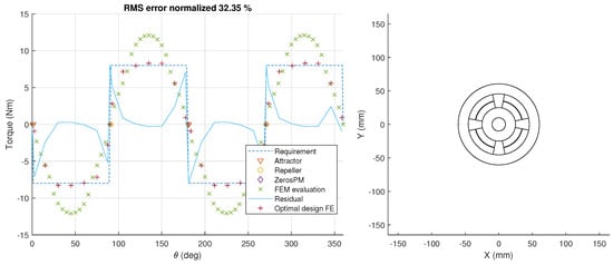
Figure 5.
Free shape approach using polynomial formulation, optimization results for rectangular reference torque. Left—FEM torque characteristic calculation, right—initial magnetic spring geometry.
Similar to the previous parametric optimization approach, the solutions in free shape optimization are not necessarily convex and it is not possible to extract the gradient of the solution to the geometry deformation, except numerically. Therefore, a blackbox optimization algorithm is used for optimization.
2.2.3. Free Shape Optimization
The same as in the previous section, herein we start from an initial, nominal geometry. However, in this case, the nominal geometry is deformed using a set of geometric operators—sequentially. In the literature, this approach is known as free shape optimization and there are numerous examples of it being used in commercial software packages for, for example, airfoil optimization [8]. The domains are described as a geometric shape polygon and do not possess a parametric geometry that defines the shape. This makes it rather easy to capture the optimal geometry with the possible design spaces. On the other hand, it is somewhat difficult to consider the manufacturability of the geometry and explicitly constrain the optimization to the typical motor design, that is, the overlap between stator and rotor, or outer mechanical constraints. This has led to many evaluations of geometries that are infeasible and a rather high cost of optimization given the higher number of degrees of freedom in the optimization problem. It is the opinion of the authors that such an approach with additional limitations, that is, only applying geometric transformations to selected boundaries could produce the same results as the spline based optimization approach mentioned in the previous section. However, enforcing constraints on transformed features is still less streamlined than the use of spline control points.
2.2.4. Regarding Topology Optimization
Finally, topology optimization with its increased number of degrees of freedom and the use of topological derivatives for somewhat improved convexity of the optimization could seem to be a likely method of choice. However, the step-in for performing topology optimization is rather high. It also has highest demands on the computational load, and requires open access to FEM software for calculation of topological derivative. It is difficult to exclude unfeasible non-manufacturable designs explicitly, therefore pre-calculation check, penalization of certain geometric feature is just a proxy to manufacturable designs. More specifically to the problem at hand (shape optimization of magnetic assemblies), the possibility to create new domains seems to be superfluous. The authors had a broader look at the literature for a review of the topic [9,10,11]. Even there it is difficult to find a topology optimization problem in applied electromagnetic (motor design, magnetic bearing design etc.) where topology optimization was successfully used for more than the shaping of pre-existing domains. Maybe one counter-example is the saturation bar shaping in IM-PMSM (internal magnet PMSM) such as the LM-PMSM (line start PMSM) example [12], where we clearly see that for some designs, the existing domains merge or completely disappear, resulting in topological innovation.
3. Results
In this section, we documented the application of above mentioned approaches on three already mentioned reference cases:
- crank-rocker at constant speed;
- conjugate cam-follower at constant speed;
- rectangular torque characteristic (academic use case).
3.1. Extended Parametric Optimization
Even though this approach is the least generic of the studied shaping optimization approaches, we had most success using it to deliver manufacturable designs and an acceptable performance of the magnetic spring with a reasonable design time and effort for each of the design problems.
Figure 6 presents the resulting torque characteristic and the geometry for crank rocker at constant speed.
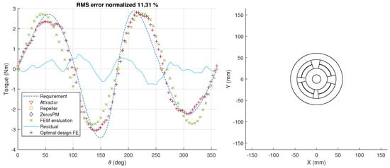
Figure 6.
Extended parametrization approach, optimization results for 4 bar linkage reference torque. Left—FEM torque characteristic calculation, right—initial magnetic spring geometry.
The initial guess based on attractors and repellers (visible in Figure 6 as green—initial ‘FEM evaluation’) is already qualitatively providing a good fit, indicating that the proposed initial design is topologically a good fit and that only shaping optimization is required from here on. Using the extended parametric approach allows for an additional improvement in the torque characteristic fit, but a considerable root mean square (RMS) error remains. This is due to the limitations in geometry shaping feasible within the extended parametric description of the magnetic spring and is considered to be a hard limit to the performance of this method.
Figure 7 leads to similar conclusions. However, here, the final design is significantly better and only a very small deviation from the peak torques are remaining in the optimized designs. Interesting to mention here is that the optimized magnetization used for this design is radial, as opposed to diametrical magnetization in the previous design.
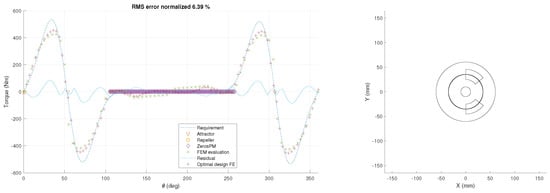
Figure 7.
Extended parametrization approach, optimization results for cam-follower reference torque. Left—FEM torque characteristic calculation, right—initial magnetic spring geometry.
The designs arising from extended parametric optimization are the first candidates for experimental validation; in particular the cam profile, given the relatively good fit for such a peculiar torque characteristic requirement.
For the rectangular case, the same magnetization is used. However, the results are not shown here as the optimizer had difficulties outperforming the initial guess significantly with respect to the shape fit. The only improvement found was in the amplitude of the torque (adjusted by magnetic spring length). The initial guess results are visible in the figures (Figure 5 and Figure 8) for the parametric shape optimization below.
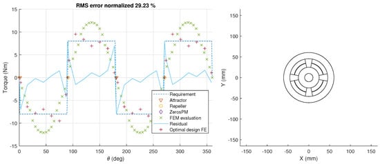
Figure 8.
Free shape approach with spline formulation, optimization results for rectangular reference torque. Left—FEM torque characteristic calculation, right—initial magnetic spring geometry.
The limitations of this problem formulation are clearly visible when trying to perfectly match the requirement in Figure 6. On the other hand, even though the requirement in Figure 7 shows a greater deviation from a single order sine profile, the approach is more successful at matching the requirement here with normalized RMS error of 6.39% as opposed to 11.31%, in former case.
3.2. Parametric Shape Optimization
For parametric shape optimization, an initial guess for the parameters of the polynomials and splines is made. The resulting geometry is imported in FEMM [4]. The torque characteristic of the magnetic spring is evaluated by stepwise rotating the rotor. After that, the FEA results are handled back to SyMSpace and compared to the reference torque characteristic. Using SyMSpace’s optimizer the parameters of the magnetic spring are varied, minimizing the given cost function.
In Figure 5 and Figure 9a the optimized geometry and resulting torque using polynomials for shape deformation are shown. The most significant deviations occur at the steep edges of the reference signal. The geometry in Figure 9b results from an optimization with a spline defined by five reference points which are equidistantly distributed over the magnet angle. The steep edges of the reference torque can be fitted better than with the polynomial approach, see Figure 8.
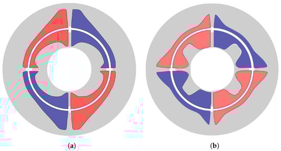
Figure 9.
Resulting geometry from parametric shape optimization for rectangular reference torque. (a) Polynomial parametrization. (b) Spline parametrization.
Since changing one coefficient of the deformation polynomial changes the shape along the whole contour it is nearly impossible for the optimizer to map the coefficients to the output. If, on the other hand, a spline point is changed, the magnet is only deformed locally. Therefore, the optimizer is able to find relationships between the spline points and the resulting cost function. However, both geometries can hardly be produced without resorting to advanced manufacturing methods.
As a next step, the torque characteristic of the conjugate cam-follower shown in Figure 10 is used as a reference torque.
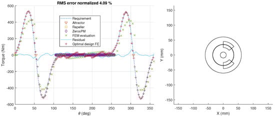
Figure 10.
Free shape approach with spline formulation, optimization results for conjugate cam-follower reference torque. Left—FEM torque characteristic calculation, right—initial magnetic spring geometry.
For the shape optimization, spline points are used because they showed better results than polynomials in the previous example. Figure 11a shows the resulting geometry after 22 h optimization on 40 parallel kernels.
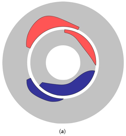
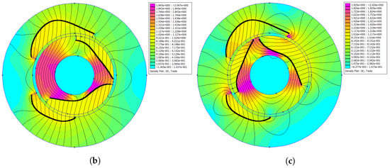
Figure 11.
Result of free shape optimization using spline formulation, for conjugate cam-follower reference torque profile. (a) Resulting design geometry. (b) magnetostatic simulation result for magnetic flux density in magnetic spring at . (c) magnetostatic simulation result for magnetic flux density in magnetic spring at .
The torque characteristic can be reproduced with very small deviations. This result also demonstrates the excellent capabilities of this spline based method in comparison with the extended parametric optimization. However, the manufacturability of such a geometry is most likely limited to only bonded magnet types, that is, leading to lower energy density or a requirement towards improved manufacturing methods. Therefore, the choice between results in Figure 7 and Figure 10 is to be made as a trade-off on system design, choosing between the impact of the torque characteristic fit vs. material cost and inertia of the magnetic spring.
4. Discussion and Outlook
Together with the methodological contribution, this article aimed to quantify the intrinsic benefits and limitations of each magnetic design shaping method and presents a benchmark on a real design problem performed for a magnetic spring design for textile machinery application [13]. Two approaches were developed and tested in model environment:
- extended parametric optimization—breaking design symmetry in conventional designs Section 2.2.1;
- domain boundary shaping using parametric spline approach Section 2.2.2.
Table 2 provides an overview of the resulting KPIs for application of these methods to the cam-follower case. As expected, the number of decision variables is lower in the former approach, needing less design evaluations to converge. However, the latter method leads to a significantly better fit of the requirement torque, even though the difference in normalized RMS error for cam-follower case is not as dramatic as on some of the other examples studied here. Observe that for black-box optimization the total number of evaluations can be much larger than the number of evaluations needed to converge to a min. feasible value for a specific parametrization. Due to the very low termination normalized RMS error, both approaches in this table are either terminated at maximum no. of iterations as set in the optimizer, or manually terminated by the user. Such a low min. error is specified to explore the design space as much as possible, providing at least a “brute force” computational guarantee of convergence, when other theoretical guarantees are not feasible for this sort of inverse problems.
Table 2.
Comparison of applied methods on cam-follower case for converged optimization solutions.
The second approach shows great potential for broader use and it could be used to efficiently address many shaping optimization problems in low frequency electromagnetic design, that were attempted in the literature with topology optimization:
- IPM back iron [12] harmonic field shaping for line start sync machines;
- magnet surface shaping in breadloaf magnets;
- generally for additive manufacturing (AM) for electrical motors.
It is our opinion that this could be a more versatile solution than parametric optimization of the shapes currently used by motor designers, that is, matching the performance of some more advanced approaches reviewed here, while keeping the complexity relatively low. As a follow-up it is of interest to streamline this approach in the currently used software tools. This would make this technique applicable to a wider range of problems and confirm our hypothesis.
The added value of the studied approaches for the free shaping of magnets studied in this article could be somewhat limited due to manufacturability due to the use of sintered anisotropic permanent magnets of NdFeB or SmCo type. Conventional manufacturing of such magnets relies on grinding for achieving complex shapes as in the outcome of the spline-based optimization. This increases manufacturing costs and material usage. Manufacturing techniques such as injection moulding would offer an elegant solution for achieving complex shapes without difficulties but are, in today’s industrial standard, limited to isotropic permanent magnets. These materials achieve only around 50% of the magnetic remanence flux densities and a fraction of the energy product of their anisotropic counterparts. This disadvantage could be overcome by new methods emerging in the field of additive manufacturing. A promising candidate could be metal injection moulding (MIM) for injection moulding of anisotropic permanent magnets [14,15], thus solving the shape challenge while not suffering from material limitations. Nevertheless, typical constraints for injection moulding and AM such as minimum feature size, maximum part size and geometry still persist, although significantly less prohibitive than the current state or practice. Furthermore, 3D-printing of permanent magnets, including an anisotropic alignment process [16], may additionally add flexibility to prototyping and small series applications. These manufacturing techniques represent net shape methods which makes them very resource-efficient since no scrap is produced and no material is lost through, for example, a grinding process. Additionally, these methods open up the possibility to use recycled permanent magnet materials [17]. With increasing material in the global product cycles, this topic will further gain importance in the future. Consequently, these manufacturing techniques have been and continue to be in the center of several EU-funded projects such as REProMag, SUSMAGPRO, or REE4EU.
The study was conducted as model based design exercise for several cases of magnetic spring design. At the present moment in time, only virtual designs have been developed for the industrial use cases, that is, for the highly asymmetric characteristic required for cam-follower motion in an industrial machine drivetrain in the range of 100 kW. It is of great interest for the authors to also build a physical prototype and validate the presented model based results, especially for the peculiar cam-follower use case. As discussed above, today’s manufacturing possibilities may still present limitations; however, the results presented here for the first time provide a clear idea of the potential for the shaping of magnetic spring characteristics for several appropriate industrial cases.
Topology optimization and free shape optimization were studied briefly but abandoned due to the mismatch with goals of this methodology. Although these methods offer a broader range of possible geometries, the downsides outweighed the benefits. First of all, the manufacturability of designs is a difficult problem to deal with, and second, the need for new domains (topological change) is limited in our case and can easily be captured by a smart initial guess. The remainder of the problem can be dealt with using only parametric shape optimization techniques in one of the forms presented above.
Regarding the optimization algorithms, we observed limitations on the maximum number of parameters for blackbox optimizers at approximately . A potential solution is to use multi-objective optimization to tackle this problem for or as presented above to break the optimization problem into several sequences where: (i) general sizing and limited shaping is performed using approach in Section 2.2.1; and (ii) specific domain boundary shaping is performed using spline based shaping in Section 2.2.2.
5. Conclusions
In this article, two shaping optimization approaches for electromagnetic optimization were developed and tested in model environment, specifically on magnetic spring characteristic shaping problem set:
- extended parametric optimization—breaking design symmetry in conventional designs Section 2.2.1;
- domain boundary shaping using parametric spline approach Section 2.2.2.
The second approach shows great potential for generic use and it could be used to efficiently address many shaping optimization problems in low frequency electromagnetic design that can be found in literature attempted with topology optimization. It is our opinion that it could be a more versatile solution than parametric optimization of the shapes currently used by motor designers, that is, matching the performance of some more advanced approaches reviewed here, while keeping the complexity relatively low. As a follow-up it is of interest to streamline this approach in the currently used software tools. This would make this technique applicable to a wider range of problems and confirm our hypothesis.
Future work should extend the existing methodology by using metrics for manufacturability that include several mentioned methods: bonded isotropic magnets, 3D printed anisotropic, MIM magnets and conventional sintered magnets.
Author Contributions
Conceptualization, B.M. and H.M.; methodology, B.W. and B.M.; software, B.W. and B.M.; investigation, B.W. and B.M.; writing—original draft preparation, B.M.; writing—review and editing, B.M., B.W. and H.M.; visualization, B.W. and B.M.; supervision, H.M. and B.M.; funding acquisition, H.M. All authors have read and agreed to the published version of the manuscript.
Funding
This work has been partly carried out within the framework of Flanders Make’s ICON project “Torque Ripple Reduction” funded by the agency Flanders Innovation & Entrepreneurship (VLAIO). Flanders Make is the Flemish strategic research centre for the manufacturing industry. This work has been supported by the COMET-K2 Center of the Linz Center of Mechatronics (LCM) funded by the Austrian federal government and the federal state of Upper Austria.
Data Availability Statement
The data presented in this study are available on request from the corresponding author. The data are not publicly available due to large size of the optimization dataset.
Conflicts of Interest
The authors declare no conflict of interest. The funders had no role in the design of the study; in the collection, analyses, or interpretation of data; in the writing of the manuscript, or in the decision to publish the results.
References
- Mrak, B. Magnetic Springs for Improved Performance of Highly Dynamic Drivetrains. Ph.D. Thesis, KU Leuven, Leuven, Belgium, 2020. [Google Scholar]
- Mrak, B.; Lenaerts, B.; Driesen, W.; Desmet, W. Optimal Magnetic Spring for Compliant Actuation—Validated Torque Density Benchmark. Actuators 2019, 8, 18. [Google Scholar] [CrossRef] [Green Version]
- Mrak, B.; Adduci, R.; Weckx, S.; Driesen, W.; Desmet, W. Novel phase-bound magnetic vibration absorber for improved NVH performance of a wind turbine gearbox. In Proceedings of the ISMA 2018—International Conference on Noise and Vibration Engineering and USD 2018—International Conference on Uncertainty in Structural Dynamics, Leuven, Belgium, 17–19 September 2018; pp. 4833–4845. [Google Scholar]
- Meeker, D. FEMM-4.2–Finite Element Method Magnetics. Available online: https://www.femm.info/wiki/HomePage (accessed on 21 April 2019).
- Silber, S.; Koppelstätter, W.; Weidenholzer, G.; Segon, G.; Bramerdorfer, G. Reducing Development Time of Electric Machines with SyMSpace. In Proceedings of the 2018 8th International Electric Drives Production Conference (EDPC), Schweinfurt, Germany, 4–5 December 2018; pp. 1–5. [Google Scholar]
- Joris, G.; Edward, K. Symbolic Equation Extraction from SimScape. In Proceedings of the Benelux Meeting on Systems and Control, Soesterberg, The Netherlands, 27–29 March 2018. [Google Scholar]
- Le Digabel, S. NOMAD: Nonlinear optimization with the MADS algorithm. ACM Trans. Math. Softw. 2011, 37, 44. [Google Scholar] [CrossRef]
- Le, C.; Bruns, T.; Tortorelli, D. A gradient-based, parameter-free approach to shape optimization. Comput. Methods Appl. Mech. Eng. 2011, 200, 985–996. [Google Scholar] [CrossRef]
- Erin, K.; François, H.; Pierre, D.; Christophe, G. Combination of topology optimization and Lie derivative-based shape optimization for electro-mechanical design. Struct. Multidiscip. Optim. 2019, 59, 1723–1731. [Google Scholar] [CrossRef]
- Labbé, T. Topology Optimization Methods for the Design of Electromagnetic Actuators. Ph.D. Thesis, Université catholique de Louvain- Ecole Polytechnique de Louvain, Ottignies-Louvain-la-Neuve, Belgium, 2011. [Google Scholar]
- Gangl, P.; Amstutz, S. Toplogical derivative for nonlinear magnetostatic problem. Electron. Trans. Numer. Anal. 2019, 51, 169–218. [Google Scholar]
- Jan, B.; Ladislav, K.; Gerd, B.; Iveta, L.; Siegfried, S.; Ondrej, V. Topology Optimization of Rotor Bars Geometry and Arrangement for a Line-Start Permanent Magnet Synchronous Machine. IEEE Access 2021, 9, 115192–115204. [Google Scholar] [CrossRef]
- Mrak, B.; Willems, J.; Baake, J.; Ganseman, C. Co-Design of Novel Adaptive Magnetic Springs for Reliable Industrial Variable Stiffness Actuation. ASME/IEEE Trans. Mechatron. 2021; under review. [Google Scholar]
- MIMplus Technologies: How innovation and research is driving developments in NdFeB magnets and sinter-based AM. PIM Int. 2021, 15, 75–82.
- Hartwig, T.; Lopes, L.; Wendhausen, P.; Ünal, N. Metal Injection Molding (MIM) of NdFeB Magnets; EDP Sciences: Les Ulis, Essonne, France, July 2014. [Google Scholar] [CrossRef] [Green Version]
- Klaus, S.; Christian, H.; Iulian, T.; Spomenka, K.; Boris, S.; Daniel, K.; Michael, R.; Christian, L.; Martin, G.; Dieter, S. 3D printing of polymer-bonded anisotropic magnets in an external magnetic field and by a modified production process. Appl. Phys. Lett. 2020, 116, 092403. [Google Scholar]
- Khazdozian, H.A.; Manzano, J.S.; Gandha, K.; Slowing, I.I.; Nlebedim, I.C. Recycled Sm-Co bonded magnet filaments for 3D printing of magnets. AIP Adv. 2018, 8, 056722. [Google Scholar] [CrossRef] [Green Version]
Publisher’s Note: MDPI stays neutral with regard to jurisdictional claims in published maps and institutional affiliations. |
© 2022 by the authors. Licensee MDPI, Basel, Switzerland. This article is an open access article distributed under the terms and conditions of the Creative Commons Attribution (CC BY) license (https://creativecommons.org/licenses/by/4.0/).