1. Introduction
Cable-driven parallel robots (CDPR) use a set of cables that are coiled on digitally controlled winches to move a payload, such as a platform. CDPRs can be designed very light-weight, which makes them fast and efficient. Moreover, they can cover large workspaces in comparison to serial manipulators, as the cables can span over huge distances [
1]. The range of applications for CDPRs investigated is increasing, including, e.g., intralogistics [
2] or automation in construction [
3]. Further applications are, e.g., vertical green maintenance [
4] or lamella cleaning in sedimentation tanks [
5]. Additionally, research has been conducted to improve the performance of CDPRs in underwater operations [
6]. In [
7], the accuracy, repeatability and long-term running of a CDPR is investigated. A recent project in which the authors are involved is a CDPR for automated masonry construction [
8]. This implies a rapid progression of the future industrial utilization of CDPRs.
Consequently, aiming at practical applications, industrial safety requirements must be met in the future to avoid damage to the robot and its environment. Even if there are commonly known rules and guidelines for fundamental components, such as pulleys and cables, a cable might still fail [
9]. Within literature, the detection of failures and their outcome in CDPRs has been broadly discussed. Several methods have been presented to handle such situations. In [
10], initial thoughts on potential errors and error tolerance in CDPRs were provided, and the consequences of a failed cable on the nullspace of the robot’s Jacobian were examined. The impact of a failed or slack cable resulting in improper cable forces is considered in [
11]. It aims to recover the force and momentum capacity of the robot’s platform. The conditions of practicability for this purpose are suggested. In [
12], a strategy for recovery after a cable failure, where the end effector can be outside of its workspace, is proposed. It is based on the planning of an elliptical path within a dynamic trajectory. In [
13], the workspace of a predefined system after cable failure is investigated. Moreover, an algorithm for the planning of a feasible trajectory along a straight line path back into the workspace is introduced. This work was extended in [
14] by including drivetrain models. In [
15], the approach was implemented on a prototype with three degrees-of-freedom (DOF) of the mobile end effector and four cables.
In [
16], algorithms to stop a cable-driven camera system after a cable failure are proposed. Dynamic trajectories into the post-failure workspace are planned. Collision avoidance is considered and preferred target positions are identified. In [
17], the effects of cable anchor point alignment on post-failure behavior is studied for an underwater CDPR. The winches are installed on marine barges and their optimal positions are determined to increase the systems fault tolerance. In [
18], safety concepts for CDPRs are presented. This features, e.g., approaches to shorten the stopping distance during emergency braking and the monitoring of the workspace.
The strategies after cable failure described so far mainly focus on trajectory planning back into the remaining workspace, or cable force redistribution when the platform remains in the workspace after failure. On the contrary, the authors of this work have proposed two strategies to guard the platform back into the post-failure workspace without a predefined trajectory [
9]. One strategy presented is based on potential fields employment, whereas the other aims to minimize the systems’ kinetic energy [
9].
In more recent works, the authors also proposed including actuated moving pulleys in cable failure strategies. The strategy of minimizing the systems’ kinetic energy is enhanced and simulated using ideal assumptions in [
19].
However, the proposed methods of the authors have neither been validated in loop-closure of a control algorithm, nor been tested in detailed multi-body simulations. Moreover, the presumed failure of a control algorithm commonly used by the authors was not demonstrated before. The aim of this contribution is to close this gap. Following a strictly model-based testing scheme, the examined behavior of the introduced emergency strategy is analyzed, discussed and compared to the commonly used control algorithm. This paves the way for future experimental validation on a prototype.
The structure of the paper is given in the following: An introduction on CDPRs is given first, focusing especially on cable failure and methods to cope with this issue.
Section 2 introduces the kinematic and dynamic robot models, as well as the cable and drivetrain model applied within this work. In
Section 3, an emergency strategy aiming to minimize the system’s kinetic energy is introduced. This strategy involves nonlinear model predictive control. The dynamic multi-body simulation environment based on the modeling fundamentals used within this work is shown in
Section 4, and also includes a standard position controller. For the chosen set of robot parameters, a brief examination of the post-failure static equilibrium workspace is carried out in
Section 5. Subsequently, dynamic simulations within the chosen environment are performed, comparing the standard controller approach and the presented emergency controller within a cable failure scenario. This analysis is extended regarding the computation time and real-time suitability of the emergency algorithm, considering an emergency controller restricted in iterations. Finally, a summary and outlook on future work towards implementation within real hardware are given.
3. Emergency Strategy Based on Energy Minimization
Cable failure during the operation of CDPRs can lead to severe outcomes. As the end effector might move in an uncontrolled manner, collisions can occur, possibly leading to substantial damage to the machine, employees or the surroundings. Moreover, the carried payload might be lost. Consequently, the necessity for action strategies after a cable failure is given, especially during the transfer of this technology into industry. When a cable fails, the end effector can suddenly get beyond the borders of its pre-failure workspace. If this is the case, standard methods for cable force calculation are expected to fail [
9]. Two strategies of action after a failure have been proposed by the authors in previous work [
9]. One of those is presented in particular as follows.
For simplicity, it is assumed now that just one cable fails. Hence, a CDPR with a number of cables remains. In the rest of the paper, the force distribution of the remaining cables is referred to as . Accordingly, the corresponding structure matrix, reduced by the column of the broken cable, is . As long as at least a single cable remains after a cable break, the movement of the end effector can still be influenced. In case of CDPR with higher redundancies r, there might even be a good chance to stop the movement in a controlled way, even after the loss of multiple cables. However, the post-failure workspace can be significantly smaller than the original one. This promotes an unfavorable scenario where the platform suddenly gets beyond the borders of its pre-failure workspace, as mentioned above.
A possible approach to safeguard the end effector in a controlled way is to incorporate model predictive control [
23] in order to minimize the systems’ kinetic energy after a cable break [
9]. Within this strategy, the state of the system is predicted utilizing the dynamical and nonlinear model of the robot to compute cable force distributions, minimizing the end effector’s kinetic energy over time. Consequently, this minimizes the system’s velocity, which leads to a system stop. Hence, if the system is finally able to stop, the robot will automatically have been led into the remaining post-failure workspace. This strategy does not require the definition of a goal pose, which is highly advantageous. A rigid body is assumed in order to model the moving masses of platform and payload. Its kinetic energy is defined as
The angular velocity
of the body is directly dependent on
[
21]. Therefore, the magnitude of
needs to be be minimized in order to decrease the system’s kinetic energy. The system is described by the nonlinear discrete state equations
It is based upon the nonlinear system function
derived from Equation (
5).
is the state vector containing position and velocity.
describes the output of the system. Both are defined as
Applying the
identity matrix
, matrix
describes the output:
The system’s input vector contains the remaining cable forces
The state vector
for the next time step is obtained from
applying numerical integration with a fixed prediction step size
. For this purpose, the Euler–Cromer scheme is used:
Now, a cost function
J is set up as follows:
Herein, the number of steps
is the prediction horizon, whereas
is the control horizon. To obtain set-point cable force distributions
, Equation (
18) is minimized in each time step, considering the given limitations for cable forces. In order to stop the system, the goal velocity is set to
. As soon as the platform gets to a full stop and the cable force distribution remains steady, the costs
J will be minimal. The weighting parameters
and
can be used to scale the optimization problem.
5. Dynamic Simulation—Experiments and Results
Within this work, a planar dynamic CDPR model using two translational DOF and four cables (
,
) is considered. In comparison to former work of the authors featuring models with two DOF (see, e.g., [
9]), this model is extended by drivetrain modeling and basic cable modeling, as well as a standard control system model (see
Section 2 and
Section 4). Note, that for the model at hand, the rotational components are set to zero in Equations (
5) and (
17). For simplicity, all elements of parameters and variables that go beyond the chosen two DOF are not displayed in the following.
The model is subject to gravity in the negative
y-direction. The cables are massless but can become slack (see
Section 2.3). Modeling of pulleys is neglected for simplicity, as well as collisions between cables or disturbances. The chosen set of parameters for the simulation model is as follows. The cable and drivetrain parameters are inspired by the SEGESTA prototype.
Note, that only results for the failure of an cable coming from above are introduced in this work, due to lack of space.
5.1. Analysis of the Post-Failure Workspace
As demonstrated in the former work of the authors [
9,
19], the workspace of a CDPR can change significantly after a cable failure. This increases the risk of the platform being outside the workspace for static force equilibrium (
) post-failure, leading to an inevitable movement of the platform.
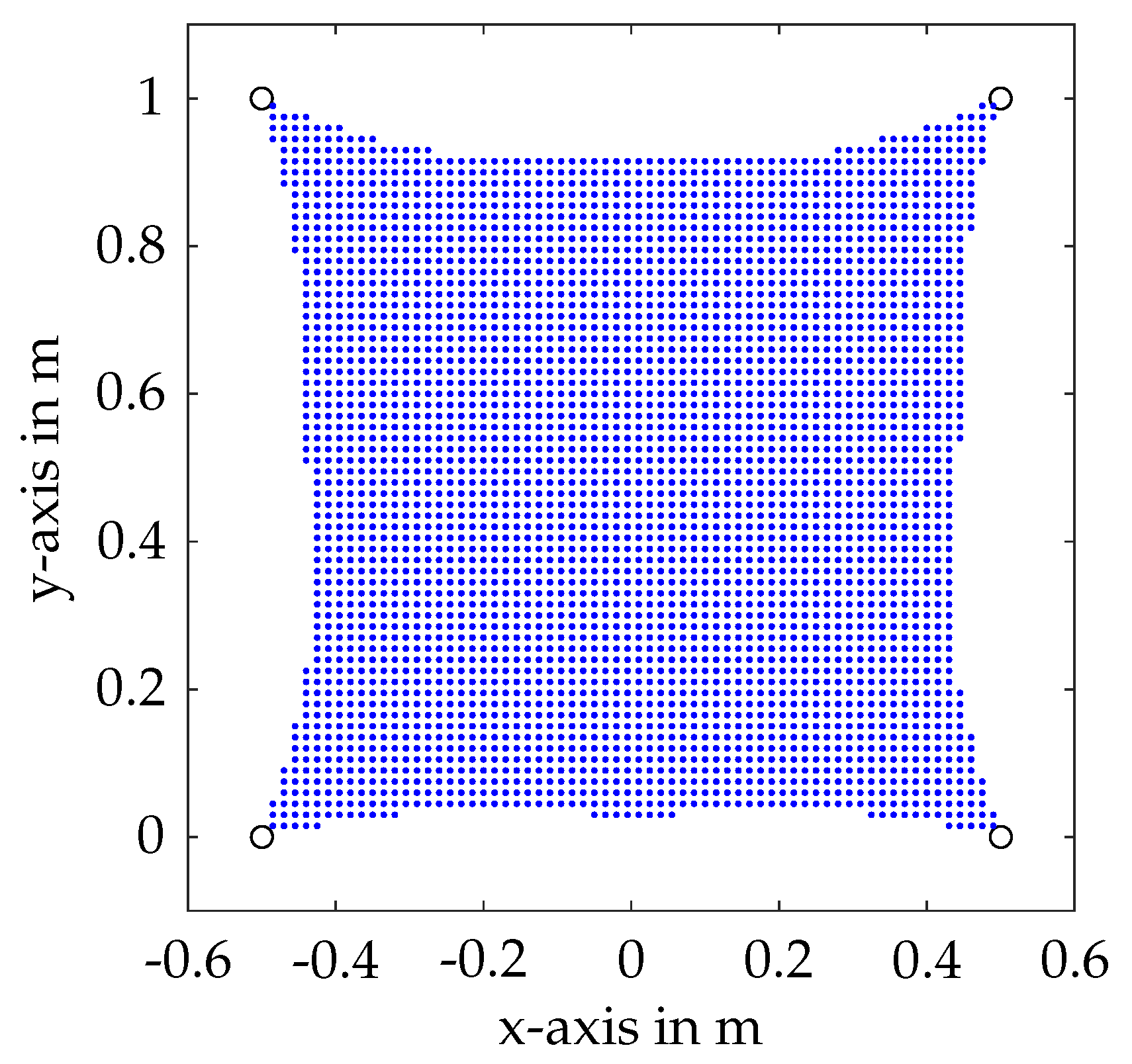
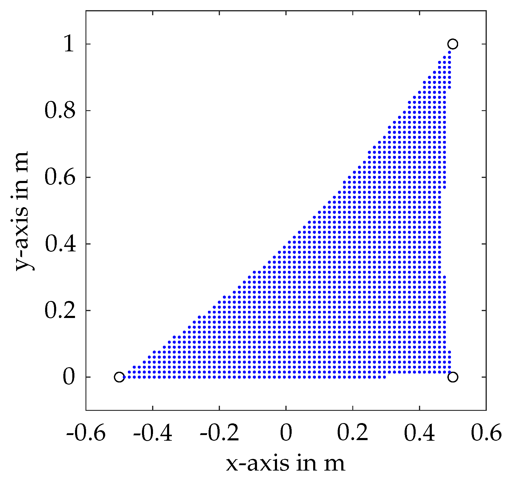
For the model parameters at hand, the
for static equilibrium pre- and post-failure under influence of gravity is displayed in
Figure 4 and
Figure 5. The workspace was calculated using a discrete point grid and checking for a feasible cable force distribution at each point while applying the closed-form method [
1]. Clearly, it is visible that the workspace is approximately halved post-failure for the given model, promoting the risk of the platform being outside the workspace after cable failure.
5.2. Multi-Body Cable Failure Simulation with Standard Controller
To perform dynamic cable failure simulations, the intervention points of the cable failure within the model need to be defined. At a given time, the cable failure is induced by setting the output force of the cable model to zero for the broken cable. Therefore, only the remaining cables can impose a dynamic effect on the robot platform within the robot model; see
Section 4.1. Moreover, due to the missing reactive force from this cable, the associated drivetrain can easily accelerate the winch only bounded by friction. However, the winch movement does not impose any effect on the cable model anymore. Still, due to the feedback of motor angles and velocities, the controller senses the winch movement.
For a first experiment, the platform is set into a position at
, while the APD controller aims to hold that position as goal pose. Desired velocity and acceleration are set to zero. Note, that this position is outside of the
after cable failure. The parameter are set to
and
. To generate a desired cable force distribution from the controller output (see
Section 4.2), the closed-form method is used [
1]. Subsequently, the model behavior after cable break is investigated, as if the controller would have no inherent emergency strategy and no detection of the cable failure. The cable failure is induced at
s.
Figure 6 shows the trajectory of the platform and the drives after cable failure employing the augmented PD controller without emergency strategy. As the APD controller has no knowledge of the cable failure, it tries to hold the old desired position, leading to an undesired movement of the platform. The velocity in the
x-direction reaches
, and reaches
in the
y-direction. The drives coil the cables in an undesired manner, trying to maintain the desired cable force given from the augmented PD controller. The drive velocities reach up to
when the platform is falling down. When the cables get back in tension, as shown in the right side of
Figure 7, the conducted impulses in cable forces can also be seen within the drive velocities. They are caused whenever the slack cables catch the falling platform. After being pulled into the reduced
with the remaining cables and some uncontrolled movement at the workspace border, the joint errors exceed a certain level, resulting in non-feasible cable force distributions (see
Figure 7, left). As displayed on the right side of
Figure 7, the remaining cables stay in tension after failure of the cable force calculation at approximately
s due to inertia and friction in the drivetrains and the mass of the falling platform, which finally crashes to the ground. This underlines the necessity for an emergency strategy, guiding the end effector back into the static equilibrium workspace in a controlled manner, where it can be stopped in a statically stable position without collision with the ground.
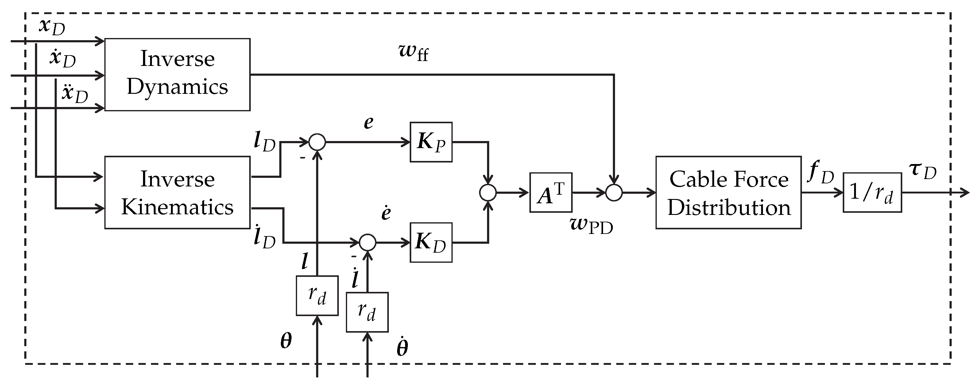
5.3. Implementation of the Emergency Strategy
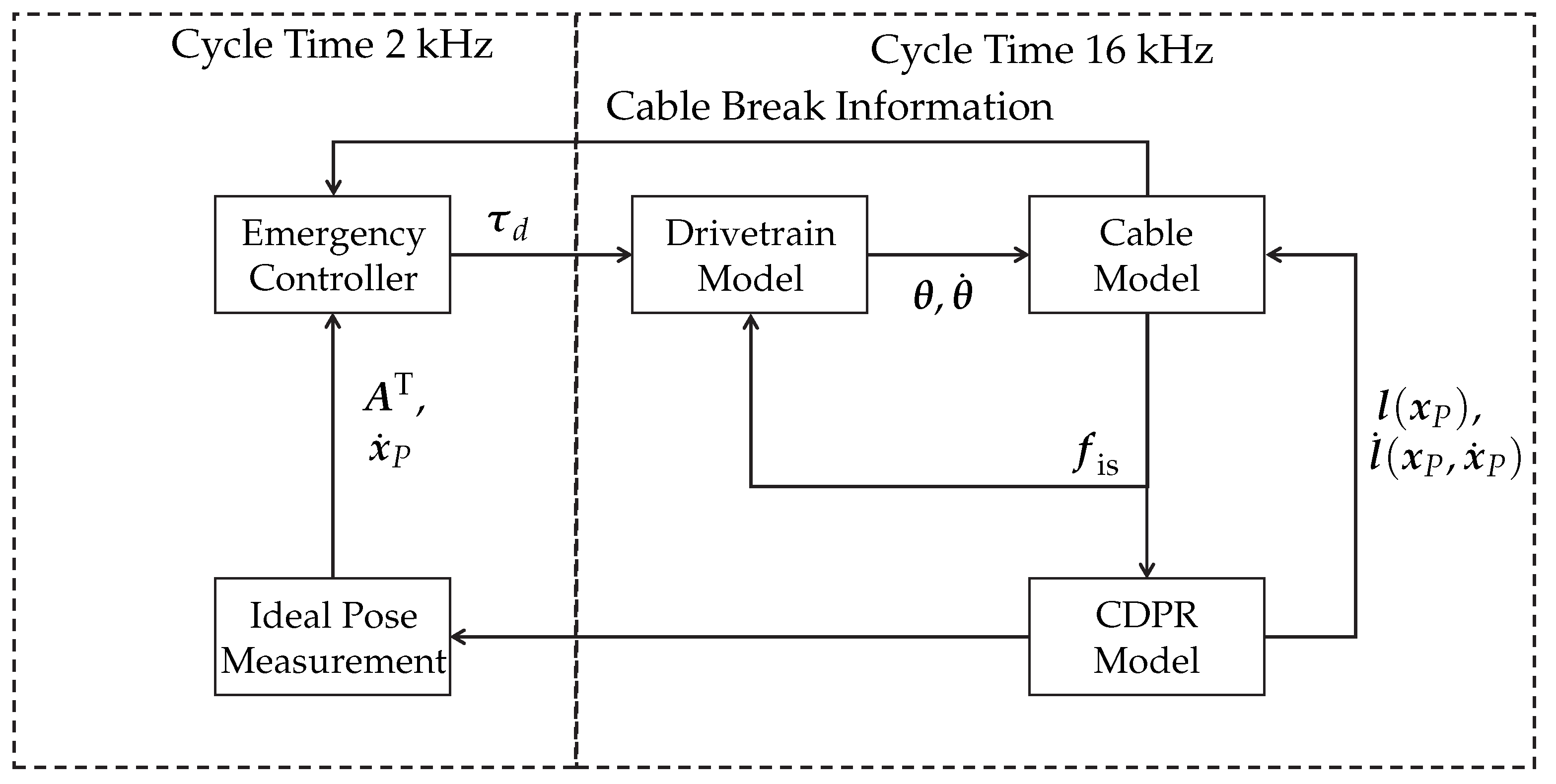
To implement the proposed emergency strategy (see
Section 3), a few changes are applied to the system structure, as displayed in
Figure 8. As soon as the cable fails, the information about the failure is directly fed to the controller for simplicity. At that point, the APD controller gets bypassed and the desired force from the last calculation cycle serves as a warm start point for the optimization-based emergency controller. Of course, for the application on real hardware, the cable failure needs to be detected. Potential points of detection that need to be investigated in future work are, e.g., cable force measurement or an unexpected deviation of the winch angle measurement. As the emergency strategy of kinetic energy minimization needs to have knowledge on the CDPR system state, an ideal pose measurement is assumed in the simulation. On real hardware, this task needs to be accomplished in real time by a suitable measurement unit, e.g., based on laser tracking. A second option would be the use of a forward kinematic algorithm. As a result of the risk of slack cables and uncertain movement of the end effector, implementing a cable failure resistant forward kinematic is nontrivial and part of future work.
After an induced cable break, the emergency controller will start to calculate desired cable forces while minimizing the cost function Equation (
18). The forces are converted to torques and commanded to the drivetrain system. Note that the NMPC algorithm is capable of predicting the system behavior over several time steps and, moreover, can obtain a more complex model, including, e.g., drivetrain behavior and friction. Due to the expected shortage in the available computation time when using the algorithm on prototype hardware later on, a rather simple model based on Equation (
17) is included in this work, and the prediction is carried out only over one time step, i.e.,
. The optimization problem is solved using MATLAB’s
fmincon() and an interior point algorithm. The output of the last cycle is fed back in order to enable a warm start of the optimization.
5.4. Multi-Body Cable Break Simulation with Emergency Strategy
The simulation is started with the same initial conditions as the experiment in
Section 5.2. Subsequently, as soon as the cable breaks, the APD controller is bypassed and the NMPC-based emergency controller starts. The NMPC parameters are set as follows:
=
,
,
ms,
.
fmincon() is used with default parameters first. Note that
is designed for less desired vertical movement, since it produces five times more costs in Equation (
18) than horizontal movements.
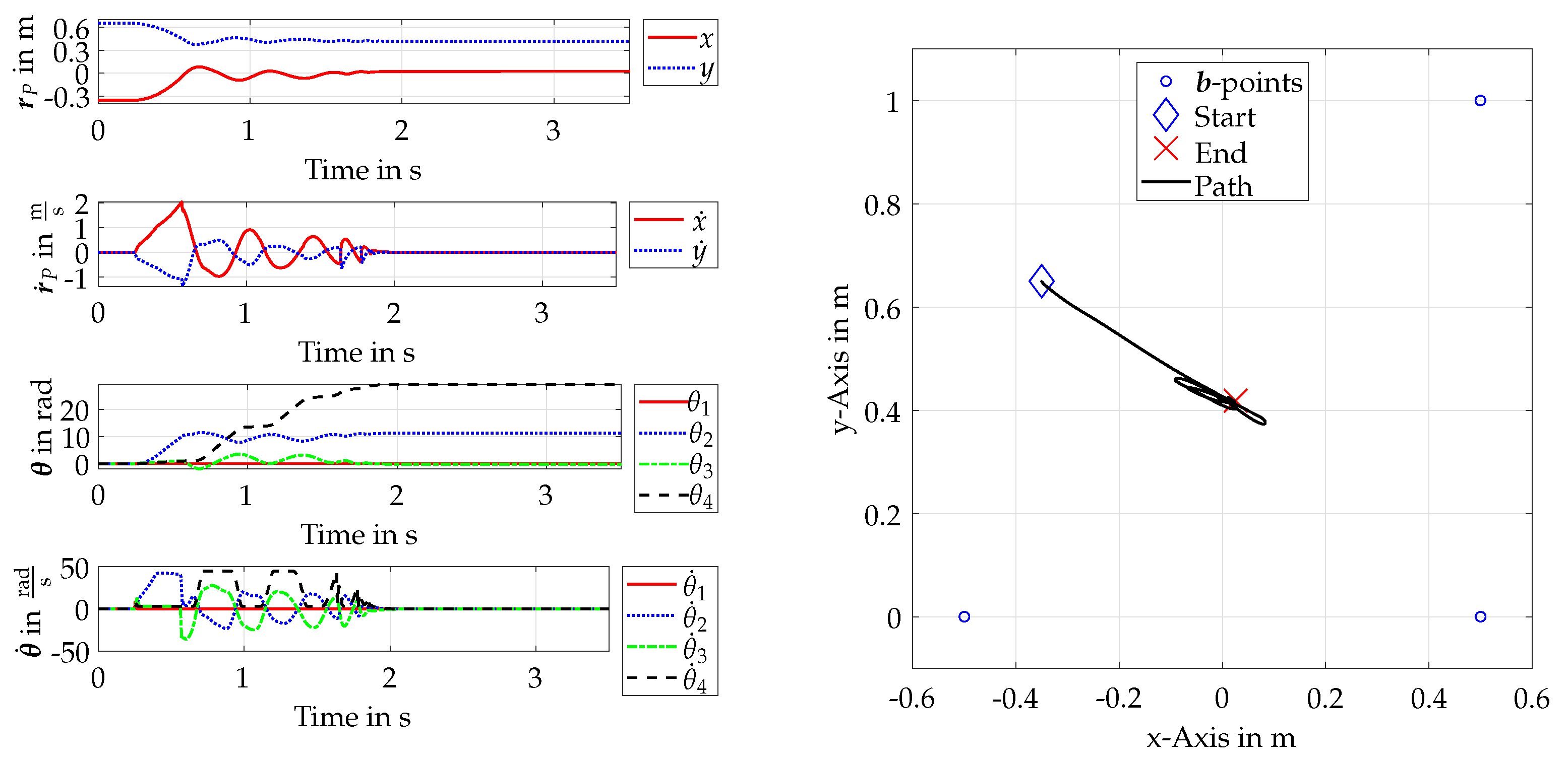
Figure 9 displays the trajectory of the end effector and the drives after cable failure while the emergency controller is commanding desired cable forces. It is worth noting that the platform travels a slight diagonal path into the remaining
, covering double the distance in the horizontal direction than in the vertical direction. In contrast to
Figure 6, the velocity in the
x-direction is slightly higher, whereas it is nearly halved in the
y-direction. This evidences that the chosen parameter
indeed leads to less vertical movement. The progressions of
and
show how the drives react properly to the commanded torque coming from the emergency method. The drives reach velocities up to
. Drive 1, which corresponds to the broken cable, stops movement, as there is no torque commanded to it. The platform can be dragged into the remaining workspace. Then, it is orbiting near the position where it entered the workspace. Finally, and in contrast to the experiment in
Section 5.2, it gets stopped without being subjected to collision with the robot boundaries.
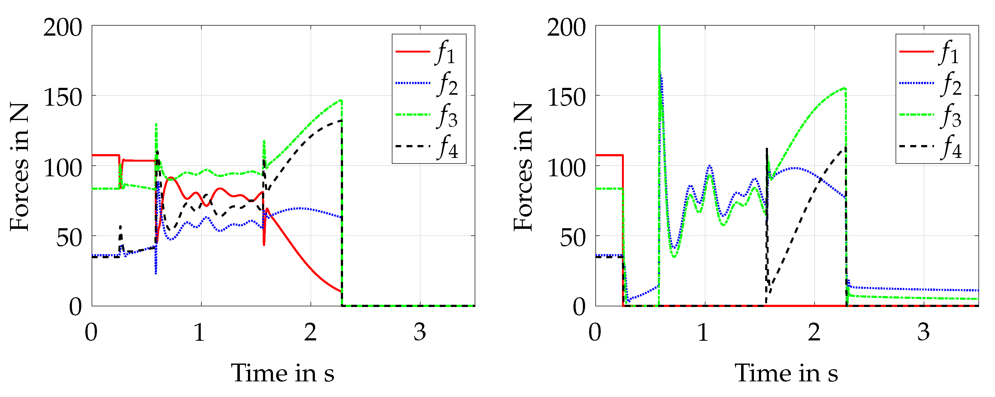
The commanded and measured forces in this experiment are shown in
Figure 10. The platform can be stopped in a statically stable position after approx. 2 s. The algorithm fully takes advantage of the given cable force boundaries, but does not exceed it within the commanded values. However, as displayed in the right hand figure, the current cable forces progress differently to the set forces throughout the trajectory. Since the cable force is not controlled directly, this is not unexpected. In the first segment after the cable failure, only cable 2 is held in tension while the platform starts to move. Since vertical movement is not desired within the optimization, cables 3 and 4 are commanded to minimum tension, which causes them to go slack in the model. Roughly
s after the failure, the platform reaches a pose where cable 3 gets back in tension, creating an impulse that slightly exceeds the desired cable force boundaries by 20 N. From there on, the platform starts to swing near the workspace border until cable 4 is brought back into tension by the algorithm. In that phase, the platform movement causes this cable to go in and out of tension a few times, creating some impulses in cable force 4. Notably, the second impulse also exceeds the cable force boundaries by 50 N. After all three cables are back in tension, the movement is stopped immediately. Even though the observed impulses exceed the desired cable force limits, which can be problematic on real hardware, the cable forces that occur are still far below the cable breaking force
. In summary, the experiment gives evidence that the chosen emergency method successfully works in a multi-body simulation environment and can stop the platform without collision in a fast manner.
5.5. Investigation on Computational Efficiency
Since the solution of numerical optimization problems on real-time hardware might lead to problems because of their iterative structure, a consideration of the computation time of the algorithm is crucial. The experiment from the last section is now evaluated in computation time and compared to an experiment with more restriction on the maximum allowed iterations of the optimizer. The calculations were carried out within Matlab R2019a using an Intel CPU i7-8700 with 3.2 GHz on a Windows 10 System. The maximum allowed iterations are now reduced from 1000 (default) to 10. Limiting the number of iterations within the optimizer may lead to a premature abortion of the optimization before reaching a cost function minimum. This impacts the cyclic computation time in a positive manner in terms of predictability and constancy. Nonetheless, the quality of the optimization result is expected to be negatively affected by this limitation.
In comparison to
Section 5.4, the trajectory of the platform and the drives after cable failure is quite similar, as displayed in
Figure 11.
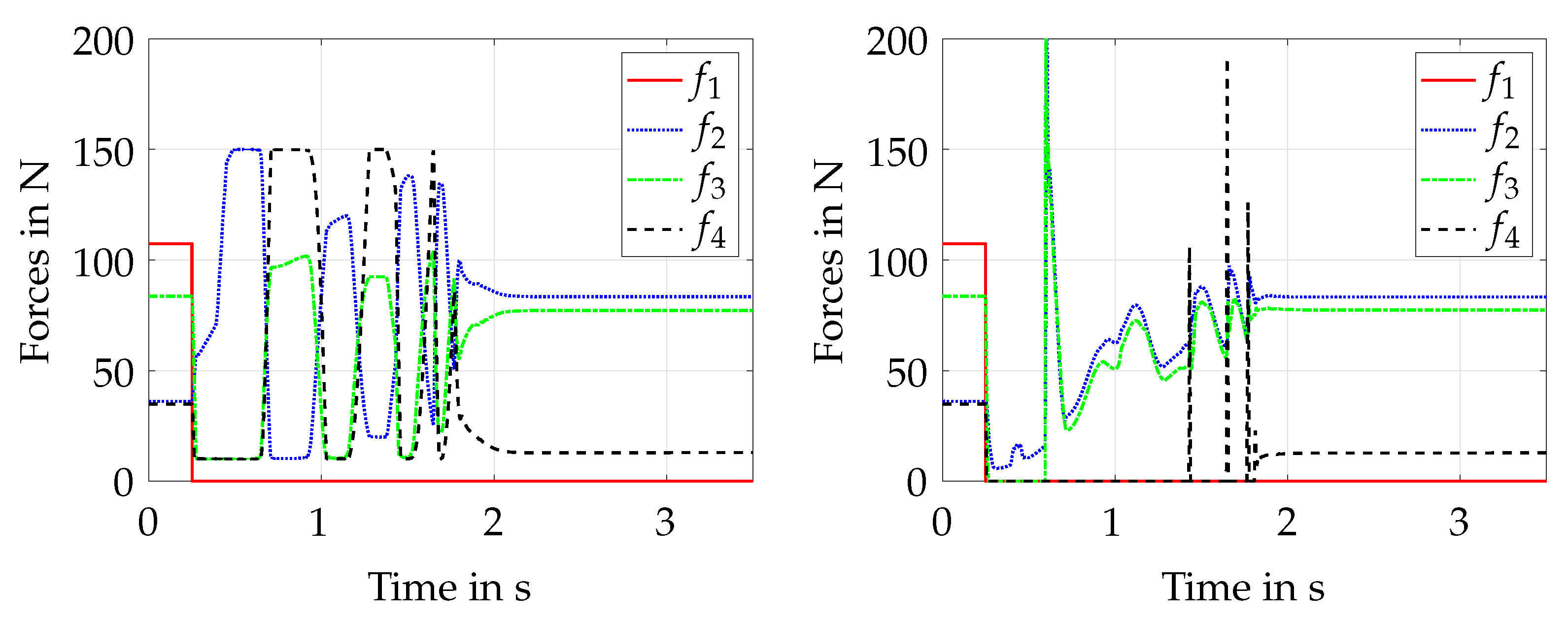
In addition, the progression of the cable forces, as displayed in
Figure 12, is comparable; however, some differences can be highlighted. The progression of the controlled forces is slower when a different extreme cable force distribution near the force boundaries is found. This can be explained by the assumption that the algorithm tends to stay in local minima or runs into the iteration restriction while propagating to a new optimal solution. This is also displayed by
and
. It is worth noting that the drives tend to react slower due to the commanded torque values. Drive 2, for example, is not accelerated as fast as in
Figure 9, while the first impulse in cable force 3 results in a higher negative velocity on drive 3. The platform is led to a full stop after
s, which is a little slower than with default parameters. Within the measured forces, it can be observed that the first impulse—when cable 3 gets back into tension—is roughly 30 N higher in comparison. In addition, the first impulse on cable 4 is 80 N higher, whereas the second impulse is 10 N lower. All in all, the height of the impulses when the slack cables go back into tension tends to rise.
The computation time per cycle step of the optimization algorithm throughout both experiments is displayed in
Figure 13. The mean times have been determined starting from
s, where the cable failure is induced and the optimizer is switched on. For default optimization parameters, the cycle times range from
ms to 25 ms while the platform is in motion, with a mean time of
ms. After the stop of the platform, the cycle times drop to a quite continuous level of
ms. The total mean computation time per cycle is
ms. As expected, restricting the maximum allowed iterations leads to more constant cycle times, as displayed on the right side of
Figure 13. Here, the cycle times range from
ms to
ms while the platform is in motion. The mean is
ms, which is approximately 1 ms lower than with default parameters. After stopping, the times drop to roughly
ms, leading to a total mean of
ms. Note that both cases have a peak in cycle time within the first iteration of the optimizer at
s due to initialization and memory preallocation. Restricting the algorithm further to 5 iterations maximum, the range of calculation times drops to 5 ms minimum and
ms maximum. However, in that case, the platform cannot be fully stopped within the simulation time, and the peak force that is induced when one cable get back into tension first is 260 N. The minimum number of iterations to stop the platform successfully in the present simulation example is 6. Still, in that case, a peak tension of 250 N occurs. Due to a lack of space, those experiments are not displayed here. This indicates that further restrictions of the maximum iterations are not useful. In summary, a compromise between the quality of the optimization result and computation time needs to be found when restricting the maximum iterations of the algorithm.
The experiments show that the maximum iterations can be reduced, which leads to a lower mean computation time, while maintaining comparable results. Even though the results look promising, the resulting computation times are still far away from the
ms time frame available in the hardware controller running at 2 kHz. To apply the algorithms on real hardware, this issue needs to be solved in future work. Moreover, as cables tend to become slack within the simulation, an additional position control or force control in joint space might be needed for experiments on hardware. As mentioned in
Section 5.3, the NMPC has a rather simple model of the robot. In future work, it might be reasonable to investigate the behavior of an extended algorithm through also incorporating winch dynamics and cable behavior. This will be especially interesting when carrying out tests on real hardware in terms of the quality of the results versus computation costs. Moreover, it needs to be investigated if a larger prediction horizon of the NMPC algorithm leads to better results in terms of experienced cable forces, cable slackness and platform movement. Finally, it is worth noting that the path of the platform and force progressions can be adjusted with the weighting parameters of the cost function—e.g., for less desired vertical movement or slower progression in the cable forces—which is not further investigated here.
6. Conclusions and Outlook
In this work, an emergency strategy after the cable failure of a CDPR based on kinetic energy minimization was presented and implemented within a multi-body simulation environment with control loop closure. The proposed simulation environment was briefly described, and also featuring modeling of the drivetrains, as well as a simple cable model. The chosen two DOF robot was analyzed regarding a pre- and post-cable failure static equilibrium workspace. A well-known position control approach was described and implemented within the simulation environment as a standard controller. To display the event of a cable failure, the dynamic simulation was modified accordingly. Within the simulation, the standard control approach was proven to fail. In contrast, utilizing the proposed emergency strategy, the platform was successfully recovered and stopped within the post-failure workspace. This paves the way for the application of the proposed method on robot hardware. However, some issues have been identified and discussed that need to be resolved in order to carry out hardware experiments. This includes, e.g., the reliable detection of cable failure and a real-time position determination in the emergency situation. For the latter, in order to close the control loop, a measurement unit or a cable-failure-resistant forward kinematic code is needed.
Given the simulation scenario, the emergency controller was not able to hold tension in all cables throughout the whole recovery phase. This indicates a possible demand for an additional controller in joint space in order to maintain the desired force. An alternative option would be to extend the NMPC algorithm to incorporate the platform position and cable length, which might be used for position control in order to maintain the desired cable length, preventing the cables from going slack. Finally, the computational costs of the NMPC optimization algorithm were shown. Despite fast computing times in the range of milliseconds, the algorithm does not reach the desired computation time for a 2 kHz control system. This is planned to be resolved in future work using either real-time hardware with high computation power or by altering the algorithm. It is worth noting that a large amount of damage potential coming, for example, from undesired rotations is not addressed using a two DOF model, which requires further consideration.
All in all, this work contributes to an improvement in safety and reliability for CDPRs, helping to pave the way for CDPRs in industrial applications.


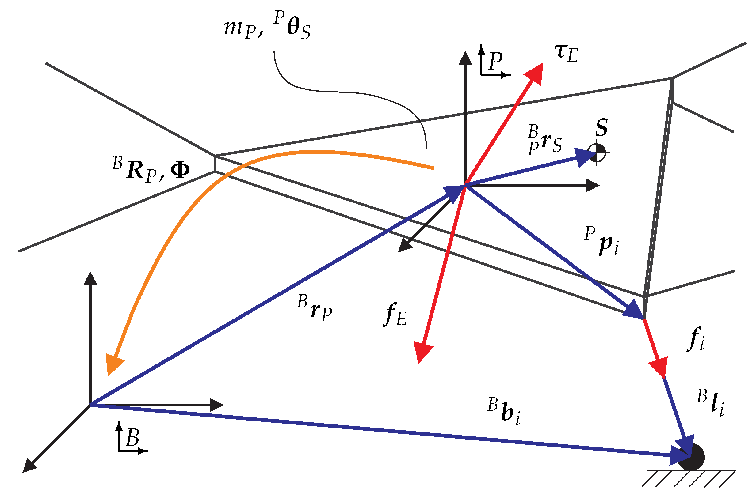
 is fixed to the platform, whereas the latter is referenced in the inertial system
  . The position of the platform and its orientation are denoted as row vectors. They are merged in the pose . The rotation matrix describes the platform orientation with respect to