Article

Optimization Design for the Planetary Gear Train of an Electric Vehicle under Uncertainties

1
School of Automotive Studies, Tongji University, Shanghai 201804, China
2
School of Mechanical Engineering, Tongji University, Shanghai 201804, China
3
College of Mechanical Engineering and Automation, Huaqiao University, Xiamen 361021, China
*
Author to whom correspondence should be addressed.
Actuators 2022, 11(2), 49; https://doi.org/10.3390/act11020049
Submission received: 9 December 2021 / Revised: 29 January 2022 / Accepted: 3 February 2022 / Published: 5 February 2022
(This article belongs to the Special Issue Actuators for Intelligent Electric Vehicles)

Abstract

:
The planetary gear train is often used as the main device for decelerating and increasing the torque of the drive motor of electric vehicles. Considering the lightweight requirement and existing uncertainty in structural design, a multi-objective uncertainty optimization design (MUOD) framework is developed for the planetary gear train of the electric vehicle in this study. The volume and transmission efficiency of the planetary gear train are taken into consideration as optimization objectives. The manufacturing size, material, and load input of the planetary gear train are considered as uncertainties. An approximate direct decoupling model, based on subinterval Taylor expansion, is applied to evaluate the propagation of uncertainties. To improve the convergence ability of the multi-objective evolutionary algorithm, the improved non-dominated sorting genetic algorithm II (NSGA-II) is designed by using chaotic and adaptive strategies. The improved NSGA-II has better convergence efficiency than classical NSGA-II and multi-objective particle swarm optimization (MOPSO). In addition, the multi-criteria decision making (MCDM) method is applied to choose the most satisfactory solution in Pareto sets from the multi-objective evolutionary algorithm. Compared with the multi-objective deterministic optimization design (MDOD), the proposed MUOD framework has better reliability than MDOD under different uncertainty cases. This MUOD method enables further guidance pertaining to the uncertainty optimization design of transportation equipment, containing gear reduction mechanisms, in order to reduce the failure risk.

1. Introduction

In recent years, electric vehicle technology has developed rapidly [1,2]. The planetary gear reducer is used in electric vehicles due to its high transmission efficiency and compact structure. Due to the space limitation of electric vehicles, the design of compact planetary gear trains has become a key issue. Numerous optimization methods are involved in the gear train design. For example, Parmar et al. [3] proposed a novel multi-objective optimization method, for planetary gear trains, using NSGA-II. Miler et al. [4] chose transmission volume and power loss as design objectives, and they optimized the parameters of the planetary gear train with multi-objective optimization. Sedak et al. [5] proposed a constrained multi-objective nonlinear optimization problem for planetary gearboxes, based on a hybrid element heuristic algorithm, considering gear volume, center distance, contact ratio, and power loss as optimization objectives. Patil et al. [6] proposed a multi-objective optimization strategy to minimize the total volume and power loss of the two-stage helical gearbox and spur gearbox. Compared to the single-objective optimization method with tribological constraints, the multi-objective optimization results in less power loss. Savsani et al. [7] used the particle swarm optimization algorithm, and the simulated annealing algorithm, to carry out the optimization design of the lightweight spur gear transmission system, and, resultingly, this method is deemed to be suitable for the single-objective or multi-objective optimization design of the multi-stage spur gear transmission. Considering the above research, the main challenge of gear transmission design is in reducing weight and power loss. At present, the optimization design method of planetary gear trains mainly considers the determining system parameters and implements the conventional deterministic optimization method. However, for practical engineering structures, many uncertainties are observed in the material properties, manufacturing, and measurement [8,9,10,11,12]. To obtain a reliable structural design, the uncertainties of the planetary gear train of electric vehicles need to be considered.
Uncertainty optimization in engineering design has gradually attracted attention [13,14,15]. For example, Xian et al. [16] proposed an effective analysis framework for stochastic optimization pertaining to non-linear viscous dampers of energy dissipation structures, which was applied to the uncertainty optimization of non-linear viscous dampers of suspension bridges. Lü et al. [17] proposed an efficient approach for the optimization design of dual uncertain structures, taking into account the dual robust design and the possibility of failure, quickly estimating the dual uncertain target of fuzzy random variables, and equivalently solving the possibility constraints involving fuzzy randomness. Baek et al. [18] developed a design method of a composite microwave absorbing structure using reliability-based optimization (RBO), which considers the failure probability. Compared with the results of deterministic optimization (DO), it was found that the total thickness of the reliability design method increased slightly, but RBO significantly reduced the failure probability. Fang et al. [19] developed an effective multi-objective uncertainty optimization program in order to design car doors. The program analyzed the impact of changing the uncertainty conditions and improving the reliability level, and it provided clear design information for decision-makers. Zhang et al. [20] proposed a reliable uncertainty optimization design route for obtaining optimal energy-absorbing structures. The study found that the solution obtained, by uncertainty optimization, sacrificed certain demand performance, but it was more reliable than deterministic design. The above studies have carried out the uncertainty optimization based on the probability model, which is highly dependent on statistical data. Considering that the distribution of uncertainty requires a lot of data, it is of a high cost to obtain effective probability data from a practical engineering perspective.
To overcome the limitation, of uncertainty optimization, due to the lack of data, some interval uncertainty modes have been gradually developed and applied to engineering optimization [21,22]. The interval uncertainty model mainly focuses on the upper and lower boundaries of uncertainty values, which is easier to implement than the probabilistic uncertainty model. Inuiguchi et al. [23] proposed a linear multi-objective strategy based on maximum and minimum regret criteria to solve the problem of interval uncertainty in the objective function. Fu et al. [24] developed a multi-objective direct structural optimization method for solving interval uncertainty. This method uses the satisfaction value of the interval possibility model to deal with non-linear uncertain constraints, and it judges the feasibility and infeasibility of individual design vectors. Wu et al. [25] proposed a non-probabilistic robust topology optimization method for interval uncertain structures. The method uses the Chebyshev interval inclusion function to realize the non-invasiveness of the interval algorithm. Wang et al. [26] developed an effective interval uncertain optimization design strategy using Legendre polynomial chaotic expansion, which is more efficient than the conventional method. Hou et al. [27] carried out the uncertainty optimization, pertaining to the energy efficiency of ships in icy areas, considering the interval parameters; the optimization results provided practical guidance for the energy-saving design of ships in the case of uncertainty in the actual environment. Yu et al. [28] regarded friction coefficient, material properties, and wear element thickness as interval uncertainty factors, and proposed an uncertainty optimization method for the noise suppression of the brake system.
The above studies have developed a highly effective uncertainty optimization method based on the interval model, and they have applied it to solve practical engineering problems. The interval model has been validated as a highly applicable uncertainty optimization method. Uncertainties in the manufacturing and operation of the planetary gear train of electric vehicles are unavoidable. The process of efficiently solving multi-objective uncertainty problems for the planetary gear train of electric vehicles is still a key issue. Therefore, a multi-objective uncertainty optimization design (MUOD) framework is developed for the planetary gear train of an electric vehicle in this study. Section 2 describes the detailed methodology of MUOD. Section 3 describes the design requirement of the planetary gear train of an electric vehicle. Section 4 shows the optimization results. The main conclusions are drawn in Section 5.

2. Methodology

2.1. Multi-Objective Uncertainty Optimization Problem

In general, the multi-objective deterministic optimization design (MDOD) model can be expressed as follows [29,30]:
{ min   f ( x ) = { f 1 ( x ) , f 2 ( x ) , , f q ( x ) } s . t .   { G i ( x ) 0 ,       i = 1 ,   2 , l h j ( x ) = 0 ,       j = 1 ,   2 , g               x { S }
In the formula, { f 1 , , f q } are the objective functions and q is the number of objectives. G i ( X ) is the inequality constraint and l is the number of its constraints; h j ( X ) is the equality constraint, and g is the number of its constraints; and { S } is the design space. Different from the conventional deterministic optimization, the uncertainties of optimization variables and other relevant design parameters need to be considered during actual processing. Stochastic probability models are often used to construct uncertainty models, but the distribution information of uncertainties is unknown due to the lack of test samples. Therefore, the interval uncertainty model is employed in this study [31]. The multi-objective deterministic optimization can be transformed into the interval uncertainty problem, as follows:
{ min   f ( x I , d I ) = { f 1 ( x I , d I ) , f 2 ( x I , d I ) , , f q ( x I , d I ) } s . t .   { G i ( x I , d I ) 0 ,       i = 1 ,     2 , l h j ( x I , d I ) = 0 ,       j = 1 ,   2 , g d I C d I R d I C d I C + d I R               x { S }
In the formula, x I and d I are interval design variables and other relevant design parameters, respectively. The superscripts I C and I R represent the nominal value and interval radius, respectively. The interval radius of an interval value reflects its fluctuation range and can be expressed as uncertainty deviation. When the design variables and other relevant parameters are interval values, the relationship of reliability-based possibility degree P d can be used to transform the interval uncertainty models into general non-interval models [31]. For the interval values A 1 , A 2 and A 1 A 2 ,
P d ( A 1 A 2 ) = { 0 , A 1 I L A 2 I U 0.5 · A 2 I U A 1 I L A 1 I U A 1 I L · A 2 I U A 1 I L A 2 I U A 2 I L , A 2 I L A 1 I L < A 2 I U A 1 I U A 2 I L A 1 I L A 1 I U A 1 I L + 0.5 · A 2 I U A 2 I L A 1 I U A 1 I L , A 1 I L < A 2 I L < A 2 I U A 1 I U A 2 I L A 1 I L A 1 I U A 1 I L + A 1 I U A 2 I L A 1 I U A 1 I L · A 2 I U A 1 I U A 2 I U A 2 I L + 0.5 · A 1 I U A 2 I L A 1 I U A 1 I L · A 1 I U A 2 I L A 2 I U A 2 I L , A 1 I L < A 2 I L A 1 I U < A 2 I U A 2 I U A 1 I U A 2 I U A 2 I L + 0.5 · A 1 I U A 1 I L A 2 I U A 2 I L , A 2 I L A 1 I L < A 1 I U A 2 I U 1 , A 1 I U < A 2 I L
The superscripts I L and I U represent the lower and the upper values, respectively. The reliability-based possibility degree of the interval level should be given beforehand based on the actual reliable problem. Therefore, the multi-objective uncertainty optimization model can be expressed as:
{ min   f ( x I C , d I C ) = { f 1 ( x I C , d I C ) , f 2 ( x I C , d I C ) , , f q ( x I C , d I C ) } s . t .   { P d _ i ( G i ( x I , d I ) 0 ) λ i ,       i = 1 ,   2 , l h j ( x I , d I ) = 0 ,       j = 1 ,   2 , g d I L d I C d I U               x { S }
In the formula, λ i is the requirement of reliability-based possibility degree, and it also represents the equivalent reliability with different constraints. The main optimization goals and constraints have been described in Section 3.
Nested optimization design is often used in interval uncertainty optimization, which treats the uncertainty analysis problem as an internal optimization problem. The purpose of inner optimization is to evaluate the propagation of uncertainty and feed it back to the outer optimization route. It is worth considering that adding a new optimization solver will cause low computational efficiency. Therefore, Taylor expansion, as an effective decoupling method, is applied to analyze the propagation of uncertainty in this study [32]. The constraint function G i ( x I , d I ) can be approximately constructed by first-order Taylor expansion, that is:
G i ( x I , d I ) G i ( x I C , d I C ) + i = 1 n G i ( x I C , d I C ) x i I C x i I R + j = 1 m G i ( x I C , d I C ) d i I C d i I R
Therefore, the lower and upper bounds of the constraint function can be expressed as follows:
G i I L ( x I , d I ) G i ( x I C , d I C ) | i = 1 n G i ( x I C , d I C ) x i I C | x i I R | j = 1 m G i ( x I C , d I C ) d i I C | d i I R
G i I U ( x I , d I ) G i ( x I C , d I C ) + | i = 1 n G i ( x I C , d I C ) x i I C | x i I R + | j = 1 m G i ( x I C , d I C ) d i I C | d i I R
Generally, the Taylor formula can achieve the best approximation in the case of a small interval uncertainty. Further, the calculation accuracy can be improved by establishing a subinterval to compensate for the nonlinear approximation error. For the uncertainty values U ,
U s = [ U I L + 2 ( s 1 ) U I R S _ n , U I L + 2 s U I R S _ n ] ,   s = 1 , 2 , , S _ n
In the formula, U s and S _ n are the sth subinterval and the subinterval number, respectively. The subinterval number can be determined by referring to the number of uncertain parameters. The interval range of constraint function G i ( U ) is expressed as follows:
G i ( U ) = [ min ( G i I L ( U 1 ) G i I L ( U s ) ) , max ( G i I U ( U 1 ) G i I U ( U s ) ) ]
G i I L ( U ) = min ( G i I L ( U 1 ) G i I L ( U s ) ) ,   G i I U ( U ) = max ( G i I U ( U 1 ) G i I U ( U s ) )
Through the above interval uncertainty analysis method, the uncertain information of constraint function G i ( U ) can be solved by using the approximate direct decoupling method.

2.2. Improved Evolutionary Algorithm

The classical non-dominated sorting genetic algorithm (NSGA-II) generally uses the random function to generate the initial population [33], and its population uniformity is poor. The crossover probability and mutation probability of classical NSGA-II are set to a fixed value, respectively, and the optimization algorithm falls into the premature problem. Therefore, this paper adopts the improved NSGA-II designed by using chaotic and adaptive evolutionary strategies in order to obtain the multi-objective solution set.
Here, a chaotic strategy is used to generate the initial population of a multi-objective evolutionary algorithm, which can improve the diversity of the population. Tent map is one of the most commonly used mapping functions for generating chaotic sequences [34]. Here, the main steps of population chaos initialization and assignment, using the Tent mapping method, are as follows:
Step 1: Randomly generate an N-dimensional random number vector, X 1 = ( X 11 , X 1 j , X 1 N v ) , X 1 j [ 0 , 1 ] , where N v is the number of optimization variables.
Step 2: The improved Tent mapping method is used to calculate the chaotic component of each optimized variable, as follows:
X ( i + 1 , j ) = { T ( X ( i , j ) ) + 0.1 · rand ( 0 , 1 ) , X ( i , j ) [ 0 , 0.25 , 0.5 , 0.75 ]   or   X ( i , j ) = X ( i δ , j ) ,   δ [ 1 , 2 , 3 , 4 ] T ( X ( i , j ) ) , else
T ( X ( i , j ) ) = { 2 X ( i , j ) , 0 X ( i , j ) 0.5 2 ( 1 X ( i , j ) ) , 0.5 < X ( i , j ) 1
In the formula, i = 1, 2, …, P s , and P s is the population size; j = 1, 2, …, Nv.
Step 3: Substitute each chaotic component obtained in Step 2 into the real range of each optimization variable, as follows:
x ( i , j ) = x j l o w e r + X ( i , j ) ( x j u p p e r x j l o w e r )
In the formula, x j l o w e r and x j u p p e r are the lower and upper bounds of the j th optimized variable respectively.
Here, the adaptive evolutionary strategy mainly improves the crossover and mutation operators. The adaptive crossover probability and mutation probability are generated according to the number of iterations, which is helpful to accelerate the convergence of optimization. In this study, the exponential function is applied to the adaptive adjustment mode of crossover probability and mutation probability. The calculation formula is described as follows:
{ p c ( n i ) = 1 1.5 e ( n i n t ) 1 + e ( n i n t ) p c ( 0 )   p m ( n i ) = 1.5 e ( n i n t ) 1 + e ( n i n t ) p m ( 0 )         ,
In the formula, p c ( n i ) and p m ( n i ) are the crossover probability and mutation probability at the n i th iteration; p c ( 0 ) and p m ( 0 ) are the initial crossover probability and mutation probability respectively; n t is the total evolutionary generation.

2.3. Multi-Criteria Decision Making (MCDM) Method

Usually, the Pareto solution set in multi-objective optimization can provide decision-makers with numerous feasible design schemes at the early stage of design, but it cannot directly obtain the most satisfactory solution. In addition, the weight method aggregates multi-objective optimization into a single comprehensive objective to obtain the ideal optimal solution. However, although some decision-makers are full of engineering experience, it is nonetheless difficult to assign the optimal weight to each optimization objective. Therefore, as a multi-criteria decision making (MCDM) model, grey relational analysis (GRA) will be applied to select the most satisfactory scheme in Pareto sets [35,36,37]. Here, the GRA with entropy weight method is proposed to identify the most satisfactory solution. The normalization method can be adopted in the grey relation analysis, depending on the characteristics of the original sequence. When the target value of the original sequence is “the larger the better”, the original sequence can be normalized as:
y i * ( k ) = y i ( k ) min [ y i ( k ) ] max [ y i ( k ) ] min [ y i ( k ) ]
In the formula, y i * ( k ) is a new sequence after normalization; max [ y i ( k ) ] is the maximum value of the original sequence; and min [ y i ( k ) ] is the minimum value of the original sequence. When the target value of the original sequence is “the smaller the better”, the original sequence can be normalized as:
y i * ( k ) = max [ y i ( k ) ] y i ( k ) max [ y i ( k ) ] min [ y i ( k ) ]
After normalization, the grey relational coefficient γ i ( k ) , which is used to quantify the relationship between the target and actual normalized results, can be formulated as [26]:
γ i ( k ) = m i n ρ m a x o i ( k ) + ρ m a x
In the formula, o i ( k ) is the deviation between reference sequence o i ( k ) and the compared sequence x i * ( k ) , as follows:
o i ( k ) = y i * ( k ) y o ( k )
m i n = min j i min k y j * ( k ) y o ( k )
m a x = max j i max k y j * ( k ) y o ( k )
ρ is the distinguishing coefficient, ρ [ 0 , 1 ] , and ρ = 0.5 in this study. After obtaining the grey relational coefficient, the grey relational grade c i is presented in a weighted sum of the grey relational coefficients, as follows:
c i = 1 n k = 1 n γ i ( k )
For the actual engineering requirements, the effect of each criterion on the design objectives is not exactly the same; resultingly, Equation (25) can be modified to
{ c i = j = 1 n w k γ i ( k ) k = 1 n w k = 1
In the formula, w k is a weight of k th criterion. In this study, w j is determined by the entropy weight method. The weight is calculated by using the entropy weight method according to the variation degree of each criterion.
Different from the analytic hierarchy process (AHP) [38], the entropy weight method can objectively obtain the weight of each criterion according to the amount of information provided by each criterion and the correlation between the criteria, which overcomes the subjectivity in determining the weight of the criterion. Assuming O i k is the i th alternative value of the k th evaluation criterion, and the initial evaluation matrix is O = ( O i k ) m × n .
The proportion of the i th alternative value of the k th evaluation criterion is [39]:
P i k = O i k i = 1 m O i k ( i = 1 , 2 , m ; k = 1 , 2 , , n )
The entropy e k of the k th criterion is:
e k = i = 1 m p i k ln ( p i k ) / ln ( m )
When p i k is equal to 0, to ensure that ln ( p i k ) is meaningful, Equation (23) can be modified to:
P i k = O i k + 1 m + i = 1 m O i k .
Therefore, the entropy weight of the k th criterion can be expressed as follows:
w k = 1 e k k = 1 n ( 1 e k ) .

2.4. Main Processes of MUOD

The main steps of the multi-objective uncertainty optimization design (MUOD) framework are as shown in Figure 1:
Step 1: Define multi-objective optimization problems, optimization variables, objectives, and constraint functions. This step is similar to conventional deterministic multi-objective optimization.
Step 2: The interval optimization problem is transformed into a deterministic optimization problem using the relationship of reliability-based possibility degree. It should be noted that the interval uncertainty transformation mainly aims at the inequality constraints in the multi-objective optimization model. The lower and upper values of constraint functions can be solved directly by using the approximate direct decoupling method.
Step 3: The execution process of the multi-objective evolutionary algorithm. An improved multi-objective evolutionary algorithm is applied to calculate the transformed mathematical model in Step 2. The improved NSGA-II is designed in Section 2.2. The initial crossover probability and mutation probability are 0.8 and 0.1.
Step 4: The execution process of the MCDM method. The MCDM method is described in Section 2.3. The GRA with entropy weight method is applied to choose the most satisfactory solution in Pareto sets. The objective weight is calculated by using the entropy weight method, and the grey relational grade is calculated by Equation (26).

3. Design Requirements of the Planetary Gear Train

3.1. Main Design Variables and Optimization Objectives

The electric drive system and its planetary gear train are shown in Figure 2. The planetary gear train is used to reduce the speed and increase the output torque of the motor. Since the helical gear has the advantages of good meshing, stable transmission, and low noise, the helical planetary gear train is designed in this study. The main parameters of an electric commercial vehicle are shown in Table 1, which are provided by a vehicle company. The transmission ratio of the gear and the final output torque can be calculated according to the vehicle parameters.
The planetary gear train should be compact; that is, the overall volume of the planetary gear train should be small enough to facilitate the arrangement of the electric drive system in the chassis of the electric vehicle. Smaller gear volume corresponds to lighter weight, which is more conducive to the improvement of energy efficiency. Therefore, the volume of the helical planetary gear train is used as the optimization objective function. To simplify the calculation, the volume v of the ring gear is chosen as the design objective, as follows:
v = 1 4 π b d r 2 ,
In the formula, d r is the pitch circle diameter of the ring gear; b is the tooth width. In general, the power loss in gear transmission mainly includes the friction loss caused by gear tooth surface meshing, the bearing loss, and the stirring loss of lubricating oil. The meshing friction power loss is the main reason for the gear transmission power loss. Therefore, the transmission efficiency, considering the meshing friction power loss, is regarded as the second design objective. The planetary gear train mainly includes external and internal meshing of the gear, as shown in Figure 3a,b.
Here, the transmission efficiency η e x of external meshing can be expressed as [40]:
η e x = 1 μ Z p p t ( 1 Z s + 1 Z p ) f e x ( ε ) R b p μ R p ( ε e i ε e o ) sin α t + μ p t f e x ( ε )
In the formula, μ is the friction coefficient; Z s is the number of teeth of the sun gear; Z p is the number of teeth of the planet gear; α t is the transverse pressure angle; p t is the transverse circular pitch; R b p and R p are the base circle radius and pitch circle radius of planet gear respectively; and ε e i and ε e o are the meshing in and meshing out contact ratio of the gear external meshing, respectively, as follows:
ε e i = Z s ( t g α a s t g α ) 2 π
ε e o = Z p ( t g α a p t g α ) 2 π
In the formula, α is the working pressure angle; α a s and α a p are the tooth top pressure angle of sun gear and planet gear respectively. As shown in Figure 3c, assuming that the load distribution coefficient in the regions “a-b” and “c-d” is 0.5, f e x ( ε ) can be expressed as follows:
f e x ( ε ) = 0.5 ( ε e i 2 + ε e o 2 ε e i ε e o + 1 )
Similarity, the transmission efficiency η i n of internal meshing can be expressed as follows [40]:
η i n = 1 μ Z P p t ( 1 Z p 1 Z r ) f i n ( ε ) R b p μ R p ( ε i i ε i o ) sin α t + μ p t f i n ( ε )
In the formula, Z r is the is the number of teeth of the ring gear; ε i i and ε i o are the meshing in and meshing out contact ratio of the gear external meshing, respectively, as follows:
ε i i = R a p 2 R b p 2 R p sin α t p t
ε i o = R r sin α t R a r 2 R b r 2 p t
Same as Equation (31), assuming that the load distribution coefficient is 0.5, f i n ( ε ) can be expressed as follows:
f i n ( ε ) = 0.5 ( ε i i 2 + ε i o 2 ε i i ε i o + 1 ) .
Therefore, the transmission efficiency η p of the planetary reduction gear train can be expressed as follows [41]:
η p = R s 2 ( R r R p ) + [ 1 R s 2 ( R r R p ) ] η e x η i n
In this study, six main parameters are considered as design variables to find the minimum volume and maximum transmission efficiency. These design variables X v include the teeth number of the sun gear Z s , the teeth number of the planet gear Z p , the teeth number of the ring gear Z r , helix angle β , face width b , and normal module m n . Z s , Z p , and Z r are integers, β and b are continuous, and m n is discrete. The alternative modulus m n is shown in Equation (38). Table 2 shows the detailed information of all design variables.
X v = { Z s , Z p , Z r , β , b , m n } ,
m n { 2 ,   2.25 ,   2.5 ,   2.75 ,   3 ,   3.5 ,   4 ,   4.5 ,   5 }

3.2. Main Design Constraints

The gear design should meet the specified constraints to meet the actual geometric, load, and material requirements. The main constraints of the planetary gear train in this study are as follows.

3.2.1. Equally Spaced Planets

To prevent the gear teeth from interfering with the mating gear, the gear teeth of all gears must mesh with the center gear teeth at the same time. The installation requirement needs to meet the following conditions:
Z s + Z r n p = integer ,
In the formula, n p is the number of planet gears.

3.2.2. Equally Spaced Planets

According to the actual power requirement of an electric vehicle, the transmission ratio r i of the planetary gear train needs to meet the following conditions:
4.1 r i 4.6 ,
r i = 1 + Z r Z s .

3.2.3. Tooth Width Coefficient

The size of the tooth width is related to the strength of the gear; the larger the tooth width, the higher the strength. However, it should be noted that, if the tooth width is too large, there will be a larger number of tooth contact errors as well as a more uneven load distribution in the tooth direction. Therefore, it is critical to select an applicable tooth width. Here, the tooth width coefficient Φ d is the primary indicator of the tooth width design, which needs to meet the following constraints [42]:
0.7 Φ d 4 ,
Φ d = b d s .

3.2.4. Minimum Teeth of No-Undercut

Gear undercutting not only weakens the root of gear teeth while reducing the bending strength, but it also reduces the coincidence degree. Therefore, undercutting should be avoided in the gear design stage. The minimum number of teeth without undercutting of the helical cylindrical gear needs to meet the following constraints:
{ Z s , Z p , Z r } 17 cos 3 β .

3.2.5. Concentric Constraint

The center distance between sun gear, ring gear, and planetary gear should be equal. The concentric constraint is:
Z s + Z p = Z r Z p .

3.2.6. Adjacency Constraint

To prevent the planet gears from colliding with each other, it is necessary to ensure that the planet gears have a certain clearance on their connecting lines; that is, the sum of the tooth top circle radius of two adjacent planetary gears shall be less than the center distance of two adjacent planetary gears. The adjacency constraint is:
d a p < 2 l s p sin ( π n p   ) ,
In the formula, d a p is the addendum circle diameter of planet gear; l s p is the center distance between the sun gear and the planet gear.

3.2.7. Contact Stress Requirement

The planetary gear train should be able to resist material failure (deformation and fracture) during contact behavior. The real contact stress requirement σ c needs to meet the following constraint [43]:
σ c = 0.418 F n E ( 1 ρ a + 1 ρ p ) / b [ σ c ]
In the formula, F n is the normal load; E is the elastic modulus of the material; [ σ c ] is the allowable contact stress, and the gear material is 40Cr in this study; and ρ a and ρ p denote the radius of curvature at the nodes of the driving and driven gears, respectively. In the planetary gear system, the contact stress mainly occurs between the sun gear and the planetary gear, and between the planetary gear and the ring gear. However, considering that the dangerous position is usually present between the sun gear and the planetary gear, this study will focus on the contact stress between the sun gear and the planetary gear.

3.2.8. Bending Stress Requirement

The bending stress requirement σ w _ s needs to meet the following constraint [42]:
σ w _ s = 2 T t K σ / d b π m n Y K ε [ σ w _ s ] ,
In the formula, T t is the transmitted torque; d is the pitch circle diameter; K σ is the stress concentration factor of contact ratio, K σ   = 1.5; K ε is the influence factor of contact ratio, K ε   = 2.0; and Y is the tooth profile coefficient. According to the empirical formula, the tooth profile coefficient of the sun gear can be expressed as follows:
Y = 0.1735 0.717 Z v 8.37 Z v 2 + 53.84 Z v 3 ,
In the formula, Z v is a virtual number of teeth pertaining to the helical gear, Z v = Z / cos 3 β .

4. Optimization Results and Discussions

In this study, the helix angle β , face width b , elastic modulus E , and input torque T are considered uncertain. The uncertain helix angle β and face width b are regarded as the uncertainty of manufacturing size. The uncertain elastic modulus E is regarded as the uncertainty of material. The uncertain input torque T is regarded as the uncertainty of load input. This study defines three uncertainty cases with different uncertainty deviations, which correspond to different degrees of uncertainty deviations, as shown in Table 3. Therefore, the constraint functions related to the above uncertain values can be regarded as uncertainty constraints. Uncertainty constraints mainly include tooth width coefficient, minimum teeth of no-undercut, adjacency constraint, contact stress constraint, and bending stress constraint. The nominal values of elastic modulus E I C and input load T t I C are 210 GPa and 3936 N·m, respectively. All requirements of reliability-based possibility degree λ are defined as 0.8.
Here, the classical NSGA-II and multi-objective particle swarm optimization (MOPSO) are implemented in order to explore the feasibility of the improved NSGA-II. The initial population size is 400, the maximum number of iterations is 200, and the objective number of non-dominated solutions is 200. Figure 4 shows the iterative history of MDOD by using MOPSO, NSGA-II, and improved NSGA-II. The number of non-dominated solutions obtained by improved NSGA-II increases steadily, and improved NSGA-II can obtain non-dominated solutions more efficiently than MOPSO and NSGA-II. Therefore, the improved NSGA-II designed in this paper is effective, and it contains better optimization potential than the classical NSGA-II and MOPSO. The improved NSGA-II will be implemented for MUOD.
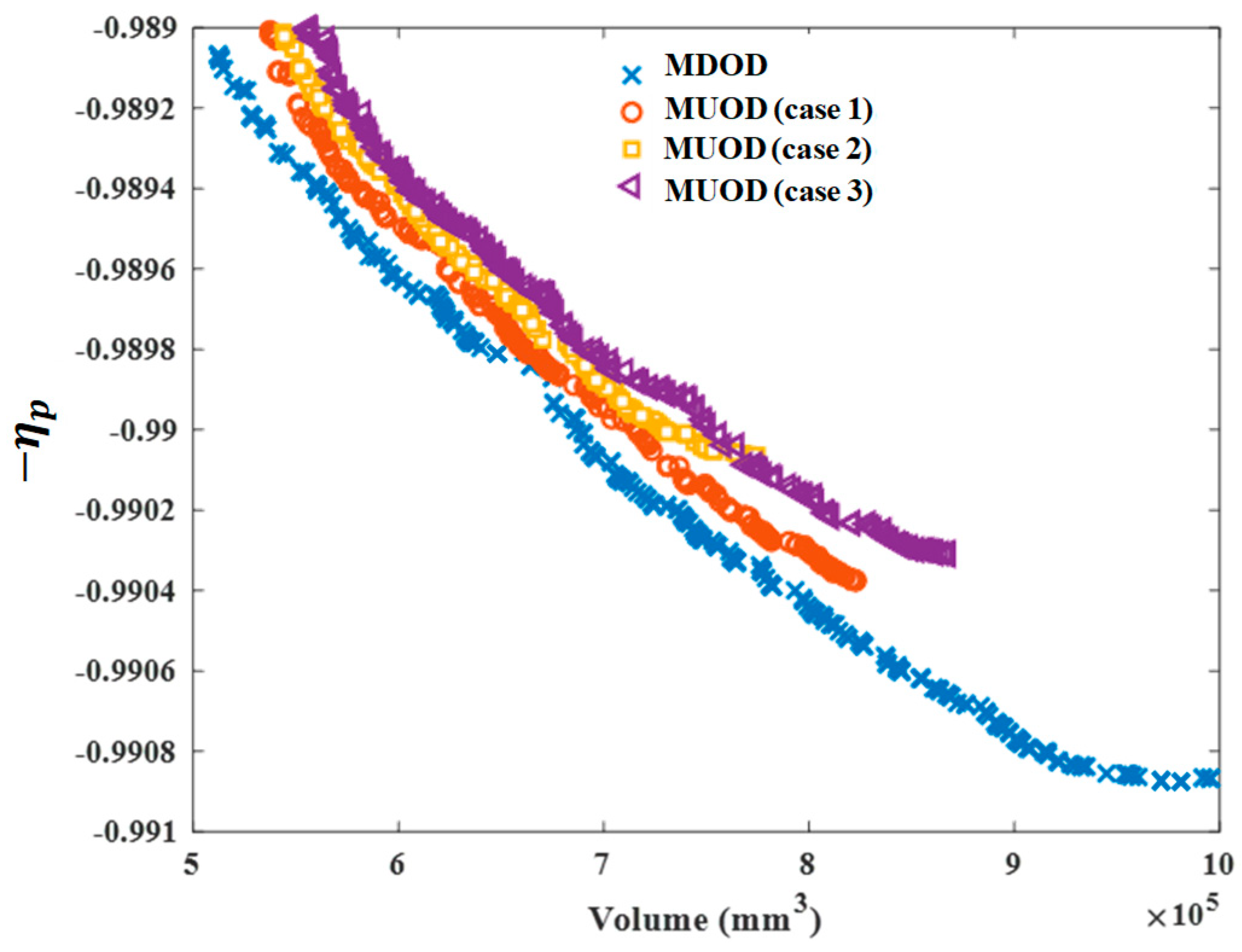
Figure 5 shows the optimal Pareto solution sets of MDOD and MUOD. There is an intense conflict between volume and transmission efficiency, which cannot achieve the common optimization; that is, the further improvement of one objective will inevitably worsen the other objective. The Pareto solution set of deterministic optimization design is lower than that of uncertainty optimization design, and the optimization objective of deterministic optimization design is better than uncertainty optimization design. In general, the inequality constraint of deterministic optimization is mainly concentrated near the constraint boundary, so its Pareto solution set has more loose space, and it is easier to obtain the better solution. It should be noted that, with the increase of uncertainty, the optimization results of MUOD tend to be conservative. To obtain the optimal solutions in different multi-objective optimization models, this study makes a trade-off analysis on the Pareto solution set by using the MCDM method. The optimal results of MDOD and MUOD are shown in Appendix A. Table A1 presents the optimization results of MDOD, and Table A2, Table A3 and Table A4 present the optimization results of MUOD. The alternatives of different optimization methods are sorted according to the grey correlation degree, and the optimal solutions of all optimization methods are shown in bold. It is found that all moduli are 2, which means that the optimization space for modulus is small. Here, three uncertainty cases are substituted into all optimization results, and the obtained constraints are shown in Table 4. The optimal result of MDOD shows that the λ of the upper bound of tooth width coefficient is less than 0.8, and the bending stress is less than 0.8 when the uncertainty range is the largest (Case 3). From another perspective, the bending stress constraint and the tooth width coefficient constraint are the most prone to failure types. In the three uncertainty cases, MUOD meets the reliability requirements for all uncertainty constraints. A higher λ indicates that the farther the optimization result is from the boundary of the inequality constraint, the higher its reliability. Compared with the conventional MDOD, the MUOD proposed in this study can design a more reliable planetary gear train and reduce the risk of constraint failure. The results show that MUOD sacrifices certain performance, but it is more reliable than MDOD.

5. Conclusions

In order to design a reasonable planetary reduction gear system, matching the electric vehicle motor, this study proposes a multi-objective uncertainty optimization design (MUOD) framework for the planetary gear train of an electric vehicle. An approximate direct decoupling model, based on subinterval Taylor expansion, is applied to evaluate the propagation of uncertainties; the improved evolutionary algorithm is designed by using chaotic and adaptive evolutionary strategies. The volume and transmission efficiency of the planetary gear are optimization objectives. The optimization results of MUOD show that the Pareto front gradually moves to the upper right corner with the uncertainty increases. The most satisfactory solutions (improving lightweight and improving transmission efficiency) pertaining to different multi-objective optimization models can be obtained by the MCDM method. Compared with the conventional multi-objective deterministic optimization design (MDOD) method, the uncertainty optimization design of the planetary gear train sacrifices certain performance. When the reliability-based possibility degree λ is defined as 0.8, the optimization results of MUOD always meet this requirement, but at least one constraint violates this requirement in MDOD. As the degree of uncertainty increases, the optimization results of MUOD tend to be conservative, but MUOD is more reliable than MDOD. The uncertainty of planetary gear trains of electric vehicles is very complex in actual working conditions. The MUOD framework proposed in this study is able to continue carrying out optimization design with more complex high dimension uncertainties and objectives in order to ensure that the structure has better potential to resist the risk of failure.

Author Contributions

Writing—review & editing, X.X.; writing—original draft, X.X., J.C.; software, X.X., J.C., Z.L., Y.Q., X.C., Y.Z. and Y.X.; methodology, X.X., J.C., Z.L., Y.Q., X.C., Y.Z., Y.X. and Y.L.; investigation, X.X., Z.L., Y.Q., Y.Z., Y.X. and Y.L.; project administration, X.C. All authors have read and agreed to the published version of the manuscript.

Funding

This research was funded by “Project of Shanghai Science and Technology Committee, grant number 20511104602” and “Prospective Technology Project of Nanchang Intelligent New Energy Vehicle Research Institute, grant number 17092380013”.

Conflicts of Interest

The authors declare no conflict of interest.

Appendix A. Optimization Results

Table A1. Optimization results from MDOD.
Ranking b (mm) β (°) m n (mm) Z p Z r Z s c i
131.6024.9122264200.9333
231.6325.3222264200.9195
331.6325.4622264200.9153
432.0022.5222571210.6758
532.0022.5522571210.6753
631.9422.6922571210.6752
732.0022.5622571210.6751
831.9622.6622571210.6751
931.9522.6922571210.6748
1032.0122.8322571210.6709
Table A2. Optimization results from MUOD (Case 1).
Ranking b (mm) β (°) m n (mm) Z p Z r Z s c i
134.8122.3822470220.9333
234.8122.3922470220.9331
334.8722.3822470220.9247
434.8622.5122470220.9241
534.8722.5922470220.9201
634.8722.6022470220.9200
734.8722.6122470220.9193
834.9522.6722470220.9106
935.1122.7022470220.8968
1035.1122.7422470220.8951
Table A3. Optimization results from MUOD (Case 2).
Ranking b (mm) β (°) m n (mm) Z p Z r Z s c i
132.5622.3122264200.9333
232.5622.5022264200.9292
332.6922.5722264200.9214
432.7322.6722264200.9175
532.6923.0122264200.9117
632.6923.0222264200.9114
732.6923.0322264200.9114
832.7323.1622264200.9064
932.7323.2122264200.9055
1032.7323.2822264200.9039
Table A4. Optimization results from MUOD (Case 3).
Ranking b (mm) β (°) m n (mm) Z p Z r Z s c i
134.8422.3322367210.9333
234.8622.3322367210.9319
335.1523.0522367210.8859
435.1523.1422367210.8823
535.1723.1722367210.8798
635.1723.1822367210.8795
735.2723.2822367210.8699
835.2723.4222367210.8652
935.3323.4622367210.8592
1035.3823.4922367210.8558

References

  1. Wang, R.; Chen, Y.; Feng, D.; Huang, X.; Wang, J. Development and performance characterization of an electric ground vehicle with independently actuated in-wheel motors. J. Power Sources 2011, 196, 3962–3971. [Google Scholar] [CrossRef]
  2. Hang, P.; Chen, X. Towards autonomous driving: Review and perspectives on configuration and control of four-wheel independent drive/steering electric vehicles. Actuators 2021, 10, 184. [Google Scholar] [CrossRef]
  3. Parmar, A.; Ramkumar, P.; Shankar, K. Macro geometry multi-objective optimization of planetary gearbox considering scuffing constraint. Mech. Mach. Theory 2020, 154, 104045. [Google Scholar] [CrossRef]
  4. Miler, D.; Žeželj, D.; Lončar, A.; Vučković, K. Multi-objective spur gear pair optimization focused on volume and efficiency. Mech. Mach. Theory 2018, 125, 185–195. [Google Scholar] [CrossRef]
  5. Sedak, M.; Rosić, B. Multi-objective optimization of planetary gearbox with adaptive hybrid particle swarm differential evolution algorithm. Appl. Sci. 2021, 11, 1107. [Google Scholar] [CrossRef]
  6. Patil, M.; Ramkumar, P.; Shankar, K. Multi-objective optimization of the two-stage helical gearbox with tribological constraints. Mech. Mach. Theory 2019, 138, 38–57. [Google Scholar] [CrossRef]
  7. Savsani, V.; Rao, R.V.; Vakharia, D.P. Optimal weight design of a gear train using particle swarm optimization and simulated annealing algorithms. Mech. Mach. Theory 2010, 45, 531–541. [Google Scholar] [CrossRef]
  8. Sun, G.; Zhang, H.; Fang, J.; Li, G.; Li, Q. A new multi-objective discrete robust optimization algorithm for engineering design. Appl. Math. Model 2018, 53, 602–621. [Google Scholar] [CrossRef]
  9. Xu, X.; Chen, X.; Liu, Z.; Yang, J.; Xu, Y.; Zhang, Y.; Gao, Y. Multi-objective reliability-based design optimization for the reducer housing of electric vehicles. Eng. Optim. 2021, 1–17. [Google Scholar] [CrossRef]
  10. Xu, X.; Chen, X.; Liu, Z.; Xu, Y.; Zhang, Y. Reliability-based design for lightweight vehicle structures with uncertain manufacturing accuracy. Appl. Math. Model 2021, 95, 22–37. [Google Scholar] [CrossRef]
  11. Fang, J.; Gao, Y.; Sun, G.; Xu, C.; Li, Q. Multiobjective robust design optimization of fatigue life for a truck cab. Reliab. Eng. Syst. Saf. 2015, 135, 1–8. [Google Scholar] [CrossRef]
  12. Dawood, T.; Elwakil, E.; Novoa, H.M.; Delgado, J.F.G. Soft computing for modeling pipeline risk index under uncertainty. Eng. Fail. Anal. 2020, 117, 104949. [Google Scholar] [CrossRef]
  13. Li, W.; Gao, L.; Xiao, M. Multidisciplinary robust design optimization under parameter and model uncertainties. Eng. Optim. 2020, 52, 426–445. [Google Scholar] [CrossRef]
  14. Chen, Z.; Li, T.; Xue, X.; Zhou, Y.; Jing, S. Fatigue reliability analysis and optimization of vibrator baseplate based on fuzzy comprehensive evaluation method. Eng. Fail. Anal. 2021, 127, 105357. [Google Scholar] [CrossRef]
  15. Yuan, R.; Tang, M.; Wang, H.; Li, H. A Reliability analysis method of accelerated performance degradation based on bayesian strategy. Access 2019, 7, 169047–169054. [Google Scholar] [CrossRef]
  16. Xian, J.; Su, C. Stochastic optimization of uncertain viscous dampers for energy-dissipation structures under random seismic excitations. Mech. Syst. Signal Process. 2022, 164, 108208. [Google Scholar] [CrossRef]
  17. Lü, H.; Yang, K.; Huang, X.; Yin, H.; Shangguan, W.-B.; Yu, D. An efficient approach for the design optimization of dual uncertain structures involving fuzzy random variables. Comput. Methods Appl. Mech. Eng. 2020, 371, 113331. [Google Scholar] [CrossRef]
  18. Baek, S.M.; Lee, W.J. Design method for radar absorbing structures using reliability-based design optimization of the composite material properties. Compos. Struct. 2021, 262, 113559. [Google Scholar] [CrossRef]
  19. Fang, J.; Gao, Y.; Sun, G.; Li, Q. Multiobjective reliability-based optimization for design of a vehicledoor. Finite Elem. Anal. Des. 2013, 67, 13–21. [Google Scholar] [CrossRef]
  20. Zhang, Y.; Xu, X.; Sun, G.; Lai, X.; Li, Q. Nondeterministic optimization of tapered sandwich column for crashworthiness. Thin Walled Struct. 2018, 122, 193–207. [Google Scholar] [CrossRef]
  21. Li, F.; Luo, Z.; Sun, G.; Zhang, N. An uncertain multidisciplinary design optimization method using interval convex models. Eng. Optim. 2013, 45, 697–718. [Google Scholar] [CrossRef]
  22. Xu, X.; Chen, X.; Liu, Z.; Zhang, Y.; Xu, Y.; Fang, J.; Gao, Y. A feasible identification method of uncertainty responses for vehicle structures. Struct. Multidiscip. Optim. 2021. [Google Scholar] [CrossRef]
  23. Inuiguchi, M.; Sakawa, M. Minimax regret solution to linear programming problems with an interval objective function. Eur. J. Oper. Res. 1995, 86, 526–536. [Google Scholar] [CrossRef]
  24. Fu, C.; Liu, Z.; Deng, J. A direct solution framework for structural optimization problems with interval uncertainties. Appl. Math. Model. 2020, 80, 384–393. [Google Scholar] [CrossRef]
  25. Wu, J.; Gao, J.; Luo, Z.; Brown, T. Robust topology optimization for structures under interval uncertainty. Adv. Eng. Softw. 2016, 99, 36–48. [Google Scholar] [CrossRef]
  26. Wang, L.; Yang, G.; Li, Z.; Xu, F. An efficient nonlinear interval uncertain optimization method using legendre polynomial chaos expansion. Appl. Soft Comput. 2021, 108, 107454. [Google Scholar] [CrossRef]
  27. Hou, Y.; Xiong, Y.; Zhang, Y.; Liang, X.; Su, L. Vessel energy efficiency uncertainty optimization analysis in ice zone considering interval parameters. Ocean Eng. 2021, 232, 109114. [Google Scholar] [CrossRef]
  28. Lü, H.; Yu, D. Brake squeal reduction of vehicle disc brake system with interval parameters by uncertain optimization. J. Sound Vib. 2014, 333, 7313–7325. [Google Scholar] [CrossRef]
  29. Fonseca, C.M.; Fleming, P.J. Multiobjective optimization and multiple constraint handling with evolutionary algorithms I. A unified formulation. Trans. Syst. Man Cybern. Part A Syst. Hum. 1998, 28, 26–37. [Google Scholar] [CrossRef] [Green Version]
  30. Fonseca, C.M.; Fleming, P.J. Multiobjective optimization and multiple constraint handling with evolutionary algorithms II. Application example. Trans. Syst. Man Cybern. Part A Syst. Hum. 1998, 28, 38–47. [Google Scholar] [CrossRef]
  31. Jiang, C.; Han, X.; Liu, G.R.; Liu, G.P. A nonlinear interval number programming method for uncertain optimization problems. Eur. J. Oper. Res. 2008, 188, 1–13. [Google Scholar] [CrossRef]
  32. Meng, D.; Hu, Z.; Guo, J.; Lv, Z.; Xie, T.; Wang, Z. An uncertainty-based structural design and optimization method with interval taylor expansion. Structures 2021, 33, 4492–4500. [Google Scholar] [CrossRef]
  33. Deb, K.; Pratap, A.; Agarwal, S.; Meyarivan, T. A fast and elitist multiobjective genetic algorithm: NSGA-II. Trans. Evol. Comput. 2002, 6, 182–197. [Google Scholar] [CrossRef] [Green Version]
  34. Paknejad, P.; Khorsand, R.; Ramezanpour, M. Chaotic improved PICEA-g-based multi-objective optimization for workflow scheduling in cloud environment. Futur. Gener. Comput. Syst. 2021, 117, 12–28. [Google Scholar] [CrossRef]
  35. Ju-Long, D. Control problems of grey systems. Syst. Control Lett. 1982, 1, 288–294. [Google Scholar] [CrossRef]
  36. Li, C.H.; Tsai, M.J. Multi-objective optimization of laser cutting for flash memory modules with special shapes using grey relational analysis. Opt. Laser Technol. 2009, 41, 634–642. [Google Scholar] [CrossRef]
  37. Wei, G.-W. Gray relational analysis method for intuitionistic fuzzy multiple attribute decision making. Expert Syst. Appl. 2011, 38, 11671–11677. [Google Scholar] [CrossRef]
  38. Emovon, I.; Oghenenyerovwho, O.S. Application of MCDM method in material selection for optimal design: A review. Results Mater. 2020, 7, 100115. [Google Scholar] [CrossRef]
  39. Kumar, R.; Singh, S.; Bilga, P.S.; Singh, J.; Singh, S.; Scutaru, M.-L.; Pruncu, C.I. Revealing the benefits of entropy weights method for multi-objective optimization in machining operations: A critical review. J. Mater. Res. Technol. 2021, 10, 1471–1492. [Google Scholar] [CrossRef]
  40. Li, C.; Qin, D.T.; Shi, W.K. Reference Efficiency of Planetary Gear Train. J. Chongqing Uni. 2006, 29, 11–14. [Google Scholar]
  41. Chen, Y.; Ishibashi, A.; Sonoda, K.; Matubara, M. Studies on noise and vibration of planetary gear drives for automatic transmission of passenger cars. Trans. Jpn. Soc. Mech. Eng. Ser. C 2000, 66, 634–639. [Google Scholar] [CrossRef] [Green Version]
  42. Lin, Z.; Zhang, J.; Xu, X.; Chen, J.; Chen, X. Optimization design of distributed drive vehicle reducer based on improved particle swarm optimization algorithm. In Proceedings of the 3rd World Conference on Mechanical Engineering and Intelligent Manufacturing (WCMEIM), Shanghai, China, 4–6 December 2020; IEEE: Piscataway, NJ, USA, 2020. [Google Scholar] [CrossRef]
  43. Wang, J. Automotive Design, 4th ed.; China Machine Press: Beijing, China, 2011. [Google Scholar]
Figure 1. Main steps of MUOD framework.
Actuators 11 00049 g001
Figure 2. The electric drive system of the vehicle.
Actuators 11 00049 g002
Figure 3. Schematic diagram of two kinds of gear meshing: (a) external meshing; (b) internal meshing; and (c) load distribution coefficient.
Actuators 11 00049 g003
Figure 4. Iterative history of non-dominated solutions.
Actuators 11 00049 g004
Figure 5. The Pareto front results with different uncertainties.
Actuators 11 00049 g005
Table 1. Main parameters of full vehicle design.
ParametersValues
Body size (length, width, height) (mm)7232, 2240, 2820
Wheelbase (mm)3935
Curb mass (kg)5000
Full load mass (kg)8500
Front/rear wheel track (mm)1901/1630
Rolling radius (mm)373
Maximum speed (km/h)100
Maximum climbing degree30%
Maximum speed in 30 min (km/h)90
Table 2. Design variables.
Design VariablesLower BoundUpper Bound
Z s 2030
Z p 2030
Z r 6080
β 2030
b 3050
m n //
Table 3. Three uncertainty cases.
UncertaintiesCase 1Case 2Case 3
β I R (°)234
b I R (mm)234
E I R (GPa)10.52131.5
T t I R (N·m)393.6590.4787.2
Table 4. Reliability-based possibility degree λ of four solution sets under three uncertainty cases.
ConstraintMDOD (Case 1)MUOD (Case 1)MDOD (Case 2)MUOD (Case 2)MDOD (Case 3)MUOD (Case 3)
Lower bound of tooth width coefficient111111
Upper bound of tooth width coefficient0.640.800.60 0.810.570.81
Minimum teeth of no-undercut for Z s 111111
Minimum teeth of no-undercut for Z p 111111
Minimum teeth of no-undercut for Z r 111111
Adjacency constraint111111
Contact stress111111
Bending stress110.840.850.760.98
Publisher’s Note: MDPI stays neutral with regard to jurisdictional claims in published maps and institutional affiliations.

