Article

Unbalance Vibration Suppression of Maglev High-Speed Motor Based on the Least-Mean-Square

1
School of Mechanical and Electronic Engineering, Wuhan University of Technology, Wuhan 430070, China
2
Shenzhen Research Institute, Wuhan University of Technology, Shenzhen 518057, China
3
Hubei Provincial Engineering Technology Research Center for Magnetic Suspension, Wuhan 430070, China
4
School of Machinery and Automation, Wuhan University of Science and Technology, Wuhan 430081, China
*
Author to whom correspondence should be addressed.
Actuators 2022, 11(12), 348; https://doi.org/10.3390/act11120348
Submission received: 21 October 2022 / Revised: 24 November 2022 / Accepted: 24 November 2022 / Published: 26 November 2022
(This article belongs to the Special Issue Advanced Theory and Application of Magnetic Actuators)

Abstract

:
The harmonic response caused by unbalanced excitation vibration for the high-speed rotating machinery will reduce the control accuracy and stability of the maglev high-speed motor, and limit the increase of its speed. When the active magnetic bearing is used to solve the unbalanced vibration, it will increase additional electromagnetic force and energy consumption, sometimes leading to the saturation of the power amplifier, and will transfer to the bearing foundation, causing the foundation to vibrate. In this paper, we analyzed periodic unbalance excitation force and the principle of rotor unbalanced vibration suppression, and the unbalance vibration model of the maglev rotor is derived. The Least-Mean-Square (LMS) algorithm is introduced into the PID control, an unbalance vibration control strategy based on real-time filtering compensation of rotor displacement signal is proposed, the vibration is eliminated by filtering the synchronous frequency and harmonic signal of the input of the PID control. The experimental results show that the proposed method can improve the maglev rotor’s rotation accuracy, reduce the magnetic bearing’s maximum control current, and decrease the vibration of the supporting foundation.

1. Introduction

The motor is the power source of industrial equipment and plays an important role in the whole industrial field. Maglev high-speed motors are characterized by high speed, no transmission, and small inertia. Compared with traditional motors, high-speed motors have higher power density, smaller volume, smaller noise, faster dynamic response, and so on. With the wide application of maglev technology in the field of bearings and trains [1,2,3], researchers have made many attempts to apply maglev technology to high-speed motors. But, there is a certain imbalance in the rotor due to material, machining accuracy, and working deformation. The unbalanced force caused by the unbalance rotor causes the unbalanced vibration of the rotor, which not only affects the operation accuracy of the rotor, but also reduces the reliability of the system. At present, the unbalanced vibration compensation for maglev rotors can be divided into two categories according to their compensation methods. One is the minimum displacement compensation [4]. That is, based on the displacement of the rotor, an inverse electromagnetic force is applied to rotate it around the geometric center. The other is the minimum force compensation, which is to make the rotor rotate around its inertia axis to minimize the inertia force of the rotor. The minimum displacement compensation can effectively reduce the unbalanced displacement of the rotor, but the amplitude and phase of the compensation signal are usually calculated more complexly. The principle of minimum force compensation is to eliminate the control of unbalanced vibration and make it rotate freely around the inertial axis, which can effectively reduce the vibration force and improve the rotation accuracy [5].
R. Herzog et al. used the generalized narrow band notch filter to control the unbalanced vibration of the maglev rotor and used the sensitivity matrix at a certain speed to calculate the notch filter parameters at that speed [6]. K. Y. Lum et al. proposed to compensate for the rotor’s unbalance vibration in the whole speed range by the unbalance parameters identified at a certain speed [7]. J. Setiawan et al. used bias current excitation to identify unbalanced forces, allowing the rotor to rotate around a geometric axis with high precision [8]. A. Matras et al. applied the adaptive disturbance rejection method to the maglev rotor system and achieved an obvious control effect at a constant frequency [9]. Chiacchiarini et al. applied an iterative learning algorithm to imbalance compensation, compared the effects of using a forgetting factor and non-causal low-pass filter, and found that the latter is better [10]. F. Betschon et al. obtained the rotor unbalance parameters by gaining scheduling adaptive control, and carried out automatic balance [11]. Zheng Shiqiang et al. combined the feedforward control strategy with the adaptive notch filter to compensate for the displacement stiffness force component and the current stiffness force component in the unbalanced vibration force, respectively, to achieve automatic balance control [12]. K. Nonami et al. proposed an unbalanced vibration control method based on an attempt-adjustment method [13]. A. Rundell [14] and A. Mohamed et al. [15] used sliding mode control and the Q-parameterization method to realize automatic balance control, respectively. Han et al. designed a sliding mode variable structure disturbance observer to compensate for the unbalanced disturbance force and torque at the synchronous frequency [16]. Zhang Yue et al. proposed an adaptive odd repetitive control that does not need the speed sensors to suppress the active magnetic bearing odd harmonic currents [17,18].
The above literature proposes some solutions for the unbalanced vibration suppression of the maglev rotor. Although some results have been achieved, there are problems such as complex algorithms, slow convergence, the need for an accurate model of the control object, and poor compensation effect. LMS algorithm is an adaptive filtering algorithm, which is widely used in the field of signal filtering because of its simple structure and fast convergence speed [19,20]. According to the principle of minimum inertia force compensation, the key is to eliminate the controller’s control of unbalanced vibration and to achieve the purpose of rotor rotation around the inertial spindle. In this regard, this paper uses the LMS algorithm to filter the unbalanced signal and its harmonics at the input end of the PID controller in real-time. It can reduce the amplitude of the control current of the magnetic bearing coil, reduce its constraint on the rotor inertia force, and reduce the vibration transmitted from the rotor to the base. The unbalanced vibration suppression of the maglev rotor is realized and better compensation effect and convergence speed are obtained.

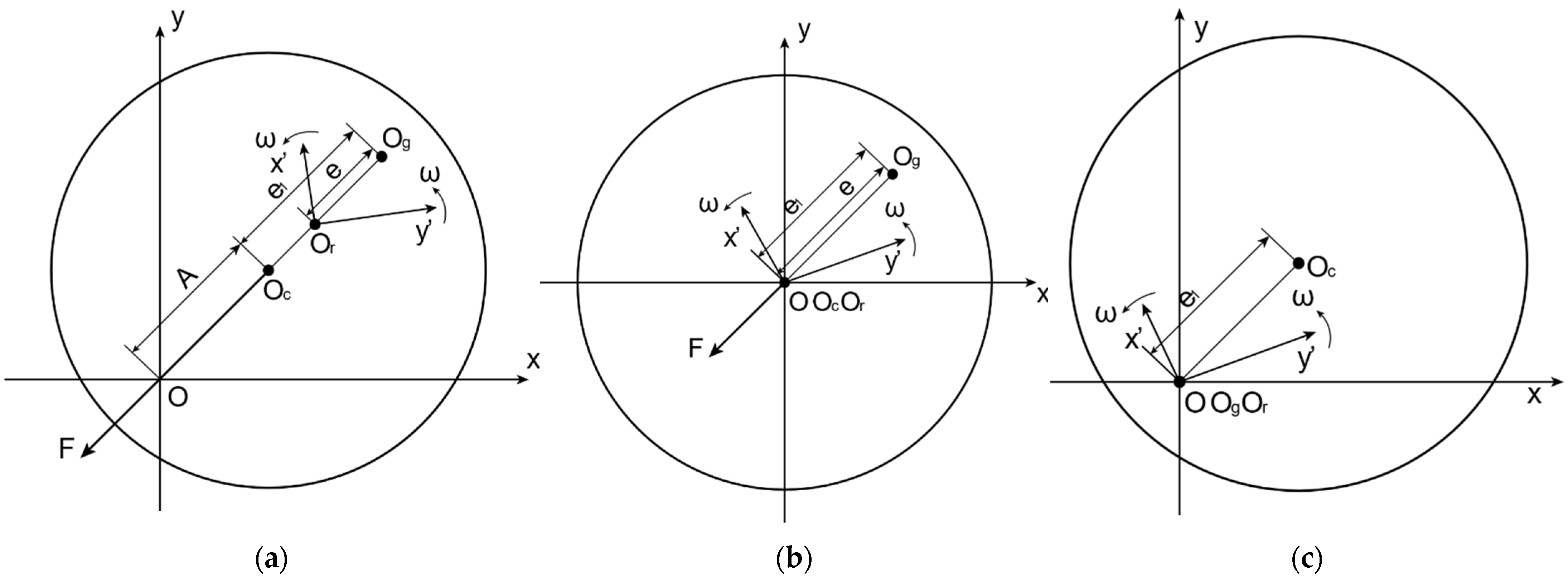
2. Mechanism of Rotor Unbalance of Maglev Motor

Take the rotor centroid section and establish a coordinate system as shown in Figure 1, with the stator center O as the origin. The coordinate axes are two mutually perpendicular electromagnetic force directions x and y , and the stator coordinate system x O y is established. Taking the rotation center O r of the rotor as the origin, the rotor coordinate system x O y is established. When the rotor coordinate system is in the initial state, the coordinate axis direction is consistent with the stator coordinate system. The rotor coordinate system takes the rotor rotation center O r as the origin, and the speed is the rotor speed ω as the rotor rotates synchronously. O c O g ¯ = e 1 is the centroid distance. O r O g ¯ = e is the distance from the rotation axis to the center of mass. Assuming that the rotor section is a standard circle, the coordinates x c , y c of the centroid O c ( x c , y c ) in the stator coordinate system are expressed as the displacement deviation of the rotor in the x-axis direction and the y-axis direction, respectively.
Due to the relatively small support stiffness of the magnetic bearing, when the rotor rotates at high speed, it will rotate around an axis between the geometric center O c and the centroid O g . Because the inertia spindle does not coincide with the rotation shaft, the rotor will produce force vibration [21]. Since the geometric center of the rotor does not coincide with the rotation center, the rotor will produce radial whirl and radial unbalanced displacement vibration [21].
When the rotor rotates around the rotation center and is between the centroid and the centroid, as shown in Figure 1a, the differential equation of motion of the centroid in the x direction is:
m x ¨ c = f u + F x
Thereinto, m is the rotor mass, f u is the unbalanced excitation force generated by the eccentricity of the rotor, and F x is the electromagnetic force generated by the magnetic bearing to control the rotor displacement. There is:
m x ¨ c = m e ω 2 sin ω t + k i i + k x x c
Thereinto, k i and k x are the current stiffness and displacement stiffness of the magnetic bearing. And i is the control current.
It can be seen that the resultant force of the rotor is the resultant force of the inertial force and the electromagnetic force of the magnetic bearing. Because the magnetic bearing control is the displacement deviation control, that is, the rotor inertial force is constrained by the dynamic electromagnetic force, the rotor rotates around its geometric center and x c 0 realizes active control of the rotor. To make the rotor rotate around its geometric center, the minimum displacement unbalance control is realized, that is x c = 0 in Equation (2). At this time, the rotor rotation center and the centroid weight are merged at the stator centroid O, as shown in Figure 1b. It can be seen from the figure that at this time e = e 1 , the unbalanced force reaches the maximum value. From Equation (2), the unbalanced force is completely offset by the kii term.
When the rotor rotates at high speed, due to the existence of mass eccentricity of the rotor, to make the rotor rotate around its geometric center and reduce xc, the inertia force fu of the rotor increases. To meet the requirements of formula (2), the periodic control current i must increase, and the electromagnetic force generated by the periodic control current will be transmitted to the supporting foundation so that the foundation will vibrate. At the same time, when the rotor rotates, the magnetic bearing base is subject to periodic excitation interference, reducing the stability of the system [22].
When the rotor rotates at high speed, because the unbalanced force of the rotor points to the centroid of the rotor, the inertial force makes the rotor rotate automatically close to its centroid, which is the self-centering effect [23]. The displacement deviation control of the magnetic bearing forces the rotor to rotate around its geometric center as much as possible. If the control of the magnetic bearing on the unbalanced vibration is eliminated in some way, the rotor will automatically rotate around its center of inertia. Minimizing both the inertial force and the electromagnetic force, i.e., the minimum inertial force control. As shown in Figure 1c. At this time, the rotor centroid coincides with the rotation center, that is e = 0 , the unbalanced inertia force fu = 0, and the rotor displacement vibration amplitude A = e1. The rotor has only unbalanced displacement, but no unbalanced force. The minimum inertia force control is realized.
From the above analysis, it can be seen that reducing the periodic control current of the magnetic bearing can make the rotor more inclined to its inertial axis rotation, effectively reducing the electromagnetic force and its influence on the supporting foundation.

3. Unbalance Vibration Control of Maglev Motor Based on LMS

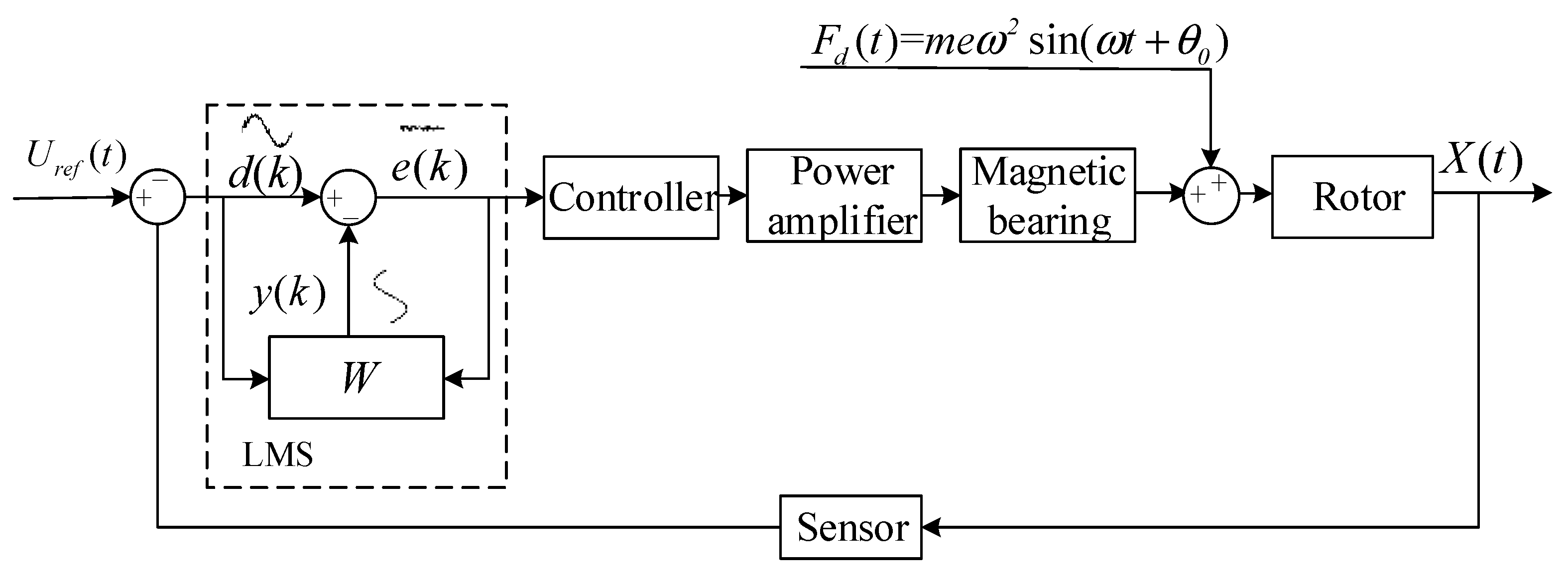
3.1. Unbalance Vibration Control Model of Maglev Motor Rotor

The schematic diagram of the maglev rotor control system with filter compensation is shown in Figure 2. Thereinto, F d ( t ) is the unbalanced force of the rotor, which causes the rotor to produce an unbalanced displacement X ( t ) . Because the actual position of the rotor is inconsistent with the center position, the controller input will produce a periodic deviation signal. The controller produces the corresponding control signal according to the deviation signal. And the periodic electromagnetic force is transmitted to the base reversely, which will also produce the periodic base vibration. From the above analysis, it can be seen that to achieve the rotor unbalanced vibration suppression, the appropriate filter can be selected to filter out the signal of the synchronous frequency as the speed at the input of the controller. The LMS algorithm can effectively filter or extract the sine wave of the specified frequency in the signal, so it is introduced into the rotor control.
The rotor unbalanced displacement signal is sinusoidal in the form of the following:
d ( t ) = A sin ( ω 0 t + φ )
In the formula, A is the amplitude function of the rotor displacement signal concerning time t, ω 0 is the rotor rotation angle frequency, and φ is the displacement phase. Expand Equation (3) as follows:
d ( t ) = A sin φ cos ( ω 0 t ) + A cos φ sin ( ω 0 t )
Let A sin φ = w 1 ( t ) , A cos φ = w 2 ( t ) , then:
d ( t ) = w 1 ( t ) cos ( ω 0 t ) + w 2 ( t ) sin ( ω 0 t )
The discretizations of pair (5) are:
d ( k T ) = w 1 ( k T ) cos ( ω 0 k T ) + w 2 ( k T ) sin ( ω 0 k T )
Thereinto, k 0 , + . T is the sampling period of the digital controller.
From the above analysis, the discrete LMS algorithm shown in Figure 3 can be constructed. In Figure 3, X = sin ( ω 0 k T ) cos ( ω 0 k T ) T is defined as the input vector of the algorithm and W ( k T ) = w 1 ( k T ) w 2 ( k T ) T is the weight vector. d ( k T ) is the expected signal, that is, the rotor displacement signal in the AMB system. y ( k T ) is the algorithm following signal, that is, the signal obtained by real-time amplitude and phase tracking of the signal with the synchronous frequency as the speed in the rotor displacement. e ( k T ) is the algorithm error signal and ω 0 is the filter angular frequency.
The principle of the LMS algorithm is to minimize the objective function by using the gradient random descent method. The specific definition is that the weight vector is updated in a given proportion along the negative direction of the gradient estimation of the error performance surface during iteration. The objective function here is defined as:
δ ( k T ) = d e f i n e E e 2 ( k T )
Among them:
e ( k T ) = d ( k T ) y ( k T ) = d ( k T ) X T ( k T ) W ( k T )
y ( k T ) = y 1 ( k T ) w 1 ( k T ) + y 2 ( k T ) w 2 ( k T )
The joint (7) and (8) expansions are:
δ ( k T ) = E ( d 2 ( k T ) + W T ( k T ) R W ( k T ) 2 H T W ( k T ) )
where R = d e f i n e E X ( k T ) X T ( k T ) , H = d e f i n e E X ( k T ) d ( k T ) . R and H are autocorrelation matrix and cross-correlation matrix functions, respectively. The gradient function of the attainable objective in (10) is:
δ ( k T ) = d e f i n e δ ( k T ) W ( k T ) = 2 H + 2 R W ( k T )
The R and H functions in (11) can be obtained only when the characteristics of the input signal and the desired signal are fully estimated, which leads to an increase in the amount of calculation. The gradient of the objective function can be replaced by the gradient of the mean square error of the e 2 ( k T ) estimation, which is:
e 2 ( k T ) = e T ( k T ) W ( k T ) = 2 e ( k T ) X ( k T )
The iterative update formula of the weight vector can be obtained from Equation (12):
W ( k + 1 ) T = W ( k T ) μ 2 e 2 ( k T ) = W ( k T ) + μ e ( k T ) X ( k T )
In Equation (13), μ is the iteration step length, which satisfies the following condition:
0 < μ < 1 λ max
where λ max is the maximum eigenvalue of R in Equation (14). In practical applications, μ should be as small as possible to meet the requirements of high precision, but too small μ will lead to slow convergence.
From Equations (6), (9) and (13) and Reference [24], the closed-loop transfer function from e k T to y k T is:
G ( z ) = e ( z ) d ( z ) = z 2 2 cos ( 2 π f 0 T s ) z + 1 z 2 + μ 2 cos ( 2 π f 0 T s ) z + ( 1 μ )

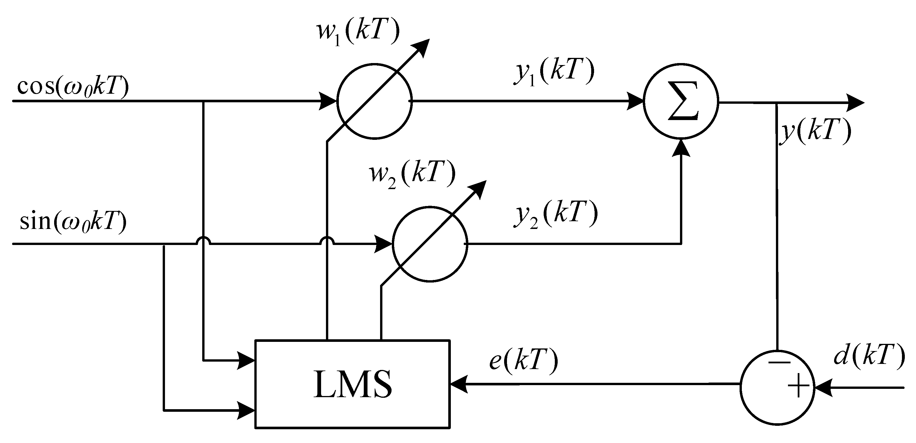
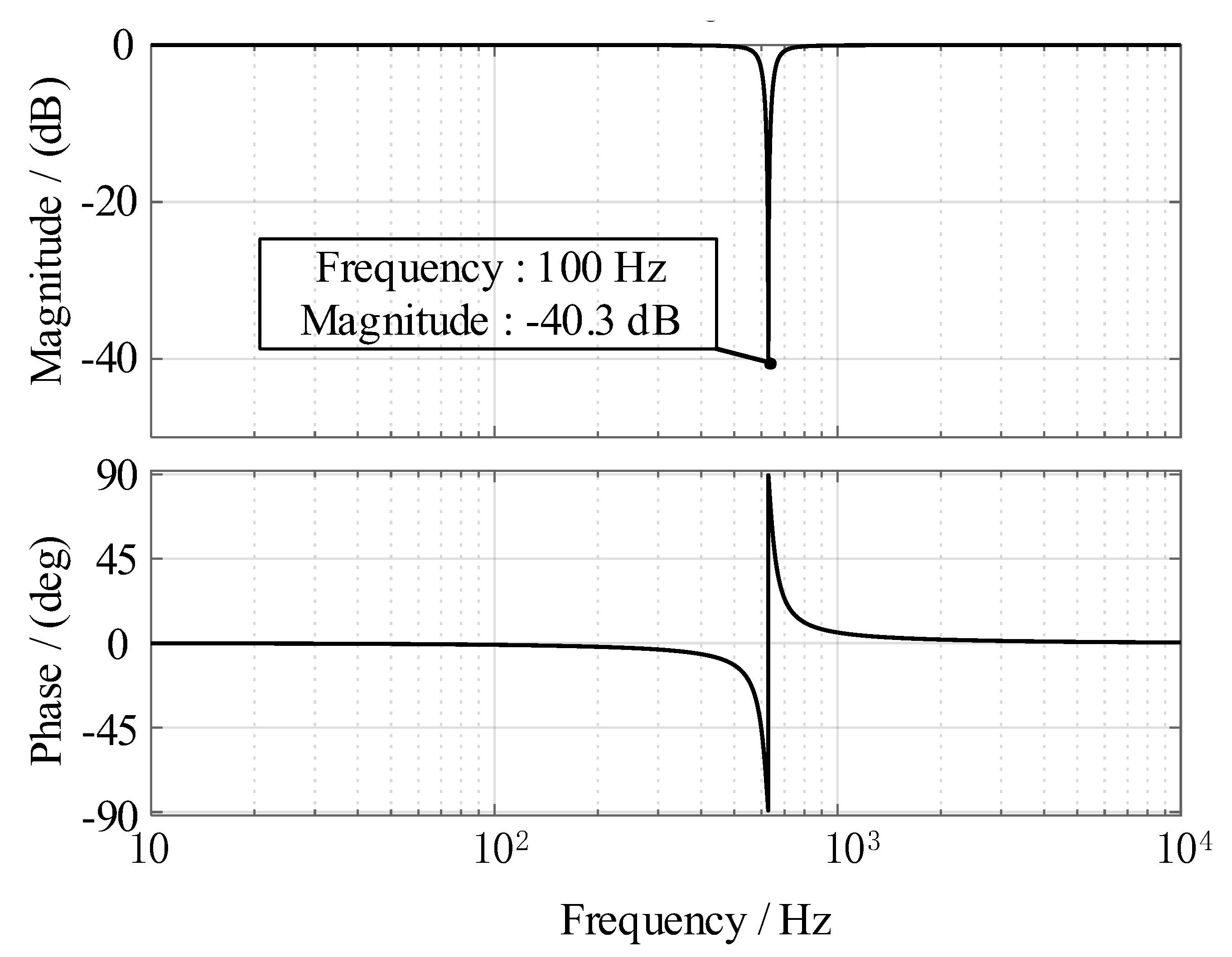
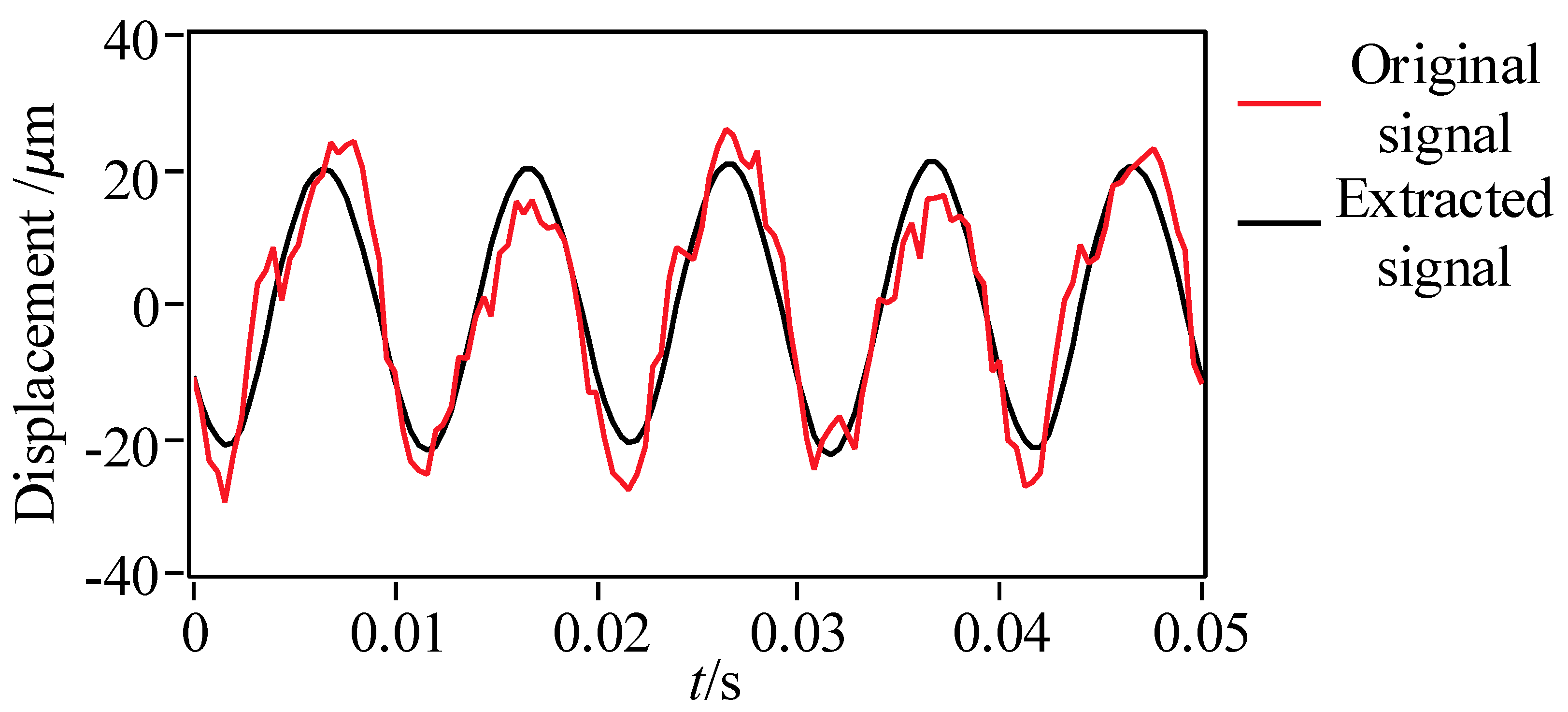
3.2. LMS Filtering Performance Analysis

The amplitude-frequency characteristics, phase-frequency characteristics, and signal extraction effect of Formula (15) are simulated and studied. The sampling period T s = 0.00005   s , the filtering frequency f 0 = 100   Hz , and the step size μ = 0.003 are selected. The transfer function Bode diagram is shown in Figure 4.
According to Figure 4, the output response of the closed-loop transfer function of the LMS algorithm is −40.3 dB at the filtering frequency of 100 Hz, and the LMS algorithm can filter the signal at 100 Hz.
The maglev rotor is set to stably rotate at 6000 r/min. According to the above filter parameter setting, the rotor displacement signal and LMS real-time extraction signal are obtained as shown in Figure 5.

4. Experimental Verification

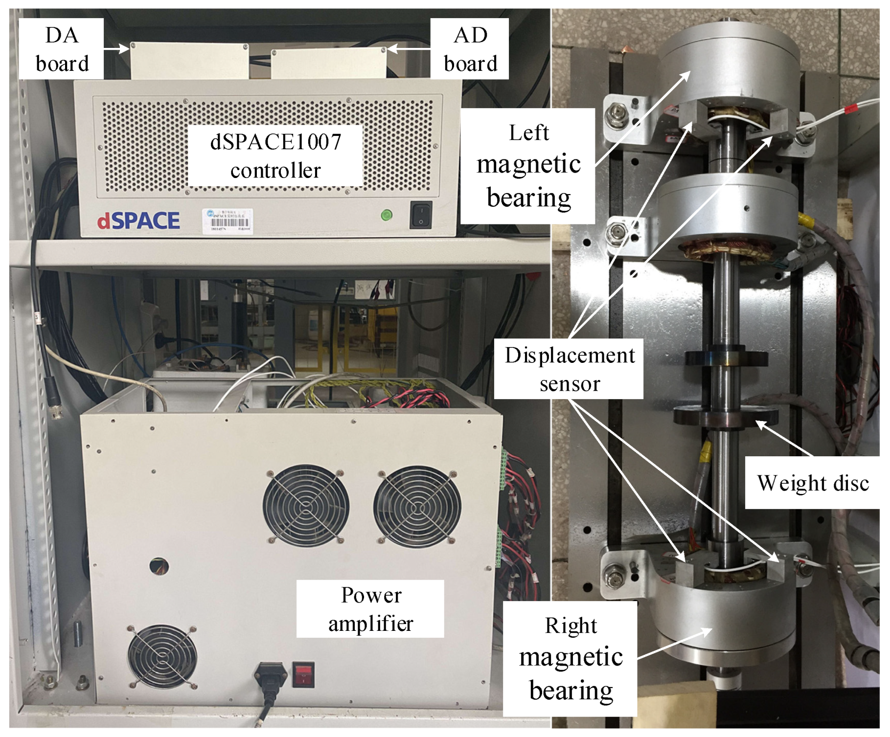
4.1. Experimental Installation

To verify the effectiveness of the algorithm in this paper, an experimental platform of maglev high-speed motor is built, and the rotor online unbalanced compensation experiment is carried out. The experimental platform is shown in Figure 6. The mechanical structure of the experimental platform includes a motor, a rotor, left and right magnetic bearings, a counterweight plate, and so on. The rotor is driven by the right-end motor, and the left and right magnetic bearings support the rotor. The electronic control part of the platform is mainly composed of a dSPACE1007 controller, power amplifier, eddy current displacement sensor, acceleration sensor, data acquisition instrument, and so on. There are two eddy current displacement sensors placed at 90 degrees near the left and right magnetic bearings, which can collect four displacement signals of the rotor. The signal is input into the controller for analysis, and the control voltage is obtained. The control voltage is amplified by the power amplifier to the control current to supply the magnetic bearing to realize the active control of the rotor. At the same time, two acceleration sensors are installed on the supporting base to detect the vibration transmitted by the magnetic bearing to the supporting foundation.

4.2. Experimental Result

Firstly, the digital PID control algorithm is used to control the stable suspension of the rotor. The controller control period is Ts = 0.00004 s, and then the LMS algorithm is added to suppress the unbalanced vibration. Figure 7 shows the displacement and current diagram in the x direction of the left end when the rotor is statically suspended. The motor speed is set to 6000 r/min. The real-time displacement of the rotor is measured by the eddy current displacement sensor, and the output current of the controller is collected. Figure 8 shows the changes in rotor displacement and current when the LMS algorithm is used to compensate. The comparison of the time domain and frequency domain before and after LMS compensation is shown in Figure 9 and Figure 10.
It can be seen from Figure 9 and Figure 10 that before compensation, due to the unbalanced vibration of the rotor, to compensate for the vibration, the controller outputs the control current in real-time. From the spectrum diagram, it can be seen that the main frequency components in the rotor displacement and the magnetic bearing control current are in synchronous frequency with the speed. That is, the main factor affecting the rotor vibration is unbalanced vibration, and the main component of the magnetic bearing control output is also the unbalanced control current with the synchronous frequency. After compensation, the co-frequency control current of the rotor is reduced by 92%, close to 0. And the co-frequency vibration displacement of the rotor is reduced by 87%, reduced to 3 μm. This is due to the reduction of the co-frequency control current, which makes the rotor rotate closer to its inertial spindle. The unbalanced inertia force is reduced, and the rotor amplitude is reduced. At this time, the rotor unbalance force is the smallest, but there is a small unbalance displacement whose amplitude is close to the distance between the rotor centroid and the centroid.
It can be seen from Figure 10 that the vibration and control current with the synchronous frequency as rotational speed are reduced after LMS compensation, and the main component of the vibration and control current is its frequency doubling component. To better control the vibration of the maglev rotor and reduce unbalance components in the control current of the magnetic bearing. In this paper, a harmonic control algorithm based on LMS is proposed to compensate for the harmonic vibration while compensating for the synchronous frequency vibration of the speed. In the control algorithm shown in Figure 2, based on compensating the fundamental frequency vibration of the rotor, the main harmonic vibration component frequency (200 Hz here) is used as the input frequency. The harmonic vibration is also filtered and compensated according to the control method shown in Figure 2. The compensation result is shown in Figure 11. From Figure 11, it can be seen that after further harmonic compensation, the harmonic vibration amplitude of the rotor does not change much, the harmonic control current is reduced by 64% and the amplitude of the synchronous frequency of the speed and its harmonic components in the current spectrum is reduced close to 0. There is only a maximum peak of 0.36 A at 0 Hz, which is a constant current provided by the magnetic bearing to overcome the rotor gravity and keep the rotor in a stable suspension state.
The data with a time of 1 s were randomly taken, and the peak-to-peak mean was obtained. The results are shown in Table 1. Compared with the uncompensated, the peak-to-peak average value of the rotor displacement vibration is reduced by 67.4% and the peak-to-peak average value of the control current is reduced by 31% after using the fundamental frequency and harmonic vibration control algorithm based on LMS in this paper. Compared with the displacement and control current in static suspension, they only increased by 32.6% and 6.5%, respectively.
Through the acceleration sensor installed on the base, and we measured acceleration signals of rotor static suspension before and after LMS control. Figure 12 shows the base acceleration spectrum when the rotor is statically suspended. Figure 13 shows the base acceleration spectrum of the before and after LMS compensation.
From Figure 12, it can be seen that when the rotor is statically suspended, the base mainly has a vibration of about 400 Hz, which is the working frequency of the magnetic bearing. The frequency is mainly determined by the control parameters and the output characteristics of the hardware equipment such as the power amplifier, which does not belong to the research scope of this paper. The following mainly studies the base vibration caused by rotor imbalance.
It can be seen from Figure 13a that before LMS compensation, the maximum peak of the base acceleration signal is located at the synchronous frequency of 100 Hz. Since the magnetic bearing has no mechanical contact with the rotor, the base vibration is mainly generated by the control reaction force of the magnetic bearing to the rotor, which is the control electromagnetic force generated by the active suppression of the rotor unbalanced vibration by the magnetic bearing. Figure 13b is the base acceleration signal after LMS compensation. After the LMS algorithm compensation in this paper, the co-frequency vibration amplitude of the base speed is attenuated by 80.4%. Figure 14 shows the time-frequency spectrum of the base acceleration. It can be seen that before the compensation, the base acceleration has an obvious 100 Hz co-frequency component. When the compensation starts, the frequency component decreases rapidly and maintains a low vibration level. When the compensation stops, the 100 Hz component of the base acceleration is restored to the vibration level before compensation.

5. Conclusions

The unbalance vibration suppression of maglev high-speed motor based on the Least-Mean-Square is investigated in this paper. The Least-Mean-Square control method is adopted to actively control the vibrations caused by the unbalanced excitation vibration. The numerical simulation and experimental research are carried out. From the present investigations, the following key observations can be obtained:
(1)
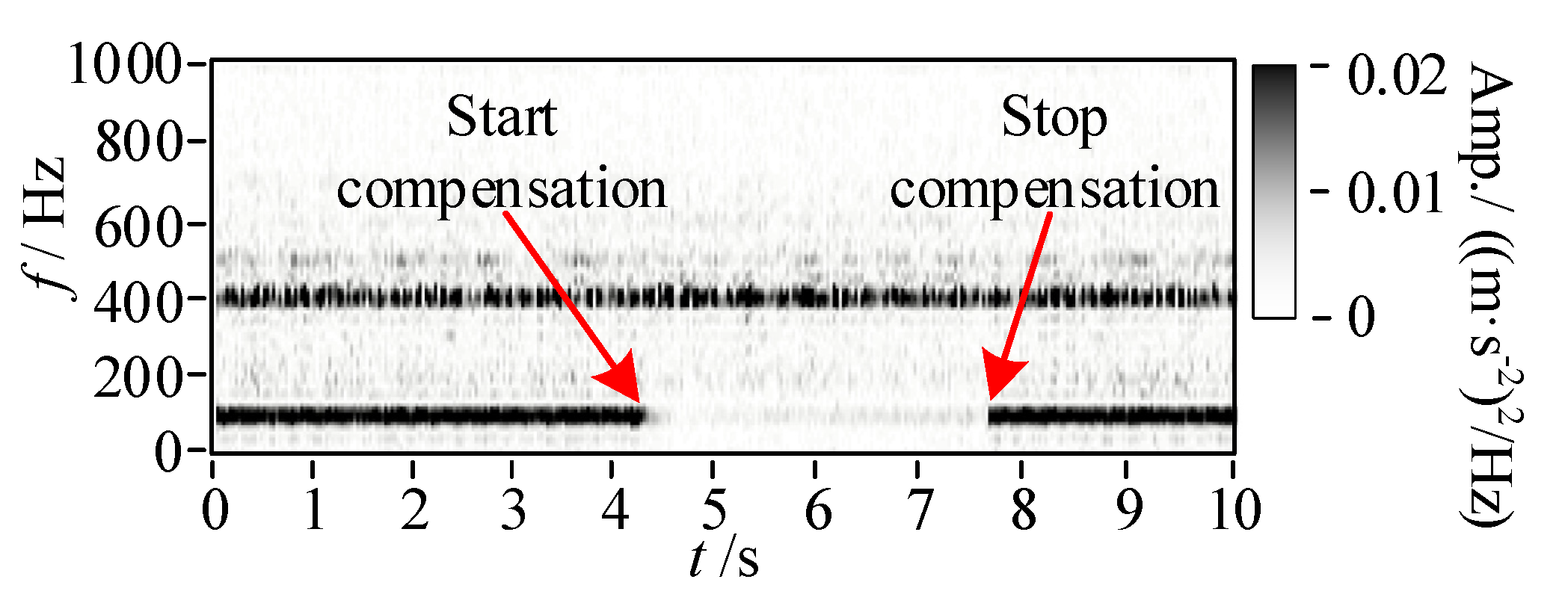
The LMS algorithm can effectively filter out the sine wave with a specified frequency in the signal, which is introduced into the unbalance compensation process of the maglev rotor to realize the unbalance vibration suppression of the maglev rotor.
(2)
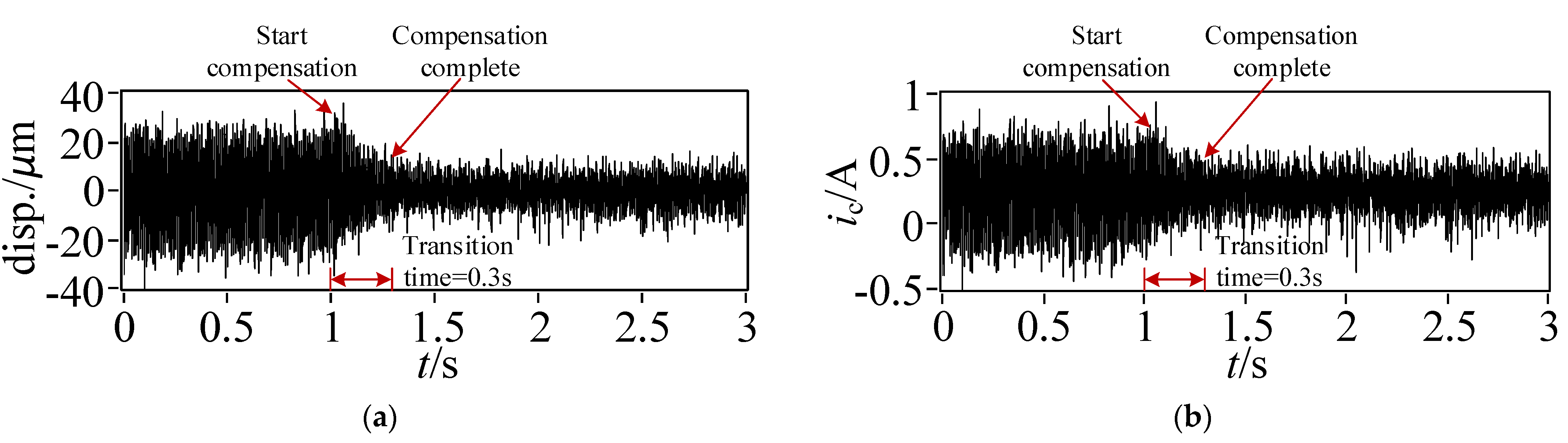
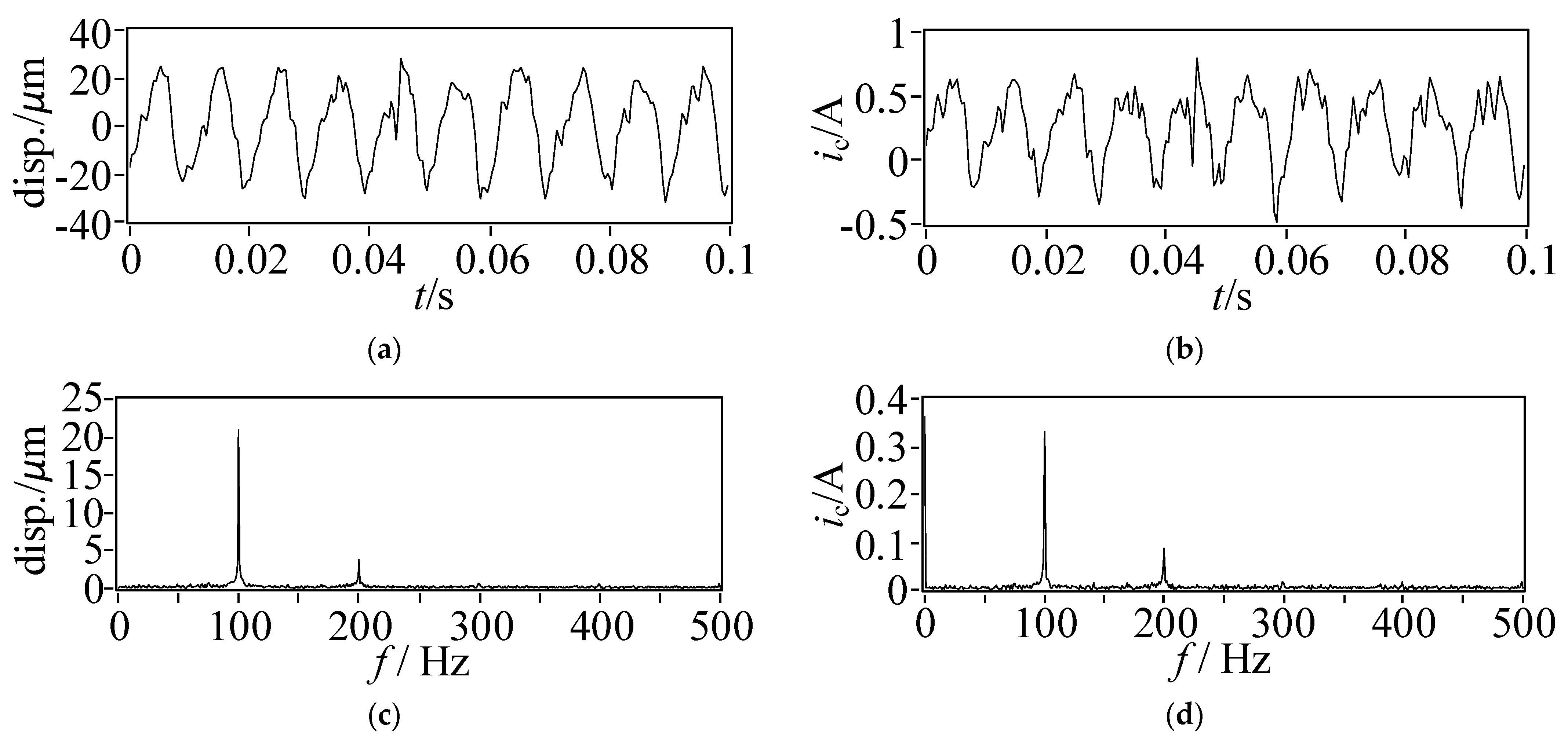
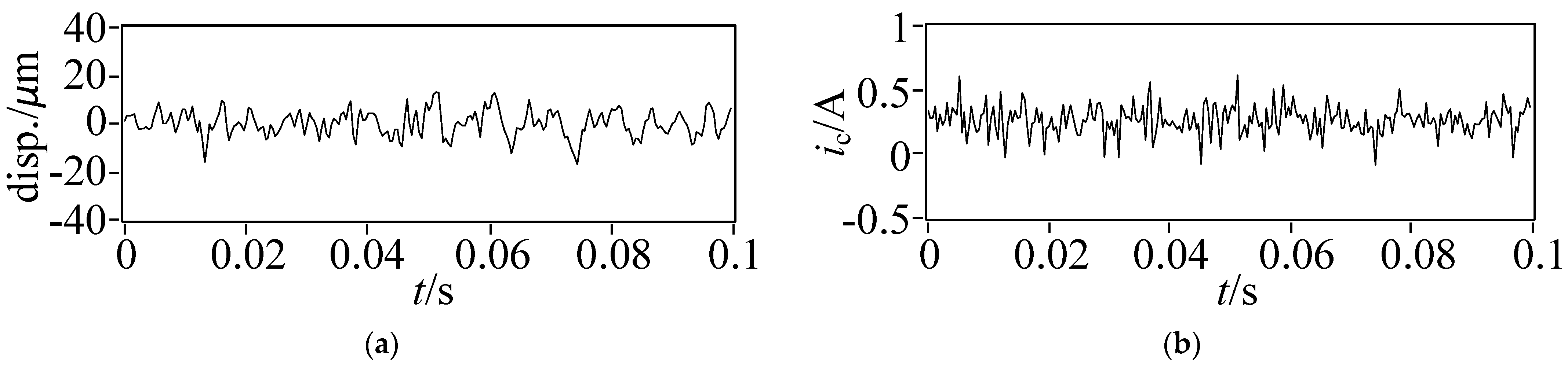
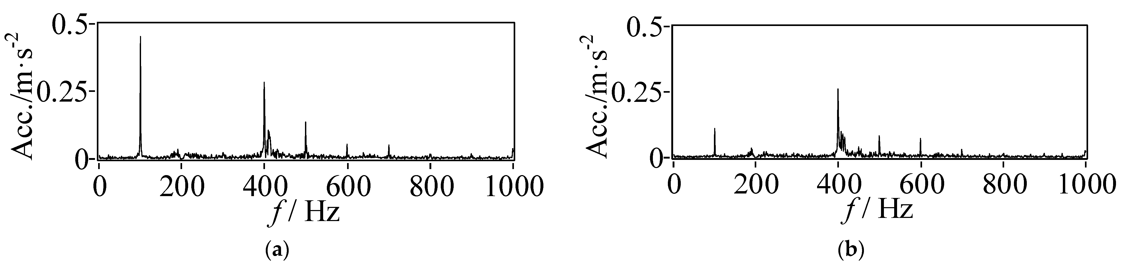
Using the LMS algorithm control in this paper, after filtering the unbalanced signal of the synchronous frequency of 100 Hz, the synchronous frequency displacement of the maglev rotor and the synchronous frequency control current of the magnetic bearing is reduced by 87% and 92%, respectively. Further filtering the harmonic signal of the maglev rotor can effectively reduce the harmonic control current of the magnetic bearing. Further reduction of unbalanced control of rotors by magnetic bearings to better realize the unbalanced vibration control of the rotor.
(3)
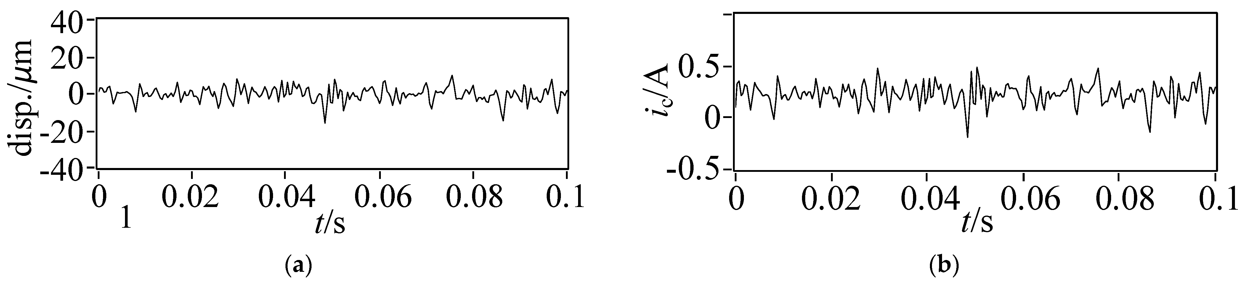
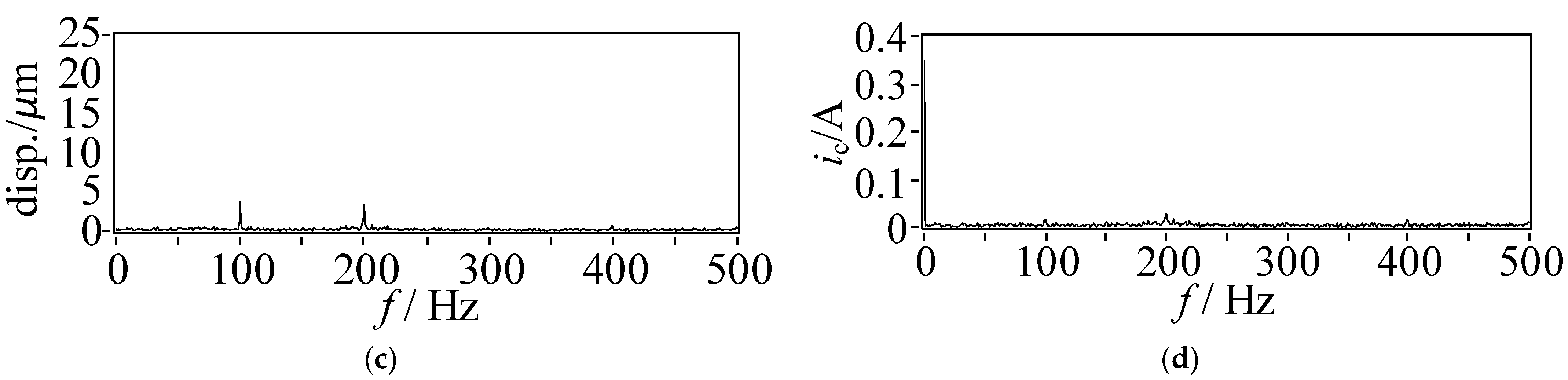
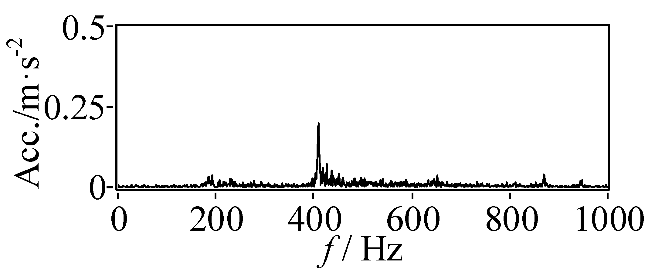
The final compensation results show that the peak-to-peak mean value of rotor displacement decreases by 67.4% and the peak-to-peak mean value of control current decreases by 31% after using the LMS-based fundamental frequency and harmonic vibration control algorithm. Compared with the displacement and control current in static suspension, they only increase by 32.6% and 6.5%, respectively. At the same time, the vibration amplitude of the synchronous frequency with the base speed is attenuated by 80.4%.
The experimental results show that the algorithm can realize the rotor’s unbalanced vibration control, make the rotor rotate around its inertial axis, reduce the rotor’s unbalanced displacement vibration and forced vibration, reduce the control current of the magnetic bearing, reduce the power consumption of the control system, and decrease the vibration of the magnetic bearing to the supporting foundation.

Author Contributions

H.W.: conception of the study, propose theory and method, supervisor; M.Y.: literature search, figures, and data collection; C.S.: manuscript preparation and writing; N.W.: data interpretation and analysis. All authors have read and agreed to the published version of the manuscript.

Funding

This research was funded by Shenzhen Science and Technology Plan Project (Grant No. JCYJ20190809150603586) and National Natural Science Foundation (Grant No. 51975427).

Institutional Review Board Statement

Not applicable.

Informed Consent Statement

Not applicable.

Data Availability Statement

Not applicable.

Conflicts of Interest

The authors declare no conflict of interest.

References

  1. Sun, F.; Jin, J.J.; Oka, K. Permanent Magnetic Suspension System-Principle, Model, Simulation and Experiment; Beijing Science Press: Beijing, China, 2018. [Google Scholar]
  2. Zhao, C.; Sun, F.; Jin, J.J.; Tang, H.J.; Xu, F.; Li, Q.; Oka, K. Analysis of quasi-zero power characteristic for a permanent magnetic levitation system with a variable flux path control mechanism. IEEE-ASME Trans. Mechatron. 2021, 26, 1416–1420. [Google Scholar] [CrossRef]
  3. Zhou, R.; Yan, M.Y.; Sun, F.; Jin, J.; Li, Q.; Xu, F.; Zhang, M.; Zhang, X.; Nakano, K. Experimental validations of a magnetic energy-harvesting suspension and its potential application for self-powered sensing. Energy 2022, 239, 122205. [Google Scholar] [CrossRef]
  4. Xu, Y.; Wu, H.; Guan, X. Unbalance Suppression for AMB Rotor System Using APF-SRF Algorithm. Shock. Vib. 2020, 1–10. [Google Scholar] [CrossRef]
  5. Mohamed, M.E.; Bonello, P. The efficient inclusion of rotation-induced inertia effects in a shaft-blisk assembly model using zero-speed modes. J. Sound Vib. 2020, 479, 115357. [Google Scholar] [CrossRef]
  6. Herzog, R.; Buhler, P.; Gahler, C.; Larsonneur, R. Unbalance compensation using generalized notch filters in the multivariable feedback of magnetic bearings. IEEE Trans. Control. Syst. Technol. 1996, 4, 580–586. [Google Scholar] [CrossRef]
  7. Lum, K.Y.; Coppola, V.T.; Bernstein, D.S. Adaptive auto-centering control for an active magnetic bearing supporting a rotor with unknown mass imbalance. IEEE Trans. Control. Syst. Technol. 1996, 4, 587–597. [Google Scholar]
  8. Setiawan, J.; Mukherjee, R.; Maslen, E. Synchronous Disturbance Compensation in Active Magnetic Bearings Using Bias Current Excitation. In Proceedings of the IEEE/ASME International Conference on Advanced Intelligent Mechatronics, Como, Italy, 8–12 July 2001; pp. 707–712. [Google Scholar]
  9. Matras, A.; Flowers, G.; Fuentes, R.; Balas, M.; Fausz, J. Suppression of persistent rotor vibrations using adaptive techniques. J. Vib. Acoust. 2003, 128, 682–689. [Google Scholar] [CrossRef]
  10. Chiacchiarini, H.; Mandolesi, P. Unbalance compensation for active magnetic bearings using ILC. In Proceedings of the IEEE International Conference on Control Applications, Mexico City, Mexico, 7 September 2001; pp. 58–63. [Google Scholar]
  11. Betschon, F.; Knospe, C.R. Reducing magnetic bearing currents via gain scheduled adaptive control. IEEE/ASME Trans. Mechatron. 2001, 6, 437–443. [Google Scholar] [CrossRef]
  12. Zheng, S.; Feng, R. Feedforward compensation control of rotor imbalance for high-speed magnetically suspended centrifugal compressors using a novel adaptive notch filter. J. Sound Vib. 2016, 366, 1–14. [Google Scholar] [CrossRef]
  13. Nonami, K.; Qifu, F.; Ueyama, H. Unbalance vibration control of magnetic bearing systems using an adaptive algorithm with disturbance frequency estimation. JSME Int. J. 2008, 41, 220–226. [Google Scholar] [CrossRef] [Green Version]
  14. Rundell, A.; Drakunov, S.; Decarlo, R. A sliding mode observer and controller for stabilization of rotational motion of a vertical shaft magnetic bearing. IEEE Trans. Control. Syst. Technol. 1996, 4, 598–608. [Google Scholar] [CrossRef] [PubMed]
  15. Mohamed, A.; Ilene, B. Imbalance compensation and automatic balancing in magnetic bearing systems using the Q-parameterization theory. In Proceedings of the American Control Conference, Baltimore, MD, USA, 30 June–2 July 1994; pp. 2952–2957. [Google Scholar]
  16. Han, B.; Cui, H.; Tang, E. Vibration suppression of magnetic bearing based on sliding mode disturbance observer. Opt. Precis. Eng. 2012, 20, 563–570. [Google Scholar]
  17. Zhang, Y.; Zhou, J.; Han, X.; Zhou, Y. Adaptive odd repetitive control for magnetically suspended rotor harmonic currents suppression. J. Vib. Control. 2022, 89, 510–526. [Google Scholar] [CrossRef]
  18. Xu, Y.; Jiang, Q.; Yang, K.; Zhou, J.; Guo, Q. A novel ultra-high-resolution inclination sensor based on diamagnetic levitation. Sens. Actuators A Phys. 2022, 343, 113686. [Google Scholar] [CrossRef]
  19. Ashkezari-Toussi, S.; Sabzevari, V.R. Early arrhythmia prediction based on Hurst index and ECG prediction using robust LMS adaptive filter. Signal Image Video Process. 2021, 15, 1813–1820. [Google Scholar] [CrossRef]
  20. Nishikawa, K. The LMS-Type Adaptive Filter Based on the Gaussian Model for Controlling the Variances of Coefficients. IEICE Trans. Fundam. Electron. Commun. Comput. Sci. 2020, E103.A, 1494–1502. [Google Scholar] [CrossRef]
  21. Zhang, H.; JLiu Zhu, R.; Chen, H.; Yuan, H. Nonlinear adaptive harmonics vibration control for an active magnetic bearing system with rotor unbalance and sensor runout. IEEE Sens. J. 2021, 21, 12245–12254. [Google Scholar] [CrossRef]
  22. Soni, T.; Dutt, J.K.; Das, A.S. Parametric Stability Analysis of Active Magnetic Bearing Supported Rotor System With a Novel Control Law Subject to Periodic Base Motion. IEEE Trans. Ind. Electron. 2020, 67, 1160–1170. [Google Scholar] [CrossRef]
  23. Wang, M.; Han, Q.; Wen, B.; Zhang, H.; Guan, T. Modal characteristics and unbalanced responses of fan rotor system with flexible support structures in aero-engine. Proc. Inst. Mech. Eng. Part G J. Aerosp. Eng. 2017, 231, 1686–1705. [Google Scholar] [CrossRef]
  24. Gao, H.; Song, L. Modified LMS algorithm applied to maglev flywheel’s vibration compensation problem. Int. J. Appl. Electromagn. Mech. 2017, 53, 359–369. [Google Scholar] [CrossRef]
Figure 1. Three cases of rotor unbalance. (a) When the rotor rotation center is between the centroid centroids; (b) Rotor rotation center at the centroid; (c) When rotor rotation center is in the center of mass.
Actuators 11 00348 g001
Figure 2. Principle of unbalanced vibration suppression control algorithm for maglev rotor.
Actuators 11 00348 g002
Figure 3. LMS adaptive filtering principle.
Actuators 11 00348 g003
Figure 4. Standard LMS algorithm closed-loop transfer function bode diagram.
Actuators 11 00348 g004
Figure 5. LMS algorithm real-time extraction effect.
Actuators 11 00348 g005
Figure 6. Experimental platform.
Actuators 11 00348 g006
Figure 7. Rotor static suspension displacement and control current. (a) displacement diagram; (b) current graph.
Actuators 11 00348 g007
Figure 8. LMS compensation process. (a) displacement diagram; (b) current graph.
Actuators 11 00348 g008
Figure 9. The amplitude-frequency diagram of displacement and current before rotor LMS compensation. (a) Time domain spectrum of displacement; (b) Time domain spectrum of current; (c) Frequency spectrum of displacement; (d) Frequency spectrum of current.
Actuators 11 00348 g009
Figure 10. The amplitude-frequency diagram of displacement and current after rotor LMS compensation. (a) Time domain spectrum of displacement; (b) Time domain spectrum of current; (c) Frequency spectrum of displacement; (d) Frequency spectrum of current.
Actuators 11 00348 g010
Figure 11. The amplitude-frequency diagram of displacement and current after rotor LMS harmonic compensation. (a) Time domain spectrum of displacement; (b) Time domain spectrum of current; (c) Frequency spectrum of displacement; (d) Frequency spectrum of current.
Actuators 11 00348 g011aActuators 11 00348 g011b
Figure 12. Base acceleration spectrum of the rotor in static suspension.
Actuators 11 00348 g012
Figure 13. Base acceleration spectrum before and after rotor LMS compensation. (a) Compensation for acceleration spectrum of the front base; (b) Acceleration spectrum of the base after compensation.
Actuators 11 00348 g013
Figure 14. Time-frequency spectrum of base acceleration.
Actuators 11 00348 g014
Table 1. Rotor Displacement and Current Peak-Peak Mean Value.
Peak-Peak Mean Value
Displacement (μm)Current (A)
static levitation9.320.46
100 Hz rotation, no compensation38.770.71
100 Hz rotation, after compensation12.630.49
Publisher’s Note: MDPI stays neutral with regard to jurisdictional claims in published maps and institutional affiliations.

