Article

Analysis of Trajectory Tracking Characteristics of a Magnetically Driven Oil-Free Scroll Compressor

1
School of Mechanical Engineering, Shenyang University of Technology, Shenyang 110801, China
2
School of Systems Engineering, Kochi University of Technology, Kochi 782-8502, Japan
*
Author to whom correspondence should be addressed.
Actuators 2022, 11(11), 312; https://doi.org/10.3390/act11110312
Submission received: 9 September 2022 / Revised: 25 October 2022 / Accepted: 25 October 2022 / Published: 27 October 2022
(This article belongs to the Special Issue Advanced Theory and Application of Magnetic Actuators)

Abstract

:
The conventional scroll compressor cannot run oil-free because of wear and tear and lubrication problems during operation due to some parts, such as anti-rotation devices. The magnetic drive oil-free scroll compressor (MDOFSC) uses a contactless drive method to avoid this drawback. In order to solve the swing problem of the orbiting scroll during the operation of the MDOFSC, decentralized control and centralized control are used to study the trajectory tracking characteristics. Firstly, the structure and working principle of the MDOFSC are introduced, and the system’s magnetic circuit and differential control principle are analyzed. Then, the dynamic model of the MDOFSC under the condition of non-compressed gas is established, and the coordinate matrix decoupling method is used to analyze the relationship between the degree of freedom of the system and the measurement distance of the displacement sensor. Finally, the system is simulated and experimentally studied under centralized PID control, and the experimental comparison study between decentralized control and centralized control is conducted. The results show that centralized control dramatically improves the trajectory control ability of the system.

1. Introduction

Scroll compressors have many unique advantages, such as a simple structure, low noise, high efficiency, and good reliability. As the application of scroll compressors extends to medicine, food, and other fields requiring clean compressed gas, developing an oil-free scroll compressor has essential practical significance [1,2].
Li proposed a sealing mechanism model to achieve sealing of scroll tooth axial clearance by installing self-lubricating material sealing strips and springs in the sealing groove opened on the tooth end face [3]. In existing oil-free scroll compressors, the first type uses self-lubricating bearings instead of oil-lubricated bearings; the second type coats a layer of self-lubricating material on the surface of the anti-rotation device and the contact surface of the moving and stationary scroll. Although the two methods achieve the goal of being oil-free, there are some problems with friction and heating. Sun proposed an oil-free scroll compressor with a solenoid instead of an anti-rotation device and no wearing parts. Only modeling and simulation were performed in the article, and no experimental study was conducted [4,5]. Magnetic levitation technology, with its fast response, high accuracy, and clean and pollution-free features, provides new solutions for several industries and has been widely used under the intensive research of many scholars, with typical applications such as magnetic levitation bearings [6,7], magnetic levitation trains [8], and magnetic levitation planar motors [9]. Zhao proposed a new magnetic levitation system with two rotating magnets that can achieve a zero-power horizontal levitation state under eccentric loading [10]. Soni investigated the dynamical behavior and stability of energy-efficient electromagnetic levitation with time-lag rotors.
The control formulas were transformed to the frequency domain, the time lag values of the feedback signals were modeled using the Pade approximation, and stability analysis was performed by analyzing the system poles [11]. Zhang X provided a six-degree-of-freedom levitation platform. This study manipulated the levitation carrier completely without a tether in a large area and calculated the wrench matrix quickly and accurately using the magnetic node method and the Lorentz force law [12]. Graphene levitation and magnetic field orientation control were studied in the literature [13]. Torques induced by antimagnetic forces in all three spatial directions were used to predict stability conditions for millimeter-scale graphite plates of different shapes. Article [14] introduces the design principle, and the initial model of radial-axial magnetic bearing proposes a multi-objective optimization method of bearing and provides the analytical expression of the equivalent magnetic circuit, verified by finite element analysis and experiments. For the problem that the magnetic saturation of the core reduces the maximum output force of the magnetic bearing, an improved core design criterion for the cross-polar magnetic bearings is proposed in the paper [15]. The three-dimensional finite element method and experiments also successfully verified the optimization method. The method can provide a reference for designing and selecting active magnetic bearings. In order to predict the performance and guide the design of permanent magnet-biased three-degree-of-freedom magnetic levitation bearings, Yun proposed an accurate analytical model including the eddy current effect and leakage effect. The stiffness was investigated by static and transient finite element methods (fem). Finally, a prototype was designed and fabricated, and the validity of the analysis was verified using the finite element results and experimental results [16]. In the articles [17], the dynamics of a six-degree-of-freedom bearingless linear motor system were modeled using a set-sum modeling approach. The validity of the established model was verified by comparing the time-domain simulation results with the experimental results.
The model can be applied to time-domain simulation, real-time control system development, and various system analyses. The article [18] proposes the integration of magnetic bearings into a tubular linear actuator (TLA), resulting in a new self-bearing (bearingless) TLA. The system is derived from a standard TLA by changing its stator geometry. The working principle is illustrated using the finite element method, and critical design aspects are investigated. Sun proposes a three-degree-of-freedom permanent magnetic levitation platform for cleanroom conveying systems, which is supported by four magnetic poles and uses a variable flux path mechanism. Based on the analysis of the dynamics, the magnetic levitation platform’s mathematical model and state space are established. A double closed-loop controller for stable levitation and motion control is designed, and the control system is decoupled using a coordinate transformation matrix. Finally, simulations and experiments were conducted to achieve stable levitation and three-degree-of-freedom motion control with remarkable positioning accuracy [19,20,21].
Magnetic levitation has been widely used in the biomedical industry due to its advantages of cleanliness and non-contact. Ke proposed a planar Litz coil sandwiched between two ferrite substrates optimized design method that wirelessly powers a novel mechanical artificial anal sphincter system for treating severe fecal incontinence [22]. Zhou designed a novel implantable puborectal-like artificial anal sphincter (PAAS) that replicates rectal perception with a low risk of ischemic necrosis. A pressure sensor embedded in the PAAS was used to determine the relationship between the stool mass and pressure and to develop a stool mass estimation model based on in vitro studies [23]. Articles [24,25,26] applied magnetic levitation technology to studies on artificial hearts to optimize the improvement of magnetic pumps. Forrai investigated the system identification and control of a nonlinear electromagnetic actuator that could be used in an artificial heart actuator [27]. Haisler described a 3D culture method, the magnetic levitation method (MLM), in which cells are combined with magnetic nanoparticle assemblies overnight to provide them with magnetic properties. When resuspended in the medium, an external magnetic field causes the cells to levitate and concentrate at the gas–liquid interface, where they aggregate to form larger 3D cultures [28]. Parfenov proposed the rapid creation of 3D scaffolds using the magnetic levitation of calcium phosphate particles. Label-free suspension assembly was achieved in the presence of gadolinium salts by using a custom-designed magnetic system that allowed the suspension of calcium phosphate particles. The chemical conversion of tricalcium phosphate to octacalcium phosphate under magnetic levitation conditions in a non-uniform magnetic field was also demonstrated [29]. Yaman developed a magnetization-rate-based protein detection scheme using a low-cost, miniaturized magnetic levitation device consisting of two opposing magnets to generate a magnetic field gradient, a glass capillary channel to retain the sample, and two lateral mirrors to monitor the interior of the channel. The method involves using polymeric microspheres as a mobile analysis surface and magnetic nanoparticles as markers. The assay is achieved by trapping the target protein in the polymer microspheres [30].
The MDOFSC proposed in this paper has the advantages of no oil and stable operation at a low-pressure ratio. It can be used in the medical environment to provide oxygen for patients and improve cardiac extracorporeal membrane oxygenation. Based on the electromagnetic drive principle, this paper proposes the MDOFSC, the relationship between the nonlinear magnetic model and the working air-gap length is analyzed, and the decoupling control model of MDOFSC is established by applying the coordinate transformation strategy. With the goal of trajectory control, a centralized controller was designed and experimentally verified.

2. Description of the System

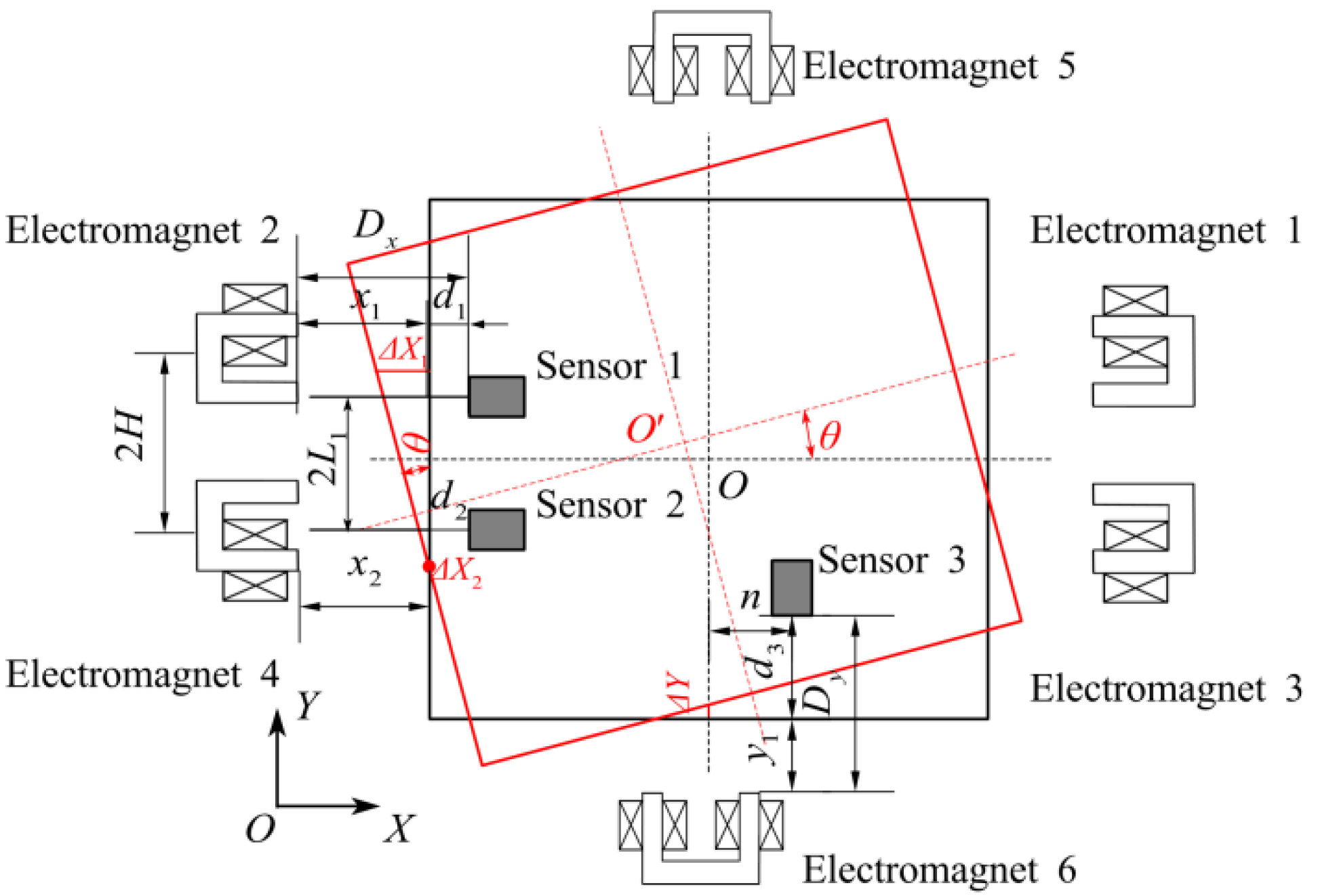
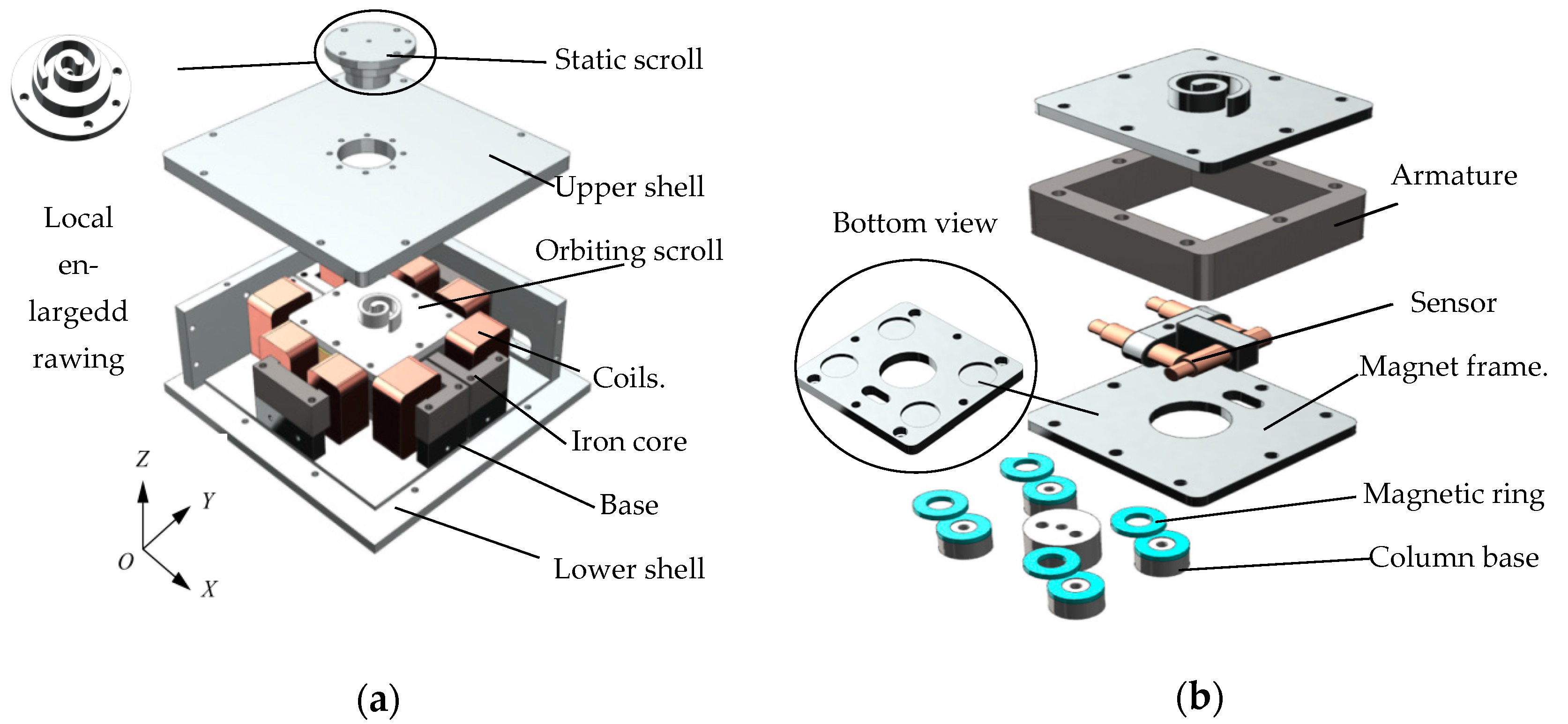
2.1. Structure and Principle

The structure of the MDOFSC is shown in Figure 1, which is mainly composed of orbiting scroll, static scroll, electromagnet, armature, magnetic ring, sensor, etc. The working principle of the MDOFSC is that three groups of electromagnets attract the armature and orbital scrolls to achieve orbital motion and compress the gas. In order to make the MDOFSC work with a specific stiffness, each group of electromagnets is controlled differentially. The MDOFSC is equipped with six electromagnets inside. The open-loop electromagnetic drive system is unstable, and difficult to control the running trajectory. In order to realize the closed-loop control of the running track of MDOFSC, each group of electromagnetic units is executed by a servo system composed of a controller, a sensor, and a power amplifier. The sensor in the Y direction measures the position of the armature and the two sensors in the X direction measure the position and rotation angle of the armature. Through real-time detection and control, the distance between the two X directions is kept straight and equal to ensure the translational movement of the orbiting scroll, which replaces the anti-rotation mechanism, reducing friction and realizing oil-free operation. As shown in Figure 1b, four sets of permanent magnet rings are mounted in four bracket recesses, forming symmetrically distributed mutually exclusive upper and lower sections to support the suspension of the orbiting scroll.

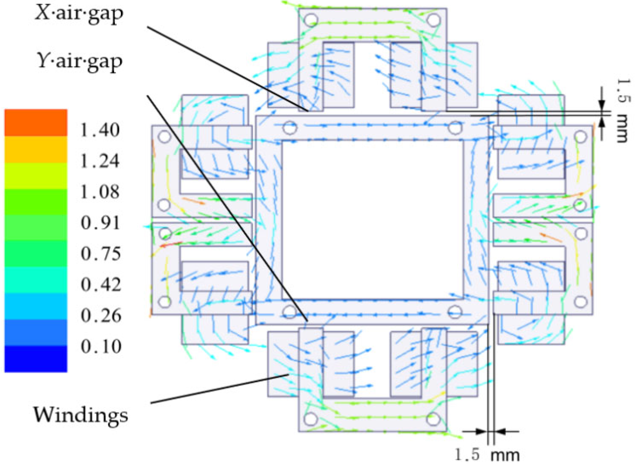
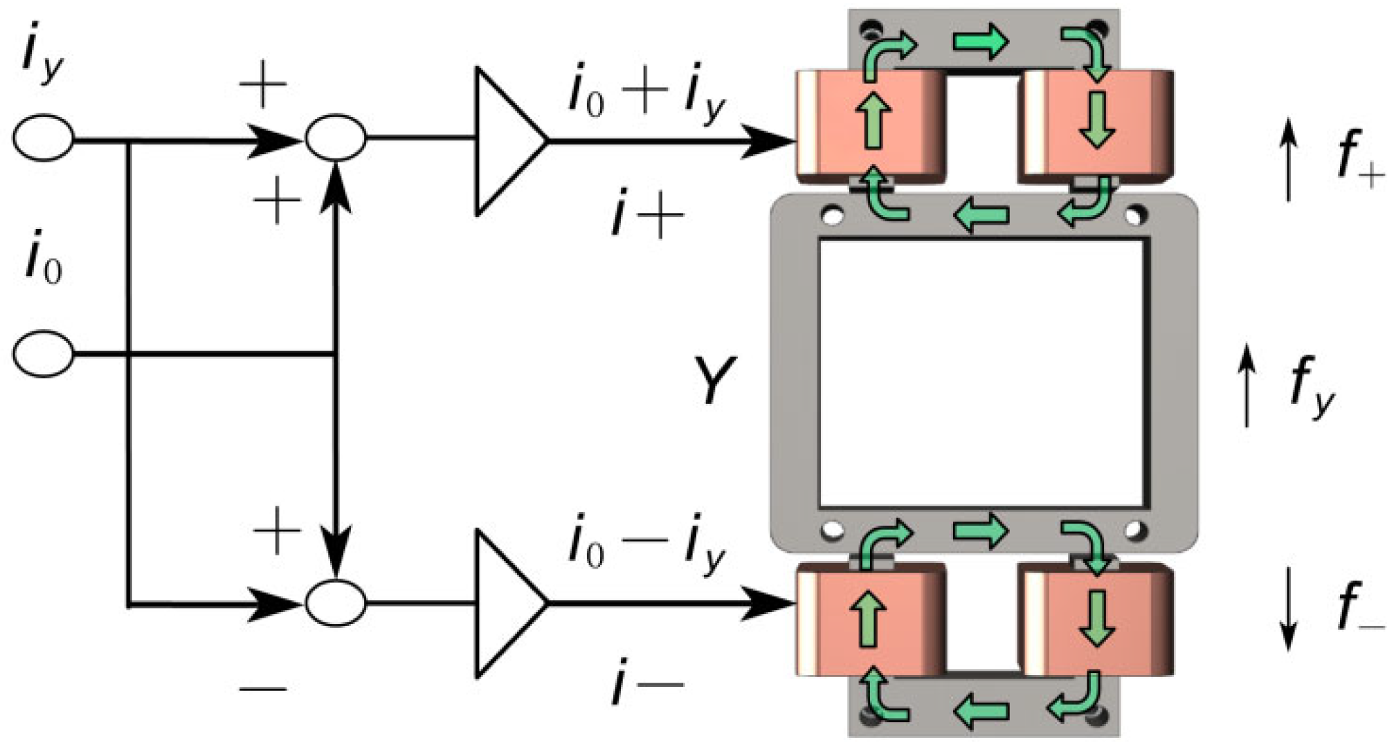
2.2. Magnetic Circuit Analysis
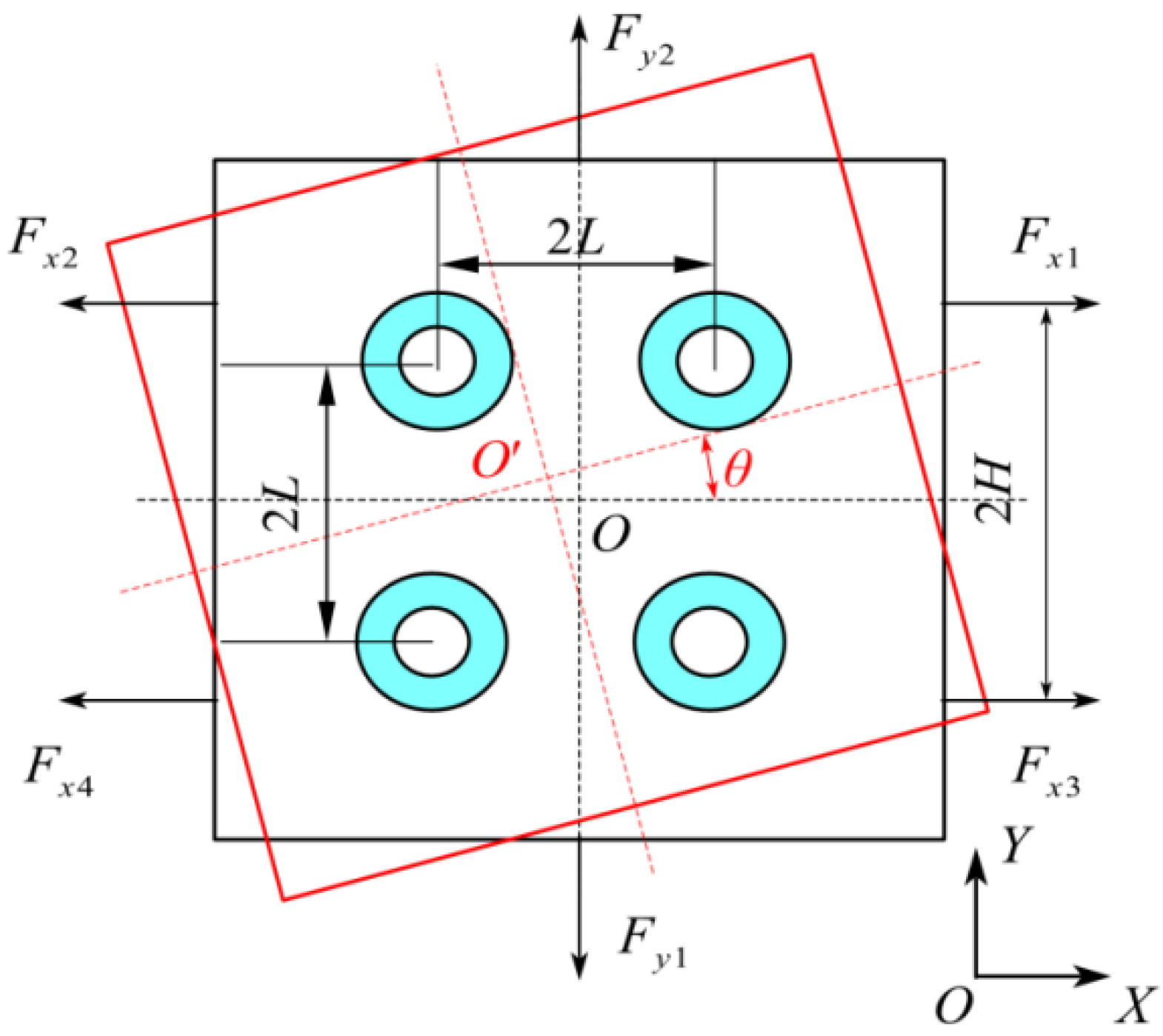
Figure 2 shows the magnetic flux density distribution of the electromagnet and armature. The electromagnetic drive system is composed of three groups of electromagnets and armatures. The air-gap distance between the armature and the electromagnet shown in the figure is 1.5 mm, the number of coil turns is Nx = 235, two coils in the Y direction are connected in series, Ny = 260, and the current is 2A. The magnetic flux that leaked into the air cannot be ignored, and the leakage coefficient varying with the air-gap distance needs to be introduced. As seen in Figure 2, the magnetic flux density of the armature is almost zero. It can be seen from Figure 3 that the flux path starts from the north pole and returns to the south pole through the core. In order to form a specific stiffness when controlling the operation of the orbiting scroll, the system adopts the method of differential control. When the orbiting scroll is stationary, the two electromagnets in the up and down direction of Y are input with bias current and pull the orbiting scroll mutually. When the positive signal in the direction is given, the upper electromagnet current increases, and the lower electromagnet current decreases.

2.3. System Model

The distance measured by the sensor needs to be converted into the air gap between the electromagnet and the armature, and the relationship is shown in Formula (1). As shown in Figure 4, when the displacement of the MDOFSC in the X direction is x, the displacement in the Y direction is y, and the rotation angle of the orbiting scroll around the Z-axis is θ. The transformation relationship between the change of air gap between the three groups of magnetic poles and armature and the three degrees of freedom of the platform is shown in Formula (2). After linear approximation, the coordinate transformation relationship in matrix form can be obtained, as shown in Formula (3). As shown in Formula (4), solve the pseudo-inverse matrix of the coordinate transformation matrix, and the coordinate inverse transformation relationship of the system can be obtained, as shown in Formula (5).
As shown in Figure 4 and Formula (1): Dx, and Dy are the distances between the sensor and the corresponding end face of the electromagnet, which are fixed values; d1, d2, and d3 are the distances between the sensor and the armature; x1, x2, and x3 are the air-gap distances between the end face of the electromagnet and the armature. x, y, and θ are the three degrees of freedom of the suspended solids. 2L1 is the distance between two sensors in the X direction.
[ x 1 x 2 y 1 ] T = [ D x D x D y ] T - [ d 1 d 2 d 3 ] T ,
{ x 1 = x + y tan θ - H sin θ x 2 = x + y tan θ + H sin θ y 1 = - x tan θ + y ,
[ x 1 x 2 y 1 ] T = N 1 [ x y θ ] T ,
N 1 N 2 = E 3 × 3 ,
[ x y θ ] T = N 2 [ x 1 x 2 y 1 ] T ,
where N1 is the coordinate transformation matrix, and N2 is the inverse coordinate transformation matrix.
N 1 = [ 1 1 - H 1 1 H - 1 1 0 ] , N 2 = [   1 / 4   1 / 4 -   1 / 2   1 / 4   1 / 4 1 / 2 - 1 / ( 2 H ) 1 / ( 2 H ) 0 ] ,
As shown in Figure 5, 2H is the center distance between Electromagnet 2 and Electromagnet 4; 2L is the distance from the center of the magnetic spring composed of an annular permanent magnet and a cylindrical permanent magnet to the center of the actuating platform.
In order to analyze the feasibility of the MDOFSC, the control system needs to be simulated. Therefore, the mathematical model describing the controlled object should be established according to the dynamic characteristics of the controlled object. In order to simplify mathematical modeling, this paper assumes that the following complex elements can be ignored. (1) The mass of the suspension platform of the MDOFSC is evenly distributed, and the center of gravity overlaps the geometric center of the platform. (2) The suspended platform is an ideal rigid body; the deformation is negligible. (3) The dimensional accuracy is sufficient, and the magnetic characteristics of each magnetic pole are the same. (4) It is difficult to derive the friction formula between the orbiting scroll and the static scroll, supplemented by increasing the system damping. The force and motion of the platform are shown in Figure 4. Then, the differential formula is established through the force and motion analysis of each degree of freedom, as shown in Formula (6).
{ m   x ¨ = F qx 1 + F qx 2 + 4 F m - c   x ˙ m   y ¨ = F qy + 4 F m - c   y ˙ J   θ ¨ = ( 2 ( F qx 2 - F qx 1 ) H + 8 F m L ) θ - c   θ ˙ ,
F v = k w i 2 ( d w + λ w ) 2 ;   v = x 1 ,   x 2 ,   x 3 ,   x 4 ,   y 1 ,   y 2 ;   w = x ,   y
F w = k w ( ( i 0 + i w d 0 - d w - λ w ) 2 - ( i 0 - i w d 0 + d w + λ w ) 2 ) ,
where m is the mass of suspended solids, Fqx1, Fqx1, and Fqy are three groups of differential electromagnetic forces in X1, X2, and Y directions, respectively, and Fm is the magnetic force of a single group of permanent magnetic rings. The derivation process of the magnetic force of permanent magnetic rings is shown in the paper [5]. J is the rotational inertia of the suspended solids, and Fv is the magnetic force of a single electromagnet. i2 is the input current of the coil, d is the air-gap length between the electromagnet and the magnetized target, Fw is the differential electromagnetic force of a single group of electromagnets, λ w is the compensation constant for the air gap, kw is the constant of magnetic force, i0 is the bias current, iw is the control current, d0 is the air-gap distance at the balance position, and dw is the displacement of the platform. The structure of the electromagnetic system determines the above two parameters.
F m = k m δ ,
Δ F = k iw ( i 0 + i w ) + k dw ( d 0 + d w ) ;   w = x , y
where Km is the stiffness coefficient of the permanent magnetic force, δ. It is the horizontal displacement change between a pair of permanent magnetic rings and the linearization result of a single group of differential electromagnetic forces. Kiw is the current stiffness after linearizing a single group of differential electromagnetic forces, and kdw is the displacement stiffness after linearizing a single group of differential electromagnetic forces. kiw and kdw are current and displacement stiffness coefficients, respectively.
According to the system dynamics formula, the system state space formula is established as follows:
{ X ˙ = A X + B U Y = C X ,
where,
X = [ x   x ˙ θ   θ ˙ y   y ˙ ] T ,
Y = [ y 1 y 2 y 3 ] T ,
U = [ i 1 i 2 i 3 ] T ,
A = [ 0 1 0 0 0 0 2 k x + 4 k m m - c m 0 0 0 0 0 0 0 1 0 0 0 0 2 H 2 k x + 4 L 2 k m J - c J 0 0 0 0 0 0 0 1 0 0 0 0 k y + 4 k m m - c m ]
B = [ 0 0 0 k i x m k i x m 0 0 0 0 - k i x J k i x J 0 0 0 0 0 0 k iy m ]
C = [ 1 0 0 0 0 0 0 0 1 0 0 0 0 0 0 0 1 0 ]

3. Controller Design and System Simulation

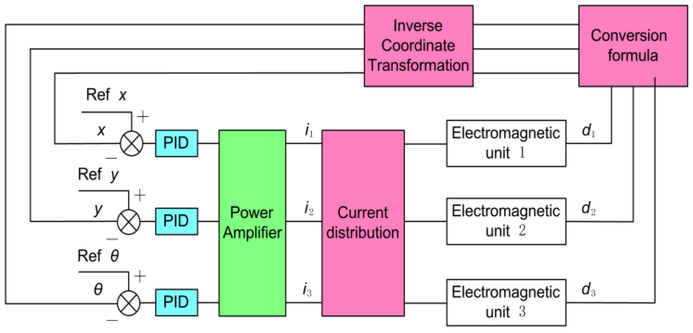
3.1. Motion Controller Design

To solve the deviation problem caused by the different magnetic characteristics of each magnetic pole of the MDOFSC under a decentralized control, a three-degree freedom centralized control strategy is designed to realize the direct control of the freedom of the MDOFSC. There is a coupling between the input and output of the system. The system can be decoupled into three single input and single output systems by Formulas (1) and (5), and PID controller. The integration link can correct the control current of each magnetic pole in real time, compensate for the influence of the difference in magnetic characteristics, and correct the inclination of the orbiting scroll. Figure 6 shows the principle of the controller, and the expression is written as follows:
e du = Ref   u - u ( t ) ;   u = x , y , θ , i u ( t ) = k p u e d u ( t ) + k i u e d u ( t ) d t + k d u d e d u ( t ) d t ,
where edu is the input error signal, Ref u is the reference input of three degrees of freedom, u(t) is the actual degree of freedom of feedback, iu(t) is the input current. The kpu, kiu, and kdu are the proportional gain, integral gain, and differential gain of the PID controller, respectively.

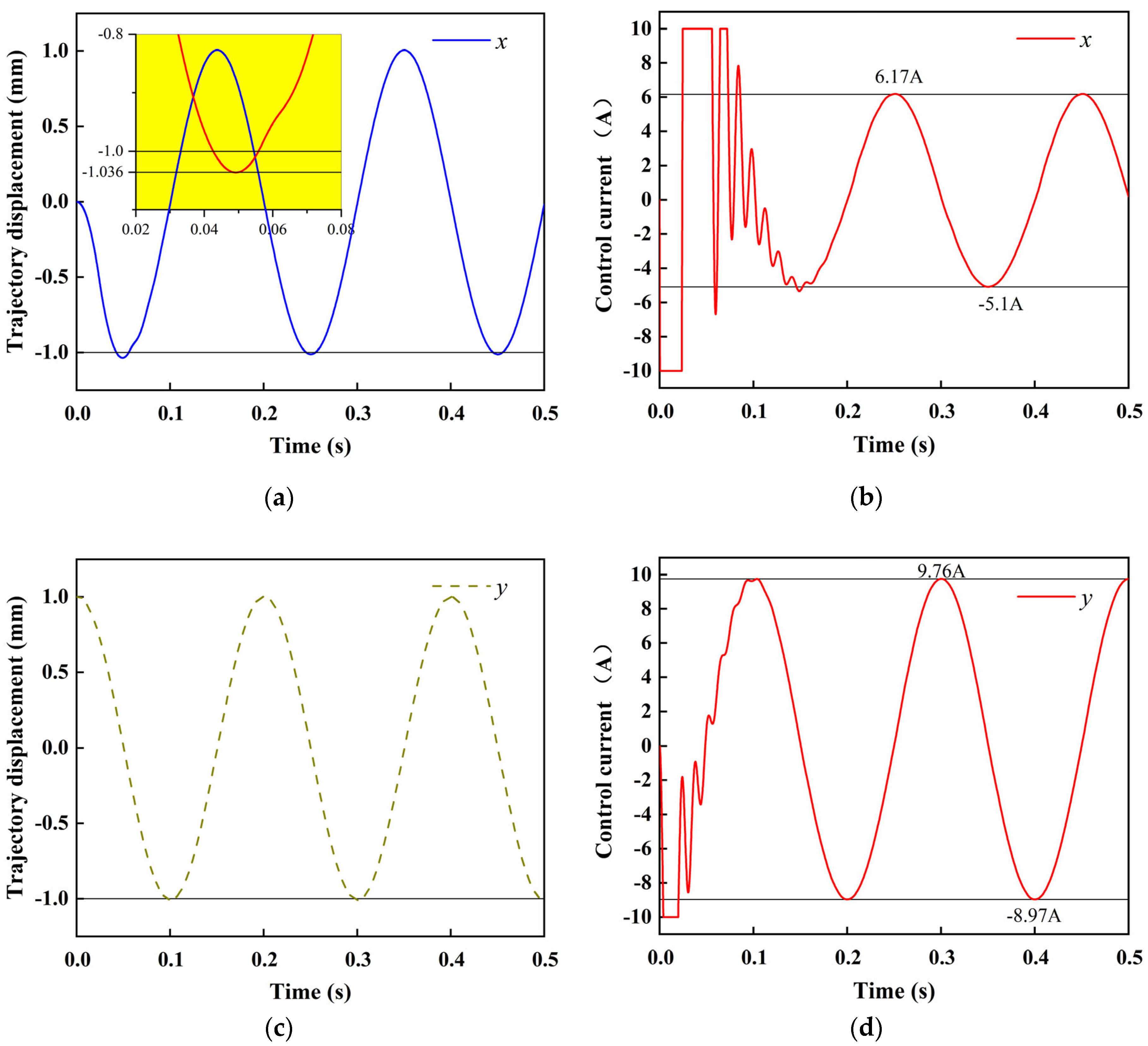
3.2. Control System Simulation

The feasibility of the double closed-loop controller is verified by numerical simulation using Simulink software. Table 1 shows the parameters. In this program, the simulation lasts for 0.5 s, and at 0 s, each electromagnetic unit inputs a signal, respectively. Figure 7 shows the simulation results (track tracking states and corresponding control currents in the X and Y directions). The control parameters in the X direction are P = 100, I = 2, and D = 10. During the movement in the X direction, a negative sinusoidal signal is input in the X direction at 0 s, and the controller quickly inputs a negative current to the electromagnetic unit. This system simulation does not consider the friction between the orbiting scroll and the static scroll, so the system stability is poor, and a larger D is required to enhance the system damping and control effect. However, the differential effect amplifies noise disturbances, causing the control current to oscillate rapidly. The threshold of the control current is ±10 A, and the starting current of track tracking reaches the peak. The peak time of track tracking is 0.053 s, and the maximum overshoot is 3%. The control parameters in the Y direction are P = 30, I = 2, and D = 20. In the trajectory motion in the Y direction, a cosine signal is an input in the Y direction at 0 s, at which time the controller quickly outputs the maximum negative current. The larger D value makes the system have the effect of starting overshoot and strengthening control, which can effectively reduce the dynamic deviation of the control process. There is no overshooting in the trajectory tracking, and the tracking effect is good.

4. Experiment and Analysis

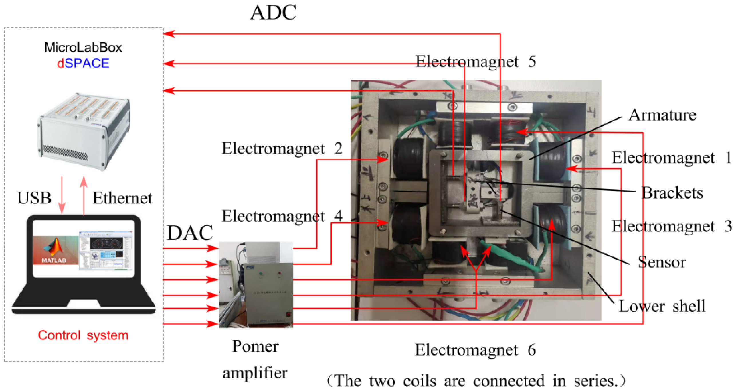
4.1. Experimental System

Figure 8 shows the experimental system of the MDOFSC, mainly including the prototype, hardware equipment, and control system. The control system is based on the MicroLabBox produced by the dSPACE company. MATLAB and dSPACE software kits are installed on the upper computer. The power amplifier adopts the current control mode. Pu-05 eddy current displacement sensor of the AEC company is used for air-gap detection, with a range of 0–2 mm and a resolution of 0.5 μm. The analog output voltage range is −5 V to 5 V.

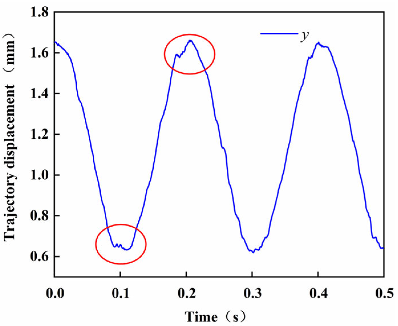
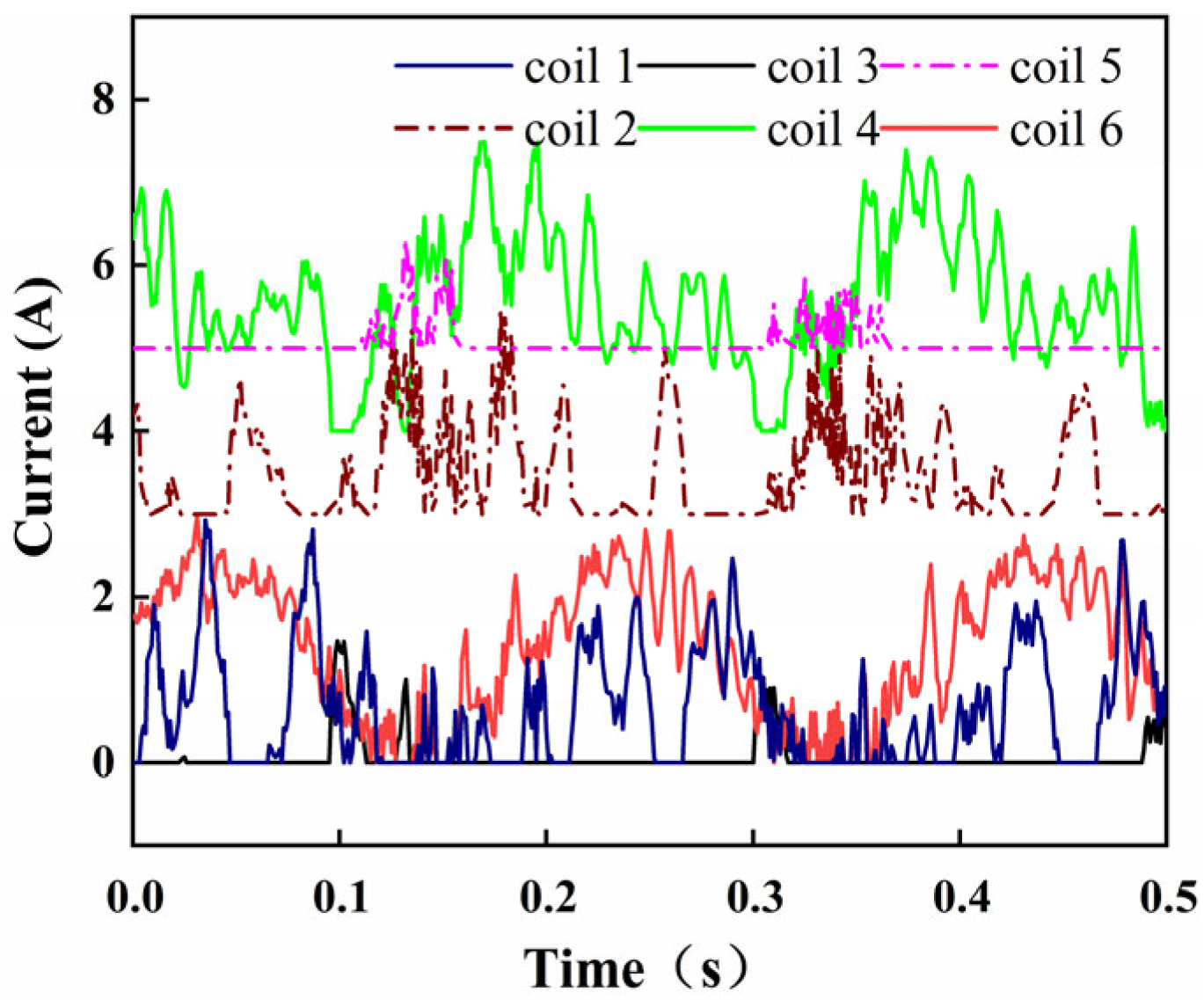
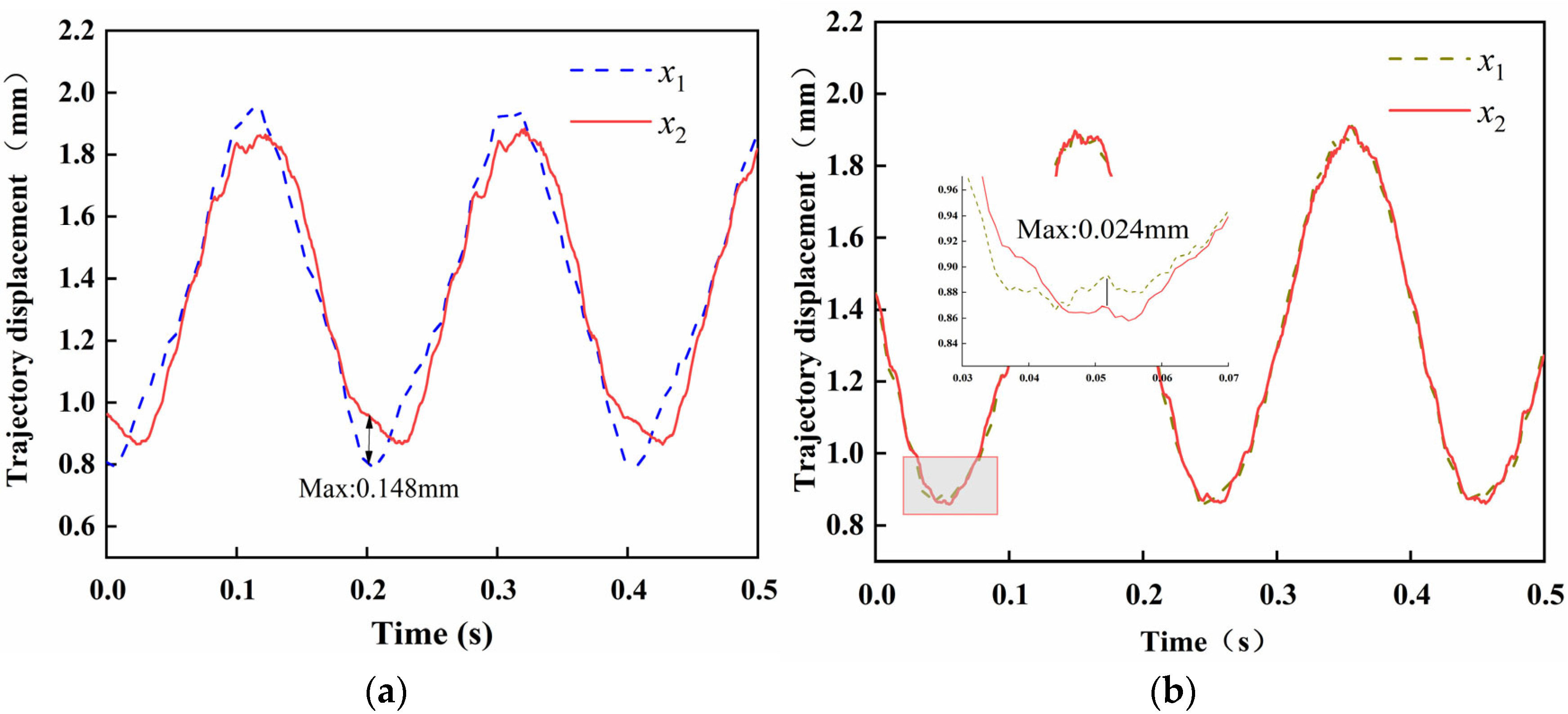
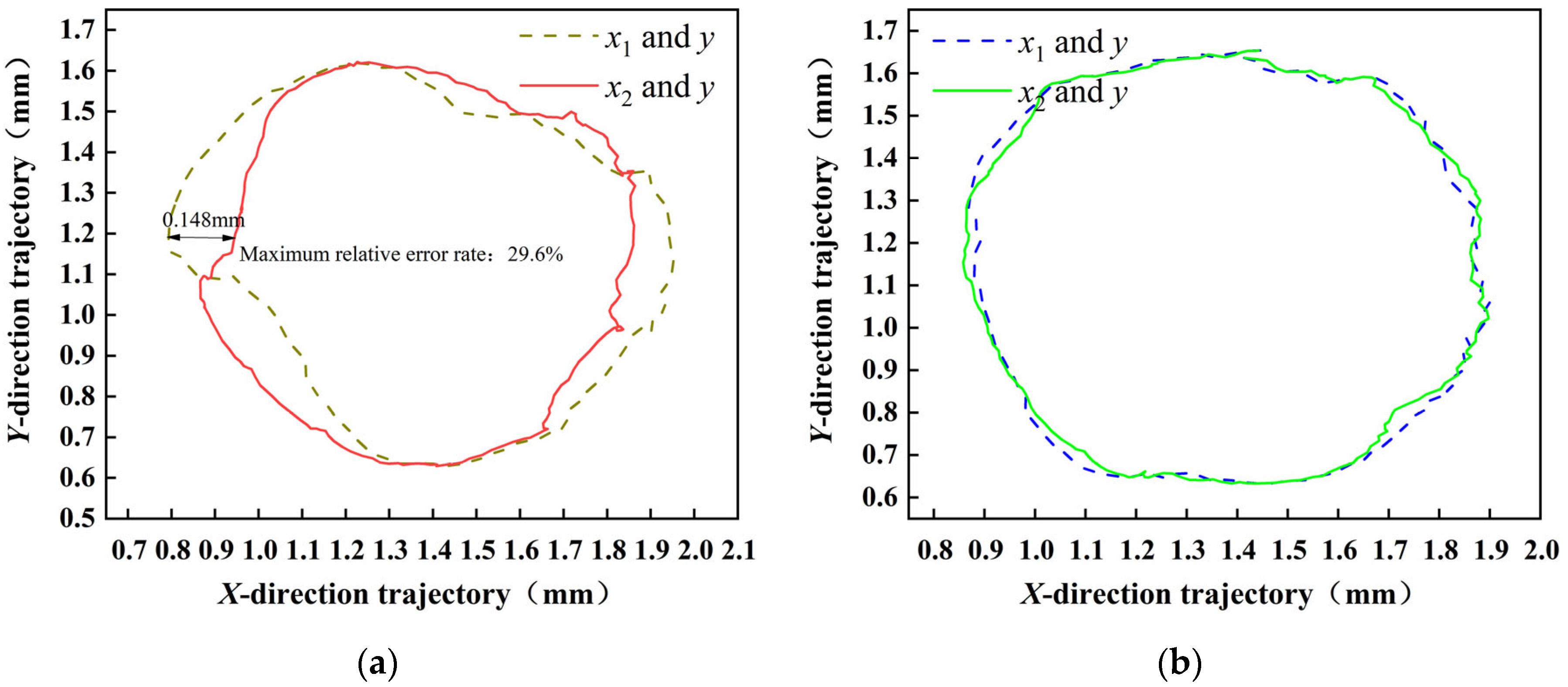
4.2. Experimental Result

Trajectory tracking experimental parameters: P = 30, I = 2, D = 0.01. The parameters of PID come from many experiments. The appropriate parameters are determined by the step experiment’s positioning effect and the trajectory tracking stability. Figure 8 shows the trajectory tracking experiment of the MDOFSC in the X direction. The period is 0.2 s, and the motion track is a circle with a radius of 0.5 mm. It can be seen from Figure 9a that at 0 s, a negative sinusoidal trajectory in the X-axis direction is input. Under PID decentralized control, the track difference between x1 and x2 increases gradually from the track center to the track peak, the maximum time difference reaches 0.148 mm, and the maximum relative error rate is 29.6%. As shown in Figure 9b, the trajectory tracking effect is better. In the whole tracking process, the maximum error of x1 and x2 is 0.024 mm, and the maximum relative error rate is 4.8%. The results show that the centralized control system has a good tracking effect.
Figure 10 shows the tracking track in the Y direction. The cosine displacement signal is input at 0 s. The track tracking is not complete at the second and third peaks, which is quite different from the cosine signal. The reasons are as follows: 1. After the trajectory signal is given, the static scroll changes from static to motion and vibrates due to inertia and magnetic ring interference. It is not easy to control the system. From the fourth peak, the tracking effect is better; 2. PID control is more suitable for linear systems. At the trajectory’s peak, the magnetic unit’s nonlinearity is strong, and the control effect is poor.
Figure 11 shows the current control diagram during track tracking. Figure 8 shows that coils 1, 2, 3, and 4 are in the X direction. When the time is 0, the trajectory signal begins to input, and the orbiting scroll makes a negative sinusoidal motion along the X direction. At this time, the currents of coil 2 and coil 4 are 4.38 A and 6.77 A, which provides the system with high response-ability and provides acceleration. At this time, the current of coil 3 is 0 because the magnetic ring will provide suction to fight against the current of coil 2,4, and the permanent magnet is a passive magnetic force, which is challenging to maintain the stable movement in the X direction, so the current of coil 1 constantly changes. At 0 s, the current of coil 1 starts to rise from 0, which can not only cooperate with the permanent magnetic ring to control the torsion of the orbiting scroll but also pull with coil 2,4 to form a specific stiffness.
Figure 12 shows the trajectory tracking of MDOFSC under decentralized control and centralized control, respectively. Under decentralized control, the circles fitted by the X1 and X2 direction trajectories and the Y direction trajectories have poor coincidence. While under centralized control, x1 and x2, respectively, coincide with the circular trajectory formed by the trajectory in the Y direction. Since the trajectories of x1 and x2 are controlled separately under a decentralized control, the value of x1 and x2 is not always equal due to the hysteresis of position control. By adopting the centralized control method, the three degrees of freedom of the system are directly controlled, and the control rotation angle is always zero. The effect of track tracking is improved, and the coincidence degree of tracks is higher.
An experimental prototype of MDOFSC was built to verify the trajectory tracking experiment. The experimental results show that under a decentralized control, the maximum difference between the synchronization trajectories of x1 and x2 is 0.148 mm, and the maximum relative error rate is 29.6%. Through centralized control after decoupling, the maximum difference between the synchronization trajectories of x1 and x2 is 0.024 mm, and the maximum relative error rate is 4.8%. The results show that through the decoupled centralized control, the system has a self-tuning characteristic, which can ensure that the trajectories of x1 and x2 directions remain constant at all times, reduce the left and right wobble of the orbiting scroll, and reduce the wobble and air leakage during the actual operation of the MDOFSC, which is of great significance for further research on the MDOFSC.

5. Conclusions

This paper introduces the structure and working principle of MDOFSC. Then, the magnetic circuit of the electromagnetic unit is analyzed through finite element simulation, and the mathematical model of MDOFSC no-load operation is established. Finally, the relationship between the air-gap distance and the degree of freedom is decoupled, and the decoupling controller is designed. The trajectory tracking characteristics of MDOFSC are studied through simulation and experiment. Experimental results: Under decentralized control, the maximum difference between x1 and x2 is 0.148 mm, and the maximum relative error rate is 29.6%. Through the centralized control after decoupling, the maximum difference between x1 and x2 is 0.024 mm, and the maximum relative error rate is 4.8%. The experimental results show that the system has self-tuning characteristics through decoupling centralized control, which can ensure that the trajectories of x1 and x2 directions remain unchanged, reduce the left and right swing of the orbiting scroll, and improve the tracking effect of the system. MDOFSC has good trajectory tracking characteristics.

Author Contributions

Conceptualization, F.S., C.S. and F.X.; methodology, F.S., C.S., Q.Z. and J.J.; software, F.S., C.S. and F.X.; validation, F.S., L.T., Q.Z. and J.J.; formal analysis, F.S., F.X., Q.Z. and J.J.; investigation, F.S., C.S., F.X. and K.O.; resources, F.S., K.O. and F.X.; data curation, Q.Z. and L.T.; writing—originaldraft preparation, F.S., C.S., K.O. and L.T.; writing—review and editing, F.S., C.S. and F.X.; visualization, F.S., C.S., F.X. and J.J.; supervision, F.S. and F.X. project administration, F.S.; funding acquisition, F.S. All authors have read and agreed to the published version of the manuscript.

Funding

This research is supported by the National Natural Science Fund of China (No. 52005345, No. 52005344), National Key Research and Development Project (No. 2020YFC2006701), China Scholarship Council (No. 202108210125), Scientific Research Fund Project of Liaoning Provincial Department of Education (No. LFGD2020002), Major Project of the Ministry of Science and Technology of Liaoning Province (No. 2022JH1/10400027).

Conflicts of Interest

The author declares no conflict of interest.

References

  1. Li, B.R.; Zhang, X.; Yang, G.Y. Numerical simulation of interior flow field for oil-free scroll vacuum pump. Vacuum 2016, 53, 7–10. [Google Scholar]
  2. Cardone, M.; Gargiulo, B. Numerical Simulation and Experimental Validation of an Oil Free Scroll Compressor. Energies 2020, 13, 5863. [Google Scholar] [CrossRef]
  3. Li, H.S.; Chen, Y.H.; Wu, K.B.; Zhang, X.W.; Wang, J.S. Structural Design on Tooth Seal of Oil-Free Scroll Compressor. Lubr. Eng. 2015, 40, 13–16. [Google Scholar]
  4. Shi, C.; Sun, F.; Dou, R.; Ren, H.; Li, Q.; Xu, F.; Zhang, X. Modeling and simulation analysis of oil-free scroll compressor driven by magnetic force. Int. J. Appl. Electromagn. Mech. 2020, 64, 1269–1278. [Google Scholar] [CrossRef]
  5. Shi, C.; Xu, F.C.; Sun, F. Mechanical Properties of Scroll Compressor with Permanent Magnetic Compliance Mechanism. J. Southwest Jiaotong Univ. 2022, 57, 597–603. [Google Scholar]
  6. Wang, X.N.; Hu, Y.F.; Wu, H.C.; Dong, R. Research of bearing capacity model of large-air-gap hybrid magnetic bearings. J. Mech. Eng. 2015, 51, 153–160. [Google Scholar] [CrossRef]
  7. Deng, Z. Research and Development Status of High Temperature Superconducting Magnetic Bearings. Trans. China Electrotech. Soc. 2009, 24, 1–8. [Google Scholar]
  8. Li, H.; Deng, Z.; Huang, H.; Liao, H.; Yuan, Y.; Zhang, W. Experiments and Simulations of the secondary suspension system to improve the dynamic characteristics of HTS maglev. IEEE Trans. Appl. Supercond. 2021, 31, 1–8. [Google Scholar] [CrossRef]
  9. Zhu, H.Y.; Teo, D.; Pang, C.K. Magnetically levitated parallel actuated dual-stage (Maglev-PAD) system for six-axis precision positioning. IEEE/ASME Trans. Mechatron. 2019, 24, 1829–1838. [Google Scholar] [CrossRef]
  10. Zhao, C.; Oka, K.; Sun, F.; Harada, A.; Jin, J.; Zhang, M. Design of Zero-Power Control Strategy with Resisting Tilt of Hybrid Magnetic Levitation System. IEEE Trans. Ind. Electron. 2022, 69, 11. [Google Scholar] [CrossRef]
  11. Soni, T.; Dutt, J.K.; Das, A.S. Dynamic Behavior and Stability of Energy Efficient Electro-Magnetic Suspension of Rotors Involving Time Delay. Energy 2021, 231, 120906. [Google Scholar] [CrossRef]
  12. Zhang, X.; Trakarnchaiyo, C.; Zhang, H.; Khamesee, M.B. MagTable: A tabletop system for 6-DOF large range and completely contactless operation using magnetic levitation. Mechatronics 2021, 77, 102600. [Google Scholar] [CrossRef]
  13. Chao, N.; Feng, L.; Wang, Z.M.; Bao, J.; Hu, J. Graphene levitation and orientation control using a magnetic field. J. Appl. Phys. 2018, 123, 044302. [Google Scholar]
  14. Han, B.C.; Qin, J.; Yuan, Q. Multi-objective Optimization of a Combined Radial-Axial Magnetic Bearing for Magnetically Suspended Compressor. IEEE Trans. Ind. Electron. 2016, 63, 2284–2293. [Google Scholar] [CrossRef]
  15. Xu, S.; Sun, J.; Wang, Z. Improved design and analysis of a radial magnetic bearing with paired-pole or alternating-pole configurations. IET Electr. Power Appl. 2022, 16, 382–393. [Google Scholar] [CrossRef]
  16. Yun, L.; Sun, J.; Han, B. Modeling and design of 3-DOF Magnetic Bearing for High-Speed Motor Including Eddy-Current Effects and Leakage Effects. IEEE Trans. Ind. Electron. 2016, 63, 3656–3665. [Google Scholar]
  17. Hosseinzadeh, R.; Martin, F.; Hinkkanen, M. A Dynamic Model for Six-Degree-of-Freedom Bearingless Linear Motor Systems. IEEE Trans. Ind. Appl. 2021, 57, 6921–6930. [Google Scholar] [CrossRef]
  18. Miric, S.; Kuttel, P.; Tuysuz, A.; Kolar, J.W. Design and Experimental Analysis of a New Magnetically Levitated Tubular Linear Actuator. IEEE Trans. Ind. Electron. 2019, 66, 4816–4825. [Google Scholar] [CrossRef]
  19. Zhao, C.; Sun, F.; Pei, W.Z.; Jin, J.J.; Xu, F.C.; Zhang, X.Y. Independent Cascade Control Method for Permanent Magnetic Levitation Platform. J. Southwest Jiaotong Univ. 2022, 57, 618–626. [Google Scholar]
  20. Sun, F.; Pei, W.Z.; Jin, J.J.; Zhao, C.; Xu, F.C.; Zhang, M. Research on Floating Control Method for Permanent Magnetic Levitation Platform Using a Variable Flux Path Mechanism. J. Southwest Jiaotong Univ. 2022, 57, 531–539. [Google Scholar]
  21. Sun, F.; Pei, W.Z.; Zhao, C.; Jin, J.; Xu, F.; Zhang, X. Permanent Maglev Platform Using a Variable Flux Path Mechanism: Stable Levitation and Motion Control. IEEE Trans. Magn. 2022, 58, 7. [Google Scholar] [CrossRef]
  22. Ke, L.; Yan, G.; Yan, S.; Wang, Z.; Li, X. Optimal Design of Litz Wire Coils With Sandwich Structure Wirelessly Powering an Artificial Anal Sphincter System. Artif. Organs 2015, 39, 615–626. [Google Scholar] [CrossRef] [PubMed]
  23. Zhou, Z.; Yan, G.; Wang, Z.; Jiang, P.; Hua, F.; Yao, S.; Ding, Z. Design and Evaluation of Puborectalis﹍ike Artificial Anal Sphincter That Replicates Rectal Perception. Artif. Organs 2020, 44, E300–E312. [Google Scholar] [CrossRef] [PubMed]
  24. Luciani, G.B.; Hoxha, S.; Torre, S.; Rungatscher, A.; Menon, T.; Barozzi, L.; Faggian, G. Improved Outcome of Cardiac Extracorporeal Membrane Oxygenation in Infants and Children Using Magnetic Levitation Centrifugal Pumps. Artif. Organs 2016, 40, 27–33. [Google Scholar] [CrossRef]
  25. Liu, Y.; Wang, S.; Qin, Y.; Guo, H.; Li, Z.; Li, Y.; Tang, J.; Ma, Z.; Liu, J. 5 nm-scale surface evenness movement measurement method based on the electron spin in diamond. Laser Phys. Lett. 2021, 18, 015202. [Google Scholar] [CrossRef]
  26. Yuhki, A.; Nogawa, M.; Takatani, S. Development of a compact, sealless, tripod supported, magnetically driven centrifugal blood pump. Artif. Organs 2015, 24, 501–505. [Google Scholar] [CrossRef]
  27. Forrai, A.; Ueda, T.; Yumura, T. Electromagnetic Actuator Control: A Linear Parameter-Varying (LPV) Approach. IEEE Trans. Ind. Electron. 2007, 54, 1430–1441. [Google Scholar] [CrossRef]
  28. Haisler, W.L.; Timm, D.M.; Gage, J.A.; Tseng, H.; Killian, T.C.; Souza, G.R. Three-dimensional cell culturing by magnetic levitation. Nat. Protoc. 2013, 8, 1940–1949. [Google Scholar] [CrossRef]
  29. Parfenov, V.A.; Mironov, V.A.; Koudan, E.V.; Nezhurina, E.K.; Karalkin, P.A.; Pereira, F.D.; Petrov, S.V.; Krokhmal, A.A.; Aydemir, T.; Vakhrushev, I.V.; et al. Fabrication of calcium phosphate 3D scaffolds for bone repair using magnetic levitational assembly. Sci. Rep. 2020, 10, 4013. [Google Scholar] [CrossRef] [Green Version]
  30. Yaman, S.; Tekin, H.C. Magnetic Susceptibility-Based Protein Detection Using Magnetic Levitation. Anal. Chem. 2020, 92, 12556. [Google Scholar] [CrossRef]
Figure 1. Structure of MDOFSC (a) Overall structure; (b) Suspension mechanism.
Actuators 11 00312 g001
Figure 2. Structure of MDOFSC Magnetic flux density distribution on the electromagnet. Current = 2 A, Air gap x,y = 1.5 mm, and Nx = 235, Ny = 260.
Actuators 11 00312 g002
Figure 3. Magnetic flux path through the U-core electromagnet.
Actuators 11 00312 g003
Figure 4. Relationship between the working air gap and sensor measurement distance.
Actuators 11 00312 g004
Figure 5. Force and motion of the platform.
Actuators 11 00312 g005
Figure 6. Block diagram of the control system.
Actuators 11 00312 g006
Figure 7. Simulation results of trajectory tracking. (a) Trajectory in X direction; (b) Control current in X direction; (c) Trajectory in Y direction; (d) Control current in Y direction.
Actuators 11 00312 g007
Figure 8. Control system hardware.
Actuators 11 00312 g008
Figure 9. Trajectory tracking experiment. (a) X-direction trajectory tracking under decentralized control; (b) X-direction trajectory tracking under centralized control.
Actuators 11 00312 g009
Figure 10. Trajectory tracking in Y-direction under centralized control.
Actuators 11 00312 g010
Figure 11. Control current.
Actuators 11 00312 g011
Figure 12. Trajectory tracking diagram. (a) Trajectory tracking under decentralized control; (b) Trajectory tracking under centralized control.
Actuators 11 00312 g012
Table 1. System parameters.
DescriptionParameterQuantity
Moment of inertiaJ0.0015097 kg·m2
Mass of suspended solidsm1.7 kg
Current stiffness coefficient in the X directionkix150
Displacement stiffness coefficient in the X directionkdx−75
Current stiffness coefficient in the Y directionkiy180
Displacement stiffness coefficient in the Y directionkdy−57
Magnetic stiffness coefficient of a magnetic ring groupkm4.544 N/mm
Damping of the systemc0.015 N/(mm/s)
Center distance between two electromagnets in the X directionH19.5 mm
Center distance of adjacent magnetic ringsL21 mm
Publisher’s Note: MDPI stays neutral with regard to jurisdictional claims in published maps and institutional affiliations.

