
Dynamic and Thermal Investigations of the Forward Dry-Friction Whirl/Whip of a Vertical Rotor-AMB System during Touchdowns


Abstract
1. Introduction
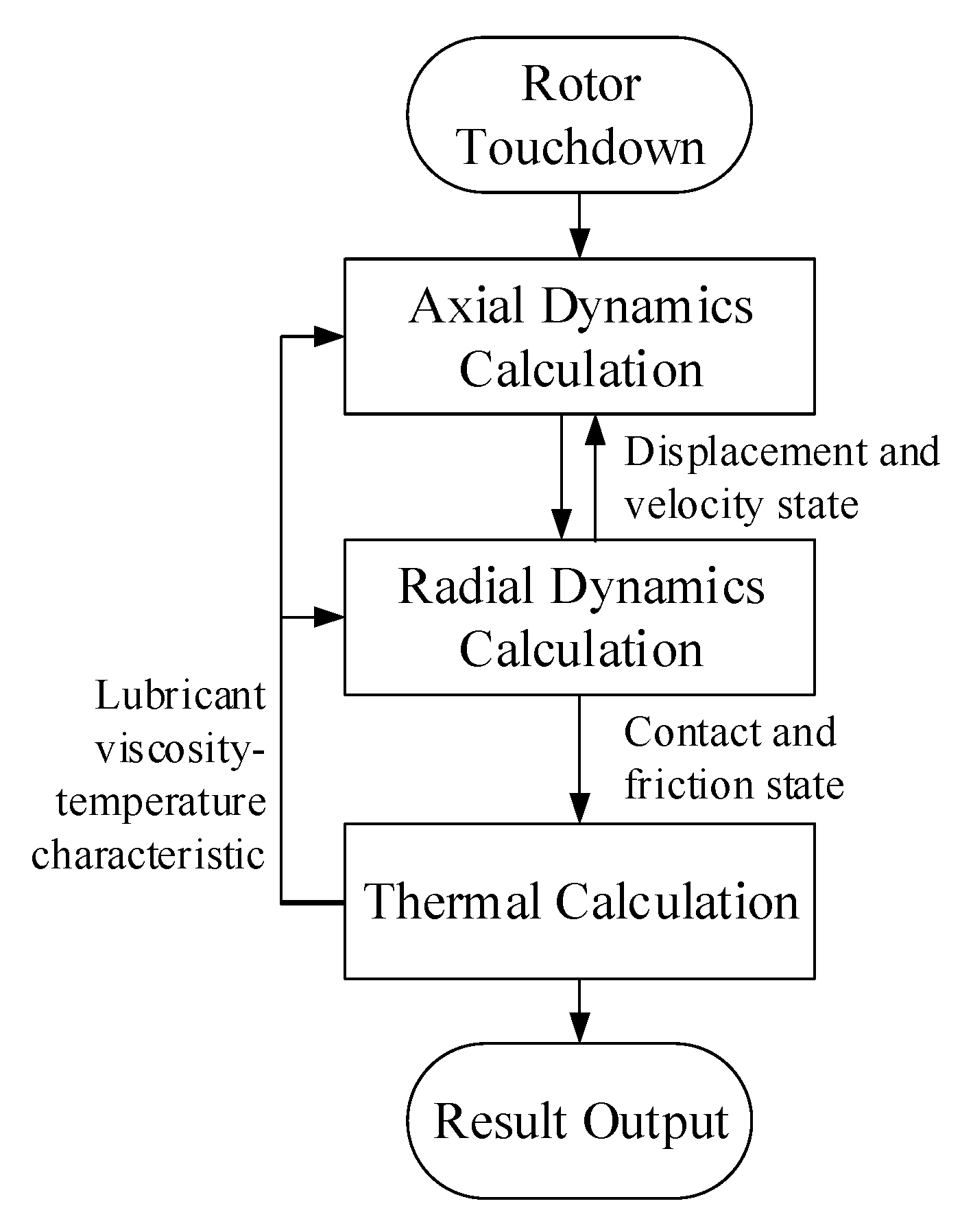
2. Modeling
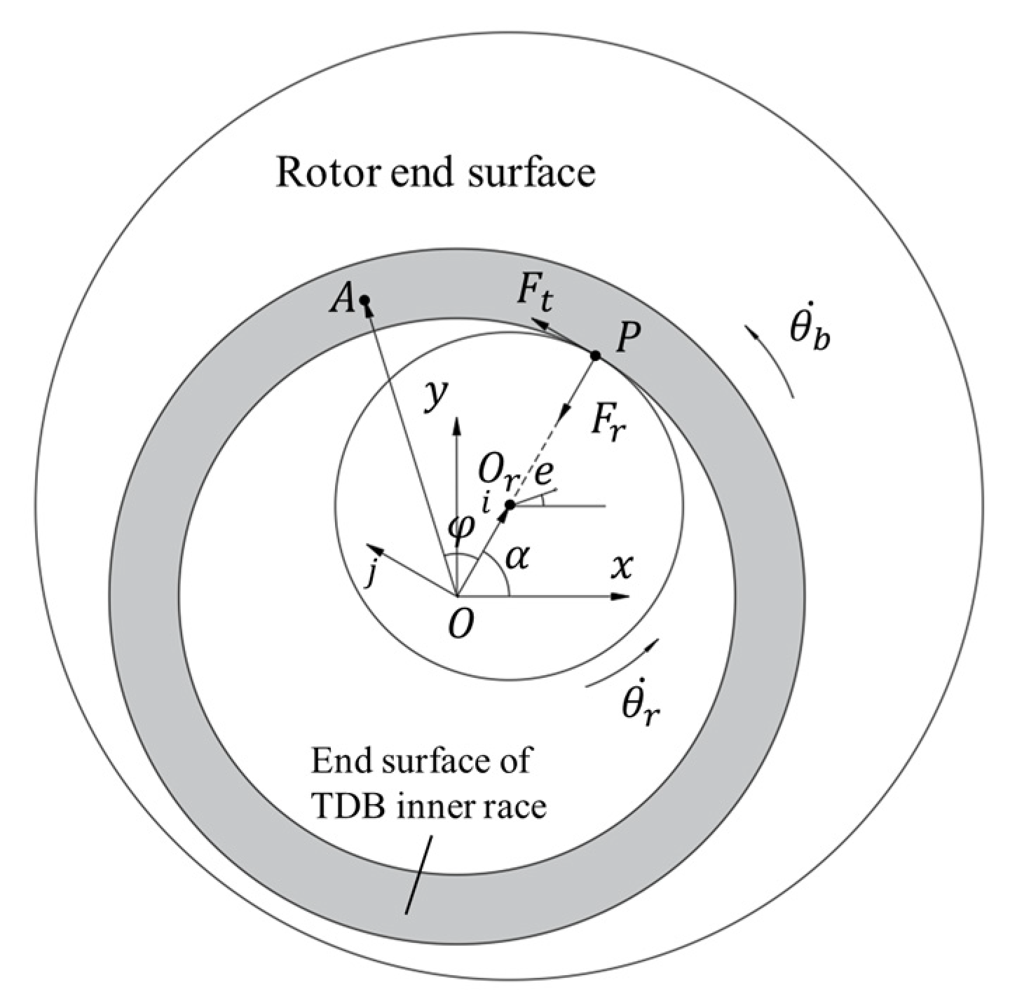
2.1. Friction between the Rotor and TDB
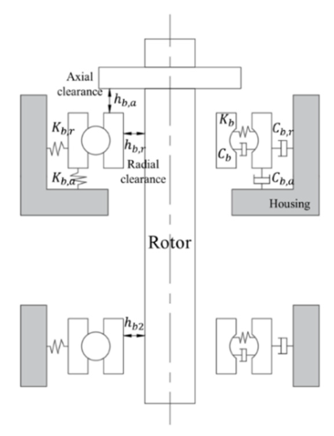
2.2. Dynamics of the Vertical Rotor–TDB System
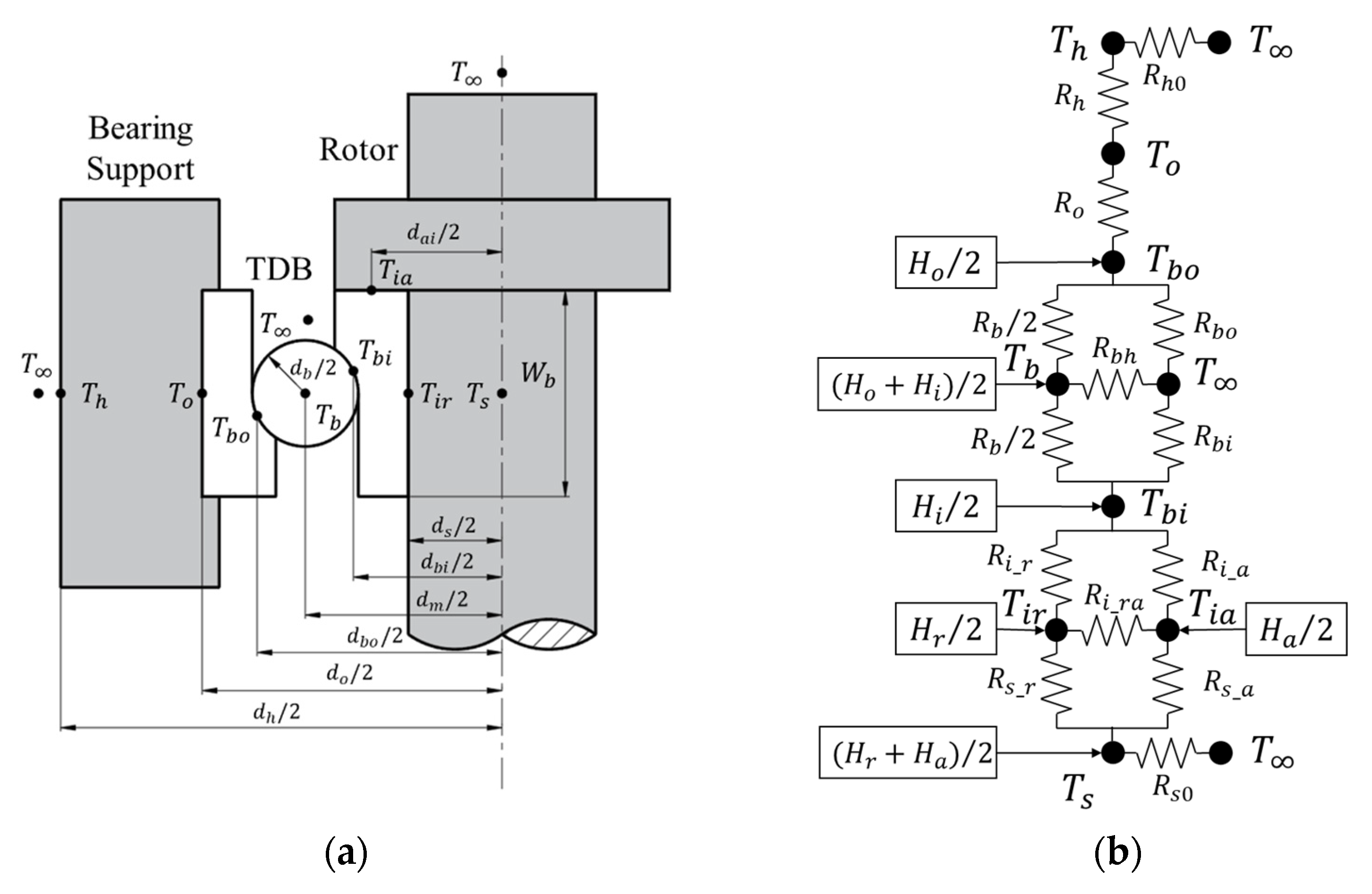
2.3. Thermal Model of the Rotor–TDB System
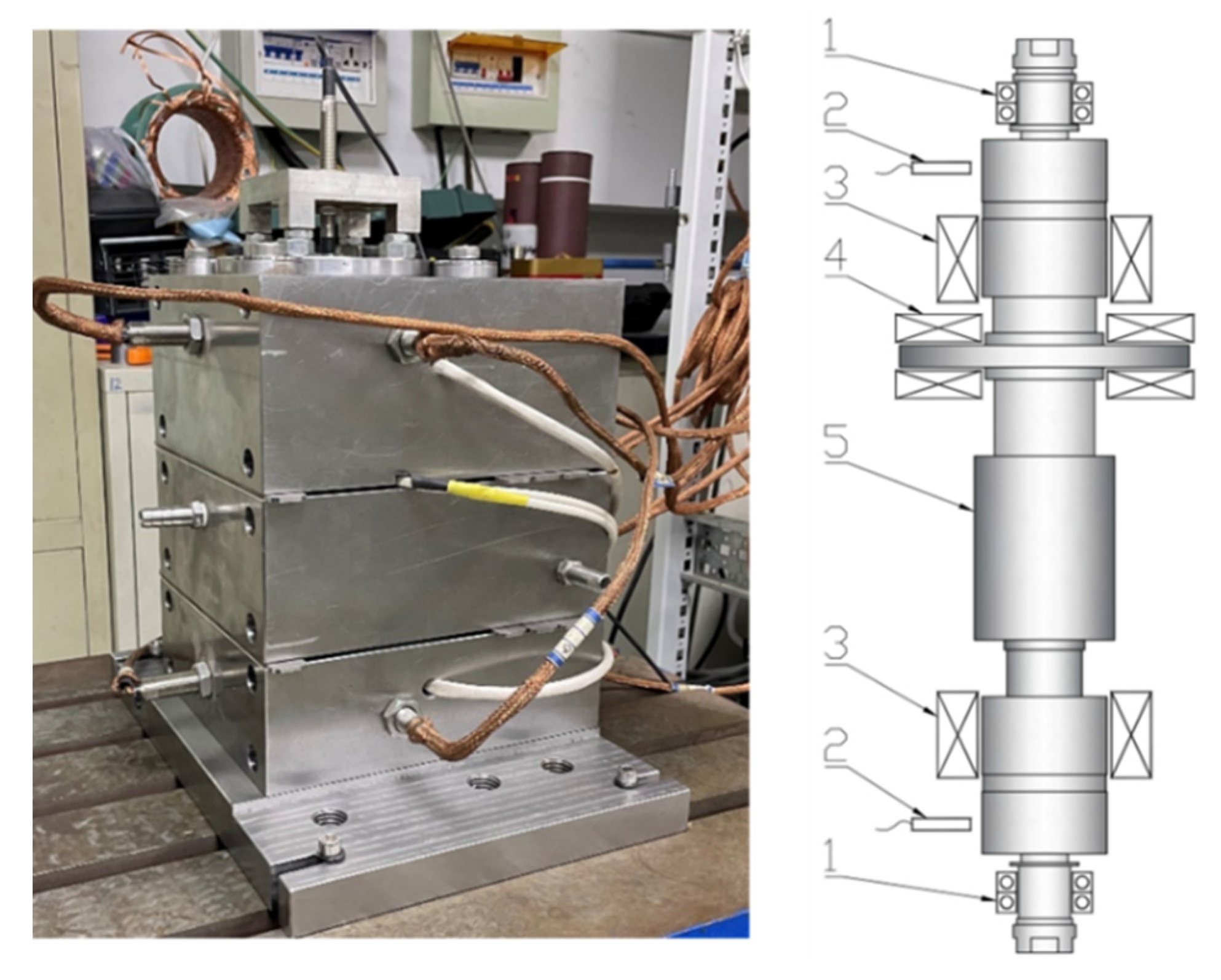
3. Rotor Touchdown Experiments
4. Result and Discussion
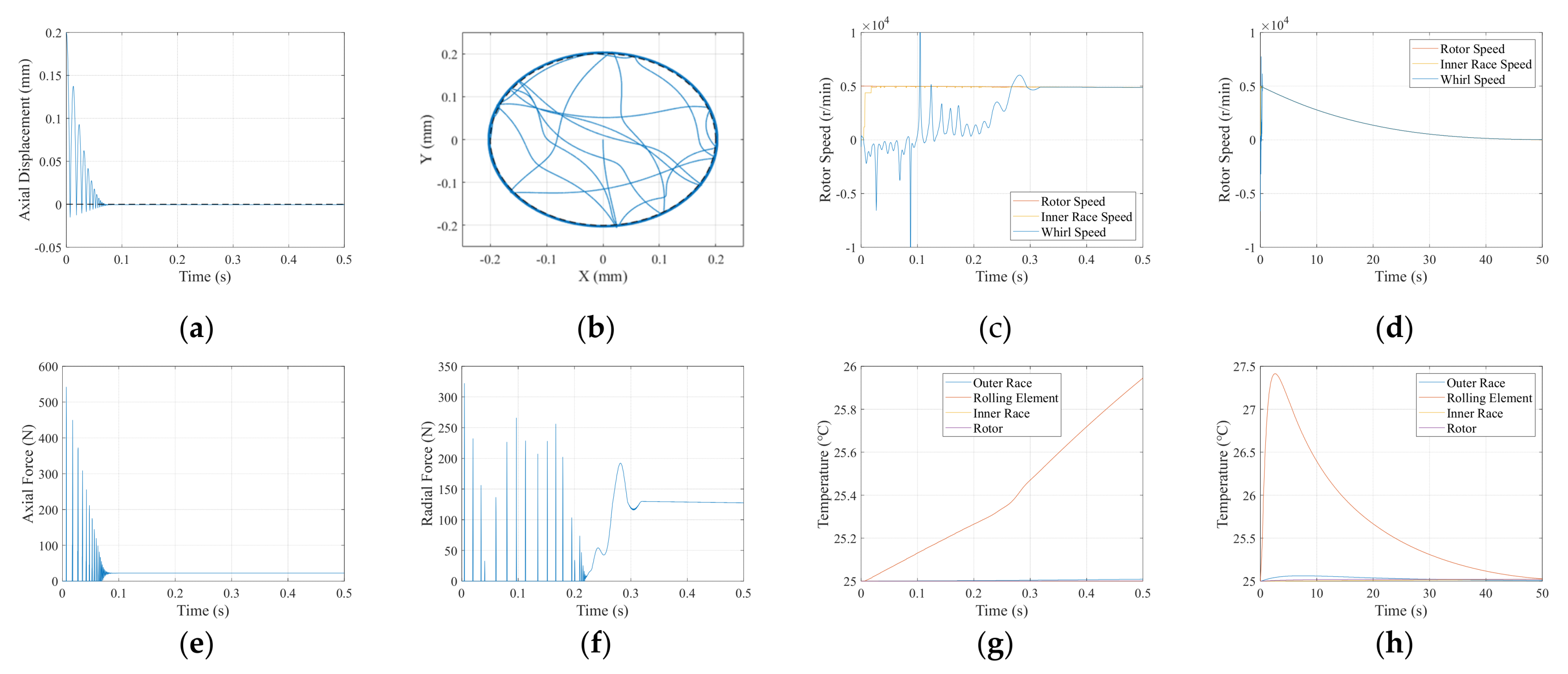
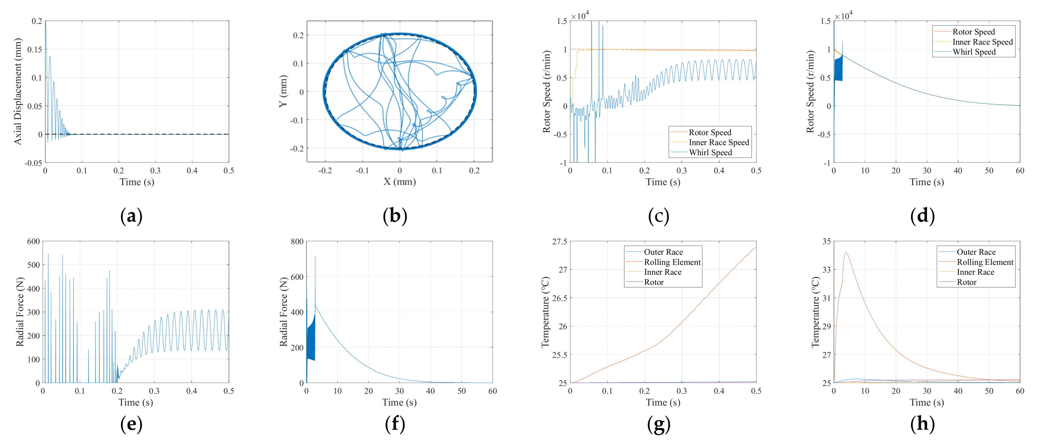
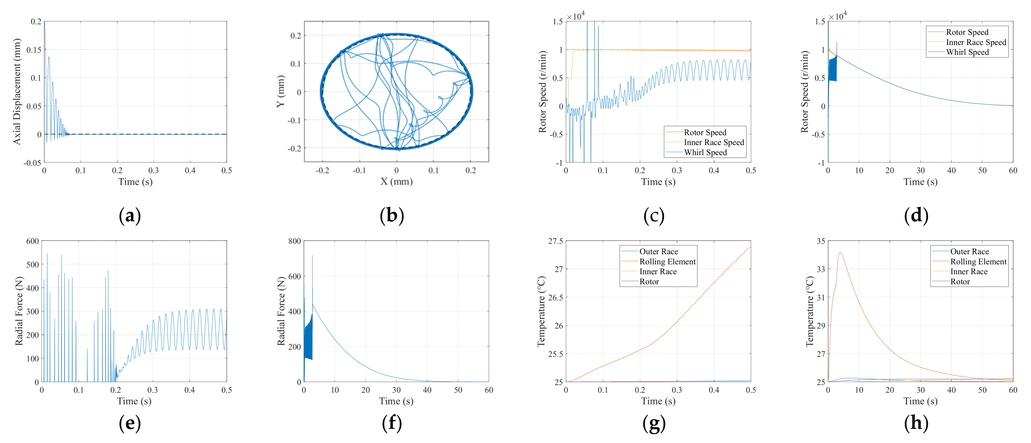
4.1. Simulation Results
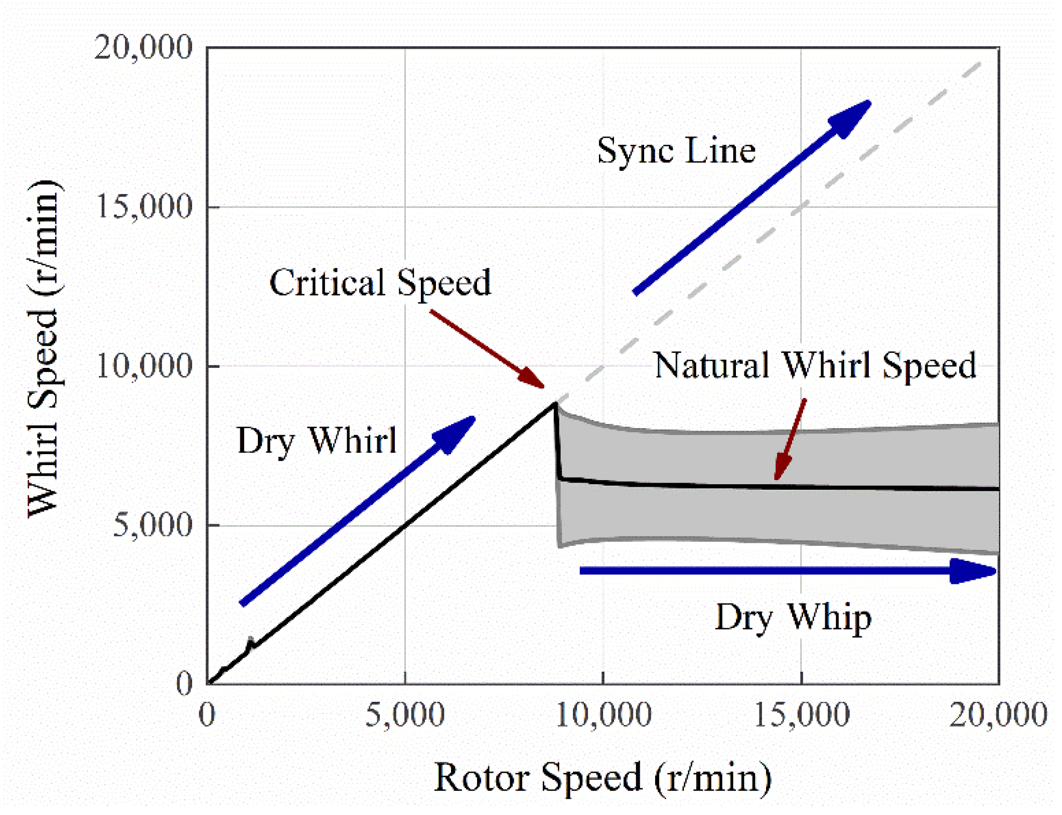
4.2. Model Analysis
- Dry-friction whirl (Dry whirl): the rotor rolls on the surface of the stator without slipping, and the precession frequency is governed by the radius-to-clearance ratio at the contact location;
- Dry-friction whip (Dry whip): the rotor slides continuously on the surface of the stator, and the precession frequency is controlled by the combined natural frequency of the rotor–stator system.
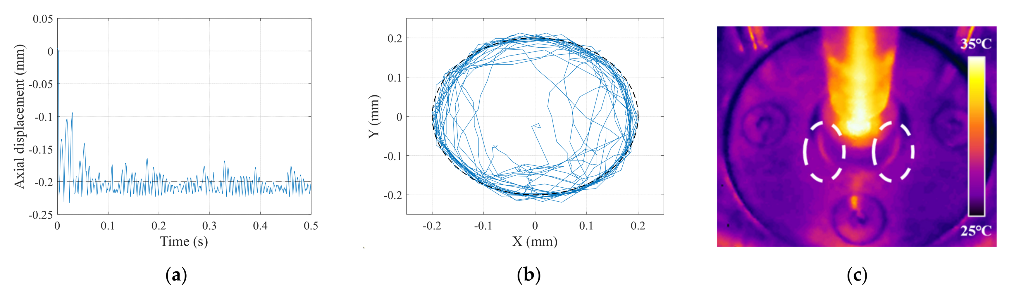
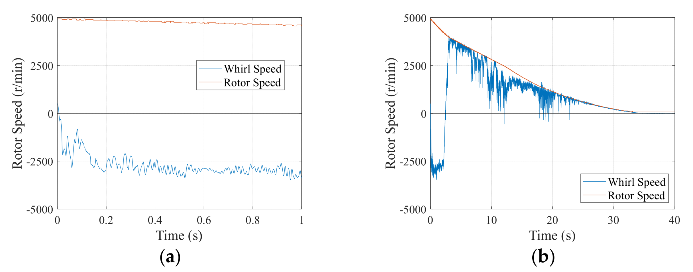
4.3. Experimental Verification
5. Conclusions
Author Contributions
Funding
Conflicts of Interest
Nomenclature
| contact ellipse long semiaxis | |
| diameter of ball, inner ring, outer ring | |
| modulus of elasticity | |
| surface friction media parameter | |
| contact force, frictional force, pressure on the axial end surface | |
| radial impact force and tangential frictional force between rotor and TDB inner ring | |
| axial and radial clearance of rotor and TDB | |
| heat generation | |
| conduction thermal conductivity coefficient | |
| contact stiffness | |
| the second kind of completely elliptic integrals | |
| rotor mass, inertia, and unbalance | |
| friction torque on the axial end surface | |
| friction torque of TDB | |
| radius of curvature in the Hertz model | |
| thermal resistance | |
| inner and outer radius of TDB inner ring | |
| temperature | |
| Poisson’s ratio | |
| relative sliding velocity, radius, and phase angle at point A | |
| number of balls | |
| the nonlinear exponent determined from material and geometric properties of the local region of the contacting bodies | |
| contact coefficient of Hunt-Crossley model, valued 0.08-0.32 s/m | |
| rotational angle of TDB inner ring and rotor | |
| axial and radial friction coefficient between rotor and TDB inner ring | |
| polar coordinate representation of rotor center | |
| Subscripts | |
| axial direction | |
| ball | |
| housing | |
| Inner race | |
| outer race | |
| radial direction | |
| rotor |
References
- Schweitzer, G. Safety and Reliability Aspects for Active Magnetic Bearing Applications—A Survey. Proc. Inst. Mech. Eng. Part I J. Syst. Control Eng. 2005, 219, 383–392. [Google Scholar] [CrossRef]
- ISO 14839-4; Mechanical Vibration—Vibration of Rotating Machinery Equipped with Active Magnetic Bearings Part 4: Technical Guidelines. International Organization for Standardization: Geneva, Switzerland, 2012.
- Lyu, M.; Liu, T.; Wang, Z.; Yan, S.; Jia, X.; Wang, Y. Orbit Response Recognition during Touchdowns by Instantaneous Frequency in Active Magnetic Bearings. J. Vib. Acoust. Trans. ASME 2018, 140, 1–11. [Google Scholar] [CrossRef]
- Lyu, M.; Wang, Z.; Liu, T.; Jia, X.; Wang, Y. Frequency Analysis of the Orbit Responses of Active Magnetic Bearings in Touchdown Using Hilbert Transform. Int. J. Struct. Stab. Dyn. 2017, 17, 17500869. [Google Scholar] [CrossRef]
- Lyu, M.; Liu, T.; Wang, Z.; Yan, S.; Jia, X.; Wang, Y. A Control Method of the Rotor Re-Levitation for Different Orbit Responses during Touchdowns in Active Magnetic Bearings. Mech. Syst. Signal Process. 2018, 105, 241–260. [Google Scholar] [CrossRef]
- Kang, X.; Palazzolo, A.; Zhong, W. Auxiliary Bearing Squeeze Film Dampers for Magnetic Bearing Supported Rotors. Tribol. Int. 2020, 146, 106181. [Google Scholar] [CrossRef]
- Ishii, T.; Kirk, R.G. Transient Response Technique Applied to Active Magnetic Bearing Machinery during Rotor Drop. ASME J. Vib. Acoust. 1996, 118, 154–163. [Google Scholar] [CrossRef]
- Kärkkäinen, A.; Sopanen, J.; Mikkola, A. Dynamic Simulation of a Flexible Rotor during Drop on Retainer Bearings. J. Sound Vib. 2007, 306, 601–617. [Google Scholar] [CrossRef]
- Hunt, K.; Crossley, E. Coefficient of Restitution Interpreted as Damping in Vibroimpact to Cite This Version: HAL Id: Hal-01333795 Coefficient of Restitution Interpreted as Damping in Vibroimpact. J. Appl. Mech. Am. Soc. Mech. Eng. 1975, 42, 440–445. [Google Scholar] [CrossRef]
- Jarroux, C.; Dufour, R.; Mahfoud, J.; Defoy, B.; Alban, T.; Delgado, A. Touchdown Bearing Models for Rotor-AMB Systems. J. Sound Vib. 2019, 440, 51–69. [Google Scholar] [CrossRef]
- Neisi, N.; Sikanen, E.; Heikkinen, J.E.; Sopanen, J. Stress Analysis of a Touchdown Bearing Having an Artificial Crack. Proc. ASME Des. Eng. Tech. Conf. 2017, 8, 1–9. [Google Scholar] [CrossRef]
- Fonseca, C.A.; Santos, I.F.; Weber, H.I. Influence of Unbalance Levels on Nonlinear Dynamics of a Rotor-Backup Rolling Bearing System. J. Sound Vib. 2017, 394, 482–496. [Google Scholar] [CrossRef]
- Halminen, O.; Kärkkäinen, A.; Sopanen, J.; Mikkola, A. Active Magnetic Bearing-Supported Rotor with Misaligned Cageless Backup Bearings: A Dropdown Event Simulation Model. Mech. Syst. Signal Process. 2015, 50–51, 692–705. [Google Scholar] [CrossRef]
- Gupta, P.K.; Taketa, J.I.; Price, C.M. Thermal Interactions in Rolling Bearings. Proc. Inst. Mech. Eng. Part J J. Eng. Tribol. 2020, 234, 1233–1253. [Google Scholar] [CrossRef]
- Sun, G. Auxiliary Bearing Life Prediction Using Hertzian Contact Bearing Model. J. Vib. Acoust. 2006, 128, 203. [Google Scholar] [CrossRef]
- Caprio, M.T.; Murphy, B.T.; Herbst, J.D. Spin Commissioning and Drop Tests of a 130 KW-Hr Composite Flywheel. In Proceedings of the 9th International Symposium on Magnetic Bearings, Lexington, KY, USA, 3–6 August 2004. [Google Scholar]
- Reid, C.M.; Miller, T.B.; Hoberecht, M.A.; Loyselle, P.L.; Taylor, L.M.; Farmer, S.C.; Jansen, R.H. History of Electrochemical and Energy Storage Technology Development at NASA Glenn Research Center. J. Aerosp. Eng. 2013, 26, 361–371. [Google Scholar] [CrossRef]
- Hawkins, L.; McMullen, P.; Vuong, V. Development and Testing of the Backup Bearing System for an AMB Energy Storage Flywheel. In Proceedings of the Turbo Expo: Power for Land, Sea, and Air, ASMEDC, Montreal, QC, Canada, 14–17 May 2007; pp. 1055–1062. [Google Scholar]
- Zhao, Y.; Yang, G.; Shi, Z.; Zhao, L. Thermal Analysis and Simulation of Auxiliary Bearings and Its Application in the High Temperature Reactor-10. J. Tribol. 2016, 138, 011102. [Google Scholar] [CrossRef]
- Wilkes, J.C.; Childs, D.W.; Dyck, B.J.; Phillips, S.G. The Numerical and Experimental Characteristics of Multimode Dry-Friction Whip and Whirl. J. Eng. Gas Turbines Power 2010, 132, 052503. [Google Scholar] [CrossRef]
- Wilkes, J.; Moore, J.; Ransom, D.; Vannini, G. An Improved Catcher Bearing Model and an Explanation of the Forward Whirl/Whip Phenomenon Observed in Active Magnetic Bearing Transient Drop Experiments. J. Eng. Gas Turbines Power 2014, 136, 1–11. [Google Scholar] [CrossRef]
- Jacobs, D.A.; Waldron, K.J. Modeling Inelastic Collisions with the Hunt-Crossley Model Using the Energetic Coefficient of Restitution. J. Comput. Nonlinear Dyn. 2015, 10, 021001. [Google Scholar] [CrossRef]
- Halminen, O.; Aceituno, J.F.; Escalona, J.L.; Sopanen, J.; Mikkola, A. Models for Dynamic Analysis of Backup Ball Bearings of an AMB-System. Mech. Syst. Signal Process. 2017, 95, 324–344. [Google Scholar] [CrossRef]
- Takabi, J.; Khonsari, M.M. On the Thermally-Induced Failure of Rolling Element Bearings. Tribol. Int. 2015, 94, 661–674. [Google Scholar] [CrossRef]


| Parameters | Value |
|---|---|
| Rotor mass | 2.5 kg |
| Rotor length | 293 mm |
| Rotor moment of inertia | 8957.32 × 10−6 kg·m2 |
| Imbalance eccentricity | 1.5 × 10⁻⁵ m |
| Radial magnetic bearings distance | 155 mm |
| Two TDBs’ distance | 253 mm |
| Radial AMB clearance | 0.3 mm |
| Axial AMB clearance | 0.4 mm |
| TDB clearance | 0.2 mm |
| Contact friction coefficient | 0.12 |
| Motor power | 4 kW |
| Bias current | 2 A |
| Radial AMB current stiffness | 81.268 N/A |
| Radial AMB displacement stiffness | −5.864 × 10⁵ N/m |
| Axial AMB current stiffness | 50.26 N/A |
| Axial AMB displacement stiffness | −2.720 × 10⁵ N/m |
| Maximum speed | 36,000 r/min |
Publisher’s Note: MDPI stays neutral with regard to jurisdictional claims in published maps and institutional affiliations. |
© 2022 by the authors. Licensee MDPI, Basel, Switzerland. This article is an open access article distributed under the terms and conditions of the Creative Commons Attribution (CC BY) license (https://creativecommons.org/licenses/by/4.0/).
Share and Cite
Li, Z.; Lyu, M.; Yang, G.; Zhao, J.; Wang, Y.; Wang, Z. Dynamic and Thermal Investigations of the Forward Dry-Friction Whirl/Whip of a Vertical Rotor-AMB System during Touchdowns. Actuators 2022, 11, 291. https://doi.org/10.3390/act11100291
Li Z, Lyu M, Yang G, Zhao J, Wang Y, Wang Z. Dynamic and Thermal Investigations of the Forward Dry-Friction Whirl/Whip of a Vertical Rotor-AMB System during Touchdowns. Actuators. 2022; 11(10):291. https://doi.org/10.3390/act11100291
Chicago/Turabian StyleLi, Zilin, Mindong Lyu, Guojun Yang, Jingjing Zhao, Yuming Wang, and Zixi Wang. 2022. "Dynamic and Thermal Investigations of the Forward Dry-Friction Whirl/Whip of a Vertical Rotor-AMB System during Touchdowns" Actuators 11, no. 10: 291. https://doi.org/10.3390/act11100291
APA StyleLi, Z., Lyu, M., Yang, G., Zhao, J., Wang, Y., & Wang, Z. (2022). Dynamic and Thermal Investigations of the Forward Dry-Friction Whirl/Whip of a Vertical Rotor-AMB System during Touchdowns. Actuators, 11(10), 291. https://doi.org/10.3390/act11100291