Article

Equivalent Rope Length-Based Trajectory Planning for Double Pendulum Bridge Cranes with Distributed Mass Payloads

1
Institute of Robotics and Automatic Information Systems, College of Artificial Intelligence, Nankai University, Tianjin 300350, China
2
Tianjin Key Laboratory of Intelligent Robotics, Nankai University, Tianjin 300350, China
3
Hubei Key Laboratory of Advanced Technology for Automotive Components, Wuhan University of Technology, Wuhan 430070, China
4
School of Automotive Engineering, Wuhan University of Technology, Wuhan 430070, China
*
Authors to whom correspondence should be addressed.
Actuators 2022, 11(1), 25; https://doi.org/10.3390/act11010025
Submission received: 27 December 2021 / Revised: 11 January 2022 / Accepted: 15 January 2022 / Published: 17 January 2022
(This article belongs to the Special Issue Learning and Control of Underactuated Mechanical System)

Abstract

:
The hoisting form in which the payload is hung on the hook by two rigging ropes is widely used in the industry, but it also results in the complex double pendulum dynamic of the bridge crane, making the anti-swing trajectory planning full of challenges. In this paper, based on the concept of the equivalent rope length, an equivalent single pendulum model of the double pendulum bridge crane with the distributed mass payload is established. On this basis, the particle swarm optimization algorithm is adopted to solve the equivalent rope length and calculate the parameters of the anti-swing velocity trajectory based on the phase plane method. To evaluate the effectiveness of the proposed method, experiments with a laboratory double pendulum bridge crane are conducted. Experimental results demonstrate that the residual oscillation angle of the payload of the proposed method is smaller than those of the existing methods, such as the trajectory planning without the equivalent rope length, input shaping and command smoothing.

1. Introduction

As an indispensable transportation equipment, bridge cranes play a significant role in practice and are widely used in the steel industry, assembly workshops, and material warehouses and other modern industries. As an underactuated system, bridge cranes realize the transportation of the payload by controlling the movement of the cart and trolley. Compared with full-actuated systems, underactuated systems require smaller actuators, which will help save energy, reduce costs, and increase system flexibility [1,2]. However, velocity variations of the cart and trolley will inevitably result in payload oscillations. The oscillation of the payload for a longer time will seriously reduce the industrial productivity and even introduce safety issues [3]. In addition, movements of the hook and payload cannot be directly controlled in the double pendulum crane system, which makes the control issue full of challenges.
Numerous methods have been proposed for different types of double pendulum crane systems, such as bridge cranes [4,5,6], tower cranes [7], gantry cranes [8,9] and boom cranes [10,11,12], which are mainly divided into feedback control and open-loop control. In detail, feedback control methods of the double pendulum crane system include proportional integral derivative (PID) control [13], state feedback control [14], sliding mode control [15], enhanced-coupling control [16], adaptive tracking control [17], fuzzy control [18], neural network control [19], etc. In addition, hybrid control methods combining feedback control and open-loop control are proposed to obtain better control performance. The model reference command shaping as a feedforward is combined with a PID controller to achieve a precise trolley positioning and satisfactory oscillation control [20]. Meanwhile, swarm intelligence algorithms such as particle swarm optimization (PSO) [21,22], inspired by biology, are utilized to solve the control problems of the complex system by the cooperation of simple individuals. In [23], the PID controller is proposed for the double pendulum bridge crane and the PSO is designed to obtain the optimal parameters of the PID controller. In addition, the remarkable feature of the feedback control is that it needs the feedback information of the system state. In industrial applications, system states including the trolley position, and the oscillations of the hook and the payload can be measured by various sensors. However, additional sensors will increase costs, and there are many difficulties in the practical application such as installation, power supply, and maintenance, especially for the measurement of the oscillation angle of the payload in the double pendulum crane system [24].
Open-loop control is also an effective method to suppress the oscillations of the payload, including the input shaping [25], model reference command shaping [26], trajectory planning [27,28], and so on. In detail, the input shaping is to suppress the oscillation of the payload by determining the amplitude and time of the acceleration [29]. In addition, the improved input shaping is proposed to improve the robustness of the system [30]. The model reference command shaping utilizing a reference model is proposed for the oscillation control of multimode flexible systems [31]. In addition, considering state or driving constraints, trajectory planning methods based on system dynamics analysis are proposed to suppress the oscillation of the payload [27,28].
The above control methods for the double pendulum crane system have achieved some meaningful results, but the hook and payload are usually roughly regarded as a point mass. In industrial applications, large payloads such as automobile molds, airplane wings, and wind turbine blades are usually hoisted by utilizing multiple rigging ropes. In such cases, the complex dynamics of the crane system cannot be fully described by the point mass model. In recent years, to suppress the oscillations of the hook and distributed mass payload (DMP), the command smoothing method is proposed based on the input shaping technology [32], and experimental results on bridge crane [33] and tower crane [34] demonstrate the effectiveness of the proposed method. In our previous work, a trajectory planning method was proposed to suppress the oscillations of the double pendulum bridge crane hoisting the DMP [35], however, the proposed method was also accompanied by a complex structure and a huge amount of calculations, which increases the performance requirements of the controller.
Furthermore, based on different control objectives, the existing methods can be divided into the displacement control mode and the velocity control mode. Specifically, the displacement control mode is designed for automatic control to achieve the point-to-point transportation of the payload by the preset target displacement. However, in some cases, the target displacement may be random; for example, the parking location of a loading vehicle in a warehouse may be different each time. In such a case, the velocity control mode that controls the crane to operate to a desired velocity will be more suitable than the displacement control mode. In addition, the velocity control mode is more in line with the operator’s working habits, that is, the operating velocity of the crane can be directly determined by the operator. Therefore, the velocity control mode is usually applied to the manual operation, meanwhile, it is also suitable for automatic control under a certain target displacement. In this paper, the velocity control mode will be considered.
To solve the above problems, based on the velocity control mode, this paper will propose an anti-swing trajectory planning with the equivalent rope length (ERL). First, the concept of the ERL is proposed to transform the double pendulum bridge crane with the DMP into the single pendulum system. Then, the PSO is utilized to establish the mathematical model of the ERL and solve the parameters of the anti-swing velocity trajectory based on the phase plane method. Meanwhile, the penalty function is designed to satisfy the physical constraints of the system. The main difference between the proposed trajectory planning and the existing trajectory planning [35] is that the proposed method can reduce the complexity of the controller and obtain a smaller residual oscillation angle of the payload. Finally, the effectiveness of the proposed anti-swing trajectory planning with the ERL is verified by the self-built experimental platform.
The main contributions of this paper are listed as follows:
(1)
The concept of the equivalent rope length is proposed to transform the complex double pendulum crane system with the DMP into an equivalent single pendulum crane system;
(2)
The mathematical model of the ERL is established and the anti-swing trajectory planning with the ERL is proposed;
(3)
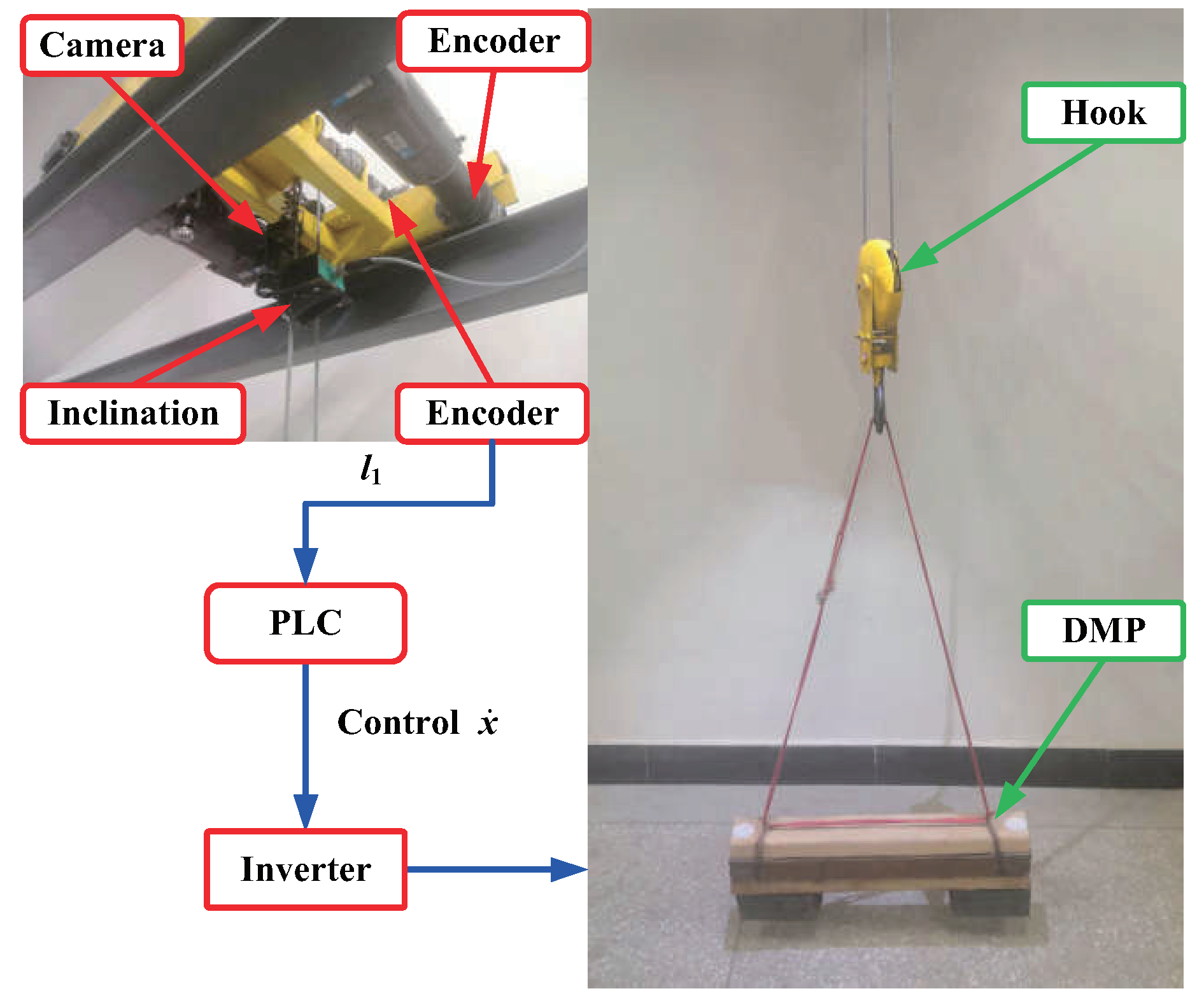
The effectiveness of the proposed method is verified by the hardware platform including PLC, inverter and asynchronous motor.

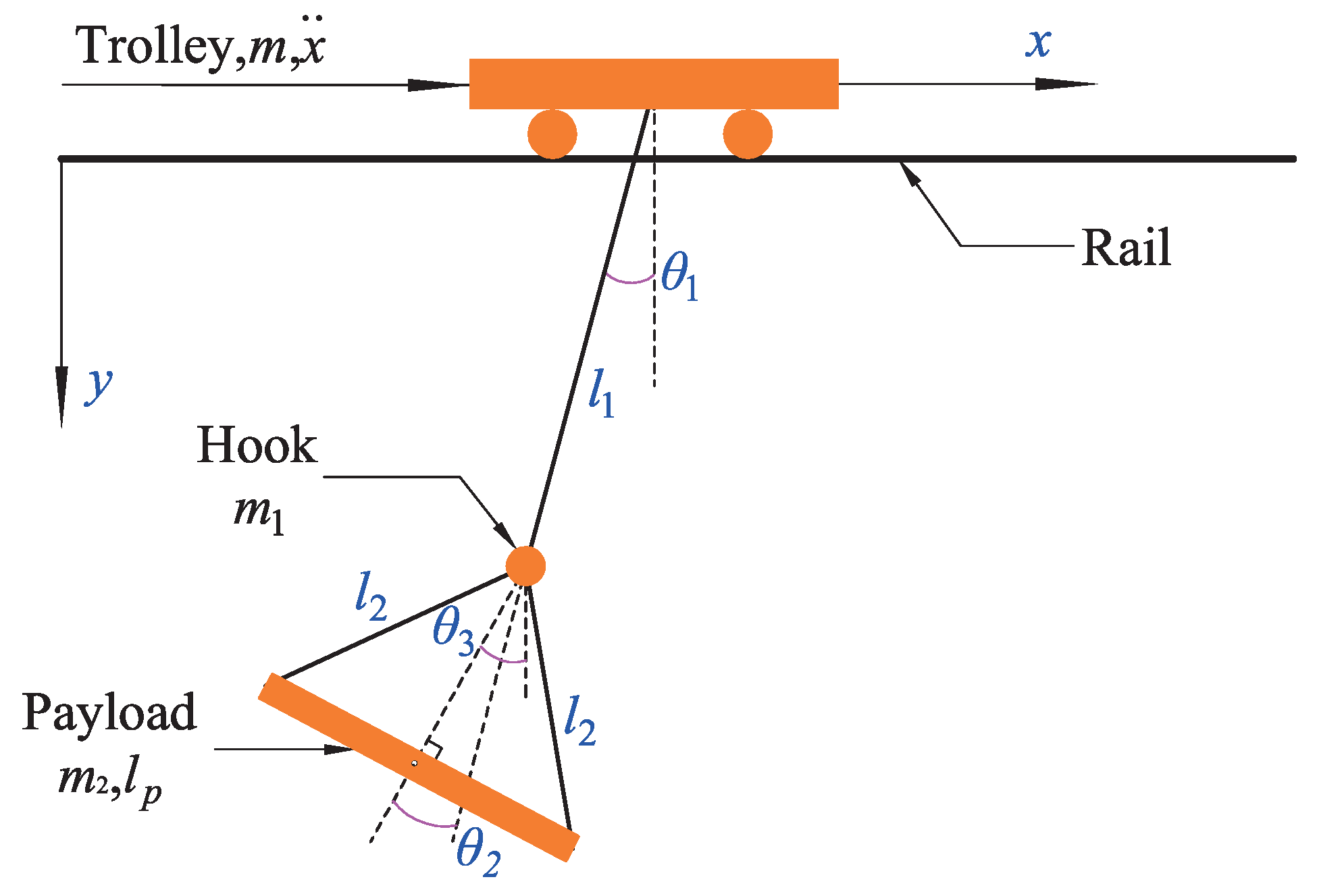
2. Model of the Double Pendulum Crane with the DMP

The schematic of the double pendulum bridge crane hoisting the DMP is illustrated in Figure 1. The damping ratio of the crane system is assumed to be zero [32]. The DMP is suspended from the hook by two rigging ropes, and the hook is suspended from the trolley below the trolley by the hoisting rope. All of them can be transported by the trolley’s movement. m , m 1 and m 2 are the trolley mass, hook mass, and DMP mass, respectively. l 1 , l 2 , l p and x ¨ indicate the hoisting rope length, rigging rope length, DMP length, and acceleration of the trolley, respectively. θ 1 and θ 2 are the oscillation angle of the hook and DMP. θ 3 indicates the oscillation angle of the DMP deviating from the vertical lifting center. l h expresses the vertical distance from the hook to the DMP, which can be calculated by l h = l 2 2 ( 0.5 l p ) 2 .
Based on the geometric position relationship of the bridge crane in Figure 1, the positions of the trolley ( x 1 , y 1 ), hook ( x 2 , y 2 ), and DMP ( x 3 , y 3 ) can be obtained as follows:
x 1 = x y 1 = 0 x 2 = x l 1 sin θ 1 y 2 = l 1 cos θ 1 x 3 = x l 1 sin θ 1 l h sin θ 1 + θ 2 y 3 = l 1 cos θ 1 + l h cos θ 1 + θ 2
Utilizing Lagrange’s method, the nonlinear dynamic equations of the double pendulum bridge crane with the DMP can be obtained as follows [36]:   
m 1 m 2 m x ¨ + m 1 l 1 cos θ 1 + m 2 l h cos θ 1 + θ 2 + m 2 l 1 cos θ 1 θ ¨ 1 + m 2 l h cos θ 1 + θ 2 θ ¨ 2 m 1 l 1 sin θ 1 + m 2 l h sin θ 1 + θ 2 + m 2 l 1 sin θ 1 θ ˙ 1 2 m 2 l h sin θ 1 + θ 2 θ ˙ 2 2 2 m 2 l h sin θ 1 + θ 2 θ ˙ 1 θ ˙ 2 = F f
l 1 2 + R I 2 + R l 1 2 + R l h 2 + 2 R l h l 1 cos θ 2 θ ¨ 1 + R I 2 + R l h 2 + R l 1 l h cos θ 2 θ ¨ 2 R l h l 1 sin θ 2 θ ˙ 2 2 2 R l h l 1 sin θ 2 θ ˙ 1 θ ˙ 2 + l 1 g sin θ 1 + R g l h sin θ 1 + θ 2 + R g l 1 sin θ 1 = l 1 cos θ 1 + R l h cos θ 1 + θ 2 + R l 1 cos θ 1 x ¨
I 2 + l h 2 + l 1 l h cos θ 2 θ ¨ 1 + I 2 + l h 2 θ ¨ 2 + l h l 1 sin θ 2 θ ˙ 1 2 + g l h sin θ 1 + θ 2 = l h cos θ 1 + θ 2 x ¨
where g is the gravitational acceleration, I 2 = l p 2 / 12 , F x and f indicate the actuating force and the friction force, respectively, R = m 2 / m 1 .
According to above dynamic equations, the control mode can be divided into the force ( F f ) control and the acceleration x ¨ control. When the the force control mode with three equations is applied, the friction should be considered. However, considering the complex application conditions of the crane and the diversity payload, it is difficult to establish the friction model. In addition, based on the force control mode, more parameters (such as the mass of the trolley, m) will be introduced into the controller, which will not be conducive to the design and application of the controller. In practical applications, the acceleration control mode considering the latter two dynamic equations will be easier to apply in the industry. Meanwhile, the inverter with frequency control is widely used in the crane control system. Therefore, the acceleration mode will be adopted in this paper.
In addition, considering the practical constraints of the crane system, the operation velocity of the trolley should be within the maximum velocity v m a x . Meanwhile, the opposite moving direction of the trolley is prohibited in the operation. In sum, the velocity of the trolley should be restricted such that:
0 x ˙ v max

3. Anti-Swing Trajectory Planning with the ERL

This section will introduce the design of the anti-swing trajectory planning for the oscillation suppression of the double pendulum crane system with the DMP. First, the concept of the equivalent rope length (ERL) will be proposed to transform the double pendulum bridge crane with the DMP into the equivalent single pendulum model. On this basis, the anti-swing trajectory planning will be designed. Finally, the mathematical model of the ERL and parameters of the proposed anti-swing trajectory planning are determined by utilizing the PSO.

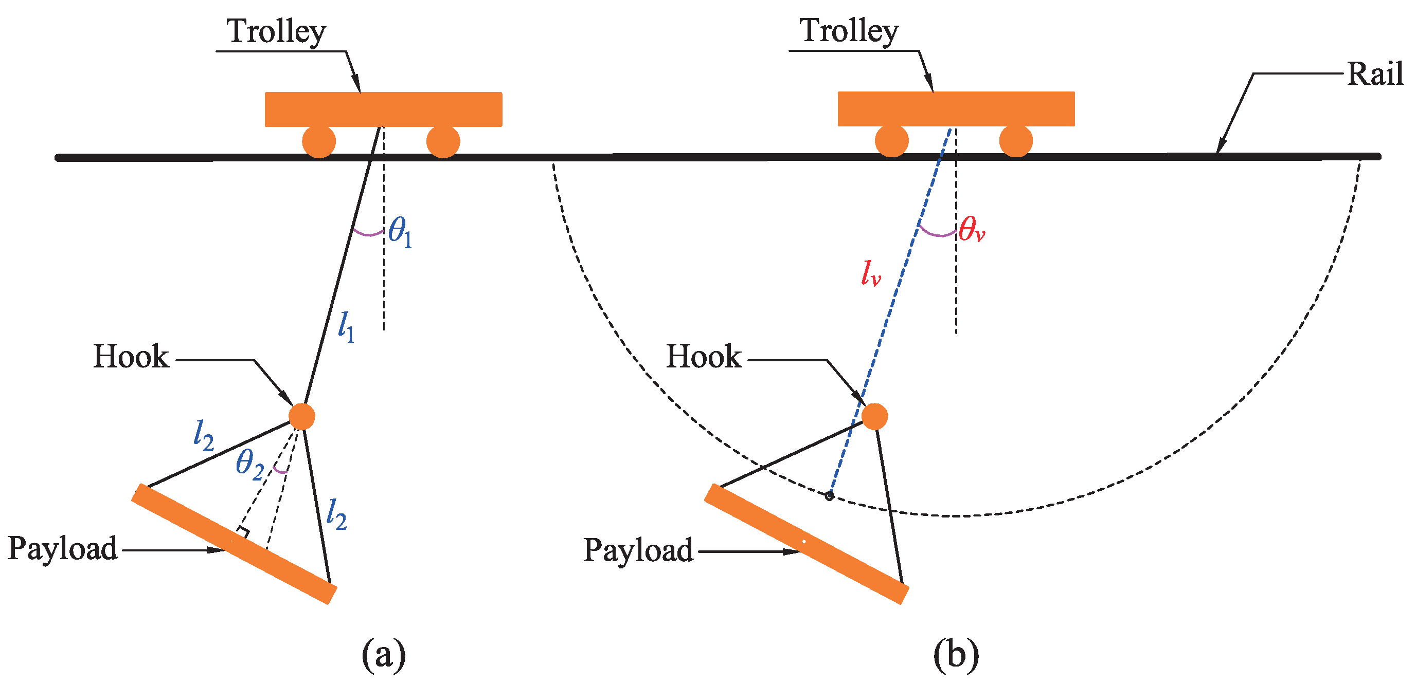
3.1. Concept of the Equivalent Rope Length

First of all, the concept of the equivalent rope length will be proposed. During manual operation, experienced operators can realize the effective control of the crane without the auxiliary of any control system. In detail, the magnitude and direction of the acceleration of the crane system will be determined by the operator to suppress the payload oscillation. In such a case, the control performance completely relies on the experience and intuition of the operator. Therefore, the operator usually needs a long period of training [37]. Further analysis shows that the operator mainly depends on the oscillation law of the payload in the control process. In particular, for the complex double pendulum crane system, the operator also only considers the oscillation law of the payload; in fact, this includes a process in which the complex dynamics of the double pendulum system is transformed into the single pendulum system.
Inspired by the above operation process, the concept of the equivalent rope length is proposed. The double pendulum crane system with the DMP is transformed into the equivalent single pendulum system, as shown in Figure 2b. Where the hook, rigging rope, and DMP as one body are connected to the hoisting mechanism with the equivalent rope length l v , θ v is the corresponding oscillation angle. On this basis, the equivalent single pendulum model is established as follows:
x ˙ = A x + bu
where
x 1 = x ˙ , x 2 = θ v , x 3 = θ ˙ v , u = x ¨ , A = 0 0 0 0 0 1 0 g l v 0 , b = 1 0 1 l v .

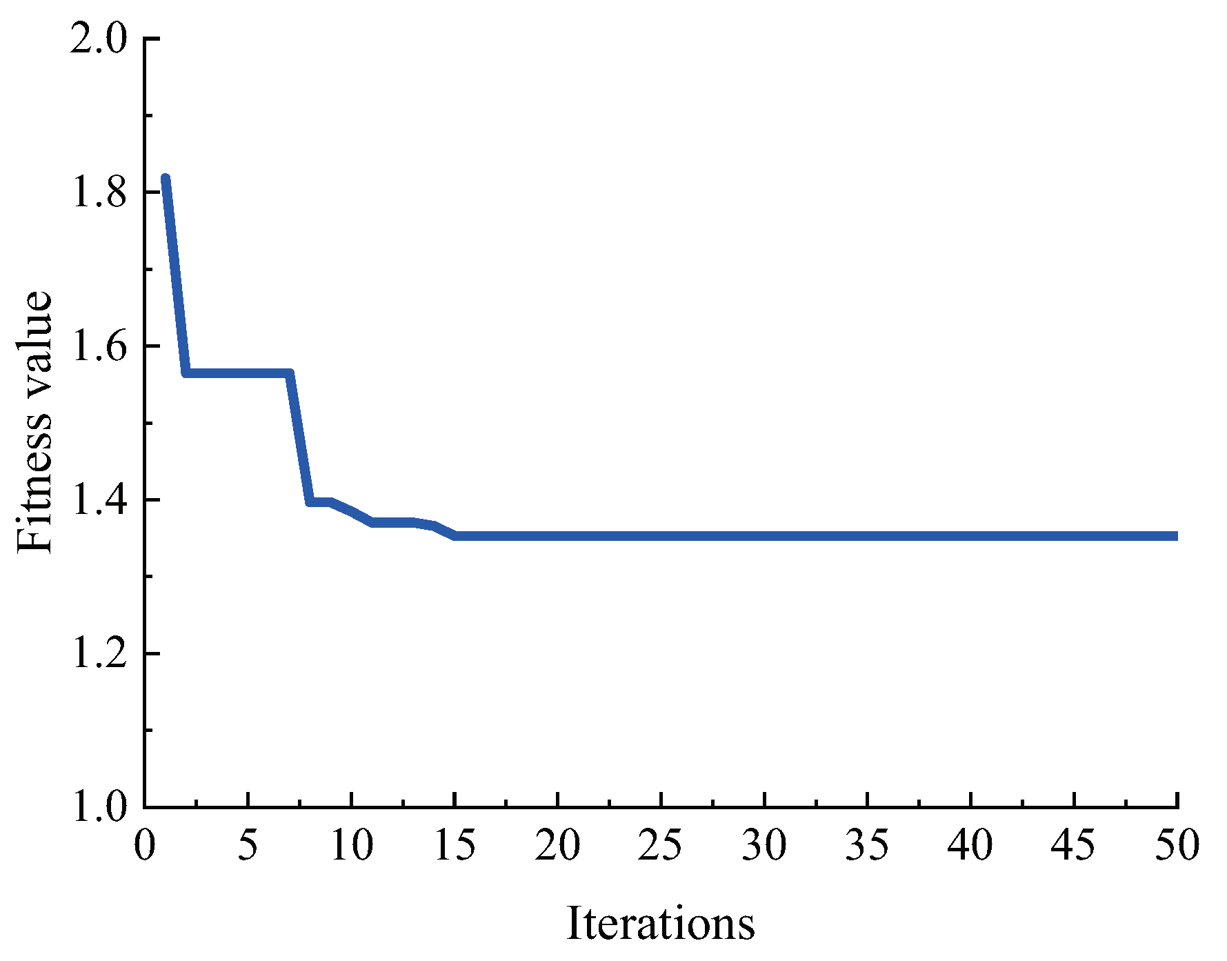
3.2. Anti-Swing Trajectory Planning with the ERL

Furthermore, the anti-swing trajectory planning with the ERL will be proposed. First, the desired velocity during the acceleration process is determined as the maximum velocity of the trolley v m a x , and the desired velocity during the deceleration process is determined as zero. Moreover, in our previous work [35], the trajectory planning including the time optimal control trajectory and the oscillation suppression strategy is proposed to suppress the oscillations of the hook and DMP of the double pendulum crane system, however, the proposed method is also accompanied by a complex structure and a huge amount of calculations, which will increase the performance requirements of the controller. To reduce the complexity and computation of the previous method, considering the above manual operation process and time optimal control trajectory in our previous work, the general function of the anti-swing trajectory planning in the acceleration process is proposed as follows:
F s = x ¨ 1 e t α + e t α + t β s
where x ¨ is the acceleration, which can be solved by x ¨ = v max / ( 2 t α t β ) , based on the phase plane analysis method, the operation time t α and t β can be obtained by t α = α / ω v ,   t β = β / ω v and x ¨ g sin β / 2 + α   = 2 x ¨ g sin ( β / 2 ) , ω v is the oscillation frequency of the equivalent single pendulum system, which can be solved by ω v = l v / g .
Based on the above description, the parameters of the anti-swing trajectory planning with the ERL include t α , t β , v m a x and l v . Further analysis shows that v m a x is determined according to the practical requirement. There is a relation equation between t α and t β . Therefore, the trajectory planning problem is transformed into the calculation problem of t α and l v . To solve this problem, the PSO is proposed with the following introduction.
In PSO, the ranges of t α and l v need be determined first. As shown in Figure 2b, it can be obtained that l v belongs to l 1 , l 1 + l h . Based on the maximum rope length ( l 1 + l h ) of l v , the maximum value of t α can be obtained by T m a x = 2 π ( l 1 + l h ) / g . When the minimum value of t α is chosen as 0.1 s, the range of t α can be determined as 0.1 , T max . Then, in the range of t α and l v , the number of all possible solutions of t α and l v is expressed by S m a x , and the search space of each possible solution is indicated by D m a x -dimensional. In the searching optimization process, t α i + 1 and l v i + 1 and their velocities denoted by v t α i + 1 and v l v i + 1 are updated according to the previous t α i and l v i and their velocities [20,38]:
v t α i + 1 = w v t α i + c 1 r 1 t α i b e s t i t α i + c 2 r 2 t α g b e s t i t α i
v l v i + 1 = w v l v i + c 1 r 1 l v i b e s t i l v i + c 2 r 2 l v g b e s t i l v i
t α i + 1 = t α i + v t α i
l v i + 1 = l v i + v l v i
where i is the number of iterations, t α i b s e t and l v i b e s t are the individual best solutions of t α and l v , respectively, t α g b e s t and l v g b e s t are used to record the global best solution of t α and l v , respectively, c 1 > 0 , c 2 > 0 , r 1 0 , 1 , r 2 0 , 1 , w is adopted to acquire the good solution of t α and l v , which can be solved by w = 2 / ( | 2 φ φ 2 4 φ | ) with ϕ > 4.
To effectively suppress the oscillations of the hook and DMP, the integral of time multiplied absolute error (ITAE) is considered as the fitness function:
ITAE = 0 T t e d t
where e = θ 1 + θ 2 and T is the simulation time. In practical applications, the system is expected to be stable within finite time. Therefore, it is not necessary to integrate to infinity. It is usually to determine a sufficiently large time T and ignore the payload oscillation error of t > T  [39]. On this basis, T = 10 s is adopted. The fitness value of each possible solution of t α and l v is updated in every iteration to finally acquire the optimal solution in the search space area. In order to effectively suppress the oscillation of the DMP, the fitness value should be minimized. During the iterative process, the minimum fitness value is determined by satisfying the condition that there is no residual oscillation angle or a preset number of iterations.
In addition, to satisfy the constraint Equation (5), the penalty procedure, as shown in Algorithm 1, is designed to evaluate the fitness value of each possible solution of t α and l v .
Algorithm 1 Penalty Procedure
if 0 < t β < t α ( i )  then
   Fitness value is chosen as Equation (12)
else
   Fitness value is equal to 10 10
end if
Based on the above description, the solving process of t α and l v utilizing the PSO can be obtained. In detail, the number of iterations and number of possible solutions are chosen as 50 and 50, respectively. c 1 and c 2 are set to be 1.494 and 1.494, respectively. ϕ is selected as 4.1. l h = 0.86 m can be obtained by utilizing the data in Table 1. When l 1 is set to be 1 m, l v = 1.84 m and t α = 1.28 s can be solved, and the fitness value of each iteration is shown in Figure 3.
Finally, considering the maximum and minimum lengths of l 1 in the laboratory crane are 1.30 m and 0.31 m, respectively, the interval of l 1 is set to be 0.1 m, and 10 groups of data for l v and t α can be obtained, respectively. On this basis, utilizing the curve fitting toolbox in MATLAB, the mathematical models of l v and t α with respect to l 1 can be established as follows:
l v = 33.017 l 1 6 169.47 l 1 5 + 352.13 l 1 4 378.1 l 1 3 + 220.61 l 1 2 65.15 l 1 + 8.8059 t α = 62.192 l 1 6 353.78 l 1 5 + 810.34 l 1 4 953.54 l 1 3 + 605.81 l 1 2 195.94 l 1 + 26.22

4. Simulation Verification

In this section, the control performances of the crane system with different fitness functions are compared. In addition, simulations are carried out to verify the effectiveness of the mathematical model of the ERL. The parameters of the crane system are shown in Table 1. v m a x and l v are set to be 0.176 m/s and 1 m, respectively. The iteration numbers and the numbers of particles are chosen as 50 and 50, respectively.

4.1. Simulation 1: Comparison with Other Fitness Functions

Comparative simulations with the integral of absolute error (IAE), integral of square error (ISE) and integral of time square error (ISAE) are carried out. General forms of the IAE, ISE, and ISAE are expressed by IAE = 0 T e d t , ISE = 0 T e 2 d t and ITSE = 0 T t e 2 d t , respectively. The quantitative data of different fitness functions are described in Table 2. where θ m a x is the maximum oscillation angle of the DMP, θ r s is the maximum residual oscillation angle, and t a l l indicates the operation time.
As shown in Table 2, it can be seen that all four fitness functions can be used to solve the l v and t α . Simulation results show that the maximum residual oscillation angle of the DMP and operation time of the ITAE are smaller than those of the IAE, ISE and ITSE. Therefore, the ITAE is considered as a suitable time domain fitness function and no other fitness functions having bigger maximum residual oscillation angle and longer operation time.

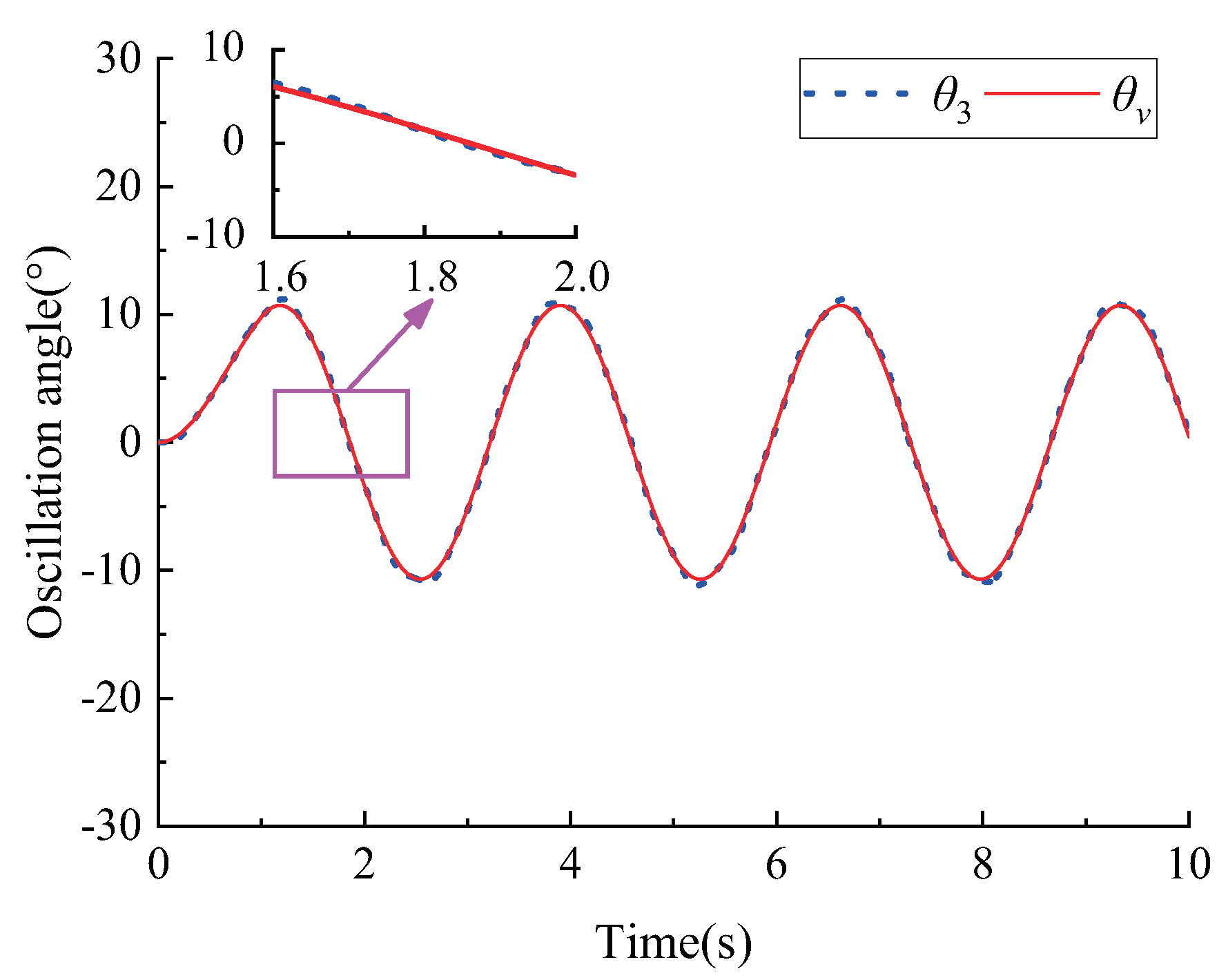
4.2. Simulation 2: Verification the Effectiveness of the Mathematical Model of the ERL

To verify the validity of the mathematical model of the ERL, a set of simulations are carried out. Simulation results under the action of unit pulse excitation are shown in Figure 4. l v is 1.84 m, which can be calculated by Equation (13). Simulation results demonstrate that the oscillation response of the equivalent single pendulum crane system is similar to that of the double pendulum crane with the DMP. On this basis, when the oscillation of the equivalent single pendulum crane system is suppressed, the oscillation of the double pendulum crane system with the DMP will be suppressed.

5. Experimental Verification

Figure 5 shows the self-built experimental platform of the double pendulum bridge crane with the DMP. To be close to industrial applications, the experimental platform is designed by referring to the industrial crane. In detail, the programmable logic controller (PLC) is introduced for the program development, when the inverter is utilized to drive the trolley along the rail. In addition, the wire rope is adopted to connect the hook and the drum of the hoisting mechanism, and its length can be measured by the encoder. Meanwhile, the damping of the wire rope is analyzed [40]. The velocity of the trolley can be measured by an encoder installed at the end of the motor of the trolley. The oscillation angle of the hook and DMP can be measured by the inclination and CMOS camera, respectively. The parameters of the crane system are described in Table 1. The maximum velocity of the trolley is 0.176 m/s. The constant velocity operating time is set to be 6 s. The hoisting rope length is 1 m. In the experiment, referring to the manual operation process, the crane working process is divided into three stages: acceleration, constant velocity, and deceleration. Specifically, when the start button is pressed by the operator, the trolley begins to accelerate based on the designed trajectory. When accelerating to 0.176 m/s, the trolley will operate at the constant velocity of 0.176 m/s for 6 s. Then, when the start button is released, the trolley will start to decelerate according to the planned trajectory.

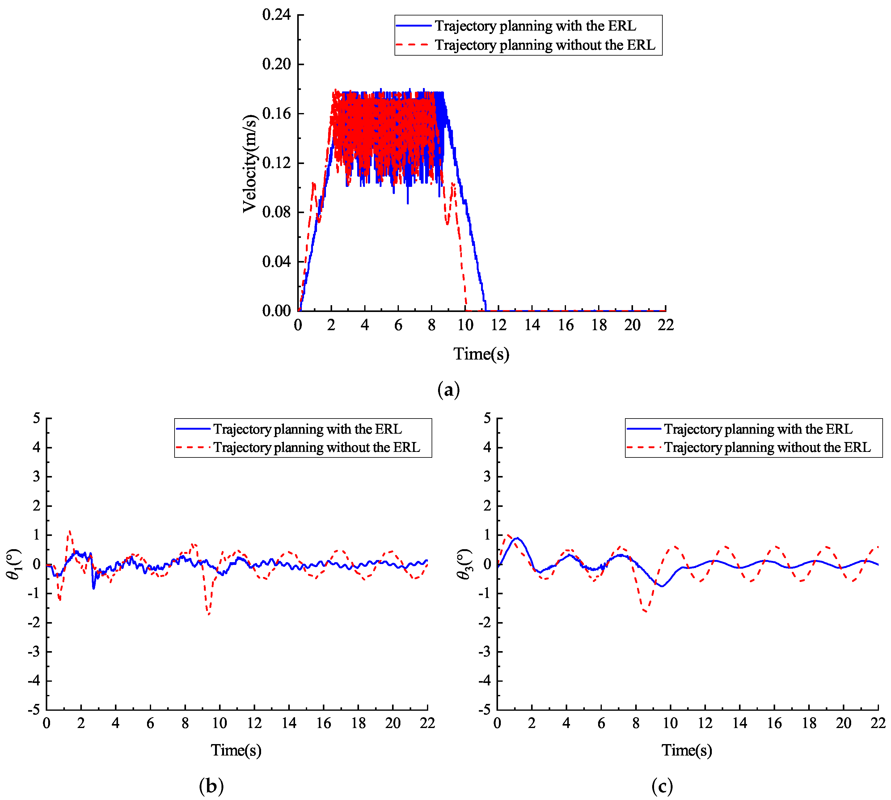
5.1. Experiment 1: Comparison with the Trajectory Planning without the ERL

First, comparative experiments between the proposed trajectory planning with the ERL and the previously proposed method, namely trajectory planning without the ERL [35], are carried out. The general equation of the trajectory method without the ERL can also be expressed as Equation (7), however, more parameters are required to calculate its operation time t α and t β , including the angle between the two rigging ropes, the oscillation angle of the hook and DMP, the oscillation period of the payload, and the quasi-periodicity. A more detailed description of the parameter solution is presented in our previous work [35]. In this paper, it can be solved that t α and t β of the the trajectory planning without the ERL are 0.835 s and 0.329 s, respectively.
Figure 6 depicts the comparative experimental results of the trajectory planning with the ERL and without the ERL. The maximum oscillation angle and the maximum residual oscillation angle of the DMP with the trajectory planning with the ERL are 0.90° and 0.11°, respectively, while the maximum oscillation angle and the maximum residual oscillation angle of 1.63° and 0.48° can be obtained by the trajectory planning without the ERL. A smaller maximum oscillation angle of the DMP will be beneficial to improving the operational safety of the crane system.

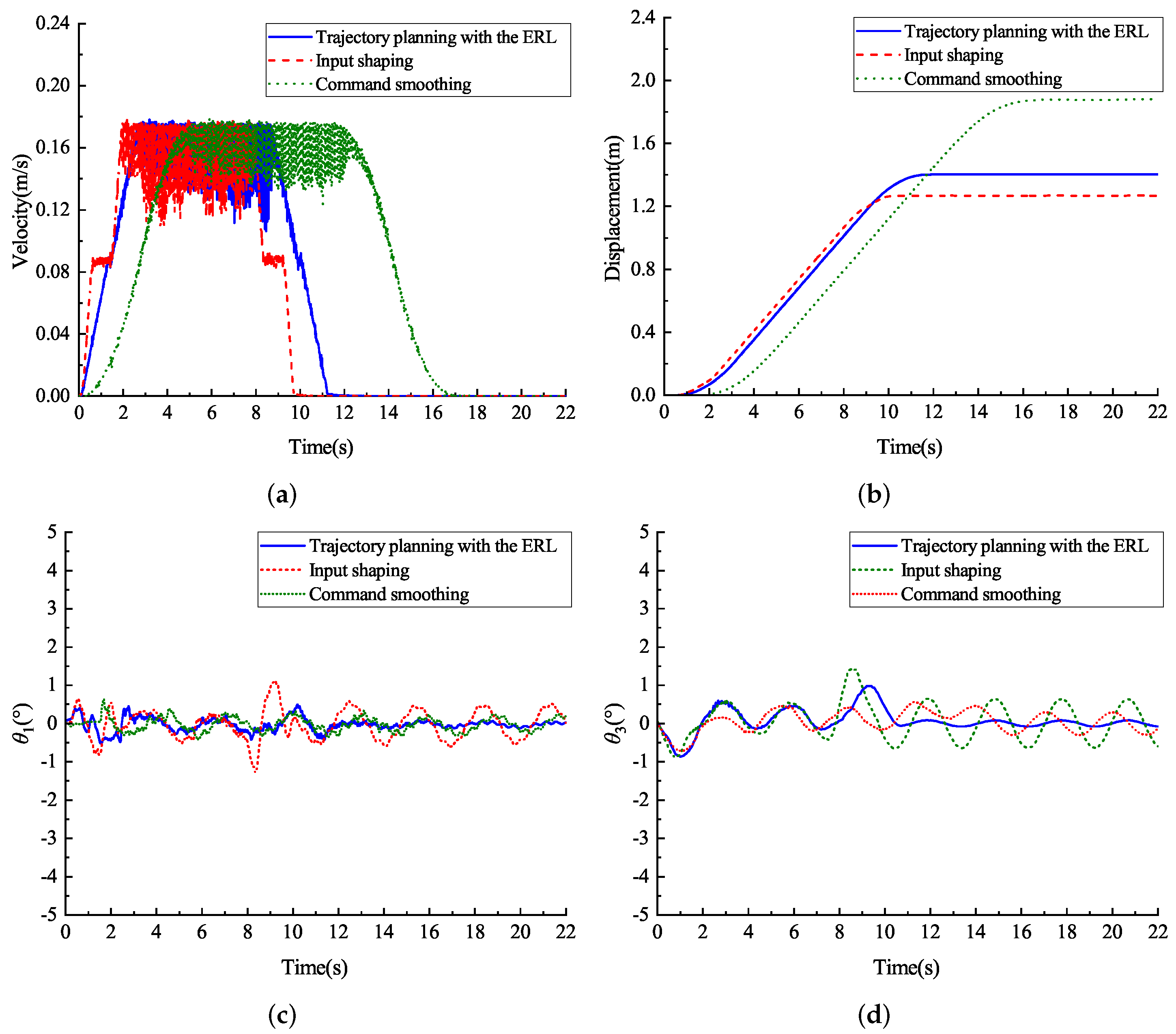
5.2. Experiment 2: Comparison with Existing Methods

Comparative experiments between the proposed method and existing methods such as the input shaping [41] and command smoothing [32] are conducted. General forms of the input shaping and command smoothing are determined by Equations (14) and (15), respectively, as follows:
A j t j = k 1 k 2 A k 1 A k 2 A 1 A 0 τ d 2 τ d 1 τ d 1 + τ d 2
where k i = e π ζ i 1 ζ i 2 , τ d i = π ω n i 1 ζ i 2 , i = 1 , 2 , A = 1 + k 1 1 + k 2 , j = 1 , 2 , 3 , 4 .
h t = a t T 2 , 0 t < T a 2 T t T 2 , T t < 2 T
where a is the gain, T = 2 π 2 π ω 1 ω 1 .
Table 3 illustrates the parameters of the input shaping and command smoothing obtained by Equations (14) and (15).
The contrastive experimental results are described in Figure 7 and Table 4. As shown in Figure 7, the residual oscillation angle of the hook and DMP of the proposed method is close to zero, and the oscillations can be effectively suppressed. Although the response time of the input shaping is the fastest, it also results in the biggest maximum residual oscillation angle, 0.62°, compared with the proposed method, 0.08°, and command smoothing, 0.29°. This is mainly because the acceleration, 0.22 m / s 2 , is bigger than those of the proposed method, 0.072 m / s 2 , and command smoothing, 0.176 m / s 2 . This will inevitably increase the requirements for the system drive capability. In addition, the efficiency of the proposed trajectory planning with the ERL is higher than that of the command smoothing and the translational displacement is smaller. From the quantitative data in Table 4, it can be noted that the efficiency of the proposed controller is improved by (16.88–11.16)/16.88 = 33.9%, when compared with the command smoothing. Meanwhile, the translational displacement of the trajectory planning with the ERL, 1.40 m, which is less than that of the command smoothing, 1.87 m. This means that the time and translational displacement for the deceleration progress of the proposed method are shorter, because the maximum velocity and the constant velocity operating time are the same. In manual operation, shorter deceleration translational displacement will be conducive to improve the positioning accuracy of the payload and the operational safety of the crane system.

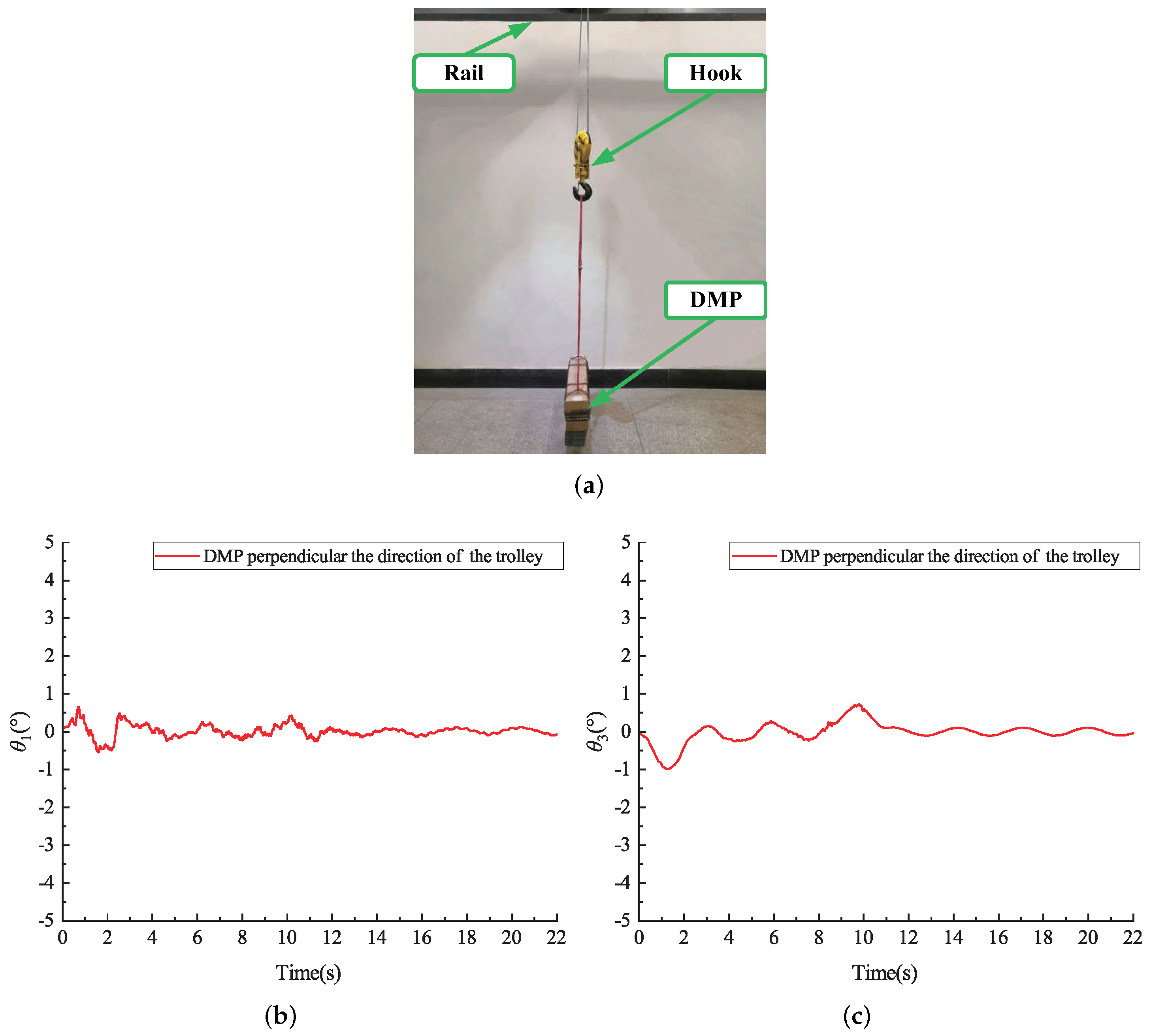
5.3. Experiment 3: Experimental Verification in Different DMP Directions

In practical applications, the direction of the DMP can be divided into two cases: parallel (as shown in Figure 5) and perpendicular (as shown in Figure 8a) to the direction of the trolley. In this part, the experiment is conducted when the DMP is perpendicular to the direction of the trolley. Experimental results are illustrated in Figure 8. Based on the data analysis in Figure 8, showing that when the DMP is perpendicular to the direction of the trolley, the oscillations of the hook and DMP can be suppressed by the proposed method.
The above experiments are carried out with reference to the manual operation process, but the proposed method will also be suitable for automatic control to achieve the point-to-point transportation of the payload. The certain preset target displacement can be transformed into the velocity trajectory of the proposed method.

6. Conclusions

The anti-swing velocity trajectory with the ERL has been proposed for efficient oscillation suppression of the double pendulum bridge crane with the DMP. First, the concept of the ERL is proposed to transform the complex double pendulum bridge crane into the equivalent single pendulum model. On this basis, the anti-swing trajectory planning is designed. Then, the mathematical model of the ERL and parameters of the anti-swing trajectory planning are acquired by utilizing the PSO. Experimental results demonstrate that the oscillations of the hook and DMP can be suppressed and eliminated by the proposed method. Compared with the previous trajectory planning, the controller structure of the proposed method is simpler and the residual oscillation angle is smaller. The implementation of the proposed method for various types of double pendulum crane systems can be explored in the future.

Author Contributions

Conceptualization, Q.W.; methodology, Q.W.; software, Q.W.; validation, Q.W.; formal analysis, Q.W.; investigation, Q.W.; resources, Q.W.; data curation, Q.W.; writing—original draft preparation, Q.W.; writing—review and editing, N.S.; visualization, Q.W.; supervision, N.S. and X.W.; project administration, X.W.; funding acquisition, N.S. and X.W. All authors have read and agreed to the published version of the manuscript.

Funding

This research was funded by the National Natural Science Foundation of China under Grant U1706228 and the China Postdoctoral Science Foundation under Grant 2021M701779.

Institutional Review Board Statement

Not applicable.

Informed Consent Statement

Not applicable.

Data Availability Statement

Not applicable.

Conflicts of Interest

The authors declare no conflict of interest.

Abbreviations

The following abbreviations are used in this manuscript:
ERLEquivalent rope length
DMPDistributed mass payload
PSOParticle swarm optimization
PIDProportional integral derivative

References

  1. Meng, Q.X.; Lai, X.Z.; Yan, Z.; Su, C.Y.; Wu, M. Motion planning and adaptive neural tracking control of an uncertain two-link rigid-flexible manipulator with vibration amplitude constraint. IEEE Trans. Neural Netw. Learn. Syst. 2021, 1–15. [Google Scholar] [CrossRef]
  2. Chen, H.; Sun, N. Nonlinear control of underactuated systems subject to both actuated and unactuated state constraints with experimental verification. IEEE Trans. Ind. Electron. 2019, 67, 7702–7714. [Google Scholar] [CrossRef]
  3. Wu, Q.; Xu, K.X.; Lei, M.Z.; He, X.X. Disturbance-compensation-based continuous sliding mode control for overhead cranes with disturbances. IEEE Trans. Autom. Sci. Eng. 2020, 17, 2182–2189. [Google Scholar] [CrossRef]
  4. Zhang, M.H.; Zhang, Y.F.; Cheng, X.G. An enhanced coupling PD with sliding mode control method for underactuated double-pendulum overhead crane systems. Int. J. Control Autom. Syst. 2019, 17, 1579–1588. [Google Scholar] [CrossRef]
  5. Yang, T.; Sun, N.; Fang, Y.C. Adaptive fuzzy control for a class of MIMO underactuated systems with plant uncertainties and actuator deadzones: Design and experiments. IEEE Trans. Cybern. 2021, 1–14. [Google Scholar] [CrossRef]
  6. Chai, L.; Guo, Q.; Liu, H.; Ding, M.B. Linear active disturbance rejection control for double-pendulum overhead cranes. IEEE Access 2021, 9, 52225–52237. [Google Scholar] [CrossRef]
  7. Zhang, M.H.; Zhang, Y.F.; Ji, B.; Ma, C.H.; Cheng, X.G. Modeling and energy-based sway reduction control for tower crane systems with double-pendulum and spherical-pendulum effects. Meas. Control 2020, 53, 141–150. [Google Scholar] [CrossRef] [Green Version]
  8. O’Connor, W.; Habibi, H. Gantry crane control of a double-pendulum, distributed-mass load, using mechanical wave concepts. Mech. Sci. 2013, 4, 251–261. [Google Scholar] [CrossRef]
  9. Abdel-razak, M.H.; Ata, A.A.; Mohamed, K.T.; Haraz, E.H. Proportional–Integral-derivative controller with inlet derivative filter fine-tuning of a double-pendulum gantry crane system by a multi-objective genetic algorithm. Eng. Optim. 2019, 52, 527–548. [Google Scholar] [CrossRef]
  10. Sun, N.; Fu, Y.; Yang, T.; Zhang, J.Y.; Fang, Y.C.; Xin, X. Nonlinear motion control of complicated dual rotary crane systems without velocity feedback: Design, analysis, and hardware experiments. IEEE Trans. Autom. Sci. Eng. 2020, 17, 1017–1029. [Google Scholar] [CrossRef]
  11. Ouyang, H.M.; Xu, X.; Zhang, G.M. Energy-shaping-based nonlinear controller design for rotary cranes with double-pendulum effect considering actuator saturation. Autom. Constr. 2020, 111, 103054. [Google Scholar] [CrossRef]
  12. Fu, Y.; Sun, N.; Yang, T.; Qiu, Z.H.; Fang, Y.C. Adaptive coupling anti-swing tracking control of underactuated dual boom crane systems. IEEE Trans. Syst. Man Cybern.-Syst. 2021, 1–13. [Google Scholar] [CrossRef]
  13. Sun, N.; Yang, T.; Fang, Y.C.; Wu, Y.M.; Chen, H. Transportation control of double-pendulum cranes with a nonlinear quasi-PID scheme: Design and experiments. IEEE Trans. Syst. Man Cybern.-Syst. 2018, 49, 1408–1418. [Google Scholar] [CrossRef]
  14. Ouyang, H.M.; Deng, X.; Xi, H.; Zhang, G.M.; Mei, L. Novel robust controller design for load sway reduction in double-pendulum overhead cranes. Proc. Inst. Mech. Eng. Part C J. Mech. Eng. Sci. 2019, 233, 4359–4371. [Google Scholar] [CrossRef]
  15. Ouyang, H.M.; Wang, J.; Zhang, G.M.; Mei, L.; Deng, X. Novel adaptive hierarchical sliding mode control for trajectory tracking and load sway rejection in double-pendulum overhead cranes. IEEE Access 2019, 7, 10353–10361. [Google Scholar] [CrossRef]
  16. Shi, H.T.; Li, G.; Ma, X.; Sun, J. Research on nonlinear coupling anti-swing control method of double pendulum gantry crane based on improved energy. Symmetry 2019, 11, 1511. [Google Scholar] [CrossRef] [Green Version]
  17. Ouyang, H.M.; Tian, Z.; Yu, L.L.; Zhang, G.M. Adaptive tracking controller design for double-pendulum tower cranes. Mech. Mach. Theory 2020, 153, 103980. [Google Scholar] [CrossRef]
  18. Qian, D.; Tong, S.; Yang, B.; Lee, S. Design of simultaneous input-shaping-based SIRMs fuzzy control for double-pendulum-type overhead cranes. Bull. Pol. Acad. Sci. Tech. Sci. 2015, 63, 887–896. [Google Scholar] [CrossRef]
  19. Chen, Q.R.; Cheng, W.M.; Gao, L.C.; Fottner, J. A pure neural network controller for double-pendulum crane anti-sway control: Based on Lyapunov stability theory. Asian J. Control 2021, 23, 387–398. [Google Scholar] [CrossRef]
  20. Jaafar, H.I.; Mohamed, Z.; Ahmad, M.A.; Wahab, N.A.; Ramli, L.; Shaheed, M.H. Control of an underactuated double-pendulum overhead crane using improved model reference command shaping: Design, simulation and experiment. Mech. Syst. Signal Proc. 2021, 151, 107358. [Google Scholar] [CrossRef]
  21. Charfeddine, S.; Boudjemline, A.; Ben Aoun, S.; Jerbi, H.; Kchaou, M.; Alshammari, O.; Elleuch, Z.; Abbassi, R. Design of a fuzzy optimization control structure for nonlinear systems: A disturbance-rejection method. Appl. Sci. 2021, 11, 2612. [Google Scholar] [CrossRef]
  22. Hamidi, F.; Aloui, M.; Jerbi, H.; Kchaou, M.; Abbassi, R.; Popescu, D.; Ben Aoun, S.; Dimon, C. Chaotic particle swarm optimisation for enlarging the domain of attraction of polynomial nonlinear systems. Electronics 2020, 9, 1704. [Google Scholar] [CrossRef]
  23. Jaafar, H.I.; Mohamed, Z.; Mohd Subha, N.A.; Husain, A.R.; Ismail, F.S.; Ramli, L.; Tokhi, M.O.; Shamsudin, M.A. Efficient control of a nonlinear double-pendulum overhead crane with sensorless payload motion using an improved PSO-tuned PID controller. J. Vib. Control 2018, 25, 907–921. [Google Scholar] [CrossRef]
  24. Giacomelli, M.; Padula, F.; Simoni, L.; Visioli, A. Simplified input-output inversion control of a double pendulum overhead crane for residual oscillations reduction. Mechatronics 2018, 56, 37. [Google Scholar] [CrossRef] [Green Version]
  25. Ahmad, M.A.; Ismail, R.M.T.R.; Ramli, M.S.; Nasir, A.N.K.; Ghani, N.A.; Noordin, N.H. Comparison of input shaping techniques for sway suppression in a double-pendulum-type overhead crane. In Proceedings of the 2009 Third UKSim European Symposium on Computer Modeling and Simulation, Athens, Greece, 25–27 November 2009; pp. 321–326. [Google Scholar]
  26. Jaafar, H.I.; Mohamed, Z.; Ramli, L.; Abdullahi, A.M. Vibration control of a nonlinear double-pendulum overhead crane using feedforward command shaping. In Proceedings of the 2018 IEEE Conference on Systems, Process and Control (ICSPC), Melaka, Malaysia, 14–15 December 2018; pp. 118–122. [Google Scholar]
  27. Boscariol, P.; Richiedei, D. Robust point-to-point trajectory planning for nonlinear underactuated systems: Theory and experimental assessment. Robot. Comput.-Integr. Manuf. 2018, 50, 256–265. [Google Scholar] [CrossRef]
  28. Chen, H.; Fang, Y.C.; Sun, N. A swing constrained time-optimal trajectory planning strategy for double pendulum crane systems. Nonlinear Dyn. 2017, 89, 1513–1524. [Google Scholar] [CrossRef]
  29. Singhose, W.E.; Towell, S.T. Double-pendulum gantry crane dynamics and control. In Proceedings of the 1998 IEEE International Conference on Control Applications (Cat. No. 98CH36104), Trieste, Italy, 4 September 1998; Volume 2, pp. 1205–1209. [Google Scholar]
  30. Fujioka, D.; Shah, M.; Singhose, W. Robustness analysis of input-shaped model reference control on a double-pendulum crane. In Proceedings of the 2015 American Control Conference (ACC), Chicago, IL, USA, 1–3 July 2015; pp. 2561–2566. [Google Scholar]
  31. Jaafar, H.I.; Mohamed, Z.; Shamsudin, M.A.; Mohd Subha, N.A.; Ramlia, L.; Abdullahi, A.M. Model reference command shaping for vibration control of multimode flexible systems with application to a double-pendulum overhead crane. Mech. Syst. Signal Proc. 2019, 115, 677–695. [Google Scholar] [CrossRef]
  32. Huang, J.; Liang, Z.; Zang, Q. Dynamics and swing control of double-pendulum bridge cranes with distributed-mass beams. Mech. Syst. Signal Proc. 2015, 54, 357–366. [Google Scholar] [CrossRef]
  33. Huang, J.; Xie, X.M.; Liang, Z. Control of bridge cranes with distributed-mass payload dynamics. IEEE-ASME Trans. Mechatron. 2014, 20, 481–486. [Google Scholar] [CrossRef]
  34. Peng, J.H.; Huang, J.; Singhose, W. Payload twisting dynamics and oscillation suppression of tower cranes during slewing motions. Nonlinear Dyn. 2019, 98, 1041–1048. [Google Scholar] [CrossRef]
  35. Wu, Q.X.; Wang, X.K.; Hua, L.; Xia, M.H. Dynamic analysis and time optimal anti-swing control of double pendulum bridge crane with distributed mass beams. Mech. Syst. Signal Proc. 2020, 144, 106968. [Google Scholar] [CrossRef]
  36. Wu, Q.X.; Wang, X.K.; Hua, L.; Xia, M.H. Modeling and nonlinear sliding mode controls of double pendulum cranes considering distributed mass beams, varying roped length and external disturbances. Mech. Syst. Signal Proc. 2021, 158, 107756. [Google Scholar] [CrossRef]
  37. Takemoto, A.; Miyoshi, T.; Terashima, K. Operation assist control system of rotary crane using proposed haptic joystick as man-machine interface. In Proceedings of the 13th IEEE International Workshop on Robot and Human Interactive Communication (IEEE Catalog No. 04TH8759), RO-MAN 2004, Kurashiki, Japan, 22 September 2004; pp. 533–538. [Google Scholar]
  38. Chen, S.; Wang, Y.; Zhang, P.; Su, C.Y. Continuous control strategy of planar 3-linkage underactuated manipulator based on broad neural network. Actuators 2021, 10, 249. [Google Scholar] [CrossRef]
  39. Maiti, D.; Acharya, A.; Chakraborty, M.; Konar, A.; Janarthanan, R. Tuning PID and PIλDδ controllers using the integral time absolute error criterion. In Proceedings of the 2008 4th International Conference on Information and Automation for Sustainability, Colombo, Sri Lanka, 12–14 December 2008; pp. 457–462. [Google Scholar]
  40. Wu, Q.X.; Wang, X.K.; Hua, L.; Xia, M.H. Improved time optimal anti-swing control system based on low-pass filter for double pendulum crane system with distributed mass beam. Mech. Syst. Signal Proc. 2021, 151, 107444. [Google Scholar] [CrossRef]
  41. Fujioka, D.; Singhose, W. Optimized input-shaped model reference control on double-pendulum system. J. Dyn. Sys. Meas. Control 2018, 140, 101004. [Google Scholar] [CrossRef]
Figure 1. Model of the double pendulum bridge crane hoisting the DMP.
Actuators 11 00025 g001
Figure 2. Models of the bridge crane. (a) with the double pendulum, (b) with the equivalent single pendulum.
Actuators 11 00025 g002
Figure 3. Fitness value of each iteration with l 1 = 1 m.
Actuators 11 00025 g003
Figure 4. Oscillation response of the double pendulum crane with the DMP and the equivalent single pendulum crane.
Actuators 11 00025 g004
Figure 5. A double pendulum bridge crane with the DMP.
Actuators 11 00025 g005
Figure 6. Comparative experimental results of the trajectory planning with the ERL and without the ERL. (a) velocity trajectories. oscillation responses of the hook (b) and DMP (c).
Actuators 11 00025 g006
Figure 7. Comparative experimental results of the trajectory planning with the ERL, input shaping, and command smoothing. (a) velocity trajectories, (b) translational displacement, (c) oscillation responses of the hook, (d) oscillation responses of the DMP.
Actuators 11 00025 g007
Figure 8. Experimental results of the DMP parallel and perpendicular to the direction of the trolley. (a) perpendicular direction of the DMP, (b) oscillation responses of the hook, (c) oscillation responses of the DMP.
Actuators 11 00025 g008
Table 1. Parameters of the crane system.
Parameters m 1  (kg) m 2  (kg) l 2  (m) l p  (m)
Values2.50034.1300.8900.465
Table 2. Comparison results of different fitness functions.
Fitness Functions l v  (m) t α  (s) θ max  (°) θ rs  (°) t all  (s)
IAE1.8591.3680.7640.0322.736
ITAE1.8361.2560.8550.0102.581
ISE1.7161.3160.7940.0972.631
ITSE1.7191.3160.7950.0972.632
Table 3. Parameters of the input shaping and command smoothing.
MethodsAmplitude ( m / s 2 )Time (s)
Input shaping A 1 A 2 A 3 A 4 t 1 t 2 t 3 t 4
0.220.220.220.2200.211.361.57
Command smoothingaT
0.1765.44
Table 4. Comparative experimental results.
MethodsOperation Time (s)Translational Displacement (m)
SimulationExperiment
Trajectory planning with the ERL11.161.511.40
Input shaping9.541.371.27
Command smoothing16.882.011.87
Publisher’s Note: MDPI stays neutral with regard to jurisdictional claims in published maps and institutional affiliations.

