Abstract
This paper presents a simple control method on the basis of the trajectory planning for vertical Acrobot to accomplish the control goal of moving the system from the downward initial position (DIP) and steadying the system at the upward target position (UTP). First, for the active link, we frame a trajectory that contains some adjustable parameters. Along the framed trajectory, we can make the active link stabilize at its end angle from its start angle. Furthermore, we change the trajectory parameters to make the passive link also arrive at the zone near the end angle. Next, we devise a PD-based tracking controller to track this planned trajectory. In this way, the vertical Acrobot is swung up to a small zone near the UTP. Then, from the approximate linear model at the UTP, we devise a stabilization controller to stabilize the vertical Acrobot at the UTP. Finally, we implement the simulation to show the validity of the proposed method.
1. Introduction
The rigid manipulator is a mechanical system composed of a connecting link and joint, which is widely used in the real industrial process [1]. The joint without the corresponding control input is called the passive joint [2], and the manipulator with the passive joint is called the underactuated manipulator. The underactuated manipulator has fewer control variables than free degrees [3,4]. Due to its low cost and energy consumption [5,6], this system has received extensive attention and has become a research hotspot in the field of mechanical systems [7,8]. However, its dynamic characteristics are relatively complex, and there are strong coupling relations among the system states, energy, and torque [9,10]. In addition, the lack of some actuators makes the control of such system more challenging.
The underactuated manipulator moving on the vertical plane is called the vertical underactuated manipulator (VUM). Its control problem can be defined as: designing an appropriate controller to move the VUM system from the downward initial position (DIP) and steady it at the upward target position (UTP) [11]. Because the VUM is a second-order nonholonomic system [12], the relationship between the angular velocities and the angles of the links cannot be obtained by direct integration. In addition, the dynamic model of this system does not meet the Brockett’s criteria [13,14], making it difficult to design a smooth state feedback controller to accomplish its control goal [15]. These pose great challenges to the control of the VUM.
However, at the UTP, the approximate linear model (ALM) of the VUM can be calculated, which provides the possibility for accomplishing the stable control of this system [16]. Hence, most scholars adopt the zone method to achieve the system swing-up and stable control goal. This method defines the system as in the balance zone when the linkage states satisfy certain conditions; otherwise, the system is in the swing-up zone [17]. The swing-up controller is usually designed to increase the total energy to move the system to the balance zone, and the common methods include the partial feedback linearization approach, the passivity-based approach, the energy-based approach, and so on. Among them, the energy-based approach constructs an energy-related Lyapunov function, and designs a controller including the states of all links and the total energy, which can not only improve the success rate of entering the balance zone, but also shorten the time required for the system to enter the balance zone. Then the stabilization controller on the basis of the ALM at the UTP [18] is designed in the balance zone to accomplish the stable control goal of the VUM [19,20], and the main methods include the LQR approach, the linear matrix inequality approach, etc.
Although the zone control method is sometimes effective, the following issues need to be addressed: (1) if the limit range of the state conditions is too small, these conditions are hard to meet [21,22,23], resulting in difficulty moving the system smoothly to the balance zone via a swing-up controller [24]; if the limit range is large, the torque will occur at a sudden moment [25], and even the stabilization controller cannot accomplish the stabilization of the VUM system when the controller is switched [26]. (2) Due to the complex coupling relations among the linkage states, energy, and torque [27], the swing-up controller is prone to singular phenomena, which increases the complexity of a controller design [28,29].
The vertical two-link underactuated manipulator includes the Pendubot (with first active joint) [30] and Acrobot (with second active joint) [31], which are often used to verify the validity of the method for the nonlinear system. In this paper, taking the vertical Acrobot as the research object, we created a simple control strategy on the basis of the trajectory planning method to solve the problems in the zone control method and accomplish the system control goal. Firstly, a trajectory with adjustable parameters was framed for the active link. By analyzing the trajectory characteristics, the active link can be moved from its start angle, and be stabilized at the end angle along the planned trajectory. Due to the state coupling relationship, the parameters in the trajectory were adjusted to ensure the passive link also arrived at the zone near its target position. Then, a PD-based tracking controller was devised to track the planned trajectory, swinging the system up to a small zone near the UTP. When the linkage states satisfy the switching criteria, a stabilization controller was designed to stabilize the system at the UTP, thus realizing the control goal of the vertical Acrobot. Finally, the simulation result shows the validity of the proposed approach.
The main innovations of this paper are as follows:
(1) In contrast to existing methods, the vertical Acrobot is easily swung up from the DIP to a small zone near the UTP by adjusting the parameters in the planned trajectory and tracking this trajectory.
(2) Compared with the energy-based swing-up controller, a simpler PD-based tracking controller without the singular value is devised.
(3) Unlike most methods that are only suitable for a particular system, the method proposed in this paper is also applicable to the VUM with multiple links and passive joints.
2. System Dynamic Model and Control Idea
Figure 1 displays the model of the vertical Acrobot moving on the vertical plane. The variables in Figure 1 are defined in Table 1.
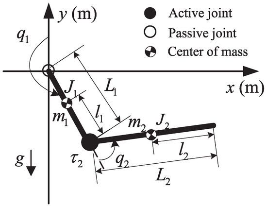
Figure 1.
Model of the vertical Acrobot.

Table 1.
Definition of the variables in Figure 1.
We obtain the dynamic model of the vertical Acrobot by utilizing the Euler–Lagrange method:
where and are the angular accelerations of the passive and active link. , , and are shown as follows:
where and represent the angles of the passive link and active link, and and are the angular velocities of the passive and active link.
Let , then the state space equation of the vertical Acrobot is rewritten as
where
and
For the vertical Acrobot, because its head joint has no driving device, resulting in the lack of corresponding control torque, it is difficult to directly control the passive link to accomplish its control goal. Generally, by increasing the total energy of the system, the underactuated system can be swung up to the zone near the target position. However, the coupling condition among the control torque, system energy, and linkage states makes the controller on the basis of the energy approach prone to the singularity in the design process. Although some scholars have proposed avoiding the singularity by adjusting controller parameters, there are also other problems, such as complex controller design and difficult controller parameter selection.
In view of these problems, the purpose of this paper is to propose a simple control method, which does not need to consider the singularity of the control process, and can easily adjust the design parameters. Combined with the control goal of the active link, by means of the trajectory planning method, it is convenient to frame a trajectory for the active link. The design of the trajectory is the key of the swing-up motion of Acrobot, which is related to whether the control goal of the active link can be realized. The framed trajectory of the active link must meet the following requirements: (1) The initial and target position of the trajectory must be consistent with the start and end angle of the active link. (2) The angular velocity trajectory obtained by deriving the planned angle trajectory should satisfy that the values at the initial and terminal time are zero. In this way, by tracking the trajectory satisfying the above conditions, the active link can be moved directly from the start angle and be stabilized at its end angle, thus realizing the control goal of the active link.
Although the control goal of the active link can be easily realized through the tracking control, the motion state of the passive link is different when tracking a different trajectory of the active link, which may result in the failure of realizing the system swing-up control goal. However, from (1), there are coupling relations among the angular acceleration, angular velocity, and angle of each link. So, we can indirectly control the passive link by adjusting the state of the active link. Hence, we need to add some adjustable parameters to the planned trajectory for the active link. By changing these parameters, the states of the active link and passive link can be changed. In this way, it is theoretically possible to swing the VUM up to the UTP. In addition, from the aspect of controller design, it is necessary to devise a controller to track the framed trajectory for the active link. The controller is only connected to the state of the active link; thus, the tracking controller on the basis of the trajectory planning method does not have the singular phenomenon. Next, we give the specific process of the trajectory planning and controller design.
3. Trajectory Planning
From the control goal of the vertical Acrobot, we obtain the end angle of the active link, denoted as . If the start angle is given, according to and , an angle trajectory is framed with adjustable parameters for the active link as follows:
where , and .
Remark: The angle trajectory (9) is a curve related to the time and adjustable parameters , , and . The selection of these adjustable parameters is crucial to the successful realization of the system control goal. We can reduce the fluctuations of the trajectory by increasing and shorten the time of approaching the target position by increasing and . Due to the few parameters in the trajectories designed in this paper, the appropriate trajectory parameters can be selected by attempts easily, swinging the vertical Acrobot up to a small zone near the target position quickly by the tracking control.
Taking the derivation of (9) obtains the angular velocity trajectory:
The angular acceleration trajectory is also obtained
From (9) and (10), we can obtain the initial position and velocity () and target position and velocity () of the planned trajectory:
which are consistent with the start and end state of the active link.
In addition, from (11), is bounded, which means that (9) and (10) are uniformly continuous. So, combined with (12), regardless of the values of the parameters, the active link can always converge to its end state along the designed trajectory (9) when .
From (10) and (11), when tracking the trajectory (9) with different , and , the motion state of each link is different. Thus, we can adjust the linkage state by changing the parameters , and . It should be emphasized that there are only three parameters in the trajectory designed in this paper, and the parameter rectification is relatively simple.
The planned angle trajectory and corresponding angular velocity trajectory are shown as Figure 2. Along the planned system’s angle trajectory, the active link can always arrive at its end angle with a zero angular velocity at a certain time. At this moment, two links of the vertical Acrobot are straightened, as shown in Figure 3a. However, generally, it is difficult to ensure that the passive link also reaches its end angle with a zero angular velocity while the active link follows the trajectory (9). After the active link reaches its end state, the endpoint of the vertical Acrobot will move along the circle with the passive joint as the center and the radius . From (10) and (11), the state of the active link is related to the adjustable parameters. So, based on (1), if we choose different parameters, the state of the active link and the passive link will also be different. Therefore, we adjust the parameters of the planned trajectory to make the states of the active link and the passive link satisfy the following conditions:
where , and are small positive numbers, and is a function that can obtain the remainder after division of a by b. At this time, along the planned angle trajectory, the vertical Acrobot is moved from the DIP to a small zone near the UTP, as shown in Figure 3b.
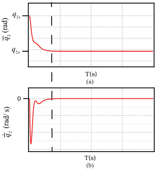
Figure 2.
Planned trajectory: (a) angle; (b) angular velocity.
Figure 3.
Motion-process analysis: (a) case 1; (b) case 2.
It should be emphasized that the trajectory model designed in this section is also applicable to the multi-link VUM. We can design a similar trajectory for each active link of the multi-link VUM and then adjust the trajectory parameters to make all links move to the target position simultaneously.
4. Control Scheme
In this section, we design a PD-based tracking controller to track the planned angle trajectory, swinging the vertical Acrobot to a small zone near the UTP. Then, we design a pole-assignment-based stabilization controller to realize the system stable control.
4.1. Tracking Controller Design
We define the trajectory tracking error as and . Based on and , the candidate Lyapunov function is constructed as
where .
The derivative of V is
We design the PD-based trajectory tracking controller as
where .
Because is a positive-definite symmetric matrix, is also a positive definite symmetric matrix. From (3) and (8), is the main diagonal element in , so . Therefore, there is no singular value in the tracking controller . Compared with the existing swing-up controller, the PD-based tracking controller based on the planned trajectory is simpler without complicated formula derivations.
4.2. Stabilization Controller Design
Based on the ALM at the UTP, we designed a pole-assignment-based stabilization controller [32] to make the vertical Acrobot stabilize at the UTP.
Then, for the linear system (18), we designed the stabilization controller as follows:
where K is the controller gain.
The PLACE function in Matlab is used to solve the value of K, ensuring is a Hurwitz matrix. In this way, the stabilization controller (19) enables the closed loop system (20) to be stable; all links converge to their end states eventually. The vertical Acrobot is stabilized at the UTP finally.
To sum up, the control method in this paper can be divided into two stages:
- 1
- Tracking control stage: Swinging the vertical Acrobot to a small zone near the UTP by using the PD-based tracking controller;
- 2
- Stable control stage: Stabilizing the vertical Acrobot at the UTP by using the pole-assignment-based stabilization controller.
The controller is switched from the PD-based tracking controller to the pole-assignment-based stabilization controller when (13) is satisfied.
5. Simulation Result
In this section, we demonstrate the validity of the presented method through simulation. During the simulation process, we used a high-precision solver and set a small tolerance to increase the accuracy of the simulation as much as possible.
The structural parameters of the vertical Acrobot are listed as follows:
From the control goal, we know the system start state and end state as:
where and are integers.
First, we randomly give a set of trajectory parameters as follows:
Set the closed-loop poles as and . Then, the gain of (19) is calculated through the PLACE function:
The simulation result with the parameters (23) is shown in Figure 4. The control goal of the system is not achieved by tracking the trajectory with this set of parameters. At about 2 s, . That is, the active link is moved to the end angle from its start angle, and its angular velocity becomes zero. However, at this point, are in an unstable state, and the passive link does not arrive at the end state. The states switching conditions (13) are not met, causing the controller to be unable to switch to the stabilization controller. Although we can set as a larger value to relax the conditions (13), this will result in sudden torque change switching the controller (16) to the controller (19). Thus, we mainly adjust the trajectory parameters to make the state conditions (13) hold.
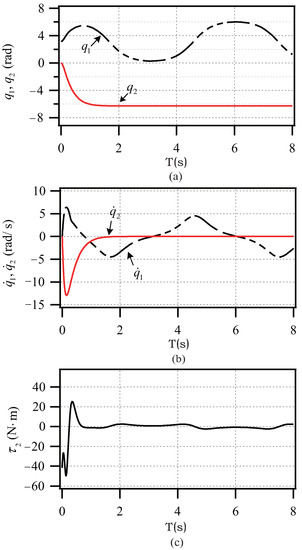
Figure 4.
Simulation results with (23): (a) angle; (b) angular velocity; (c) torque.
In order to make the states of all links meet the conditions (13), combined with the simulations, we select an appropriate set of parameters by attempts
By tracking the trajectory with the parameter (26), the conditions (13) are satisfied. In this way, the controller is switched to the stabilization controller from the PD-based tracking controller.
The parameters in (16), (13), and (19) are the same as those in (24). The simulation result with the parameter (26) is shown in Figure 5. At about 4 s, and . That is, all links are moved to their end angles from their start angles, their angular velocities become zero, and the torque converges to zero. The endpoint trajectory in Figure 6 shows that the endpoint is swung up from the DIP, is stabilized at the UTP finally, and the system control goal is realized. Compared with the control effect (7 s, 180 ) in [11], although the maximum torque of the presented method increases, the time to accomplish the control goal is significantly shortened. More importantly, compared with the method in [11], the method in this paper has no complicated formula derivation process and is simpler with less calculation. In addition, different from the traditional zone method in [28], the proposed method can easily swing the vertical Acrobot up directly to the small zone near the UTP by tracking the planned trajectory with suitable parameters, and there is no singular value in the tracking controller during the control process, which also demonstrates the simplicity and superiority of our method.
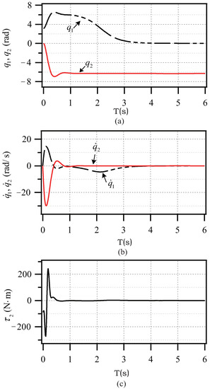
Figure 5.
Simulation results with (26): (a) angle; (b) angular velocity; (c) torque.
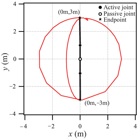
Figure 6.
Endpoint trajectory.
6. Conclusions
This paper presented a simple control strategy on the basis of the trajectory planning method for the vertical Acrobot to accomplish the swing-up and stable control goal. First, the angle trajectory from its start angle to its end angle was framed for the active link, and the trajectory included some adjustable parameters. Then, the PD-based tracking controller was devised to track the framed trajectory. The state switching conditions were met by adjusting the parameters in the planned trajectory. Next, a stabilization controller was devised to steady the system at the UTP. Finally, the simulation result showed the validity of our method.
It is easy to swing the vertical Acrobot up from the DIP to a small zone near the UTP by using the proposed method. Compared with the existing methods, the PD-based tracking controller is simpler without the singular value. Moreover, the trajectory model in this paper is universal and can be directly applied to the multilink VUM. In the future, we will combine some intelligent methods to study the control strategy of the manipulator with multiple links and multiple passive joints. In addition, we plan to build an experimental platform of the underactuated manipulator to further verify the effectiveness of the proposed control strategy through experiments by comprehensively considering the external disturbance, measurement noise, parameter disturbance, and other influence factors.
Author Contributions
Conceptualization, J.S. and X.L.; methodology, L.W.; validation, L.W. and S.C.; formal analysis, L.W.; investigation, L.W.; writing—original draft preparation, L.W. and S.C.; writing—review and editing, P.Z.; supervision, J.S.; project administration, X.L.; funding acquisition, X.L. All authors have read and agreed to the published version of the manuscript.
Funding
This work was supported by: (i) National Natural Science Foundation of China (61773353 and 61873348); (ii) Hubei Provincial Natural Science Foundation of China (2015CFA010); (iii) 111 Project (B17040).
Institutional Review Board Statement
Not applicable.
Informed Consent Statement
Not applicable.
Data Availability Statement
Not applicable.
Conflicts of Interest
The authors declare no conflict of interest.
Abbreviations
The abbreviations used in our paper are as follows:
| DIP | Downward initial position |
| UTP | Upward target position |
| VUM | Vertical underactuated manipulator |
| ALM | Approximate linear model |
References
- Zhang, T.; Zhang, W.J.; Gupta, M.M. An underactuated self-reconfigurable robot and the reconfiguration evolution. Mech. Mach. Theory 2018, 124, 248–258. [Google Scholar] [CrossRef]
- Wang, F.; Qian, Z.; Yan, Z.; Yuan, C.; Zhang, W. A novel resilient robot: Kinematic analysis and experimentation. IEEE Access 2020, 8, 2885–2892. [Google Scholar] [CrossRef]
- He, B.; Liu, Y.J. Underactuated robotics: A review. Int. J. Adv. Robot. Syst. 2019, 16, 1–29. [Google Scholar] [CrossRef] [Green Version]
- Wang, L.J.; Lai, X.Z.; Zhang, P.; Wu, M. A unified and simple control strategy for a class of n-link vertical underactuated manipulator. ISA Trans. 2021. [Google Scholar] [CrossRef]
- Liu, Y.; Yu, H.N. A survey of underactuated mechanical systems. IET Control Appl. 2013, 7, 921–935. [Google Scholar] [CrossRef] [Green Version]
- Wu, J.D.; Wang, Y.W.; Ye, W.J.; Su, C.-Y. Control strategy based on Fourier transformation and intelligent optimization for planar pendubot. Inf. Sci. 2019, 491, 279–288. [Google Scholar] [CrossRef]
- Yang, X.B.; Zheng, X.L. Swing-up and stabilization control design for an underactuated rotary inverted pendulum system: Theory and experiments. IEEE Trans. Ind. Electron. 2018, 65, 7229–7238. [Google Scholar] [CrossRef]
- Wang, L.J.; Lai, X.Z.; Zhang, P.; Wu, M. Single controller design based on integrated trajectory for three-link vertical underactuated manipulators with first active joint. Int. J. Control 2021. [Google Scholar] [CrossRef]
- Mathis, F.B.; Jafari, R.; Mukherjee, R. Impulsive actuation in robot manipulators: Experimental verification of pendubot swing-up. IEEE/ASME Trans. Mechatron. 2014, 19, 1469–1474. [Google Scholar] [CrossRef]
- Zhang, A.C.; Qiu, J.L.; Yang, C.D.; He, H.B. Stabilization of underactuated four-link gymnast robot using torque-coupled method. Int. J. Non Linear Mech. 2015, 77, 299–306. [Google Scholar] [CrossRef]
- Zhang, A.C.; She, J.H.; Lai, X.Z.; Wu, M. Global stabilization control of acrobot based on equivalent-input-disturbance approach. IFAC Proc. Vol. 2011, 44, 14596–14601. [Google Scholar] [CrossRef]
- Gao, X.S.; Yan, L.; Gerada, C. Modeling and analysis in trajectory tracking control for wheeled mobile robots with wheel skidding and slipping: Disturbance rejection perspective. Actuators 2021, 10, 222. [Google Scholar] [CrossRef]
- Brockett, R.W. Asymptotic stability and feedback stabilization. Differ. Geom. Control Theory 1983, 27, 181–191. [Google Scholar]
- Oriolo, G.; Nakamur, Y. Control of mechanical systems with second order nonholonomic constraints: Underactuated manipulator. In Proceedings of the 30th IEEE Conference on Decision and Control, Brighton, UK, 11–13 December 1991; pp. 2398–2403. [Google Scholar]
- Banavar, R.N.; Mahindrakar, A.D. A non-smooth control law and timeoptimality notions for the acrobot. Int. J. Control 2005, 78, 1166–1173. [Google Scholar] [CrossRef]
- Xin, X.; Liu, Y.N. Reduced-order stable controllers for two-link underactuated planar robots. Automatica 2013, 49, 2176–2183. [Google Scholar] [CrossRef]
- Jafari, R.; Mathis, F.B.; Mukherjee, R.; Khalil, H.K. Enlarging the region of attraction of equilibria of underactuated systems using impulsive inputs. IEEE Trans. Control Syst. Technol. 2016, 24, 334–340. [Google Scholar] [CrossRef]
- Horibe, T.; Zhou, B.; Hara, S.; Tsubakino, D. Quantitative measure for nonlinear unstable systems based on the region of attraction and its application to designing parameter optimization-inverted pendulum example. Adv. Robot. 2018, 32, 399–410. [Google Scholar] [CrossRef]
- Horibe, T.; Sakamoto, N. Nonlinear optimal control for swing up and stabilization of the acrobot via stable manifold approach: Theory and experiment. IEEE Trans. Control Syst. Technol. 2019, 27, 2374–2387. [Google Scholar] [CrossRef]
- Yaman, U.; Silik, Y. Control of rotary inverted pendulum by using on-off type of cold gas thrusters. Actuators 2020, 9, 95. [Google Scholar]
- Izumi, K.; Kamada, Y.; Ichida, K. A switching control of underactuated manipulators by introducing a definition of monotonically decreasing energy. In Proceedings of the 2008 6th IEEE International Conference on Industrial Informatics, Daejeon, Korea, 13–16 July 2008; pp. 383–388. [Google Scholar]
- Eom, M.; Chwa, D. Robust swing-up and balancing control using a nonlinear disturbance observer for the pendubot system with dynamic friction. IEEE Trans. Robot. 2015, 31, 331–343. [Google Scholar] [CrossRef]
- Lai, X.Z.; Zhang, A.C.; She, J.H.; Wu, M. Motion control of underactuated three-link gymnast robot based on combination of energy and posture. IET Control Theory Appl. 2011, 5, 1484–1493. [Google Scholar] [CrossRef]
- Liu, Y.N.; Xin, X. Global motion analysis of energy-based control for 3-link planar robot with a single actuator at the first joint. Nonlinear Dyn. 2017, 88, 1749–1768. [Google Scholar] [CrossRef]
- Xin, X.; Kaneda, M. Analysis of the energy-based swing-up control of the Acrobot. Int. J. Robust Nonlinear Control 2010, 17, 1503–1524. [Google Scholar] [CrossRef]
- Mobayen, S. Design of LMI-based sliding mode controller with an exponential policy for a class of underactuated systems. Complexity 2016, 21, 117–124. [Google Scholar] [CrossRef]
- Fantoni, I.; Lozano, R.; Spong, M.W. Energy based control of the Pendubot. IEEE Trans. Autom. Control 2000, 45, 725–729. [Google Scholar] [CrossRef] [Green Version]
- Lai, X.Z.; She, J.H.; Yang, S.X.; Wu, M. Comprehensive unified control strategy for underactuated two-link manipulators. IEEE Trans. Syst. Man Cybern. Part B Cybern. 2009, 39, 389–398. [Google Scholar]
- Lai, X.Z.; Zhang, A.C.; Wu, M.; She, J.H. Singularity-avoiding swing-up control for underactuated three-link gymnast robot using virtual coupling between control torques. Int. J. Robust Nonlinear Control 2015, 25, 207–221. [Google Scholar] [CrossRef]
- Wang, L.J.; Lai, X.Z.; Zhang, P.; Wu, M. A control strategy based on trajectory planning and optimization for two-link underactuated manipulators in vertical plane. IEEE Trans. Syst. Man Cybern. Syst. 2021. [Google Scholar] [CrossRef]
- Baek, I.; Kim, H.; Lee, S.; Hwang, S.; Shin, K. Swing-up control design for spring attatched passive joint acrobot. Int. J. Precis. Eng. Manuf. 2020, 21, 1865–1874. [Google Scholar] [CrossRef]
- Zhu, L.; Qiu, J.; Karimi, H.R. Region stabilization of switched neural networks with multiple modes and multiple equilibria: A pole assignment method. IEEE Trans. Neural Netw. Learn. Syst. 2020, 31, 3280–3293. [Google Scholar] [CrossRef]
Publisher’s Note: MDPI stays neutral with regard to jurisdictional claims in published maps and institutional affiliations. |
© 2021 by the authors. Licensee MDPI, Basel, Switzerland. This article is an open access article distributed under the terms and conditions of the Creative Commons Attribution (CC BY) license (https://creativecommons.org/licenses/by/4.0/).