
Modeling and Experiments of an Annular Multi-Channel Magnetorheological Valve

Abstract
:1. Introduction
2. Design of Annular Multi-Channel MR Valve
2.1. Working Principle and Structure
2.2. Magnetic Circuit Design
2.3. Pressure Drop Analysis of Annular Multi-Channel MR Valve
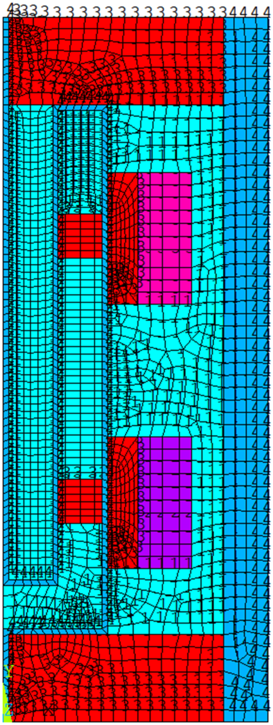
3. Numerical Analysis Results and Discussion
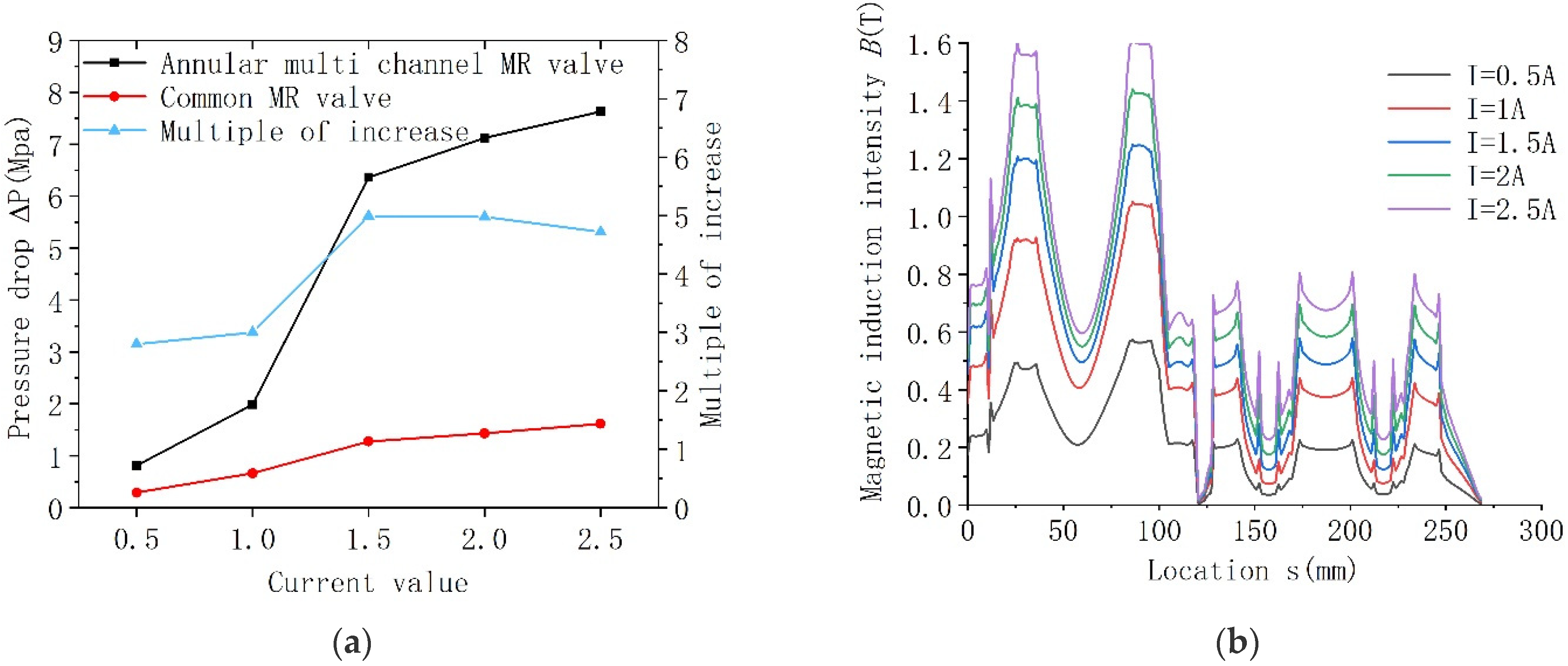
3.1. Influence of Current on Pressure Drop Performance of Annular Multi-Channel MR Valve
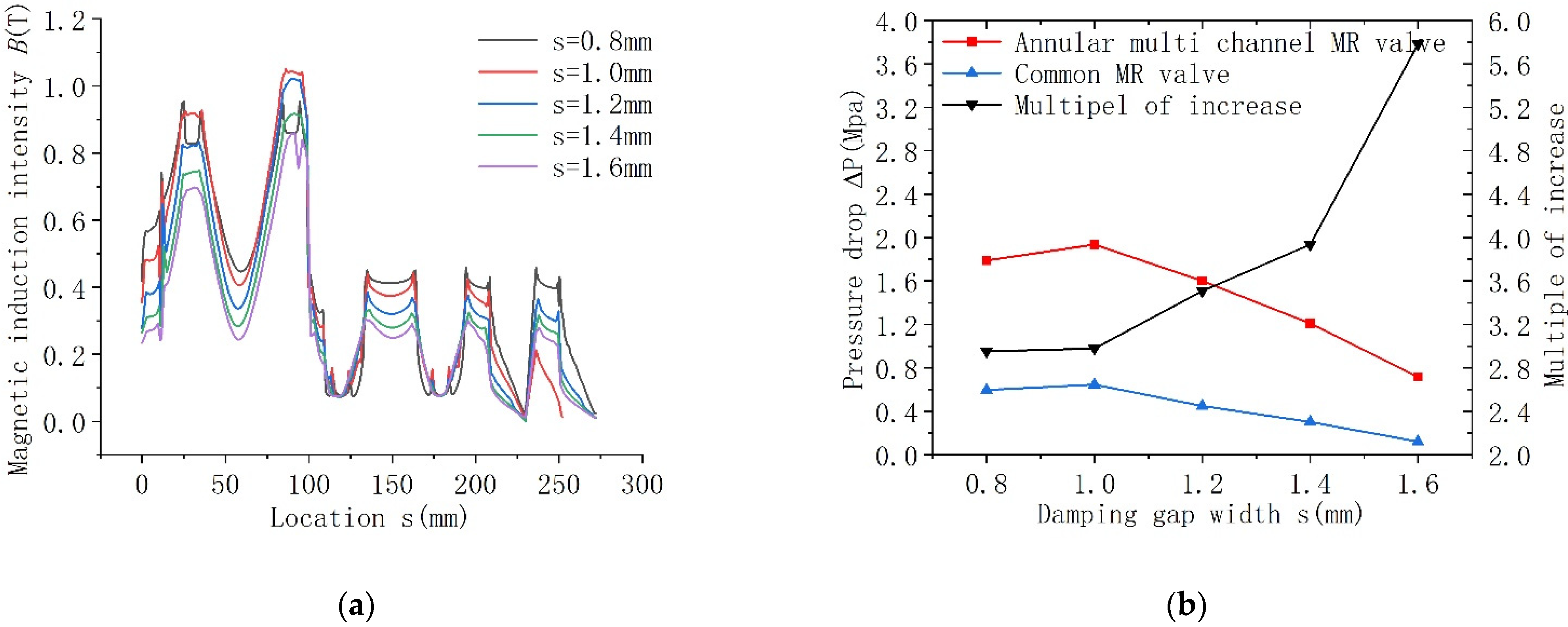
3.2. Influence of Damping Gap Width on Pressure Drop Performance of Annular Multi-Channel MR Valve
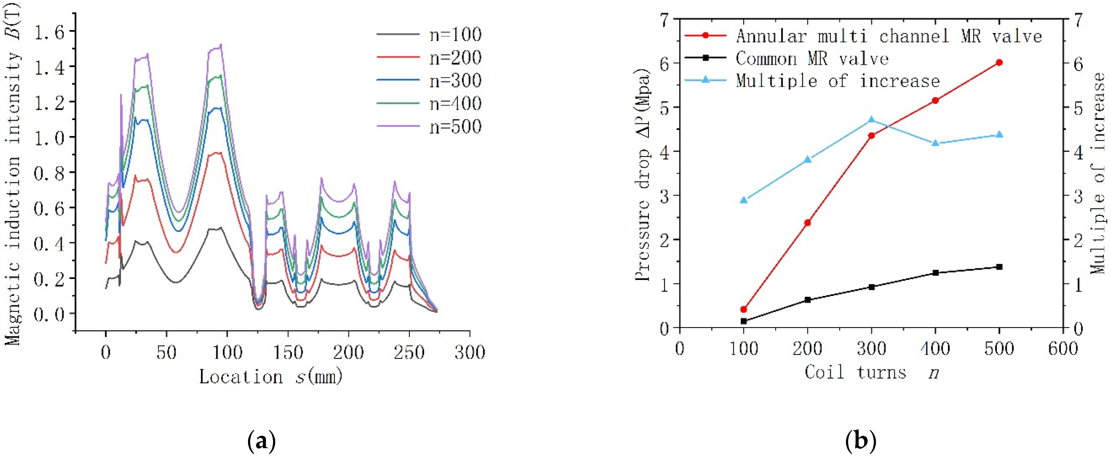
3.3. Influence of Coil Turns on Pressure Drop Performance of Annular Multi-Channel MR Valve
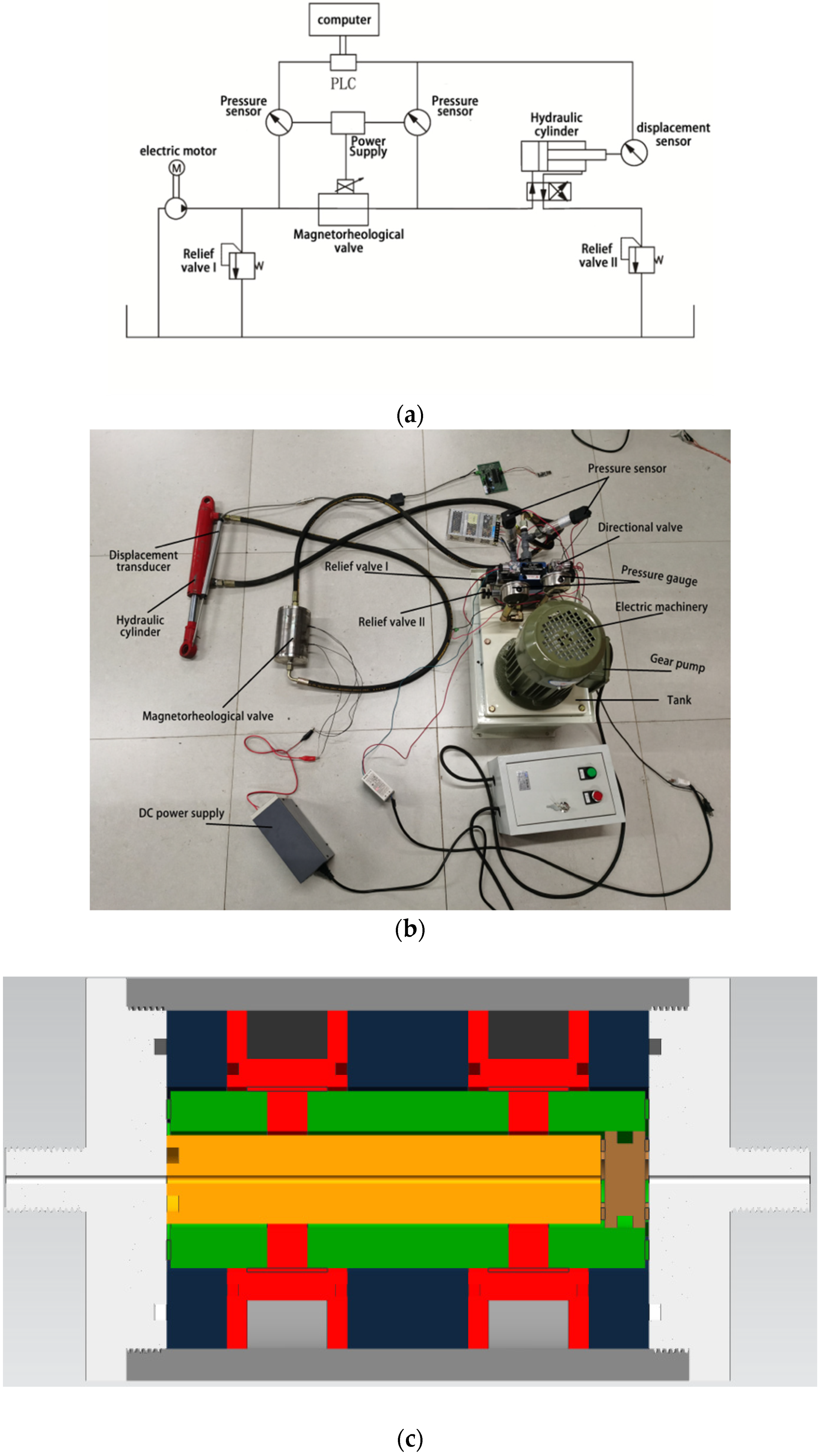
4. Experimental Study on Annular Multi-Channel MR Valve
5. Analysis and Discussion of Experimental Results
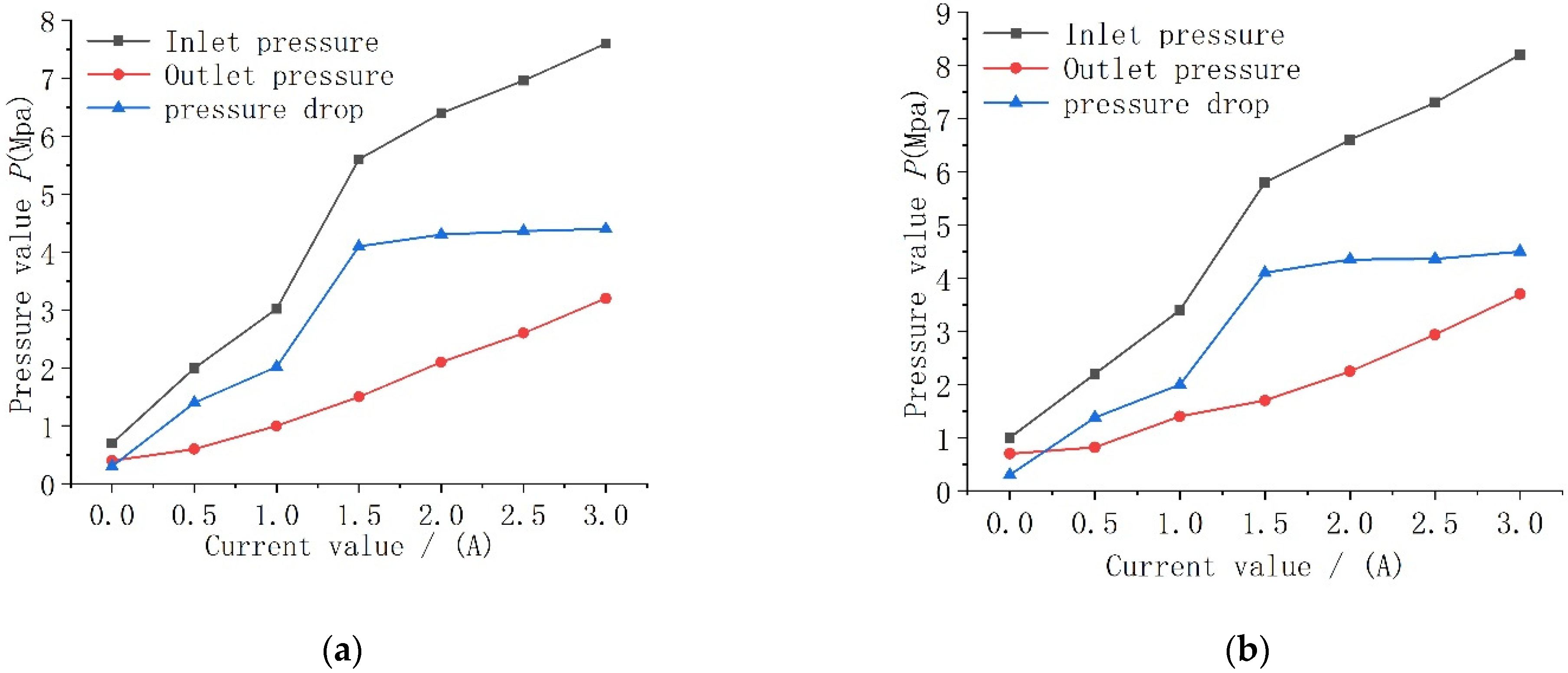
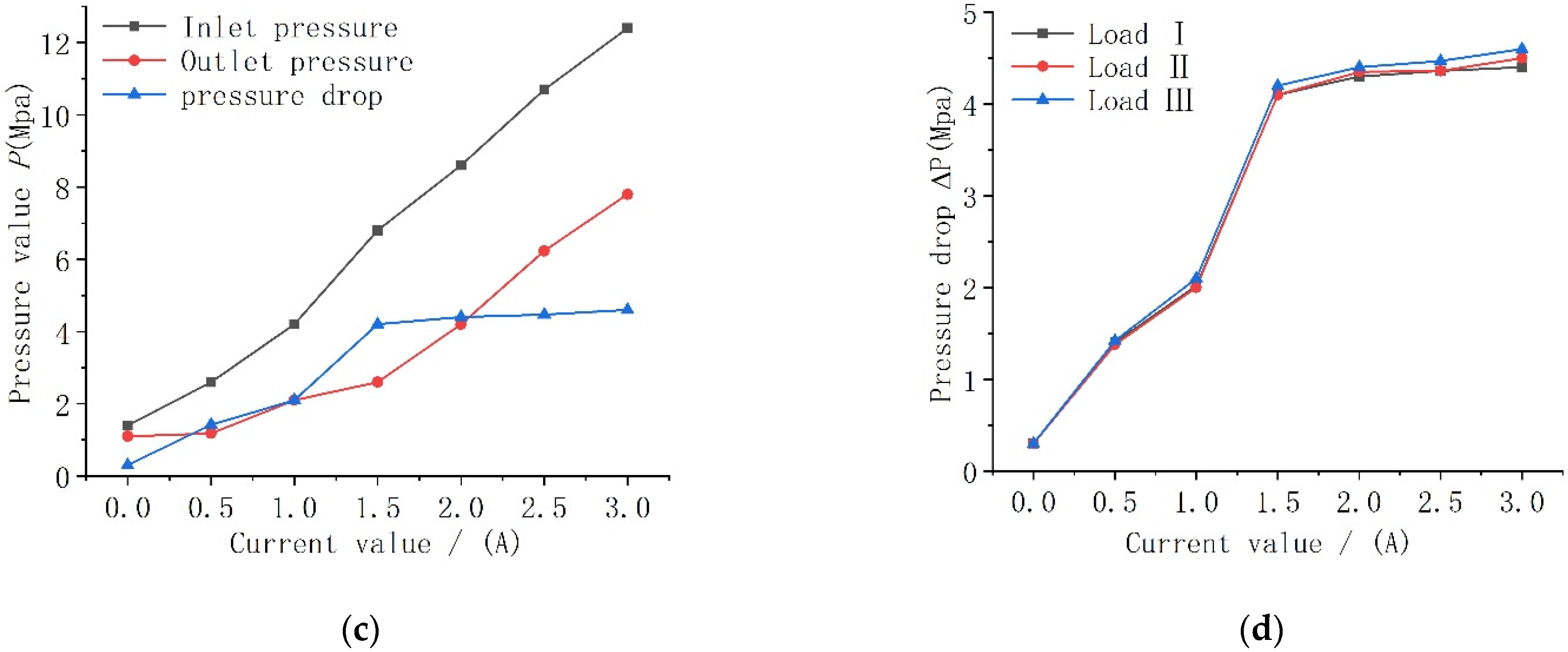
5.1. Influence of Different Loads on Pressure Drop Performance of Annular Multi-Channel MR Valve
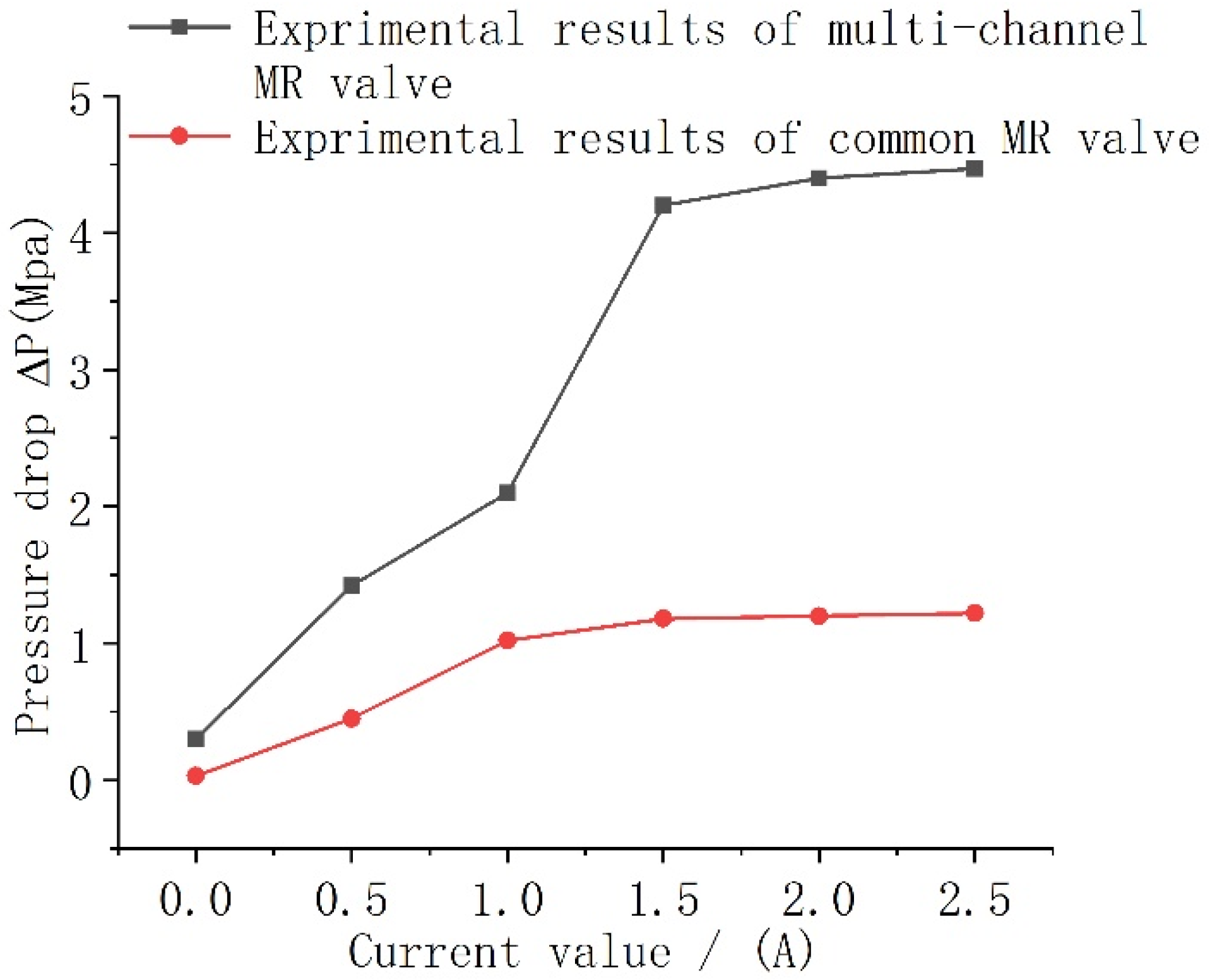
5.2. Comparison of Annular Multi-Channel MR Valve and Common MR Valve
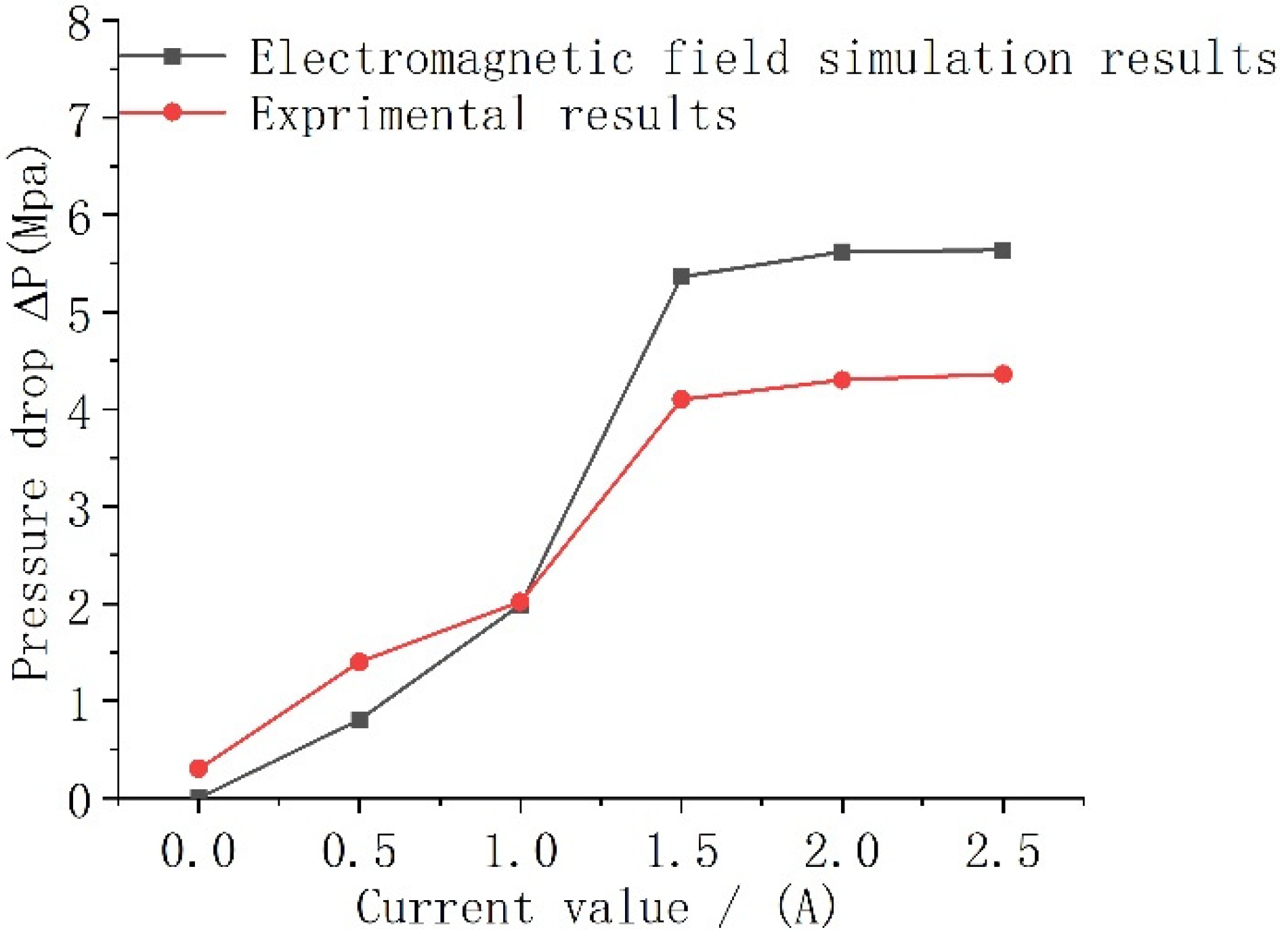
5.3. The Simulation Results Are Compared with the Experimental Results
6. Conclusions
- (1)
- Display of magnetic circuit design results: The number of turns required by a single excitation coil is greater than 321.
- (2)
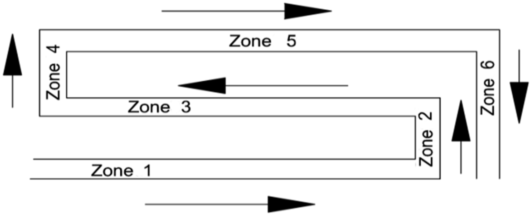
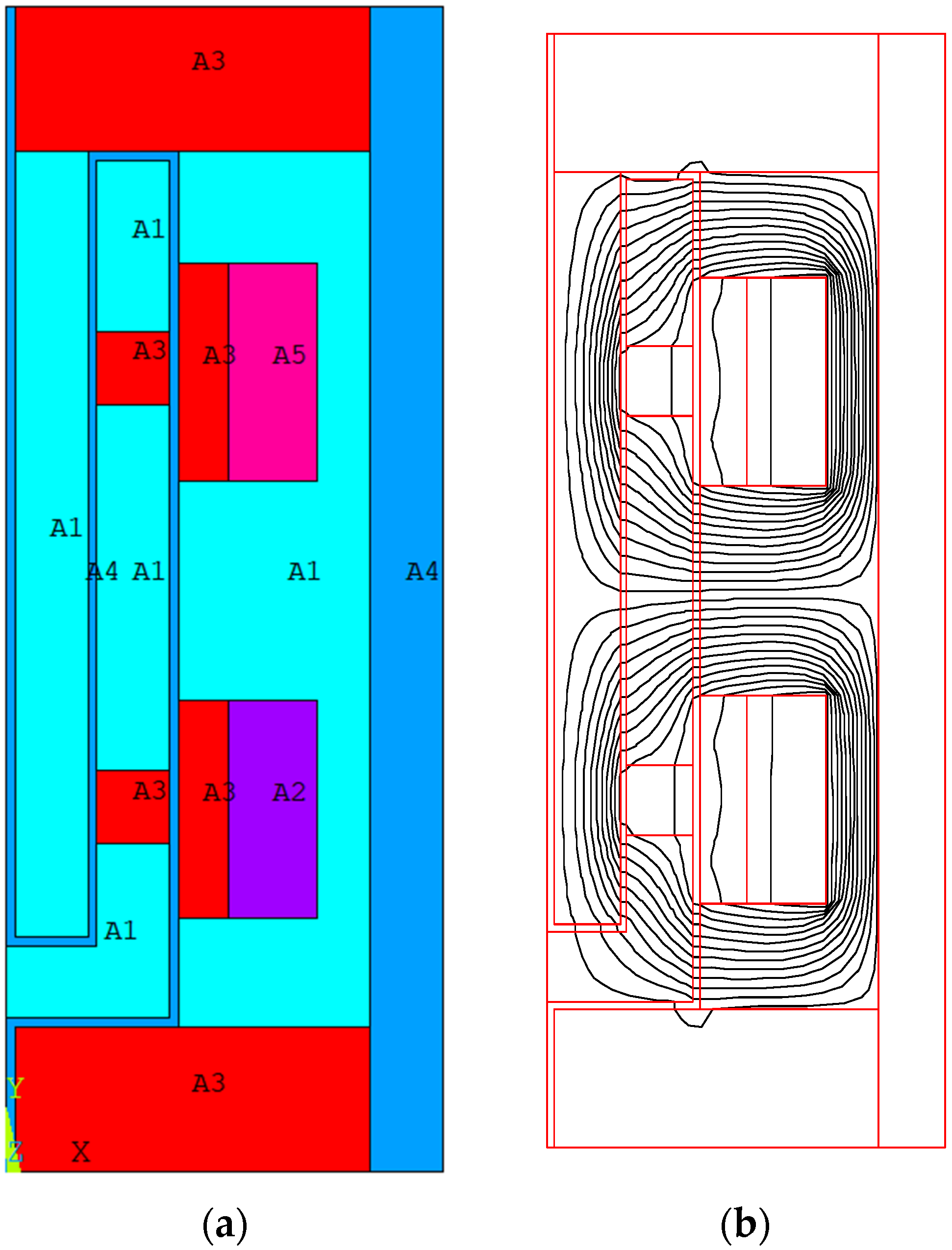
- Electromagnetic field finite element analysis results: The pressure drop performance of annular multi-channel MR valve increases with the increase of current and coil turns and decreases with the increase of spool thickness and damping clearance. Compared with the common MR valve, the pressure drop performance of the annular multi-channel MR valve is 5.6 times better than that of the common MR valve. This is because the effective flow length of the annular multi-channel MR valve is 3.2 times that of the ordinary magnetorheological valve, and the magnetic flux density that passes through the damping gap vertically is the same. Therefore, the longer the effective flow length, the better the pressure drop performance of the magnetorheological valve. Second, when MRF flows in a small gap, it is forced to change the flow direction at the shoulder of the shaft, which will consume part of the energy. Therefore, the performance of the annular multi-channel MR valve far exceeds the pressure drop performance of the ordinary MR valve.
- (3)
- Experimental results show that the pressure drop performance curves of the annular multi-channel MR valve coincide under different loads, so the load has little influence on the pressure drop performance of the annular multi-channel MR valve. Compared with the common type, the pressure drop performance of the annular multi-channel MR valve is improved 2–3.7 times, which is basically consistent with the simulation results.
Author Contributions
Funding
Institutional Review Board Statement
Informed Consent Statement
Conflicts of Interest
References
- Idris, M.H.; Imaduddin, F.; Mazlan, S.A.; Choi, S.B. A concentric design of a bypass magnetorheological fluid damper with a serpentine flux valve. Actuators 2020, 9, 16. [Google Scholar] [CrossRef] [Green Version]
- Chen, P.; Qian, L.J.; Bai, X.X.; Choi, S.B. Velocity-dependent characteristics of magnetorheological fluids in squeeze mode considering the hydrodynamic and the magnetic field interactions. J. Rheol. 2017, 61, 455–465. [Google Scholar] [CrossRef]
- Ruan, X.H.; Wang, Y.; Xuan, S.H.; Gong, X. Magnetic field dependent electric conductivity of the magnetorheological fluids: The influence of oscillatory shear. Smart Mater. Struct. 2017, 26, 35067. [Google Scholar] [CrossRef]
- Versaci, M.; Cutrupi, A.; Palumbo, A. A Magneto-Thermo-Static Study of a Magneto-Rheological Fluid Damper: A Finite Element Analysis. IEEE Trans. Magn. 2020, 57, 1–10. [Google Scholar] [CrossRef]
- Nguyen, Q.H.; Choi, S.B.; Lee, Y.S.; Han, M.S. Optimal design of high damping force engine mount featuring MR valve structure with both annular and radial flow paths. Smart Mater. Struct. 2013, 22, 5024. [Google Scholar] [CrossRef]
- Abd Fatah, A.Y.; Mazlan, S.A.; Koga, T.; Zamzuri, H. Increasing Effective Region in Magnetorheological Valve using Serpentine Flux Path Method. In Proceedings of the 2013 World Congress on Advances in Structural Engineering and Mechanics, Jeju, Korea, 8–12 September 2013; pp. 2916–2929. [Google Scholar]
- Hu, G.; Liao, M.; Li, W. Analysis of a compact annular-radial-orifice flow magnetorheological valve and evaluation of its performance. J. Intell. Mater. Syst. Struct. 2017, 28, 1321333. [Google Scholar] [CrossRef] [Green Version]
- Abd Fatah, A.Y.; Mazlan, S.A.; Koga, T.; Zamzuri, H.; Zeinali, M.; Imaduddin, F. A review of design and modeling of magnetorheological valve. Int. J. Mod. Phys. B 2015, 29, 1530004. [Google Scholar] [CrossRef] [Green Version]
- Hai, X.; Wang, D.H.; Liao, W.H. Design and modeling of a magnetorheological valve with both annular and radial flow. J. Intell. Mater. Syst. Struct. 2006, 17, 327–334. [Google Scholar] [CrossRef]
- Imaduddin, F.; Mazlan, S.A.; Rahman, M.A.A.; Zamzuri, H.; Ichwan, B. A high performance magnetorheological valve with a meandering flow path. Smart Mater. Struct. 2014, 23, 065017. [Google Scholar] [CrossRef]
- Imaduddin, F.; Mazlan, S.A.; Zamzuri, H.; Yazid II, M. Design and performance analysis of a compact magnetorheological valve with multiple annular and radial gaps. J. Intell. Mater. Syst. Struct. 2015, 26, 1038–1049. [Google Scholar] [CrossRef]
- Hu, G.; Zhou, F.; Yu, L. Optimal Design and Performance Analysis of Radial MR Valve with Single Excitation Coil. Actuators 2021, 10, 34. [Google Scholar] [CrossRef]
- Hu, G.; Zhang, J.; Zhong, F.; Yu, L. Performance evaluation of an improved radial magnetorheological valve and its application in the valve controlled cylinder system. Smart Mater. Struct. 2019, 28, 047003. [Google Scholar] [CrossRef]
- Sahin, H. Theoretical and Experimental Studies of Magnetorheological (MR) Fluids and MR Greases/Gels from Rheology to System Application. Ph.D. Thesis, University of Nevada, Reno, NV, USA, 2008. [Google Scholar]
- Sahin, H.; Gordaninejad, F.; Wang, X.; Liu, Y. Response time of magnetorheological fluids and magnetorheological valves under various flow conditions. J. Intell. Mater. Syst. Struct. 2012, 23, 949–957. [Google Scholar] [CrossRef]
- Hu, G.L.; Zhang, J.W.; Liao, M.K.; Ding, R.Q. The effect of radial resistance gap on the pressure drop of a compact annular-radial-orifice flow magnetorheological valve. J. Beijing Inst. Technol. 2018, 27, 535–546. [Google Scholar]


| Project | Parameter |
|---|---|
| density | 2.65 g/cm3 |
| Zero field viscosity (r = 10/s, 20 °C) | 0.8 Pa s |
| Shear stress (5000 Gs) | 50 kPa |
| temperature range | −40~130 °C |
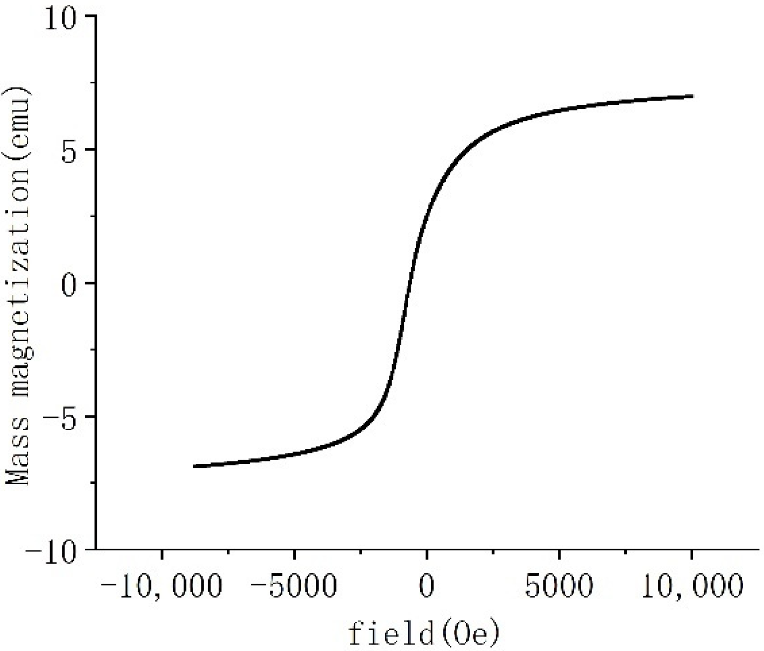
| Magnetization performance (Ms) | 365.29 KA/m |
| Numerical Value (mm) | Parameter | Numerical Value (mm) | |
|---|---|---|---|
| The damping clearance (r1) | 1 | Magnetic disk 11 width (h2) | 10 |
| The thickness of the valve core (r2) | 10 | Left magnetic block 14 width (h3) | 24 |
| Magnetic block thickness (r3) | 19 | Middle magnetic block 12 width (h4) | 48 |
| The thickness of the shell (r4) | 8 | Left coil holder 4 width (h5) | 15 |
| Height of the coil (w) | 12 | Middle coil stand 4 width (h6) | 30 |
| The width of the coil (t) | 30 | The shell width (h7) | 120 |
| The width of the valve core (h1) | 108 | The end cover width (h8) | 20 |
| Magnetic Resistance | Value (H/mm) | Magnetic Resistance | Value (H/mm) |
|---|---|---|---|
| ra1 | 20.65 | 21.52 | |
| 3.34 | 2.36 | ||
| 91.78 | 91.78 | ||
| 2.36 | 3.34 | ||
| 175.93 | 20.65 | ||
| 4.72 | 37.28 | ||
| 183.56 | 12.75 | ||
| 6.68 | 45.89 | ||
| 351.86 | 21.52 | ||
| 21.52 | 315.58 | ||
| 546.82 | 162.44 | ||
| 654.06 |
Publisher’s Note: MDPI stays neutral with regard to jurisdictional claims in published maps and institutional affiliations. |
© 2022 by the authors. Licensee MDPI, Basel, Switzerland. This article is an open access article distributed under the terms and conditions of the Creative Commons Attribution (CC BY) license (https://creativecommons.org/licenses/by/4.0/).
Share and Cite
Yang, X.; Chen, Y.; Liu, Y.; Zhang, R. Modeling and Experiments of an Annular Multi-Channel Magnetorheological Valve. Actuators 2022, 11, 19. https://doi.org/10.3390/act11010019
Yang X, Chen Y, Liu Y, Zhang R. Modeling and Experiments of an Annular Multi-Channel Magnetorheological Valve. Actuators. 2022; 11(1):19. https://doi.org/10.3390/act11010019
Chicago/Turabian StyleYang, Xiaolong, Yingjie Chen, Yuting Liu, and Ruibo Zhang. 2022. "Modeling and Experiments of an Annular Multi-Channel Magnetorheological Valve" Actuators 11, no. 1: 19. https://doi.org/10.3390/act11010019
APA StyleYang, X., Chen, Y., Liu, Y., & Zhang, R. (2022). Modeling and Experiments of an Annular Multi-Channel Magnetorheological Valve. Actuators, 11(1), 19. https://doi.org/10.3390/act11010019