Article

An Enhanced Sliding Mode Speed Control for Induction Motor Drives

by
Fahimeh Shiravani
1,*,
Patxi Alkorta
1,
Jose Antonio Cortajarena
1 and
Oscar Barambones
2,*
1
Engineering School of Gipuzkoa, University of the Basque Country, Otaola Hirib. 29, 20600 Eibar, Spain
2
Engineering School of Vitoria, University of the Basque Country, Nieves Cano 12, 01006 Vitoria, Spain
*
Authors to whom correspondence should be addressed.
Actuators 2022, 11(1), 18; https://doi.org/10.3390/act11010018
Submission received: 9 December 2021 / Revised: 28 December 2021 / Accepted: 3 January 2022 / Published: 10 January 2022
(This article belongs to the Special Issue New Control Schemes for Actuators)

Abstract

:
In this paper, an enhanced Integral Sliding Mode Control (ISMC) for mechanical speed of an Induction Motor (IM) is presented and experimentally validated. The design of the proposed controller has been done in the d-q synchronous reference frame and indirect Field Oriented Control (FOC). Global asymptotic speed tracking in the presence of model uncertainties and load torque variations has been guaranteed by using an enhanced ISMC surface. Moreover, this controller provides a faster speed convergence rate compared to the conventional ISMC and the Proportional Integral methods, and it eliminates the steady-state error. Furthermore, the chattering phenomenon is reduced by using a switching sigmoid function. The stability of the proposed controller under parameter uncertainties and load disturbances has been provided by using the Lyapunov stability theory. Finally, the performance of this control method is verified through numerical simulations and experimental tests, getting fast dynamics and good robustness for IM drives.

1. Introduction

Three-phase machines, such as motors and generators, are used extensively in industry and in civil engineering. Renewable energy sources, machine tools, servo drives, and robots are just a few examples. Because of its low cost, minimal maintenance, low moment of inertia, robust architecture, and operational reliability, IM has become widely employed in various applications as power electronics technology has advanced. In the last two decades, the FOC technique has been the most widely used method for regulating IM in high-performance applications, such as speed and position control of three-phase motors. The torque and flux control current commands for the IM are decoupled by using the FOC method. As a result, the machine is controlled as if it were an independent DC machine. However, uncertainties such as unexpected parameter variations, external load disturbances, and nonlinear dynamics continue to impact the IM’s control performance. The Proportional Integral (PI) regulator, due to its simplicity, clear functionality, and effectiveness, is one of the most popular control techniques which has been used in electrical machines [1]. Nonetheless, because the IM is a nonlinear framework, a well-designed nonlinear regulator can improve action in the presence of disturbances and uncertainty [2]. Many authors have taken use of different advanced control approaches to govern the power electronics and drives area in this regard. For instance, adaptive control method [3], Backstepping algorithm [4,5], predictive control method [6] and Sliding Mode Control (SMC) [7,8,9]. Among the nonlinear control method, the SMC technique has become a fascinating nonlinear control method with a particular dynamic performance for IM, such as strong robustness, quick response, and simple software and hardware implementation [10].
Almost ever since sliding mode ideas imply, the considerable noise which some of the sliding mode controllers expose is not pleasant for control engineers and sometimes has led to resentments and even rejection of the technique. The phenomenon is best known as chattering. Chattering is a high-frequency oscillation around the equilibrium point, which arises because of the discontinuous nature of the control action. Due to this, the well-designed control action stands unsuitable for many practical applications. This behavior creates a problem of wear and tear within the mechanical parts, vibrations within the machines, or flapping of wing vanes in aerospace and hitting effect. Hence, it is unwanted in light of implementation [11]. Regarding chattering suppression, various types of chattering prevention schemes have been suggested [12,13,14]. For instance, many authors have been designing regulators for IM based on combining SMC theory and other advanced control methods such as backstepping algorithm, adaptive method, and fuzzy technique [15,16,17]. It should be noted that using SMC by employing other sorts of nonlinear control strategies increments the controller complexity and computational endeavors, which is incompatible with the ease of SMC. Another solution could be applying higher order sliding mode control to IM. For instance, in [18], authors have taken advantage of the super-twisting sliding mode method to eliminate the chattering phenomenon. Furthermore, discrete-time sliding mode control has been applied to the machine in this regard [19,20].
Another way to reduce the chattering phenomenon is to apply some changes to the traditional sliding surface, which is basically based on error and its derivative signal [21]. In [21,22,23,24], an integral sliding surface has been applied to the IM to eliminate steady-state error, which has been named ISMC. A sensorless adaptive ISMC for IM has been discussed in [21]. In [22], a speed estimator based on the ISMC method for IM has been designed where stator current controllers consist of a PI and an ISMC controller, which means more complexity. Besides, this speed estimator is not universal and can only be implemented in conjunction with the above current controller. Furthermore, the authors in [23] designed an ISMC anti-windup in the speed control loop of the IM. Furthermore, an ISMC method has been proposed in [24] to start the sensorless IM in the rotating condition.
In this paper, the considered IM is under load torque and it is perturbed by model uncertainties. The common objective in nearly all industrial control design procedures is to provide a fast and accurate response by employing a smooth and effective electromagnetic torque. This goal will be achieved by designing an efficient control law. The idea is to regulate the mechanical rotor speed of IM by using ISMC method to achieve asymptotic speed tracking and disturbance rejection. In the controller design process, the FOC theory has been applied to get fast dynamic performance. Furthermore, to tackle the chattering problem and to eliminate the steady-state error, the proposed robust controller is designed based on the ISMC while using a continuous switching function a r c t a n ( ) . Besides, the proposed controller has a faster speed convergence rate compared to the conventional ISMC method, due to the surface design difference. Compared with the conventional ISMC, in this paper, the a r c t a n ( ) function of the error of the mechanical speed has been considered in the surface design. By employing this function, the control action becomes smoother and provides a faster dynamics. Additionally, the presented proposal offers good robustness under parametric uncertainties. Then, by using a Lyapunov-based approach, robust output tracking of rotor speed is achieved. Since most of the electric drives in the industry are controlled by PI regulators, this proposal also has been compared with the PI controller to demonstrate the ability of the proposed controller in fast convergence of the speed of the IM. Furthermore, worth noting that, in this work, the experiments have been done by use of a 7.5 kW commercial IM, which shows the applicability of the projected methodology for the real applications within the industry.
The paper has been organized as follows: the speed controller of IM is designed in Section 2. In Section 3, the experiment platform and the effectiveness of the proposed controller by employing several simulations and experimental tests are shown. Finally, in Section 4, the conclusion has been presented.

2. Robust Speed ISMC Design

2.1. Model of the Mechanical Loop of IM

The block diagram of the proposed control scheme is shown in Figure 1. In this figure by starting from the right side of this block set, by measuring the three stator phase currents, and by using the Clarke’s and Park’s transformations (ABC d q block), the i s d and i s q components in the rotational reference frame are obtained. The resulting transformed currents i s d and i s q will be responsible for magnetizing rotor flux and electromagnetic torque, respectively. The block Calc θ s calculates the rotor flux angle, θ s , by using the indirect FOC control technique. The speed error between the reference and real speed is fed to the I S M C ω m block (speed regulator). The output of the block will be i s q * , which is responsible for the electromagnetic torque reference generation. Torque and flux currents are also controlled by the mean of the two P I i s d and P I i s q current regulators, which are providing the correspondent v s d * and v s q * voltage references in the rotating reference frame. They are transformed to the stationary reference frame by using the inverse park transformation block (dq α β block), giving v α * and v β * voltage references. These two voltages are applied to the modulator Space Vector Pulse Width Modulation (SVPWM), which transforms stationary reference frame voltages to control signals (pulses) to drive the power three-phase inverter IGBTs.
ISMC speed controller is designed in the d-q synchronous reference frame by using the indirect FOC, where it is assumed that ψ r q = 0 and consequently ψ r = ψ r d . Thus, the equation of the inductions electromagnetic torque of the motor has the following expression,
T e = 3 p L m 4 L r ψ r i s q = K T i s q
where K T is the torque constant:
K T = 3 p L m 4 L r ψ i r
Taking the mechanical equation:
J ω ˙ m + B v ω m + T L = T e
it can be written as:
ω ˙ m + a ω ω m + f ω = b ω i s q
where the following parameters can be defined as: a ω = B v / J , b ω = K T / J , f ω = T L / J

2.2. Basic Principles of ISMC

There are two phases to the ISMC regulator’s design. The first step is to choose the adequate integral sliding surface to meet the control goals. The second step is to design the control law, which ensures that the system’s trajectories reach and remain on the sliding surfaces in a finite amount of time (reaching phase). In this approach, the ISMC project may be categorized into two sections: defining an appropriate sliding surface S ( x ) and developing a control law. To reach the sliding regime, the conventional ISMC requires an error as well as its integral signal [25].
S ( x ) = ( μ f + d / d t ) r 1 e d τ
where e = ( x * x ) is the error, x is the system state space, x * is system state space reference, r is the degree of the sliding mode, and μ f is the weighting factor. The sliding mode control was used to assess the generic system (6) in [23], and the design process was thoroughly described.
x ˙ = f ( x ) + g ( x ) U c y = h ( x )
where x R n is the state space vector, U c R m is the input control action, and y ( t ) R p is the system output. U c can be obtained by using equivalent control method [23]:
U C = U e q u + U n
where U e q u is the equivalent control action that ensures the system’s convergence. It is calculated off-line with the use of a model that precisely represents the plant. Furthermore, U n is a switching control action that assures the attractiveness of the surface in the system state space.
U n = β s g n ( S ( x ) )
The positive gain β in the above equation will be designed to ensure the Lyapunov stability criterion.

2.3. Conventional ISMC for IM (D1 Design)

To continue, the mechanical (4) is considered under parameter uncertainty terms of the a ω , f ω and b ω as ( Δ a ω , Δ f ω , Δ b ω ),
ω ˙ m = ( a ω + Δ ω ) ω m ( f ω + Δ f ω ) + ( b ω + Δ b ω ) i s q
now the speed tracking error is defined as:
e ω = ω m ω m *
which ω m * is the mechanical rotor speed reference, and by taking its derivative:
e ˙ ω = ω ˙ m ω ˙ m * = a ω e ω + u ω + d ω
where the control law is defined as:
u ω = a ω ω m * + b ω i s q f ω ω ˙ m *
and compiling the uncertainty terms in d ω term, the following expression is obtained:
d ω = Δ a ω ω m Δ f ω + Δ b ω i s q
Now the sliding variable s ω ( t ) is defined with an integral component as:
s ω = e ω + 0 t K ω e ω d t
The following assumptions are formulated in order to obtain speed tracking: (A1) The constant K ω should be chosen such that K ω > 0 for all time. The law u ω should be designed in a way that guarantees convergence to the sliding surface in a finite time. Therefore:
u ω = a ω e ω K ω e ω β ω s i g n ( s ω )
(A2) The gain β ω must be chosen so that | d ω | < β ω , for all times.
Finally, the torque current reference, i s q * , is obtained directly by substituting (15) in (12),
i s q * = 1 / b ( a ω e ω K ω e ω β ω s i g n ( s ω ) + a ω ω m * + f ω + ω ˙ m * )
Theorem 1.
According to (1), the torque current command (16) will control the T e . Consequently, based on (3), the rotor speed will be regulated so that speed tracking error (10) tends to zero asymptotically, as the time tends to infinity.
Proof. 
Taking the derivatives of sliding surface s ω gives,
s ˙ ω = e ˙ ω + d / d t 0 t K ω e ω d τ = a ω e ω + u ω + d ω + K ω e ω
Substituting the control law (15) into (17) yields:
s ˙ ω = d ω β ω s g n ( s ω )
now, by considering the Lyapunov function as v ω = 1 2 s ω 2 , then:
v ˙ ω = s ω s ˙ ω = s ω ( d ω β ω s g n ( s ω ) )
based on (A2),
v ˙ ω ε ω | s ω | ε ω | v ω | 1 / 2
where ε ω is a positive constant. Based on the Lyapunov’s direct method, since v ω is positive, v ˙ ω is negative definite and v ω tends to infinity as s ω tends to infinity. Therefore, s ω = 0 is globally asymptotically stable which means s ω tends to zero as time tends to infinity (sliding phase). Furthermore, all trajectories must reach to sliding surface in the finite time (reaching phase). When the sliding phase occurs, s ω = s ˙ ω = 0 , and as a result, the dynamic behavior of the tracking problem (11) is equivalently governed by the following equation:
s ˙ ω = 0 e ˙ ω = K ω e ω
The reduced order model (21) represents the system error. It can be said that based on (A1) the speed error tends to zero exponentially. Besides, in (21), K ω is the rate of error convergence to zero. However, based on (16) it may be deduced that a high value of K ω may produce a high control signal that could saturate the actuator. As it can be seen in the control law (19), the f ω term needs to be calculated and it is dependent on the load torque. Therefore, T L is estimated by using mechanical Equation (3).
T ^ L = T e J ω ˙ m B v ω m

2.4. Enhanced ISMC for IM (D2 Design)

This subsection designs the ISMC for IM mechanical rotor speed enhancing the surface, by integrating the a r c t a n ( ) of the mechanical speed error. In this regard by considering the generic sliding surface as:
S ( x ) = ( μ f + d / d t ) r 1 a r c t a n ( e ) d τ
for rotor speed of the IM could be obtained:
s ω = e ω + 0 τ K ω a r c t a n ( e ω ) d τ
Taking and following the same steps as the previous section, the mechanical rotor speed control law is designed.
Remark 1.
The control law (15) is a discontinuous function of the sliding surface which may cause to undesirable chattering problem as it contains a hard switch. Therefore, to alleviate ISMC chattering phenomena and to have a smooth transition, s i g n ( ) function is replaced by a r c t a n ( ) function which is a continous approximation of this function [26]. Consequently, the control law will be rewritten as:
u ω = a ω e ω K ω a r c t a n ( e ω ) β ω a r c t a n ( s ω )
and as a result, the torque current reference, i s q * , is obtained as,
i s q * = 1 / b ( a ω e ω K ω a r c t a n ( e ω ) β ω a r c t a n ( s ω ) + a ω ω m * + f ω + ω ˙ m * )
where a r c t a n ( ) function is the inverse function of t a n ( ) function.
It should be noted that the stability analysis is as same as in Section 2.3.

3. Simulation and Experimental Design

In this section, the experimental platform and the performance of the proposed speed regulation has been verified by means of MatLab/Simulink simulation and real tests using a commercial induction motor.
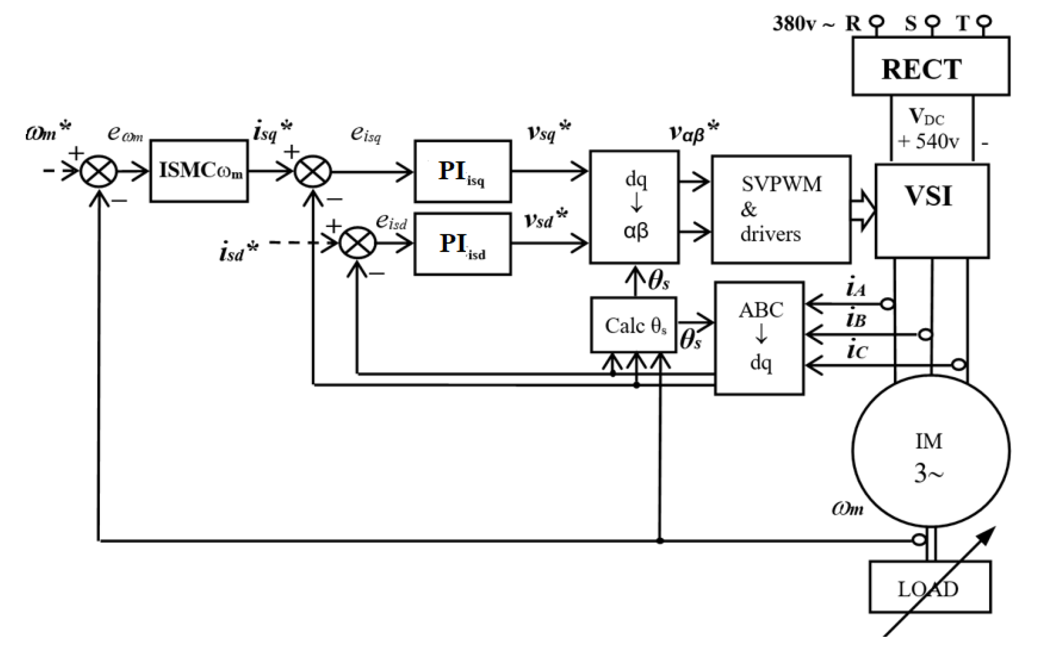
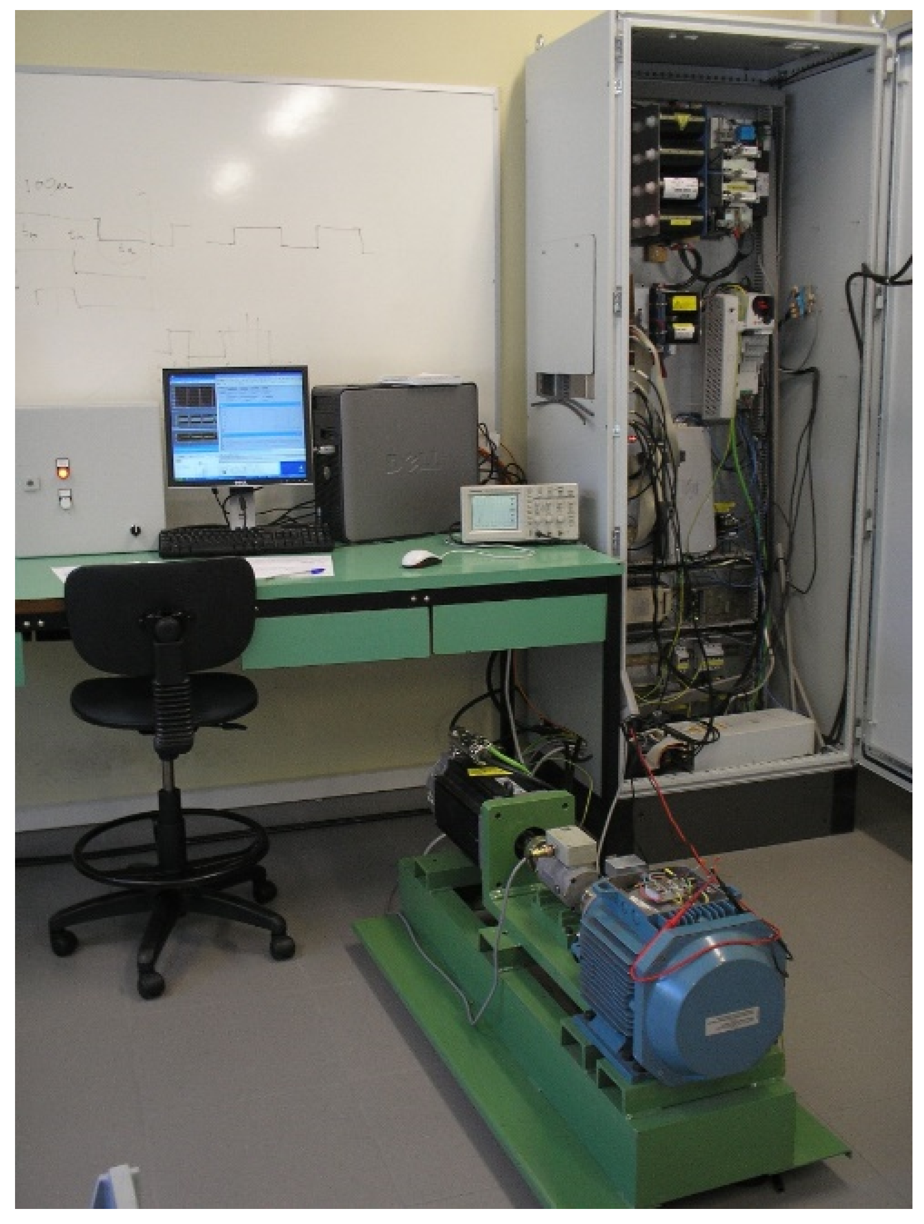
The experimental validation of proposed ISMC regulators has been carried out by means of the platform shown in Figure 2. This platform is based on a commercial squirrel-cage IM of 7.5 kW (M2AA 132M4, ABB) which is connected mechanically to a synchronous AC servo motor of 10.6 kW (190U2, Unimotor) in its shaft, to implement the load torque (controlled by torque). Table 1, shows the parameters of the IM installed in the experiment platform. Both machines are connected to a DC bus of 540 V by using their respective three-phase Voltage Source Inverters (VSI) with a switching frequency of 10 kHz (SVPWM modulator frequency). This way, the control and monitoring tasks are done from a Personal Computer, which contains the MatLab/Simulink software and dSControl application to control the DS1103 controller board real-time interface of dSpace. The mechanical speed of the machine is calculated by using a FPGA module and the measurements of an incremental encoder of 4096 impulses per revolution.
Three different design cases such as D1, D2 and PI have been applied to the same induction motor to validate the proposed enhanced regulator (D2 design). To run the experiments, the IM is using the values of the nominal parameters for the IM, which have been listed in Table 1, and the IM has been tested at three different speeds. Furthermore, parameters values of the ISMC speed regulator are: K ω = 1600 and β ω = 80 . On the other hand, the uncertainty test takes a moment of inertia which is 60 % lower than the nominal value (J = 0.0201 kg·m 2 ), while the rest of the machine parameters will be nominal values, then these parameters are K ω = 1700 and β ω = 20 . Regarding the adjustment of the two PI current regulators, both have been tuned by using a bandwidth of 3000 rad/s and a phase margin of 90 ( K p i s d , q = 11.81 , K i i s d , q = 2187 ) [27]. The mechanical speed PI regulator which is employed to compare with the enhanced ISMC speed regulator (D2 design), have been tuned taking a bandwidth of 300 rad/s and a margin phase of 82 ( K p ω m = 5.64 , K i ω m = 238 ). This way as faster as possible dynamics have been obtained experimentally by using PI regulators.
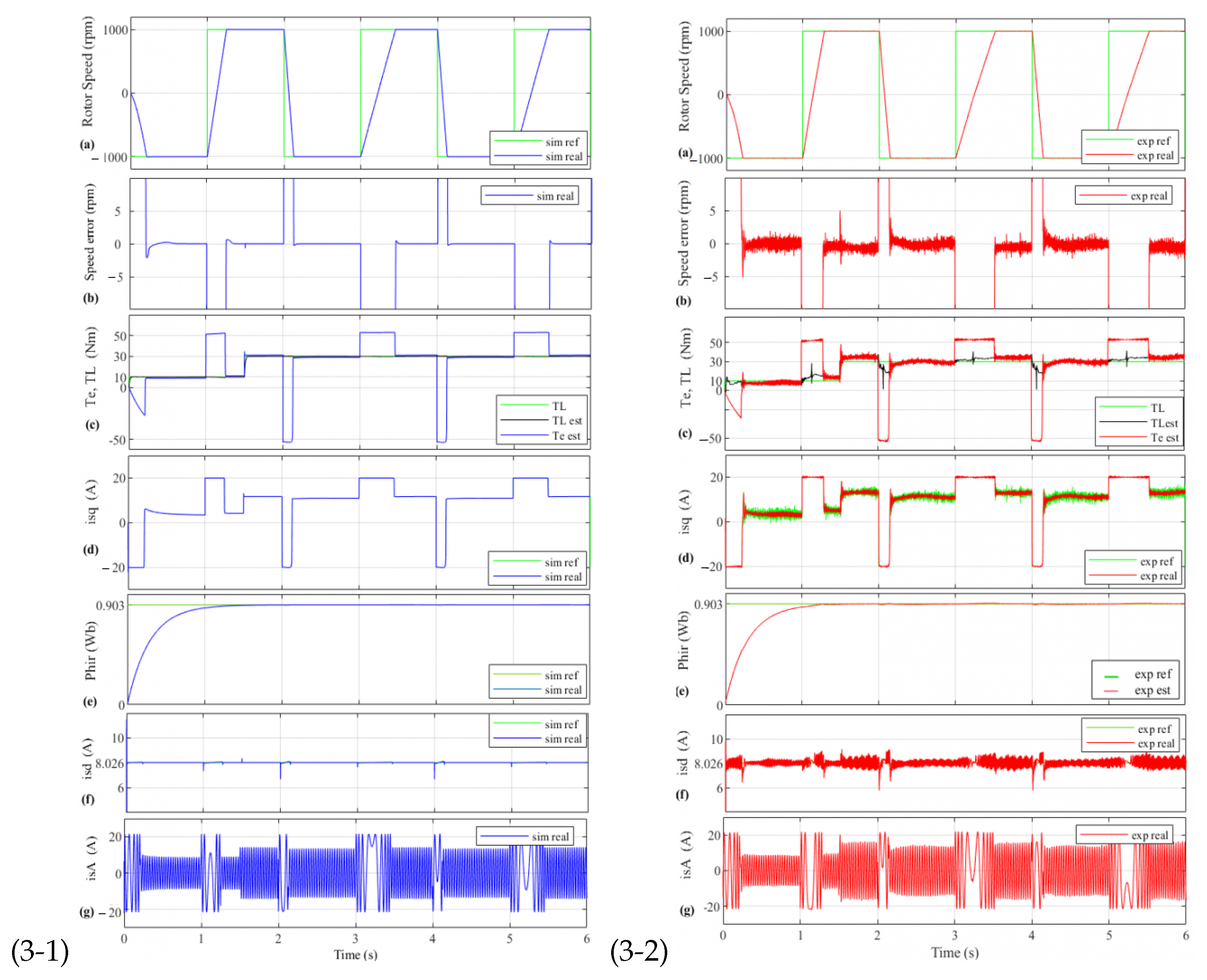
Figure 3(3-1) shows the performance of the machine by using a simulation test when the motor is working with a square speed reference of 1000 rpm with a period of 2 s, and the load torque is applied to the system in two steps: 10 Nm at the starting point and 30 nm at t = 1.5 s. In the first graph, (a), the reference and real rotor speed can be observed, and the second graph (b), shows the rotor speed error. As it can be seen, in the presence of a sudden change in the load torque the mechanical rotor speed tracks the desired speed properly with low error in steady-state (less than 1 rpm). The third graph, (c), shows the electromagnetic torque and load torque, where it can be appreciated that electromagnetic torque is smooth and consequently does not present any chattering. In (d) graph it can be seen that the stator torque current tracks the reference correctly. Moreover, this current is proportional to the electromagnetic torque which is also smooth and limited to its rated value (20 A). Graph (e) shows how the rotor flux tracks its reference adequately. Furthermore, the good response of the rotor flux current can be presented as graph (f). Finally, as the torque current is limited, the stator currents are also limited to a similar value that has been shown in the (g), keeping protected the stator windings against over-currents.
Figure 3(3-2) shows the performance of the machine by using the corresponding experimental test to the simulation test shown in Figure 3(3-1). In the Figure 3(3-2), the graphs (a) and (b) show that the speed tracking and the accuracy are very similar to the simulation case, getting fast dynamics and speed error in steady-state is less than 2 rpm. Regarding the electromagnetic torque (c), it can be compared with its simulation case, concluding that both are very similar, smooth, and efficient. Moreover, the estimated load torque is very similar to the load torque, which that demonstrates the estimator works properly. Graph (d) shows the reference and the real stator torque currents, which can be observed that the current tracking is very satisfactory and very similar to the simulation case (the form is proportional to the electromagnetic torque and limited to 20 A). In Figure 3(3-2), e and f graphs show how the rotor flux and rotor flux current adequately track their references. It can be observed that the two stator currents, i s d and i s q are decoupled. Finally, due to the limited torque current, the stator currents are also limited to similar values (g). By comparing simulation and experimental case in Figure 3, it can be seen that the simulation and the platform experiment have the same behavior, which is proof of the experimental validation of the presented ISMC speed controller (D2 design) and good system modeling.
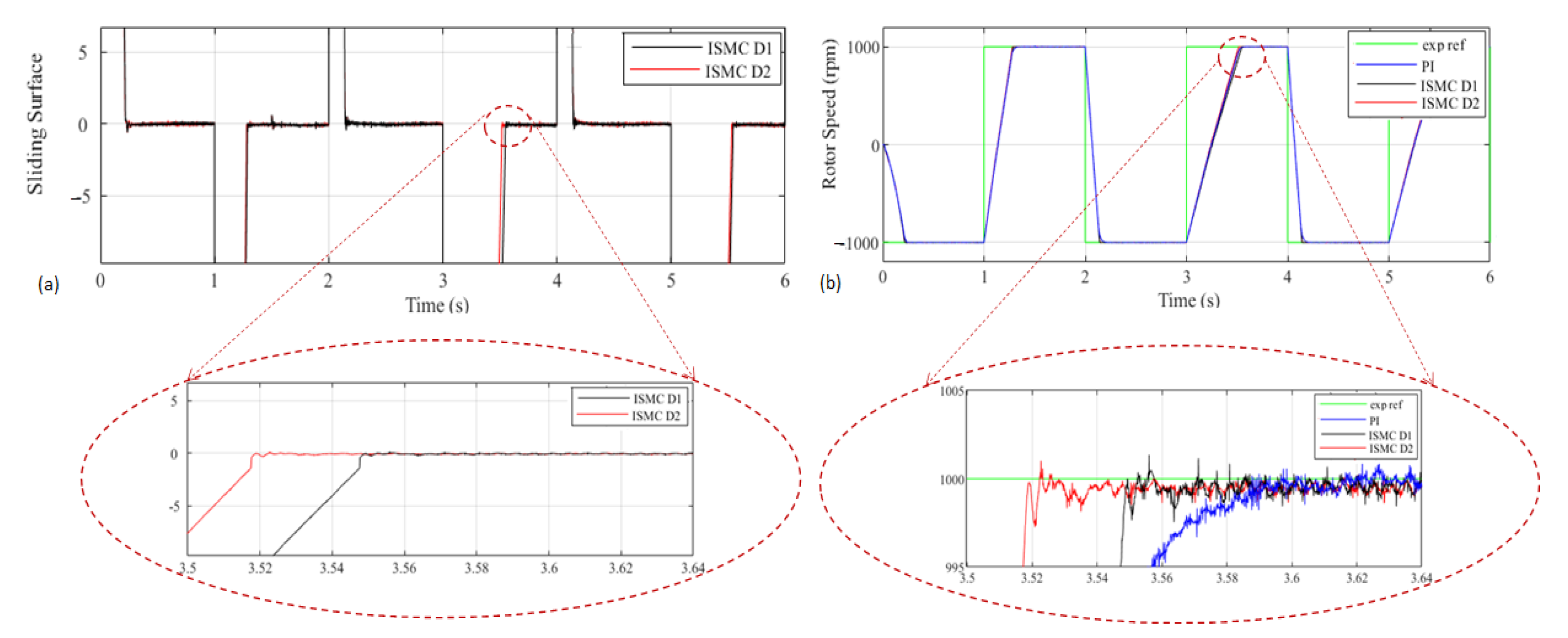
Figure 4 shows the experimental tests for performance comparison between the proposed ISMC speed controller (D2 design) and the conventional ISMC (D1 design) method by using the same speed and load conditions in the test of Figure 3. This illustration provides the sliding surface convergence and tracking speed performance for both controllers. It is evident in the zoom mode graphs that using the a r c t a n ( ) function of the speed error, instead of the s i g n ( ) function, in the surface design, provides faster error convergence to zero. Moreover, the PI speed regulator performance is also added to show that despite its performance being good its response is slower than the other two ISMC (D1 and D2 designs).
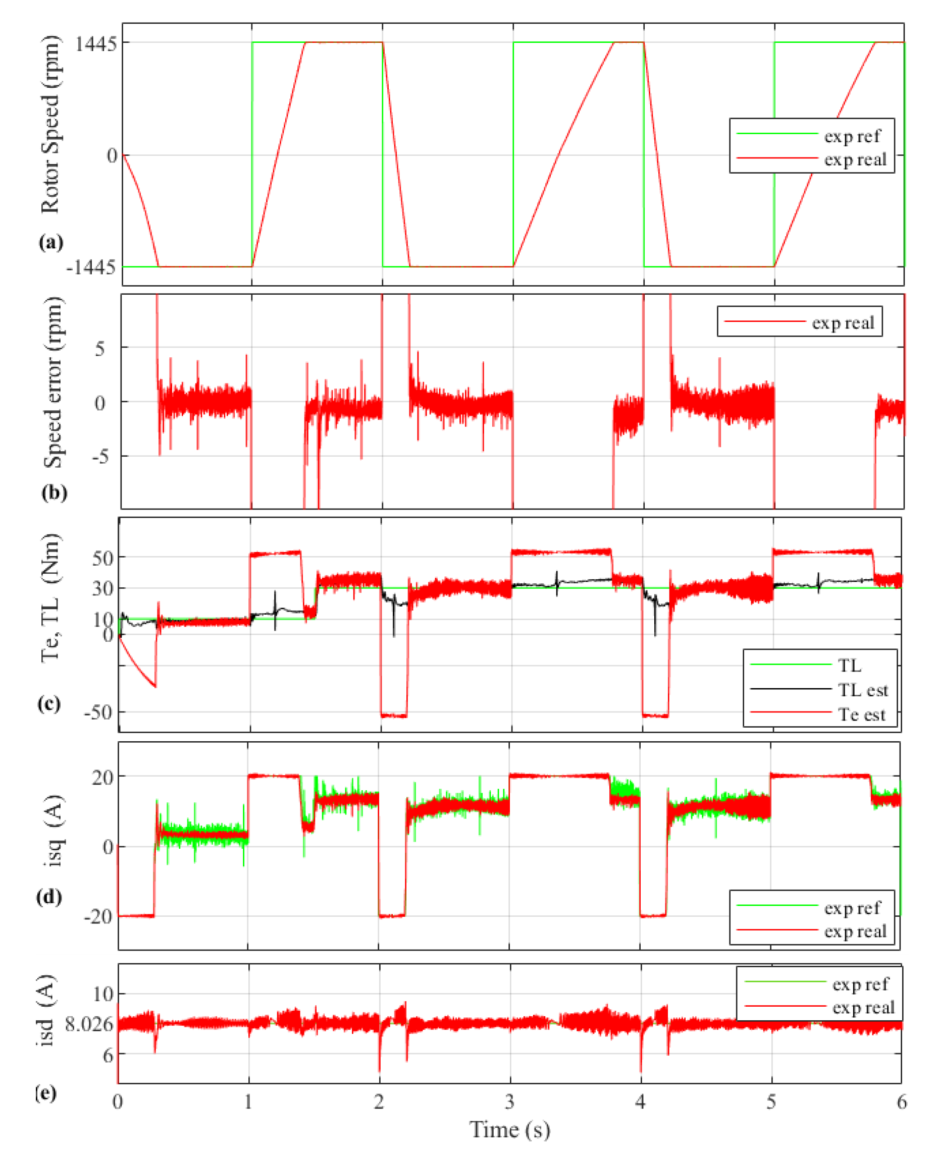
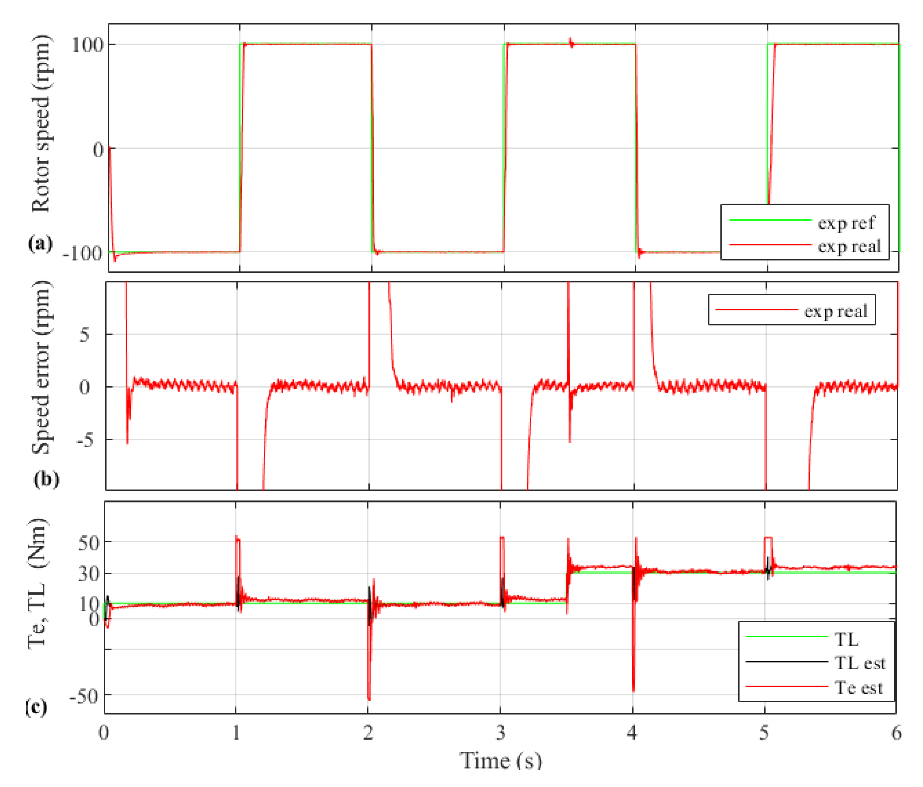
The performance of the motor when it is working at rated speed is shown in Figure 5 by employing a square speed reference of 1445 rpm and two load torque steps, starting at 0 s (10 nm) and t = 1.5 s (plus 20 nm). Graph Figure 5a shows how the actual speed tracks its reference accordingly, and graph Figure 5b shows that the speed error is limited to 3–4 rpm ( 0.27 % ), which means getting high accuracy in the presence of load disturbance. It can be observed in graph Figure 5c that the electromagnetic torque is smooth and effective, and also the load torque is estimated suitably. Figure 5d shows good tracking of the torque current. In Figure 5e, the precise rotor flux current tracking can be seen.
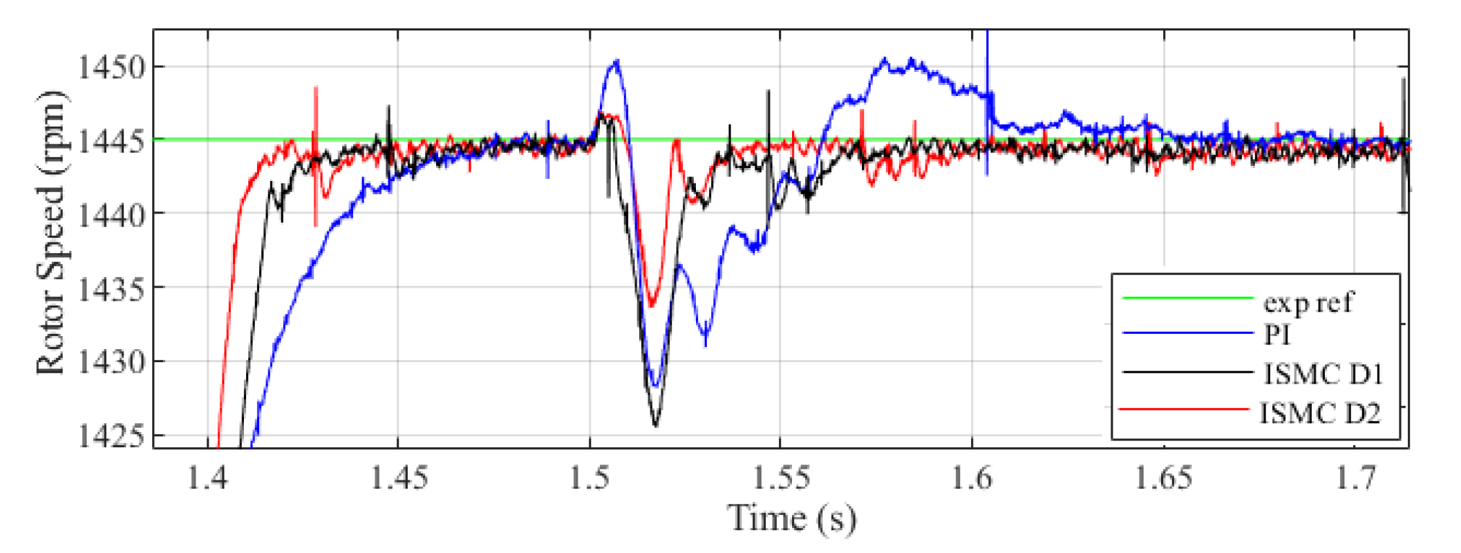
Figure 6 shows the experimental tests for performance comparison between the two ISMC and the PI speed regulators by using the same speed and load conditions as in the experiment of Figure 5. Worth noting that, in the tuning process of the PI controller, experimentally maximum bandwidth has been assigned to the regulator to have the fastest possible response in the rotor speed convergence. As it can be seen, the ISMC is converging to a reference signal faster than the PI controller even when the motor is working at a high speed, such as in the same way as is shown in the previous graph of Figure 5. Furthermore, at t = 1.5 s (when the second step of load torque is applied to the motor), the effect of the load torque is being rejected more efficiently employing the proposed ISMC (D2 design) compared with the conventional ISMC (D1 design) and the PI regulators: recovering period is faster, and the response presents less oscillation.
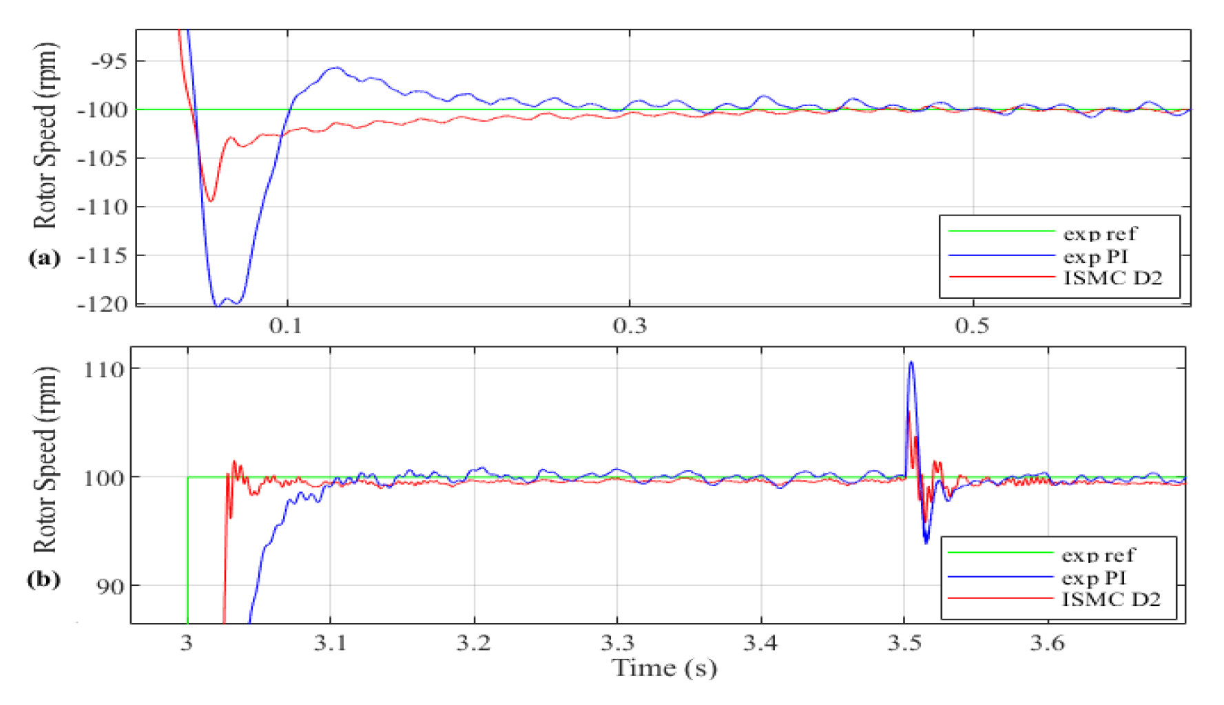
In Figure 7, the performance of the motor when it is working at low speed (100 rpm) with load disturbance ( T L = 10 Nm at t = 0 s and T L = 30 Nm at t = 3.5 s) can be seen. It can be observed that the speed tracking Figure 7a is very satisfactory. Furthermore, the accuracy in Figure 7b is excellent, getting an error of less than 2 rpm (0.16%). The electromagnetic torque necessary to get these good results is smooth, and consequently, it does not present the chattering phenomenon (Figure 7c).
Figure 8 shows the experimental tests for performance comparison between the enhanced ISMC (D2 design) and the PI speed regulators while using the same speed and load conditions as in Figure 8 test. The proposed ISMC is converging to a reference signal faster than the PI controller. Furthermore, at t = 3.5 s (after applying the second step of load torque) to the motor, the behavior of the enhanced ISMC is more robust due to the fast and more effective rejection of load torque.
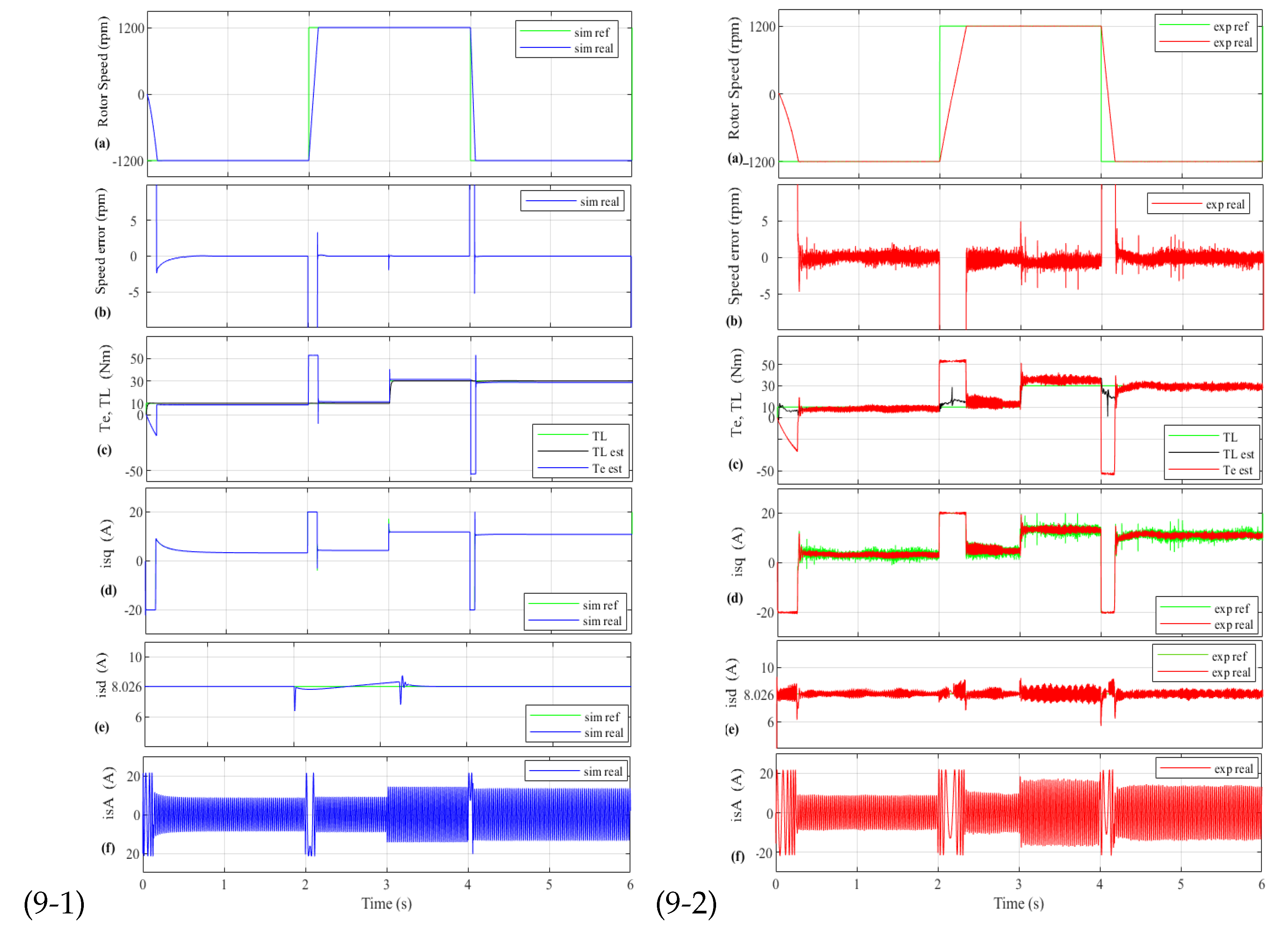
Figure 9(9-1) shows the simulation performance of the machine by using enhanced ISMC (D2 design), which takes a considerably minor J parameter ( 60 % lower), as mentioned before. The IM has been tested by employing 1200 rpm reference speed. In Figure 9(9-2), the result of experimental robustness performance corresponding to the provided simulation is demonstrated. Graph (a) shows the motor speed response. However, the speed tracking is good. Furthermore, the speed error (graph (b)) can be considered very satisfactory, which is around 2 rpm (0.16%). Finally, electromagnetic torque, stator torque current, rotor flux current, and three-phase of stator currents have been shown in graphs (c), (d), (e) and (f), respectively, and they can be considered very proper. Therefore, the robustness of the speed controller has been tested by changing an important parameter of the motor specification in the speed controller (J).

4. Conclusions

In this paper, ISMC is applied to the IM vector control system to regulate the mechanical rotor speed and reject the load disturbances and parametric variations. The proposed controller incorporates an integral part in the sliding surface to eliminate static machine errors and enhance regulator accuracy. Indeed, the stability analysis of the controller has been done based on the Lyapunov function approach. The MatLab/Simulink’s simulation and real tests utilizing a commercial IM have confirmed its experimental validation. In addition, the controller has good performance in practice because the speed tracking objective is achieved. The obtained accuracy for the speed regulator system can be considered excellent, getting a small speed error in stationary, which is between 0.16 % and 0.27 % for low, medium, and high speeds. Furthermore, it has been demonstrated that the presented enhanced ISMC speed regulator is more robust, efficient, and faster than the conventional ISMC and PI speed regulators. Finally, the regulators’ capability of rectifying system chattering effectively under important system mechanical uncertainties ( 60 % ) and load torque disturbance demonstrates good robustness of the controlled system.

Author Contributions

Conceptualization, F.S., P.A., J.A.C. and O.B.; methodology, F.S. and P.A.; software, F.S., P.A. and J.A.C.; validation, F.S., P.A. and J.A.C.; formal analysis, O.B.; investigation, F.S. and P.A.; resources, O.B.; data curation, P.A.; writing—original draft preparation, F.S.; writing—review and editing, F.S., P.A., J.A.C. and O.B.; visualization, J.A.C. and O.B.; supervision, P.A. All authors have read and agreed to the published version of the manuscript.

Funding

The University of the Basque Country (UPV/EHU) [grant number PIF 18/127] has funded the research in this paper.

Acknowledgments

The authors wish to express their gratitude to the Basque Government, through the project EKOHEGAZ (ELKARTEK KK-2021/00092), and to the UPV/EHU, through the project GIU20/063, for supporting this work.

Conflicts of Interest

The authors declare no conflict of interest.

Nomenclature

Symbols of Induction Motor
B v Viscous friction coefficient
JMoment of inertia
L m Magnetizing inductance
L s Stator inductance
L r Rotor inductance
R r Rotor resistance
R s Stator resistance
pNumber of poles
σ Coefficient of magnetic dispersion
T e Electromagnetic torque
T L Load or disturbance torque
ω m Mechanical rotor speed
ω s Synchronous speed
ψ r Rotor flux
IStator rated current

References

  1. Nguyen, P.; Quang, J.D. Vector Control of Three-Phase AC Machines; Springer: Heidelberg, Germany, 2008. [Google Scholar]
  2. Talla, J.; Leu, V.Q.; Šmídl, V.; Peroutka, Z. Adaptive Speed Control of Induction Motor Drive With Inaccurate Model. IEEE Trans. Ind. Electron. 2018, 65, 8532–8542. [Google Scholar] [CrossRef]
  3. Li, L.; Wang, M.; Yang, R.; Fu, Y.; Zhu, D. Adaptive Damping Variable Sliding Mode Control for an Electrohydrostatic Actuator. Actuators Multidiscip. Digit. Publ. Inst. 2021, 10, 83. [Google Scholar] [CrossRef]
  4. El Kharki, A.; Boulghasoul, Z.; Et-Taaj, L.K.; Oussi, Z.; Elbacha, A. Adaptive Speed Control of Induction Motor Drive With Inaccurate Model. In Proceedings of the 2019 4th World Conference on Complex Systems (WCCS), Ouarzazate, Morocco, 22–25 April 2019; pp. 1–8. [Google Scholar]
  5. Happyanto, D.C.; Fauzi, R.; Hair, J. Backstepping development as controller in fast response three phase induction motor based on indirect field oriented control. In Proceedings of the 2016 International Electronics Symposium (IES), Denpasar, Indonesia, 29–30 September 2016; Volume 65, pp. 25–30. [Google Scholar]
  6. Ortega, C.; Arias, A.; Espina, J. Predictive Direct Torque Control of Matrix Converter Fed Permanent Magnet Synchronous Machines. Asian J. Control 2014, 16, 70–79. [Google Scholar] [CrossRef]
  7. Wang, M.; Wang, Y.; Yang, R.; Fu, Y.; Zhu, D. A Sliding Mode Control Strategy for an ElectroHydrostatic Actuator with Damping Variable Sliding Surface. Actuators Multidiscip. Digit. Publ. Inst. 2021, 10, 3. [Google Scholar] [CrossRef]
  8. Cheng, X.; Liu, H.; Lu, W. Chattering-suppressed sliding mode control for flexible-joint robot manipulators. Actuators Multidiscip. Digit. Publ. Inst. 2021, 10, 288. [Google Scholar] [CrossRef]
  9. Lu, Y.; Tan, C.; Ge, W.; Li, B.; Lu, J. Improved Sliding Mode-Active Disturbance Rejection Control of Electromagnetic Linear Actuator for Direct-Drive System. Actuators Multidiscip. Digit. Publ. Inst. 2021, 10, 138. [Google Scholar] [CrossRef]
  10. Du, C.; Yang, C.; Li, F.; Gui, W. A Novel Asynchronous Control for Artificial Delayed Markovian Jump Systems via Output Feedback Sliding Mode Approach. IEEE Trans. Syst. Man Cybern. Syst. 2019, 49, 364–374. [Google Scholar] [CrossRef]
  11. Brandtstädter, H.; Tokio, M.; Buss, V.I.U. Sliding Mode Control of Electromechanical Systems. Ph.D. Thesis, Technische Universität München, Munich, Germany.
  12. Muñoz-Vázquez, A.J.; Parra-Vega, V.; Sánchez-Orta, A. Continuous fractional sliding mode-like control for exact rejection of non-differentiable Hölder disturbances. J. Math. Control Inf. 2015, 34, dnv064. [Google Scholar] [CrossRef]
  13. Ahifar, A.; Ranjbar, N.A.; Rahmani, Z. Finite-time terminal synergetic control of a class of nonlinear systems with unmatched uncertainties. J. Math. Control Inf. 2020, 37, 765–776. [Google Scholar] [CrossRef]
  14. Kikuuwe, R.; Prieto, P.J.; López-Rentería, J.A. Chattering of proxy-based sliding mode control in the presence of parasitic dynamics. J. Math. Control Inf. 2021, 38, 177–191. [Google Scholar] [CrossRef]
  15. Morawiec, M.; Lewicki, A. Speed Observer Structure of Induction Machine Based on Sliding Super-Twisting and Backstepping Techniques. IEEE Trans. Ind. Inform. 2021, 17, 1122–1131. [Google Scholar] [CrossRef]
  16. Chen, S.; Chiang, H.; Liu, T.; Chang, C. Precision Motion Control of Permanent Magnet Linear Synchronous Motors Using Adaptive Fuzzy Fractional-Order Sliding-Mode Control. IEEE/ASME Trans. Mechatron. 2019, 24, 741–752. [Google Scholar] [CrossRef]
  17. Morawiec, M.; Lewicki, A.; Wilczyński, F. Speed observer of induction machine based on backstepping and sliding mode for low-speed operation. Asian J. Control 2021, 23, 636–647. [Google Scholar] [CrossRef]
  18. Ilten, E.; Demirtas, M. Fractional order super-twisting sliding mode observer for sensorless control of induction motor, Compel. Int. J. Comput. Math. Electr. Electron. Eng. 2019, 38, 878–892. [Google Scholar] [CrossRef]
  19. Veselic, B.; Perunicic-Drazenovic, B.; Milosavljevic, C. High-Performance Position Control of Induction Motor Using Discrete-Time Sliding-Mode Control. IEEE Trans. Ind. Electron. 2008, 55, 3809–3817. [Google Scholar] [CrossRef]
  20. Comanescu, M. Minimum Time Speed Control of the Induction Motor Drive Using Discrete Time Sliding Mode. In Proceedings of the 2020 International Symposium on Power Electronics, Electrical Drives, Automation and Motion (SPEEDAM), Sorrento, Italy, 20–22 June 2020; pp. 213–218. [Google Scholar]
  21. Barambones, O.; Garrido, A.J.; Maseda, F.J. Integral sliding-mode controller for induction motor based on field-oriented control theory. IET Digit. Library 2007, 1, 786–794. [Google Scholar] [CrossRef]
  22. Comanescu, M. An Induction-Motor Speed Estimator Based on Integral Sliding-Mode Current Control. IEEE Trans. Ind. Electron. 2009, 56, 3414–3423. [Google Scholar] [CrossRef]
  23. Oliveira, C.; Aguiar, M.; Monteiro, J.; Pereira, W.; Paula, G.; Almeida, T. Vector Control of Induction Motor Using an Integral Sliding Mode Controller with Anti-windup. J. Control Autom. Electr. Syst. 2016, 27, 169–178. [Google Scholar] [CrossRef]
  24. Gou, L.; Wang, C.; Zhou, M.; You, X. Integral Sliding Mode Control for Starting Speed Sensorless Controlled Induction Motor in the Rotating Condition. J. IEEE Trans. Power Electron. 2016, 35, 4105–4116. [Google Scholar] [CrossRef]
  25. Slotine, J.J.E.; Li, W. Applied Nonlinear Control; Prentice Hall: Englewood Cliffs, NJ, USA, 1991. [Google Scholar]
  26. Khalil, H.K.; Quang, J.D. Nonlinear Control; Pearson Higher: London, UK, 2014. [Google Scholar]
  27. Mohan, N. Advanced Electric Drives: Analysis, Control, and Modeling Using MATLAB/Simulink; John Wiley & Sons: Hoboken, NJ, USA, 2014. [Google Scholar]
Figure 1. Block diagram of IM.
Actuators 11 00018 g001
Figure 2. Experiment platform for IM with load torque.
Actuators 11 00018 g002
Figure 3. IM performance by using 1000 rpm reference speed and two load torque step changes: (3-1) simulation and (3-2) experimental (D2 design): (a) Rotor speed; (b) Speed error; (c) T e , T L ; (d) Torque current; (e) Rotor flux; (f) Rotor flux current and (g) Stator current.
Actuators 11 00018 g003
Figure 4. Experimental tests for performance comparison between the proposed ISMC (D2 design) regulator and the conventional ISMC by using 1000 rpm reference speed (D1 design) and also with PI regulator.
Actuators 11 00018 g004
Figure 5. Experimental results by using 1445 rpm reference speed and two load torque step changes (D2 design): (a) Rotor speed; (b) Speed error; (c) T e , T L ; (d) Torque current and (e) Rotor flux current.
Actuators 11 00018 g005
Figure 6. Experimental tests for performance comparison between the D1, D2 and the PI regulators by using 1445 rpm reference speed.
Actuators 11 00018 g006
Figure 7. Experimental results by using 100 rpm reference speed and two load torque steps changes (D2 design): (a) Rotor speed; (b) Speed error and (c) T e , T L .
Actuators 11 00018 g007
Figure 8. Experimental tests for performance comparison between the proposed ISMC (D2 design) and the PI regulators by using 100 rpm reference speed.
Actuators 11 00018 g008
Figure 9. IM performance with 60 % of uncertainties in J at 1200 rpm reference speed and two load torque step changes, (9-1) Simulation and (9-2) Experimental (D2 design): (a) Rotor speed; (b) Speed error; (c) T e , T L ; (d) Torque current; (e) Rotor flux current and (f) Stator current.
Actuators 11 00018 g009
Table 1. Parameters of the M2AA 132M4 ABB Induction Motor 7.5 (rpm) and 1445 (rpm).
SymbolRated Value
B v 0.0105 [Kg m/(rad/s)]
J0.0503 [Kg m2]
L m 0.1125 [H]
L s 0.1138 [H]
L r 0.1152 [H]
σ 0.0346
R r 0.400 [ Ω ]
R s 0.729 [ Ω ]
p4 poles
ω m ( n ) 151.32 [rad/s] (1445[rpm])
ϕ r 0.9030 [Wb]
I s d 8.026 [A]
I s q 20 [A]
I s 15.3 [A]
V380 [V]
P N 7500 [W]
μ 87%
Publisher’s Note: MDPI stays neutral with regard to jurisdictional claims in published maps and institutional affiliations.

