Abstract
This paper investigates the resonant behaviour of silicon-based micro-oscillators with a length of 3600 µm, a width of 1800 µm and a thickness of 10 µm over a wide range of ambient gas (N2) pressures, extending over six orders of magnitude from 10−3 mbar to 900 mbar. The oscillators are actuated piezoelectrically by a thin-film aluminium-nitride (AlN) layer, with the cantilever coverage area being varied from 33% up to 100%. The central focus is on nonlinear Duffing effects, occurring at higher oscillation amplitudes. A theoretical background is provided. All relevant parameters describing a Duffing oscillator, such as stiffness parameters for each coverage size as well as for different bending modes and more complex modes, are extracted from the experimental data. The so-called 2nd roof-tile-shaped mode showed the highest stiffness value of −97.3∙107 m−2s−2. Thus, it was chosen as being optimal for extended range pressure measurements. Interestingly, both a spring softening effect and a spring hardening effect were observed in this mode, depending on the percentage of the AlN coverage area. The Duffing-effect-induced frequency shift was found to be optimal for obtaining the highest pressure sensitivity, while the size of the hysteresis loop is also a very useful parameter because of the possibility of eliminating the temperature influences and long-term drift effects of the resonance frequency. An reasonable application-specific compromise between the sensitivity and the measurement range can be selected by adjusting the excitation voltage, offering much flexibility. This novel approach turns out to be very promising for compact, cost-effective, wide-range pressure measurements in the vacuum range.
1. Introduction
Micromechanical oscillators enjoy a wide range of applications in many areas. In consumer and automotive electronics, gyroscopes and accelerometers have become omnipresent [1]. Applications that are more specific can be found as microbalances in bio analytics or as sensing elements in scanning probe microscopy (SPM) [2]. In the upcoming field of energy autonomous systems, piezoelectric oscillators are used as vibrational energy harvesters [3]. In some cases and under certain conditions, micro-oscillators may exhibit nonlinear behaviour. Such nonlinearities have been studied and described, e.g., in signal processing and amplification [4,5], or else in pressure sensing [6,7,8] and gas sensing applications [9], among others. In this context, nonlinearities can strongly affect the frequency response of micro-oscillators regarding their dynamic range and damping behaviour under varying ambient pressure and can therefore significantly increase the sensitivity of oscillator devices [3,4,10]. MEMS oscillators are, e.g., used for leakage detection [11] in autonomous systems which can be accessed via wireless networks [12] (e.g., tire pressure sensors).
This work focusses on the investigation of the nonlinear Duffing effect of micromechanical silicon cantilevers driven by piezoelectric thin film actuators. In order to understand the theoretical background, the description of electrostatically driven Duffing oscillators known from the literature [13,14,15] is adapted and expanded to oscillators with piezoelectric actuation. From this theory, the frequency response is derived and the coefficients for linear and nonlinear damping can be determined. The theoretical results are compared with experimentally obtained values for one type of oscillator, where the piezoelectric thin film actuation area is varied, covering 33%, 50%, or 100% of the cantilever. In contrast to previous works on the pressure dependence of nonlinear micro-oscillators [6,7], we use the frequency shift and the frequency hysteresis by the duffing nonlinearity as correlating quantity to the ambient pressure. Therefore, the sensor response is much higher compared to the classical measurement principle based on the frequency shift of linear damped oscillators.
2. Theory
2.1. Nonlinear Duffing Oscillator
The model for a linear damped harmonic oscillator driven by a periodic force F(t) with actuation amplitude Fpiezo and angular frequency ω (=2πf) is given by the following differential equation:
where A(t), λ, ω0, F(t), m, k are the oscillation amplitude of the movement, the linear damping coefficient, the mechanical angular resonant frequency, the actuation force, the mass and the linear stiffness parameter of the oscillator, respectively.
Nonlinear behaviour in its simplest form is included by adding a cubic term for the displacement A together with the nonlinear stiffness parameter β, which leads to an additional restoring force (see Figure 1). This results in a displacement depending on the spring constant, leading to a tilting response curve. Thus, we obtain the well-known Duffing equation [14,16]:
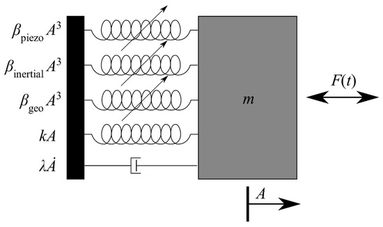
Figure 1.
Schematic picture of a piezoelectrically actuated micro-oscillator with force F(t) and mass m. The moving mass is attached to a fixed anchorage via a linear damper and four springs representing the linear and the three nonlinear restoring forces.
This nonlinear differential equation can be solved by the homotopy analysis method (HAM) to derive the frequency response of the oscillating amplitude A [17]:
Depending on the sign of the nonlinear stiffness parameter β, the resonant curve tilts to the left (β < 0) or to the right (β > 0) (see Figure 2a). In terms of a mechanical oscillating system, a spring softening (β < 0) or else a spring hardening (β > 0) effect can be observed.
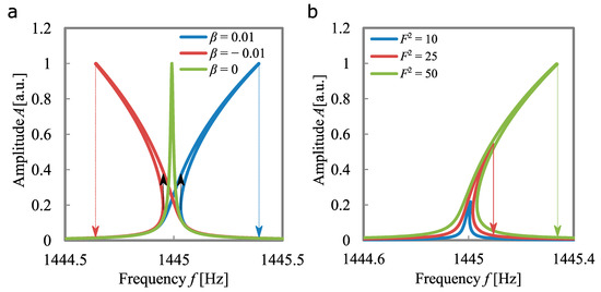
Figure 2.
Numerically simulated frequency response of a Duffing oscillator for varying stiffness coefficients (a) and for varying actuation forces (b).
Contributions to the stiffness parameter for piezoelectric oscillators are discussed in the literature and consist of three parts [18,19,20]: geometric, inertial, and piezoelectric effects. Here, the geometric part βgeo has a hardening effect, whereas the inertial component βinertial as well as the piezoelectric influence βpiezo have a softening effect:
The geometrical hardening effect is caused by the rigidity of the solid-state material at large oscillation amplitudes, which leads to a stiffening of the spring. The inertial effects appear predominant at high kinetic energies of the oscillator. The inertial effects are defined by the velocity and the acceleration on the oscillator. These effects are dominating at higher modes, due to the increase of the resonance frequency as well as the decrease of the oscillation amplitude. The piezoelectric effects originate from the nonlinear nature of the deflection of piezoelectric materials when applying high electric fields.
The solution of the Duffing equation for a given frequency is not a single-valued function. When the non-physical negative values for the amplitude are excluded, the equation leads to one (stable region of the resonance curve), two (at the jumping point) or three solutions (unstable region of the resonance curve) for the amplitude response. Within the unstable region, the amplitude exhibits abrupt jumping phenomena, depending on the sweep direction. In Figure 2a, the different sweep directions are indicated by dashed arrows. This leads to a hysteresis behaviour of the amplitude. The strength of the nonlinear effect and therefore the size of the hysteresis loop is strongly dependent on the amplitude of the driving force Fpiezo, which in turn depends on the actuation voltage. As can be seen in Figure 2b, the hysteresis gap (frequency difference between the two sweep directions) increases with increasing actuation force.
In the case of piezoelectrically driven oscillators, the actuation force Fpiezo is given by the electrically induced stress tensor σ of the aluminium nitride (AlN) thin film on the cantilever. Thus, the mechanical stress can be written in the full Voigt matrix and vector notation as:
with the piezoelectric coefficient tensor dT [21], the electric field E, which is given by the actuation voltage U, and the thickness of the AlN film t (E = U/t). In our configuration, the actuation force by the piezoelectric AlN thin film with the actuation area S can be simplified as follows:
2.2. Ayela’s Model
Due to the fact that the amplitude frequency response of Duffing oscillators is given as an implicit function (see Equation (3)), a higher numerical effort is necessary to extract the information from the resonance curve. Therefore, several approximation models have been established [13,22], to directly evaluate the key parameters out of the resonant behaviour. Important indicators include the shift of the peak frequencies, Δfup, and Δfdown, as well as the peak amplitudes of the upward sweep direction Aup, and downward sweep direction Adown (see Figure 3). Ayela et al. [13] derived an approximation for the Duffing behaviour of electrostatically excited MEMS oscillators, extracting key parameters such as the linear attenuation and the nonlinear stiffness parameter of the oscillator. In the following, the major points of the model are presented and summarised in Table 1.
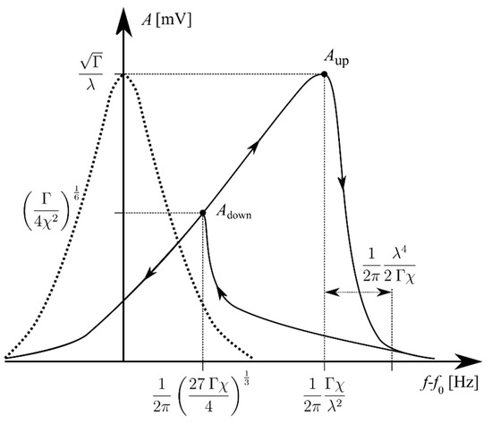
Figure 3.
Amplitude versus the frequency shift for a damped harmonic oscillator (dotted line) and Duffing oscillator (solid line). The key parameters according to Ayela’s model are included [9].

Table 1.
Listing of important parameters for characterising the behaviour of Duffing oscillators.
The frequency shift Δω caused by the Duffing effect is given by:
The gap between Aup and A ≈ 0 is given by:
with Г being the strength of the actuation, which can be calculated via the upward Amplitude Aup:
Combining the equations of the frequency shift in upward and downward directions leads to an expression for the linear damping coefficient λ:
The nonlinear damping coefficient can either be derived from the downward sweeping amplitude Adown or by fitting the slope of the frequency shifts as a function of the associated amplitude Δfup (Aup2) or Δfdown (Adown2) (see Equation (7)). The nonlinear damping coefficient χ is given as follows:
This can be related to the stiffness parameter β by using Equation (7), yielding:
This model is applied to the piezoelectric MEMS oscillator presented in this work to determine the strength of the nonlinearity.
3. Experimental Section
3.1. Manufacturing
The silicon-based micro-oscillators consisted of a single bending beam, also known as a cantilever structure, with a length of 3600 µm, a width of 1800 µm, and a thickness of 10 µm (see Figure 4a). The cantilevers were covered by an AlN thin film layer for actuation and by corresponding gold electrodes for contact. The percentage of coverage of the AlN film was varied from the whole cantilever for C_100, half of the cantilever for C_50 and a third of the cantilever for C_33 (see Figure 4b). The cantilevers were fabricated by standard microtechnology processes, including lithography, sputter deposition and wet/dry etching. A highly doped p-Si wafer (ρ = 0.01 Ωcm, boron) was chosen as substrate. At first, SiO2 was grown for electric insulation with a thickness of 120 nm in a thermal oxidation process. The SiO2 on the bottom side served as an adhesion layer for a 550 nm Si3N4 film, which was deposited by PECVD. The Si3N4 film was used as passivation layer for the KOH etching process as part of the releasing step. Both films were structured in a single lithography step using AZ 1518 resist and a subsequent etch process in 6% HF solution. The piezoelectric AlN film with a thickness of 1100 nm was deposited by reactive sputter deposition [21]. After the AlN patterns were lithographically structured, the film was etched with 85% phosphoric acid at 80 °C. The gold electrodes were deposited via DC sputtering and etched using aqua regia at 25 °C. The cantilevers were released in a two-step process. In the first step, a thin membrane was created by time-controlled KOH etching from the backside. Afterwards, the cantilevers were released from the front side using a Bosch dry etching process. In between the two steps, the KOH cavity was filled with AZ 1518 photo resist to stop the dry etching process and prevent the cantilever from suffering mechanical damage. Finally, the cantilevers were diced and cleaned with a solution of acetone, isopropanol, water and ethanol in an ultrasonic bath.
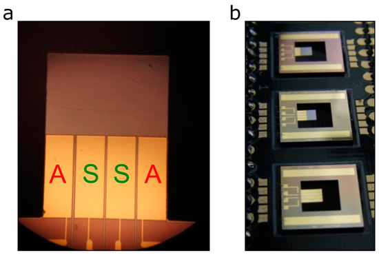
Figure 4.
Top view on the cantilever structure C_50 (a) and measurement board with the cantilevers C_33, C_50, and C_100 (from top to the bottom) (b). “A” signifies the actuation electrodes, “S” signifies the sensing electrodes.
3.2. Experimental Setup
The cantilevers were glued on top of a printed circuit board (PCB) and were electrically connected by gold wire bonds. The measurement board (compare Figure 4b) was placed within a custom-built vacuum chamber providing a pressure range from high vacuum (10−3 mbar) up to atmospheric pressure (900 mbar). Via a feedback loop, the pressure was adjusted in a dynamic equilibrium by controlling the inlet gas flow with a mass flow controller (MFC). A pure nitrogen atmosphere was chosen to provide a clean and defined measurement environment. The pressure was measured using three pressure sensors from Pfeiffer Vacuum (CMR 261/264/362) with an accuracy of <0.2%. The cantilevers were excited by a function generator decoupled with a buffer amplifier, providing a sinusoidal signal with varying amplitude and frequency. When measuring piezoelectrically driven oscillators, a parasitic crosstalk appears which can be eliminated by a compensation circuit proposed by Qiu et al. [23]. In addition to the compensation circuit, the PCB board was equipped with a charge amplifier and with an inverting amplifier. Subsequently, the resonance curves were measured by recording the compensated and amplified frequency response of the cantilever with a lock-in amplifier (SR 5210) (see Figure 5).

Figure 5.
Schematic of the experimental setup. The vacuum chamber ranges from 10−3 to 103 mbar.
4. Results
In order to investigate the possibility of using nonlinear Duffing MEMS oscillators for pressure sensing applications, the frequency response of the presented cantilever structures was recorded under varying ambient pressure conditions as well as excitation voltages. The hysteresis behaviour of the frequency response was recorded in upward (u) and downward (d) sweep direction around the peak frequency. For all AlN-layer coverage sizes the Duffing behaviour of the cantilevers was investigated up to a frequency of 120 kHz (limitation of the lock-in amplifier). The detected modes were associated with their shape by correlation with FEM eigenfrequency analysis and with recordings of a laser Doppler vibrometer (UHF-120 from Polytec).
The resonance curve of the micro-oscillator operating in the same higher mode can be seen in Figure 6. The results show hysteresis behaviour depending on both excitation voltage and ambient pressure. An increasing ambient pressure p leads to a decreasing hysteresis gap until it finally disappears (see Figure 6a,b). The influence of the ambient pressure on the frequency response is given by the linear damping coefficient λ, which increases with increasing pressure. In addition, the peak amplitude as well as the hysteresis loop become larger with increasing excitation voltage (see Figure 6c). These proportionalities are in accordance with the Duffing theory presented above (see Figure 2b). The dependency of the excitation voltage on the frequency response can be directly derived by taking Equation (6) into account.
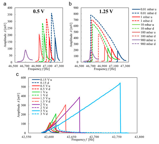
Figure 6.
Amplitude frequency response in upward (u, solid) and downward (d, dotted) sweep of the 2nd roof-tile-shaped mode of sensor C_100 for different ambient pressures and for an excitation voltage of 0.5 V (a) and 1.25 V (b), respectively. Amplitude frequency response in upward (u, solid) and downward (d, dotted) sweep of the 2nd roof-tile-shaped mode of sensor C_33 for different excitation voltages at a fixed ambient pressure of 1 mbar (c).
The presented results show the frequency response of cantilevers with different AlN-coverage sizes (33 to 100%), operated in the same mode. A difference in the eigenfrequency appears that is mainly caused by fabrication tolerances (cantilever thickness) and, to a lesser extent, by the difference of the coverage sizes of the AlN/Au stack. The presented eigenmode is the so-called second roof-tile-shaped mode, which has been found to be advantageous for operating in heavily damped environments [24] and therefore possesses relatively large oscillation amplitudes, leading to strong Duffing effects.
Interestingly, the results in Figure 6a,b indicate a spring softening effect for 100% AlN coverage, whereas a spring hardening effect occurs for a cantilever with 33% AlN coverage, but otherwise identical geometry and mode (compare Figure 6c). According to Equation (4), the nonlinearity can be divided into a geometric part, an inertial part and a piezoelectric part [18]. The geometric nonlinearity has a spring hardening effect, whereas both inertial and piezoelectric nonlinearities have a spring softening effect. This could explain why a larger coverage area of the AlN film (C_100, Figure 6a,b) can overcome the originally dominant geometric spring hardening nonlinearity (C_33, Figure 6c) and changes it into a spring softening nonlinearity. The fundamentals behind this influence of the piezoelectric coverage area on the softening/hardening behaviour require more detailed investigation, and will be analysed in a future work. Moreover, a mode-matching optimisation of the electrode shape as well as a phase-correct actuation scheme seems promising for enhancing both sensing and actuation [25].
To investigate the strength of the nonlinear Duffing effect, the frequency response was measured for the first four bending modes, and for the 2nd roof-tile-shaped mode. This was done at the best available vacuum level (10−3 mbar) to suppress the damping from the surrounding fluid. The stiffness parameter β, and the frequency shifting parameter χ (see Equations (11) and (12)) were analysed to understand the dependency of these parameters with respect to the coverage size and the mode shape. In Figure 7 the frequency shift of the peak amplitude in dependency of the squared measured amplitude is shown for both sweep directions (compare Equation (7)). The first bending mode exhibits the smallest frequency shift and biggest amplitude signal, therefore the frequency shifting parameter χ resulting from the linear fit will be the smallest. For all three coverage sizes, the frequency shifting parameter is on the same order of magnitude. The higher modes show a significantly higher frequency shift at smaller amplitudes and therefore possess a much higher value for the frequency shifting parameter. In particular, the 2nd roof-tile-shaped mode exhibits very high values, indicating a strong nonlinear Duffing effect. All results are summarised in Table 2.
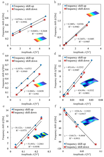
Figure 7.
Frequency shift vs. squared measured amplitude for C_33 (a), C_50 (b), and C_100 (c) in the first bending mode, C_33 in the second roof-tile-shaped mode (d), C_100 in the fourth bending mode (e) and in the second roof-tile-shaped mode (f) at 0.001 mbar. The shape of the respective eigenmodes is shown in the inserts.

Table 2.
Listing of determined key parameters for the presented sensors and mode shapes of Figure 7.
The 2nd roof-tile-shaped mode (see Figure 7d,f) shows the highest value for χ within these experiments, and therefore has been chosen for further investigations under varying ambient pressure. Additionally, the spring softening behaviour of sensor C_100 operating in this mode is an interesting aspect.
The possibility of cantilever structures exploiting Duffing effects for pressure sensing purposes was investigated by recording the frequency response under a defined pressure (see Figure 6). The amplitude was measured in both sweep directions for different excitation voltages. In the following, the resonance curves are analysed regarding their peak amplitudes and peak frequencies in upward and downward sweep directions. It turned out that the best correlation between measurement and ambient pressure could be achieved by the shift of the peak frequencies in upward direction in the case of hardening effects, and shift of the peak frequencies in downward direction in the case of softening effects, respectively (see Figure 8a,c). Thereby, the shift is related to the resonance frequency of the linear oscillator, which can be measured by applying a lower excitation voltage where no nonlinear effects occur.
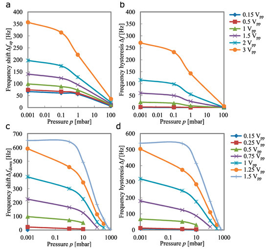
Figure 8.
Frequency shift caused by the Duffing effect in dependency of the ambient pressure for the 2nd roof-tile-shaped mode of C_33 (a) and C_100 (c) for varying excitation voltages. Frequency hysteresis between the sweep directions in dependency of the ambient pressure for the 2nd roof-tile-shaped mode of C_33 (b), and C_100 (d) for varying excitation voltages.
The best results in the sense of maximum sensitivity were obtained by cantilever C_100, with an excitation voltage of 1.5 Vpp. A linear frequency shift of 648 Hz was measured over three pressure decades, resulting in a sensitivity of 216 Hz/decade. Normalised to the resonant frequency of 47.4 kHz, this means a frequency shift of 0.46%/decade in linear approximation. By decreasing the excitation voltage, the saturation effect can be delayed. Thus, the measurement range increases at the expense of sensitivity. Depending on the application, a reasonable compromise between sensitivity and measurement range can be adjusted by choosing an appropriate excitation voltage. Furthermore, the size of the hysteresis loop, given by the difference of the peak frequencies in both directions, is strongly affected by the ambient pressure (see Figure 8b,d). Qualitatively, this measurement shows the same behaviour as the peak frequency. The absolute values are smaller because the shift in the other sweep direction is subtracted, and therefore the sensitivity (change of measurement value with pressure) is slightly smaller. An advantage of this measurement principle could be that environmental factors such as temperature effects or long-term drift effects influencing the resonance frequency can be cancelled out more easily [26,27,28,29]. Other parameters, such as, e.g., peak amplitudes, are also affected by the ambient pressure [8], but the absolute change is relatively small and more difficult to detect. For this reason, the frequency measurement is preferable. A measurement series investigating the stability of the frequencies results in a standard deviation of 2.6 Hz (corresponding to 56 ppm), and therefore provides a reliable measure for detecting the ambient pressure.
A comparison with results obtained in previous works is shown in Table 3, ranking the performance of the presented AlN nonlinear micro-oscillator. Since the plot in Figure 8 is on a logarithmic scale, a nonlinear behaviour to the measured variable, the ambient pressure, can clearly be seen. Thus, it can be deduced that the sensitivity decreases with increasing pressure, when linearising this value for the individual pressure decades. The results indicate that the sensitivity related to the resonance frequency is exceeding the values obtained in the previous works, for nearly all pressure ranges, or else it is at least comparable. A special feature is the wide measurement range down to the high vacuum regime where most mechanical sensor principles have their limitations. In this low-pressure area, our sensor exhibits its highest sensitivity.

Table 3.
Comparison of the key parameters for different pressure sensing systems.
In the next steps, the gas type dependence will be investigated by characterising the sensor under different gas atmospheres as well as the temperature influence of the measurement principle. A further work which investigates the nonlinear effect of different geometries and modes to optimise the sensor response can already be found in [36].
5. Conclusions
In this study, we analysed the frequency response of a cantilever structure with different piezoelectric AlN coverage sizes. The resonance behaviour was investigated with a focus on the nonlinear Duffing effect. The strength of the nonlinearity was experimentally identified, and the Duffing parameters were determined for each AlN coverage size and for each eigenmode. Based on these results, the 2nd roof-tile-shaped mode, which was found to be the best mode according to the stiffness parameters, was selected for pressure measurements over a wide range of six decades. The quantity with the strongest correlation to the ambient pressure was found to be the frequency shift of the peak amplitude. For the 2nd roof-tile-shaped mode, a maximum sensitivity of 0.29%/mbar for the high-vacuum regime was experimentally found. In addition, the influence of the excitation voltage was shown, revealing the possibility of adjusting the sensitivity and measurement range depending on the specific application. Compared to the other measurement principles presented in the paper, the frequency shift induced by the Duffing effect of piezoelectrically actuated MEMS oscillators offers a significantly higher sensitivity, exceeding existing work, especially in the high-vacuum range.
The current state of the art for high-dynamic-range pressure sensing in vacuum chamber applications usually requires a combination of several high cost sensors (e.g., Pirani and membrane). The new principle introduced in this work, using the Duffing-effect-induced frequency shift of a micro-oscillator to obtain high-quality pressure measurements, opens up an opportunity for a new class of wide range vacuum sensors, which can be fabricated in a much more cost-effective way. Alternatively, the size of the hysteresis loop can also be exploited with the same type of sensor, giving the advantage of reducing environmental factors such as temperature effects or long-term drift. In future work, the fundamentals behind the strong Duffing effect of the selected mode need to be clarified more precisely, as well as the influence of the actuator coverage size on the spring softening or spring hardening behaviour.
Author Contributions
Investigation, T.Z. and M.S.; Data curation, T.Z.; Project administration A.A. and H.S.; Funding acquisition A.A. and H.S., Writing- original draft T.Z. and H.S.; Writing – review & editing, T.Z. and H.S. All authors have read and agreed to the published version of the manuscript.
Funding
This research was funded by the German Science Foundation (DFG) within the grant SE 1425/14-1.
Institutional Review Board Statement
Not applicable.
Informed Consent Statement
Not applicable.
Data Availability Statement
Data available on request.
Acknowledgments
We thank Frank Tiefensee and Jorge Oevermann from the Fraunhofer Society for providing access to the laser vibrometer.
Conflicts of Interest
The authors declare that there is no conflict of interest.
References
- Aikele, M.; Bauer, K.; Ficker, W.; Neubauer, F.; Prechtel, U.; Schalk, J.; Seidel, H. Resonant accelerometer with self-test. Sens. Actuator A Phys. 2001, 92, 161–167. [Google Scholar] [CrossRef]
- Binnig, G.; Quate, C.F.; Gerber, C. Atomic force microscope. Phys. Rev. Lett. 1986, 56, 930–934. [Google Scholar] [CrossRef] [Green Version]
- Chen, S.T.; Du, S.; Arroyo, E.; Jia, Y.; Seshia, A. Utilising Nonlinear air damping as a soft mechanical stopper for MEMS vibration energy harvesting. J. Phys. Conf. Ser. 2016, 773, 012098. [Google Scholar] [CrossRef]
- Almog, R.; Zaitsev, S.; Shtempluck, O.; Buks, E. Signal amplification in a nanomechanical Duffing resonator via stochastic resonance. Appl. Phys. Lett. 2007, 90, 013508. [Google Scholar] [CrossRef] [Green Version]
- Sharma, M.; Sarraf, E.H.; Baskaran, R.; Cretu, E. Parametric resonance: Amplification and damping in MEMS gyroscopes. Sens. Actuator A Phys. 2012, 177, 79–86. [Google Scholar] [CrossRef]
- Li, Y.; Li, H.; Xiao, Y.; Cao, L.; Guo, Z. A compensation method for nonlinear vibration of silicon-micro resonant sensor. Sensors 2021, 21, 2545. [Google Scholar] [CrossRef]
- Hasan, M.; Alsaleem, F.; Oukad, H. Novel threshold pressure sensors based on nonlinear dynamics of MEMS resonators. J. Micromech. Microeng. 2018, 28, 065007. [Google Scholar] [CrossRef]
- Keskar, G.; Elliott, B.; Gaillard, J.; Skove, M.J.; Rao, A.M. Using electric actuation and detection of oscillations in microcantilevers for pressure measurements. Sens. Actuator A Phys. 2008, 147, 203–209. [Google Scholar] [CrossRef]
- Kacem, N.; Arcamone, J.; Perez-Murano, F.; Hentz, S. Dynamic range enhancement of nonlinear nanomechanical resonant cantilevers for highly sensitive NEMS gas/mass sensor applications. J. Micromech. Microeng. 2010, 20, 045023. [Google Scholar] [CrossRef]
- Green, P.L.; Worden, K.; Atallah, K.; Sims, N.D. The effect of Duffing-type non-linearities and Coulomb damping on the response of an energy harvester to random excitations. J. Intell. Mater. Syst. Struct. 2012, 23, 2039–2054. [Google Scholar] [CrossRef] [Green Version]
- Millar, S.; Desmulliez, M. MEMS ultra low leak detection methods: A review. Sens. Rev. 2009, 29, 339–344. [Google Scholar] [CrossRef]
- Martínez Rojas, J.A.; Fernández, J.L.; Sánchez Montero, R.; López Espí, P.L.; Diez-Jimenez, E. Model-based systems engineering applied to trade-off analysis of wireless power transfer technologies for implanted biomedical microdevices. Sensors 2021, 21, 3201. [Google Scholar] [CrossRef]
- Ayela, F.; Fournier, T. An experimental study of anharmonic micromachined silicon resonators. Meas. Sci. Technol. 1998, 9, 1821–1830. [Google Scholar] [CrossRef]
- Nabholz, U.; Heinzelmann, W.; Mehner, J.E.; Degenfeld-Schonburg, P. Amplitude- and gas pressure-dependent nonlinear damping of high-Q oscillatory MEMS micro mirrors. J. Microelectromech. Syst. 2018, 27, 383–391. [Google Scholar] [CrossRef] [Green Version]
- Lifshitz, R.; Cross, M.C. Nonlinear Dynamics of Nanomechanical and Micromechanical Resonators. In Review of Nonlinear Dynamics and Complexity; John Wiley & Sons: Hoboken, NJ, USA, 2008. [Google Scholar]
- Duffing, G. Erzwungene Schwingungen bei Veränderlicher Eigenfrequenz und ihre Technische Bedeutung; Vieweg & Sohn: Braunschweig, Germany, 1918. [Google Scholar]
- Tajaddodianfar, F.; Yazdi, M.R.H.; Pishkenari, H.N. Nonlinear dynamics of MEMS/NEMS resonators: Analytical solution by the homotopy analysis method. Microsyst. Technol. 2017, 23, 1913–1926. [Google Scholar] [CrossRef]
- Mahmoodi, S.N.; Jalili, N.; Daqaq, M.F. Modeling, nonlinear dynamics, and identification of a piezoelectrically actuated microcantilever sensor. IEEE ASME Trans. Mechatron. 2008, 13, 58–65. [Google Scholar] [CrossRef]
- McHugh, K.; Dowell, E. Nonlinear responses of inextensible cantilever and free–free beams undergoing large deflections. J. Appl. Mech. 2018, 85, 051008. [Google Scholar] [CrossRef] [Green Version]
- Villanueva, L.G.; Karabalin, R.B.; Matheny, M.H.; Chi, D.; Sader, J.E.; Roukes, M.L. Nonlinearity in nanomechanical cantilevers. Phys. Rev. B 2013, 87, 024304. [Google Scholar] [CrossRef]
- Ababneh, A.; Schmid, U.; Hernando, J.; Sánchez-Rojas, J.L.; Seidel, H. The influence of sputter deposition parameters on piezoelectric and mechanical properties of AlN thin films. Mater. Sci. Eng. B Solid State Mater Adv. Technol. 2010, 172, 253–258. [Google Scholar] [CrossRef]
- Davis, W.O. Measuring quality factor from a nonlinear frequency response with jump discontinuities. J. Microelectromech. Syst. 2011, 20, 968–975. [Google Scholar] [CrossRef]
- Qiu, H.; Schwarz, P.; Völlm, H.; Feili, D.; Wu, X.; Seidel, H. Electrical crosstalk in two-port piezoelectric resonators and compensation solutions. J. Micromech. Microeng. 2013, 23, 045007. [Google Scholar] [CrossRef]
- Kucera, M.; Wistrela, E.; Pfusterschmied, G.; Ruiz-Díez, V.; Manzaneque, T.; Sánchez-Rojas, J.L.; Schalk, J.; Bittner, A.; Schmid, U. Characterization of a roof tile-shaped out-of-plane vibrational mode in aluminum-nitride-actuated self-sensing micro-resonators for liquid monitoring purposes. Appl. Phys. Lett. 2014, 104, 233501. [Google Scholar] [CrossRef]
- Sanchez-Rojas, J.L.; Hernando, J.; Donoso, A.; Bellido, J.; Manzaneque, T.; Ababneh, A.; Seidel, H.; Schmid, U. Modal optimization and filtering in piezoelectric microplate resonators. J. Micromech. Microeng. 2010, 20, 055027. [Google Scholar] [CrossRef]
- Kim, B.; Candler, R.N.; Hopcroft, M.A.; Agarwal, M.; Park, W.T.; Kenny, T.W. Frequency stability of wafer-scale encapsulated MEMS resonators. Sens. Actuator A Phys. 2007, 136, 125–131. [Google Scholar] [CrossRef]
- Prikhodko, I.; Trusov, A.; Shkel, A. Compensation of drifts in high-Q MEMS gyroscopes using temperature self-sensing. Sens. Actuator A Phys. 2013, 201, 517–524. [Google Scholar] [CrossRef] [Green Version]
- Tanner, D.; Olsson, R., III; Parson, T.; Crouch, S.; Walraven, J.; Ohlhausen, J. Stability experiments on MEMS aluminum nitride RF resonators. Proc. SPIE 2010, 7592, 759209. [Google Scholar]
- Defoort, M.; Taheri-Tehrani, P.; Horsley, D.A. Exploiting nonlinear amplitude-frequency dependence for temperature compensation in silicon micromechanical resonators. Appl. Phys. Lett. 2016, 109, 153502. [Google Scholar] [CrossRef]
- Zuo, J.; Zhang, H.; Chang, Y.; Liang, J.; Pang, W.; Duan, X. Highly sensitive AlN contour-mode resonator-based pressure sensor for in-line monitoring of chemical reactions. In Proceedings of the 20th International Conference on Solid-State Sensors, Actuators and Microsystems & Eurosensors XXXIII (TRANSDUCERS & EUROSENSORS XXXIII), Berlin, Germany, 23–27 June 2019; pp. 1373–1376. [Google Scholar]
- Wang, T.; Tang, Z.; Lin, H.; Zhan, K.; Wan, J.; Wu, S.; Gu, Y.; Luo, W.; Zhang, W. A low temperature drifting acoustic wave pressure sensor with an integrated vacuum cavity for absolute pressure sensing. Sensors 2020, 20, 1788. [Google Scholar] [CrossRef] [Green Version]
- Anderås, E.; Katardjiev, I.; Yantchev, V. Lamb wave resonant pressure micro-sensor utilizing a thin-film aluminium nitride membrane. J. Micromech. Microeng. 2011, 21, 085010. [Google Scholar] [CrossRef]
- Rodríguez-Madrid, J.G.; Iriarte, G.F.; Williams, O.A.; Calle, F. High precision pressure sensors based on SAW devices in the GHz range. Sens. Actuator A Phys. 2013, 189, 364–369. [Google Scholar] [CrossRef] [Green Version]
- Han, X.; Mao, Q.; Zhao, L.; Li, X.; Li, W.; Yang, P.; Wang, Y.; Yan, X.; Wang, S.; Zhu, N.; et al. Novel resonant pressure sensor based on piezoresistive detection and symmetrical in-plane mode vibration. Microsyst. Nanoeng. 2020, 6, 95. [Google Scholar] [CrossRef]
- Shi, X.; Lu, Y.; Xie, B.; Li, Y.; Wang, J.; Chen, D.; Chen, J. A resonant pressure microsensor based on double-ended tuning fork and electrostatic excitation/piezoresistive detection. Sensors 2018, 18, 2494. [Google Scholar] [CrossRef] [PubMed] [Green Version]
- Zengerle, T.; Stopp, M.; Ababneh, A.; Seidel, H. Investigations on nonlinearities of roof-tile shape modes for pressure measurement applications. In Proceedings of the 21th International Conference on Solid-State Sensors, Actuators and Microsystems, TRANSDUCERS 21, Online, 20–25 June 2021. [Google Scholar]
Publisher’s Note: MDPI stays neutral with regard to jurisdictional claims in published maps and institutional affiliations. |
© 2021 by the authors. Licensee MDPI, Basel, Switzerland. This article is an open access article distributed under the terms and conditions of the Creative Commons Attribution (CC BY) license (https://creativecommons.org/licenses/by/4.0/).