Abstract
Ultrasonic motors employ resonance to amplify the vibrations of piezoelectric actuator, offering precise positioning and relatively long travel distances and making them ideal for robotic, optical, metrology and medical applications. As operating in resonance and force transfer through friction lead to nonlinear characteristics like creep and hysteresis, it is difficult to apply model-based control, so data-driven control offers a good alternative. Data-driven techniques are used here for iterative feedback tuning of a proportional integral derivative (PID) controller parameters and comparing between different motor driving techniques, single source and dual source dual frequency (DSDF). The controller and stage system used are both produced by the company Physik Instrumente GmbH, where a PID controller is tuned with the help of four search methods: grid search, Luus–Jaakola method, genetic algorithm, and a new hybrid method developed that combines elements of grid search and Luus–Jaakola method. The latter method was found to be quick to converge and produced consistent result, similar to the Luus–Jaakola method. Genetic Algorithm was much slower and produced sub optimal results. The grid search has also proven the DSDF driving method to be robust, less parameter dependent, and produces far less integral position error than the single source driving method.
1. Introduction
Ultrasonic motors rely on the vibration of piezoelectric actuator element at resonant frequency. For optimal operation of an ultrasonic motor, an elliptical or oblique motion is needed [1,2], which is produced through mode coupling of different vibrational modes. One example of mode coupling is the L1B2 ultrasonic motor where mode coupling occurs between the first longitudinal and second bending mode. The geometry of the actuator is adapted to generate the two modes at the same operating frequency, and different regions of the actuator are selectively driven with one or more driving source [3,4]. These motors are also known to exhibit nonlinear dynamic characteristics due to the nature of force transfer through friction, such as hysteresis and creep [5]. To minimize these nonlinearities, friction models can be built to model and linearize the behavior of piezoelectric element [6,7,8].
Different control methods can also be used to deal with the nonlinear behavior, such as a simple pulsed control relay [9], a hybrid control method of a traditional PID controller and a rule-based scheme [10], a fuzzy cerebella model articulation control (FCMAC) algorithm [11], state windows with adaptive PID [12], and recurrent fuzzy neural network algorithms [13].
The nonlinear characteristics pose a difficulty to produce exact mathematical models for ultrasonic motors [14]. In addition, some nonlinear systems can change when control is applied, so the mathematical model of the open loop system would not be beneficial for closed-loop operation [15]. Furthermore, the assembly and working conditions of each ultrasonic motor stage can require special, individualized tuning of the applied controller. The controller parameters of said controller are then manually determined, due to the nonlinear behavior of the ultrasonic motor.
In that sense, data-driven modeling and control that does not require a mathematical model of the plant offer a good alternative to model based control. Data-driven control systems are thus based on experimental data collected from the plant and can be classified into indirect data-driven control, where a mathematical model is approximated from the collected data, and direct data-driven control, to tune the controller directly from the measured data.
In the presented work, direct data-driven control is employed to control the nonlinearity of an ultrasonic motor with different driving methods. This is done with iterative feedback tuning. This method is a model free technique for the direct iterative optimization of the parameters of a fixed-order controller, a PID controller in the presented case. For iterative feedback tuning, the controller parameters are successively updated and feedback on each parameter set is collected from the standard closed-loop control system. The automatic tuning methods presented in this study offer an alternative to manual tuning needed to be carried out individually for each ultrasonic motor stage system. The tuning might also need to be repeated depending on the velocity and other working conditions influencing the friction-based principle of operation of the ultrasonic motor. In that sense, a data driven automatic tuning method is more systematic, reliable, and time efficient.
The structure of the PILine® rotary stage, on which iterative feedback tuning of PID control parameters was applied, is given in Section 2. In Section 3, single source and dual source dual frequency driving methods are summarized with motion control algorithm. Iterative feedback tuning methods, which is the main contribution in this study, is described in Section 4. After analyzing the iterative tuning methods for different motor driving techniques in Section 5, the manuscript is concluded in Section 6.
2. PILine® Rotary Stage
The data-driven control methods were tested on the U-651 rotational stage system produced by Physik Instrumente GmbH [16]. The stage is shown in Figure 1. U-651 rotational stage is a high precision positioning drive based on ultrasonic motor actuation and guided by crossed roller bearings. Optical encoder with 4 µrad (2.3 × 10⁻⁴°) resolution is integrated to measure the rotational movements.
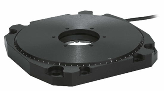
Figure 1.
U-651 PILine® rotational stage. Source: PI (Physik Instrumente).
The core elements of the rotary stage are the piezoelectric actuators that are preloaded against a movable guided ring via pusher. Actuator of the motor has a rectangular geometry with a dimension of 25 mm × 11 mm × 4 mm. The rectangular piezoelectric plate is covered with one electrode on one main surface, and sectioned into two electrodes on the other main surface. The actuator is excited at ultrasonic resonance frequencies by sinusoidal voltage waveforms, which leads to the deformation of the piezoelectric actuator causing diagonal motion of the pushers relative to the spinning ring. Preloaded springs ensure self-locking of the stage when the electric power is switched off. Two piezoelectric actuators were placed at opposite sides of the spinning ring where the direction of rotation can then be determined by selective excitation of the electrodes (see Figure 2).
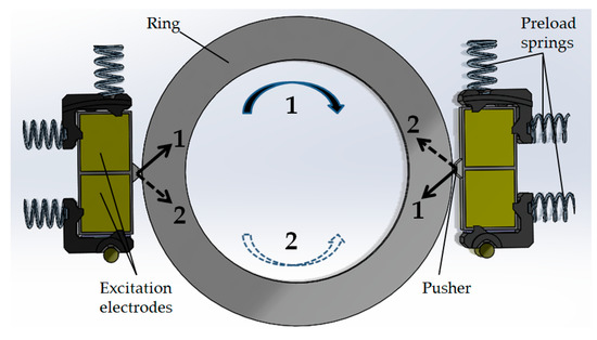
Figure 2.
Actuation in PILine® piezo rotary stage.
3. Driving Methods and Motion Control
The piezoelectric actuator of the PILine® motor can be driven in two ways: one source drive and dual source dual frequency drive (DSDF).
3.1. One Source Drive
In this case, one sinusoidal voltage as seen in Figure 3 is applied on only one of the sectioned electrodes, while the other sectioned electrode is left floating [17]. The sinusoidal signal at a suitable frequency can initiate a planar mode at the excited section of the rectangular plate. The frequency of the planar mode is about 155 kHz when the plate is free. After the piezoelectric actuator is assembled into the stage, this frequency can increase up to 3 kHz. Under single source excitation, the unexcited section and the friction coupler (pusher) act as a perturbation mass as the pusher moves in an oblique direction. The oblique motion, with normal and tangential components, is then transferred to the spinning ring through frictional interaction. Direction of motion can then be altered by changing the excited electrode, while leaving the other one floating. This driving method is very effective for obtaining high performance from an ultrasonic motor. The voltage of the sinusoidal wave depends on the desired velocity of operation, with the maximum voltage limited to 71 Vrms.
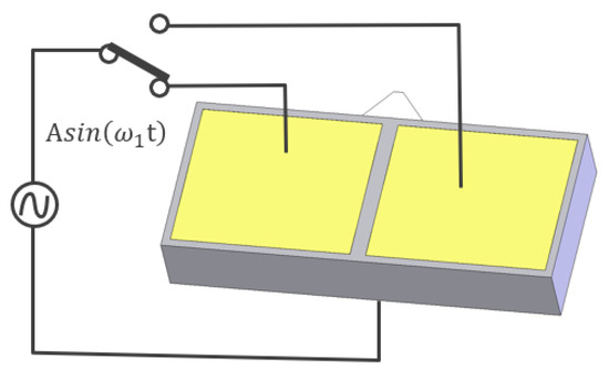
Figure 3.
One source driving of the stator. During single source drive, only one of the electrodes on the piezoelectric plate is exposed to one sinusoidal voltage at a frequency of ω1. Changing the excited electrodes changes the moving direction of the slider.
3.2. DSDF Drive
In an ultrasonic motor such as the PILine® motor, as a typical input voltage–moving speed characteristics, the low speed region is the most problematic area. Furthermore, the difference between static and dynamic friction properties also enhances the nonlinearity found in this area. To obtain movement from the piezoelectric actuator, the vibration amplitude, thus force generated by the pusher on the stator, should be larger than the static friction force. As soon as the force generated by the stator exceeds the breakaway force, a slider would be accelerated maintaining that the dynamic friction force is smaller than the static one. These kinds of start stop movements initiate friction induced forced vibrations or noises.
As these issues must be dealt with while trying to obtain slow motion from an ultrasonic motor, the dual source dual frequency driving method was introduced to enhance controllability [18].
For dual source dual frequency drive (DSDF), both electrodes of the piezoelectric actuator are electrically excited (see Figure 4). While one driving sinusoidal signal is considered the primary driving signal, with a frequency of 155 kHz (or up to 3 kHz higher) as in the case of single source drive condition. The secondary driving signal at the other electrode has a frequency 20 kHz higher. The pusher’s motion then follows a narrow elliptical path due to the primary driving signal, and the contribution of the secondary signal with a frequency around 175 kHz is only in tangential direction. The resulting pusher motion then follows a modulated elliptical trajectory. Another interesting feature here is that the servo control frequency is synchronized to the frequency difference of the two driving signals. More information on dual source dual frequency driving method can also be found in previous studies [18,19,20].
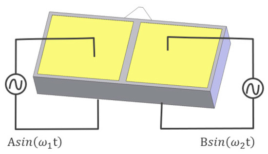
Figure 4.
Dual-source-dual-frequency (DSDF) driving of the stator. Both electrodes on the piezoelectric plate are exposed to sinusoidal voltage signals at different frequencies (ω1 and ω2) and different magnitudes (A and B).
The DSDF driving method allows for a silent and smooth motion at low velocities, decreasing the positioning error of linear movement to less than 10 nm for velocities from 1.0 mm/s to 0.001 mm/s.
Iterative feedback tuning methods are applied on both single and DSDF driven ultrasonic motors servo motion control and a comparison was run between them to investigate the best tuning method for each. In the next section, various tuning methods are presented and explained in detail.
3.3. Motion Control
The rotary stages were driven by C-867.2U2 controller, a PID servo controller with an offset [21]. As shown in Figure 5, the error signal goes through a specific operation with every PID parameter to form the control input. The parameter is multiplied by the error, the parameter integrates the error to take past values into consideration, and the parameter examines the error rate of change to predict future values. The PID controller parameters , and can be tuned to produce a suitable control response for each ultrasonic motor stage system and its working condition.
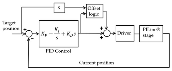
Figure 5.
PID motion control algoritm of PILine® stage.
Due to the high non-linearity of the system, a mathematical model for piezoelectric ultrasonic motors that can be used for model-based control is difficult to obtain. As ultrasonic motors rely on friction forces for their operation, they are affected by factors such as temperature, humidity, and velocity of operation. In that sense, data-driven modeling and control that does not require a mathematical model of the plant offer a good alternative to model-based control. Though a simple PID controller is applied to control the ultrasonic motor, it is challenging to tune the PID parameters as in a linear system, because of the non-linear nature of the ultrasonic motor. Thus, direct data driven control methods offer an alternative to manual tuning to account for the nonlinear behavior of the ultrasonic motor.
Data-driven control systems are based on experimental data collected from the plant, either to approximate the mathematical model from the collected data, or to design the controller directly from the measured data. The distinction between the two options classifies data-driven control methods into two types: (1) indirect methods that are carried out in two steps, first identifying the model, then designing the controller based on the identified parameters; (2) direct methods that offer a solution to the problems posed by indirect methods by mapping the experimental data to directly tune the controller, without having an identified model in between. The distinction between the two concepts can be seen in Figure 6.
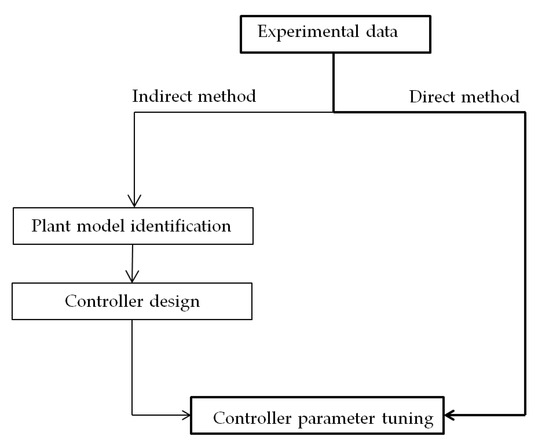
Figure 6.
Data-driven control methods.
4. Iterative Feedback Tuning Methods
The goal of direct data-driven control is iterative feedback tuning to find the optimal parameters for the PID controller for driving the piezoelectric ultrasonic motor. This method is a model-free technique for the direct iterative optimization of the parameters of a fixed-order PID controller. The best parameters are selected based on various criteria expressed in a fitness function. The fitness function is chosen to be integral performance criteria, which is calculated from the step response of each step of the ultrasonic motor by integrating the process error. The most commonly used PID controller integral performance index is the absolute Integral-Squared-Error (ISE) [22], calculated as Equation (1)
where is the difference between the commanded and actual position of the stage, and and are the start and end time of the constant velocity portion of the trajectory, respectively (Figure 7). Integral-Squared-Error has a unit of for rotational stages. Summation value of the absolute deviation is used for the calculation of the function (Figure 8).

Figure 7.
Trajectory and actual motor position with (a) deviation, (b) actual velocity.

Figure 8.
Trajectory and actual motor position at velocity of 0.2 °/s with summation of absolute value deviations.
Fitness function value for the evaluation of the PID tuning expressed in Equation (2) is reciprocal of Integral Squared Error (ISE).
First, a grid search is run with the two driving methods as a reference for the tuning methods. Grid search is considered an exhaustive search parameter optimization method where all possible parameter combinations are evaluated. The limits of the search space of the grid search are marked with maximum and minimum values of the P, I, and D parameters. The solution vector containing the P, I and D values is then evaluated with the fitness function. In the results section, the fitness values of all PID parameters within the given search space can be seen in a scatter plot. The resulting scatter plots will allow for patterns in the search space to be found and the validity of the other tuning methods to be examined. As well as showing how the optimal parameters vary with respect to different stage systems, velocities, and driving methods.
Another tuning algorithm applied is the Luus–Jaakola algorithm. The Luus–Jaakola algorithm was developed as an optimization method for non-linear problems in 1973 by Rein Luus and T H. Jaakola [23]. As a simple, straightforward parameter optimization method, the Luus–Jaakola algorithm does not require complex calculations. Yet, it was proven to be effective in many optimization purposes, including model reduction [24], finding solutions for nonlinear system equations [25], and in PID-controller tuning [26], as will be used in the presented study.
By using the Luus–Jaakola algorithm, a number of randomly generated solution candidates for each iteration is evaluated. Based on the best solution of those tested, the search space is modified to include only random numbers within a smaller search space. The new random solutions are generated within a certain range from the optimal solution of the previous iteration. As the number of iterations progress, the search space gets smaller and smaller, until a certain termination condition is reached, namely, how small the search space is.
A hybrid method based on both the Luus–Jaakola method and grid search was newly developed, where the search region is narrowed down and the density of the grid is increased as the iterations progress. As shown in Figure 9, the algorithm starts with a very sparse grid and a large step between the candidate solutions in the first step. Then the best solution is found for the first iteration and two processes take place based on that solution. The search space is made smaller and fitted around the optimal solution found, and the step size is also made smaller so that more solutions are evaluated in closer proximity to each other. The rate at which the search space is shrinking is determined by the parameter. The process carries on with the same sequence for many iterations. The number of candidate solutions in each iteration remains the same throughout the process, but the search space is narrowed down and more thoroughly inspected for the optimal solution as iterations progress [27].
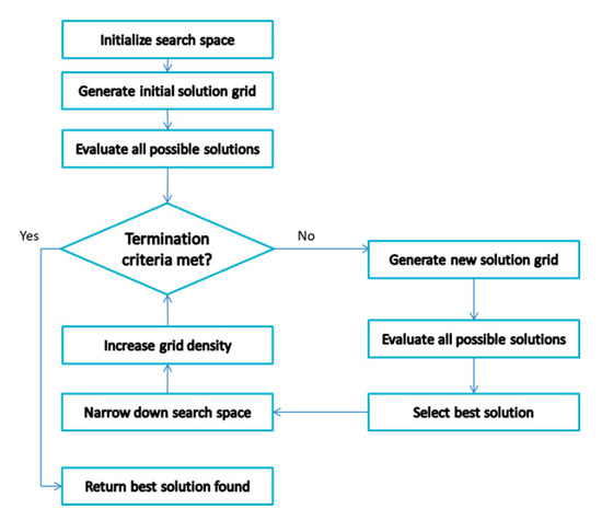
Figure 9.
Flow chart of Hybrid Grid Luus–Jaakola method.
Another method used for tuning was genetic algorithm. Genetic algorithm lies among the evolutionary methods for parameter optimization and is a method for the global optimization of black-box functions. The algorithm’s name is inspired by the biological concept of evolution, as it relies mainly on three genetic operations that evolving genes undergo, namely, selection, crossover, and mutation.
The genetic algorithm carries out the selection process across iteration steps called generations. All the candidate solutions in a single generation are called a population. In each generation, the population’s performance is evaluated based on specific criteria represented in the fitness function. In the next iteration, when the new generation is being formed, the new solutions are selected with a probability that matches their relative fitness compared to the rest of the old population. In natural selection, it is so that good individuals, good solutions in this case, have more chances of being reproduced in the next generation [28].
5. Results and Analysis
As a starting point to the optimization problem presented, a grid search for the optimal PID parameters was run on the U-651 rotation stage. The test was run four times, with both single source driving and DSDF driving methods and with rotational velocities 0.1 °/s and 2.0 °/s. As detailed in the previous section, the fitness function expresses the inverse of integrated square error throughout the constant velocity section of each step taken by the stage; the calculation also excludes the portion at the beginning of motion where actual position has not yet caught up with the commanded position. The graphs to be shown were made with the help of python open source graphing library [29].
The plot in Figure 10 shows the variation of the fitness function value across different P, I, and D parameters while the stage is driven with the DSDF driving method at the velocity of 0.1 °/s. The size and color of the scatters in the scatter plot indicates the fitness function value of this specific combination of PID parameters. The fitness function values are used for the color grading as it shows the variation more clearly, and bigger scatter points have a higher fitness function value. From the plot, it is clear that there are a few optimal values, and the best ones are concentrated where the highest I and P values are.
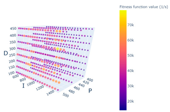
Figure 10.
Grid search with fitness function values for the velocity of 0.1 °/s and DSDF source driving.
The test run with the same velocity of 0.1 °/s using the single source driving method shows vastly different results. The fitness function value peaks at 14,000, which is about one-fifth of the value achieved with the DSDF driving method (see Figure 11).
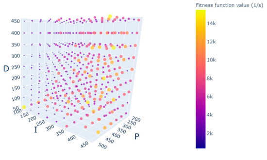
Figure 11.
Grid search with fitness function values for the angular velocity of 0.1 °/s and single source driving.
With higher velocities up to 5.0 °/s, the DSDF driving method also offers better results. The plot in Figure 12 below shows the fitness value variation with 2.0 °/s angular velocity. A similar pattern is seen to that of the lower velocity. The optimal values are multiple and concentrated in a certain region. A clear difference is seen between the optimal parameters for the same stage using the same driving method but with different angular velocities. Rather than having fixed PID controller parameters for a stage across all possible operating velocities and conditions, data driven control methods would allow the possibility to tune the PID parameters specifically for a certain operating velocity and conditions, given how they vary as seen in the scatter plots. Moreover, the range of PID parameters at slow velocities with DSDF driving method is wider as compared to single source drive.
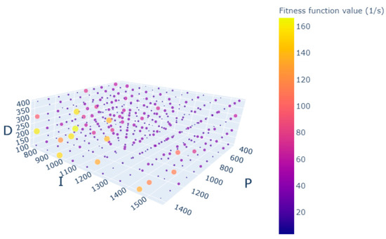
Figure 12.
Grid search with fitness function values for the angular velocity of 2.0 °/s and DSDF source driving.
As for the single source driving method, the optimal value is also found at fewer points. The fitness function value of the optimal point is also low compared to that of the DSDF driving. The fours plots show a clear superiority of the DSDF driving method (Figure 10, Figure 11, Figure 12 and Figure 13).
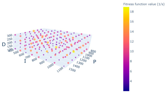
Figure 13.
Grid search with fitness function values for the angular velocity of 2.0 °/s and single source driving.
After discussing the grid search results of the two driving methods, different search methods can be examined and compared against the grid search results as a reference. The search methods are also compared against each other in terms of minimum function value reached and rate of convergence, as in how many iterations are needed to reach a certain function value. For the three search methods, genetic algorithm, Luus–Jaakola and the hybrid grid search–Luus–Jaakola method, the convergence curves offer good insights into the behavior of each method.
For the single source driving method with a velocity of 2.0 °/s, the hybrid method is shown to converge faster than the Luus–Jaakola algorithm, but converges to a slightly higher value. The genetic algorithm initially converged to an even higher value and took 25 iterations to reach a lower value, compared to around 14 iterations for the other two methods (see Figure 14).
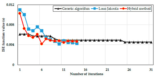
Figure 14.
Tuning methods comparison for single source driving.
As for the DSDF driving method with a velocity of 2 °/s, there was a clear variation between the convergence curve of the genetic algorithm and that of the other two methods. The hybrid method also converged faster and converged to the lowest value, while the genetic algorithm’s optimal value was much higher than that of the other two methods, and it was only reached after 26 iterations (see Figure 15).
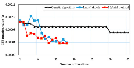
Figure 15.
Tuning methods comparison for DSDF driving.
The optimal PID parameters found for both the single source and DSDF driving using different search methods are shown in Table 1. As seen, the Luus–Jaakola and hybrid methods show similar results for both single source and DSDF driving methods, while genetic algorithm is not as similar. The seen patterns are also reflected in the convergence curves and how the optimal PID parameters fluctuate in each search iteration.

Table 1.
Optimal PID parameters and corresponding ISE function values for two driving methods performed with various search algorithms at 2 °/s velocity.
As clearly seen from the convergence curves on Figure 14 and Figure 15, the value reached with the DSDF driving method are much lower than those with the single source driving. This can also be confirmed by the grid searches run with both methods. For clearer comparison, the convergence curves of the hybrid grid search–Luus–Jaakola method at velocity 1.0 °/s are shown in Figure 16. The values of the single source driving method are shown on the primary axis, and those of the DSDF driving method are shown on the secondary axis. The value in the single source driving case is several 100 times that from the DSDF driving.
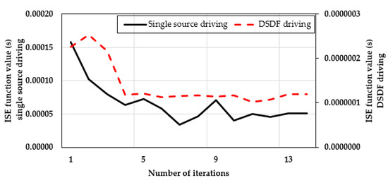
Figure 16.
Convergence curve comparison at velocity 1.0 °/s.
When testing the hybrid grid search–Luus–Jaakola algorithm with different velocities, the values of the single source and DSDF driving methods can be compared. The values of the single source driving method are much higher than that of the DSDF driving method in all of the velocities, but the relative difference between the error of the two driving methods goes lower as the velocity increases. As seen in Figure 17, the difference is more prominent in lower velocities where the DSDF driving method proves to be most efficient.
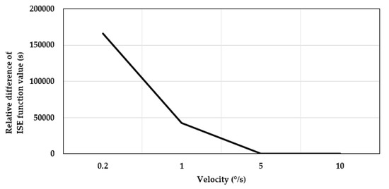
Figure 17.
Relative difference between ISE of optimal parameters of driving methods.
As a final comparison between the single source and the DSDF source driving methods, response of constant velocity trajectory with the optimal found PID parameters for both driving methods is shown in Figure 18.
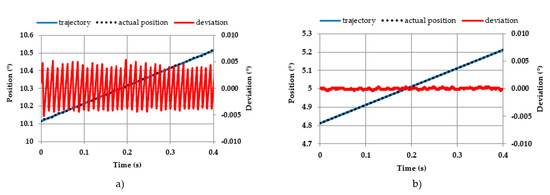
Figure 18.
Response of constant velocity trajectory with the optimal PID parameters at 1.0 °/s with (a) single source driving and (b) DSDF driving.
6. Conclusions
In this study, a direct data-driven control method was utilized in running iterative feedback tuning of the PID controller parameters for a rotational microscope stage system powered by an ultrasonic motor driven with two different driving methods, single source and DSDF driving.
For iterative feedback tuning, three learning-based methods were used and a comparative analysis was run between them. The three learning-based methods are genetic algorithm, the Luus–Jaakola algorithm, and a newly developed algorithm that is a hybrid between grid search and the Luus–Jaakola algorithm—a grid search with systematic reduction of the search space and the sampling step size. After the three methods were compared in terms of accuracy and time efficiency, it was found that the hybrid method proposed in this work converged faster with both driving methods, offering similar results to the Luus–Jaakola method in terms of accuracy. The genetic algorithm, on the other hand, was shown to be the least effective and time efficient for both driving methods.
The grid search results from the two driving methods were also compared, where it was found that the DSDF driving method is more robust, less parameter dependent, and produces far less integral position error than the single source driving method. On the other hand, the single source driving method is more parameter-dependent and produces far more integral position error than the DSDF driving method. The DSDF driving method appears to be ideal for obtaining smooth motion at low velocities.
The applied data-driven control method has proved to be an effective alternative to manual tuning for ultrasonic motor rotational stage systems. As the manufacturing and assembly conditions of each stage system results in different tuning requirements, as well as the changes in working conditions and velocity of operation, the controller parameters of each stage need to be tuned accordingly, and the tuning process needs to be repeated as the working conditions change. Data-driven control methods have allowed for a reliable automatic tuning process to deal with the ultrasonic motor’s non-linearity and further establish the validity of the DSDF driving method at a low velocity.
Author Contributions
Conceptualization, S.M. and B.D.; methodology, S.M. and B.K.; software, S.M.; validation, S.M. and B.D.; formal analysis, S.M.; investigation, S.M., B.D. and B.K.; resources, B.D. and B.K.; data curation, S.M.; writing—original draft preparation, S.M.; writing—review and editing, B.D. and B.K.; visualization, S.M.; supervision, B.D. and B.K.; project administration, B.D. All authors have read and agreed to the published version of the manuscript.
Funding
This research received no external funding.
Institutional Review Board Statement
Not applicable.
Informed Consent Statement
Not applicable.
Data Availability Statement
Not applicable.
Conflicts of Interest
The authors declare no conflict of interest.
References
- Uchino, K. Piezoelectric ultrasonic motors: Overview. Smart Mater. Struct. 1998, 7, 273–285. [Google Scholar] [CrossRef]
- Zhao, C. Ultrasonic Motors, Technologies and Applications; Springer: Berlin/Heidelberg, Germany, 2011. [Google Scholar] [CrossRef]
- Delibas, B.; Koc, B. L1B2 piezo motor using D33 effect. In Proceedings of the 16th International Conference on New Actuators, Bremen, Germany, 25–27 June 2018; pp. 1–4, ISBN 978-3-8007-4675-0. [Google Scholar]
- Tomikawa, Y.; Takano, T.; Umeda, H. Thin Rotary and Linear Ultrasonic Motors Using a Double-Mode Piezoelectric Vibrator of the First Longitudinal and Second Bending Modes. Jpn. J. Appl. Phys. 1992, 31, 3073–3076. [Google Scholar] [CrossRef]
- Seemann, W.; Arockiarajan, A.; Delibas, B. Modeling and simulation of piezoceramic materials using micromechanical approach. In Proceedings of the European Congress on Computational Methods in Applied Sciences and Engineering (ECCOMAS), Jyväskylä, Finnland, 24–28 July 2004. [Google Scholar]
- Minase, J.; Lu, T.; Cazzolato, B.; Grainger, S. A review, supported by experimental results, of voltage, charge and capacitor insertion method for driving piezoelectric actuators. Precis. Eng. 2010, 34. [Google Scholar] [CrossRef]
- Sato, M.; Yoshida, N.; Fukai, I. Equivalent Circuit of Piezoelectric Transducers with Spatially Nonuniform Properties. Jpn. J. Appl. Phys. 1990, 29 (Suppl. 1), 62. [Google Scholar] [CrossRef]
- Deng, Y.; Zhao, G.; Yi, X.; Xiao, W. Comprehensively modeling and parametric identification for speed prediction of L1B2 ultrasonic motor. J. Phys. Conf. Ser. 2020, 1449, 012007. [Google Scholar] [CrossRef]
- Afonin, S.M. Pulsed control of nano and micro piezomotors. Russ. Eng. Res. 2013, 33, 89–90. [Google Scholar] [CrossRef]
- Mrad, R.; Abhari, A.; Zu, J. A control methodology for an inchworm piezomotor. Mech. Syst. Signal Process. 2003, 17, 457–471. [Google Scholar] [CrossRef]
- Fan, K.; Lai, Z. An intelligent nano-positioning control system driven by an ultrasonic motor. Int. J. Precis. Eng. Manuf. 2008, 9, 40–45. [Google Scholar]
- Delibas, B.; Koc, B.; Thielager, J.; Stiebel, C. A novel drive and control method for piezoelectric motors in microscopy stages. In Proceedings of the Euspen’s 21st International Conference & Exhibition, Copenhagen, Denmark, 7–10 June 2021. [Google Scholar]
- Rho, J.; Kim, B.; Lee, C.; Joo, H.; Jung, H. Design and characteristic analysis of L1B4 ultrasonic motor considering contact mechanism. Trans. Ultrason. Ferroelectr. Freq. Control 2005, 52, 2054–2064. [Google Scholar] [CrossRef]
- Maslan, M.; Jamaludin, Z.; Rahman, M.A.A.; Abdullah, L.; Abd Latib, M.L.; Karjanto, J.; Mailah, M. Development of System Identification for Piezoelectric Patch Actuator. Appl. Mech. Mater. 2015, 761, 245–249. [Google Scholar] [CrossRef]
- Kutz, J.; Brunton, S.; Brunton, B.; Proctor, J. Dynamic Mode Decomposition: Data-Driven Modeling of Complex Systems; SIAM-Society for Industrial and Applied Mathematics: Philadelphia, PA, USA, 2016; ISBN 978-1-611974-49-2. [Google Scholar]
- Physik Instrumente GmbH Co. & KG. Available online: https://www.physikinstrumente.com/en/products/miniature-stages/miniature-rotation-stages/u-651-rotation-stage-with-low-profile-design-703071/ (accessed on 6 January 2021).
- Vyshnevskyy, O.; Kovalev, S.; Wischnewskiy, W. A novel, single-mode piezoceramic plate actuator for ultrasonic linear motors. IEEE Trans. Ultrason. Ferroelectr. Freq. Control 2005, 52, 2047–2053. [Google Scholar] [CrossRef] [PubMed]
- Delibas, B.; Koc, B. A Method to Realize Low Velocity Movability and Eliminate Friction Induced Noise in Piezoelectric Ultrasonic Motors. IEEE/ASME Trans. Mechatron. 2020, 25, 2677–2687. [Google Scholar] [CrossRef]
- Koc, B.; Delibas, B. Method for Closed-Loop Motion Control for an Ultrasonic Motor. US Patent 16/633,940, 25 June 2020. [Google Scholar]
- Koc, B.; Von Deyn, L.; Delibas, B. Dual source dual frequency drive and modeling of resonance type piezoelectric motor. In Proceedings of the International Conference and Exhibition on New Actuators and Drive Systems, online, 17–19 February 2021; pp. 62–65. [Google Scholar]
- Physik Instrumente GmbH, Co. & KG. Available online: https://www.physikinstrumente.com/en/products/controllers-and-drivers/controllers-drivers-for-piezomotors/c-8672u2-piline-motion-controller-412418438/ (accessed on 6 January 2021).
- Argo, B.; Hendrawan, Y.; Riza, D.; Laksono, A. Optimization of PID Controller Parameters on Flow Rate Control System Using Multiple Effect Evaporator Particle Swarm Optimization. Int. J. Adv. Sci. Eng. Inf. Technol. 2015, 5, 60–68. [Google Scholar] [CrossRef]
- Luus, R.; Hennessy, D. Optimization of Fed-Batch Reactors by the Luus-Jaakola Optimization Procedure. Ind. Eng. Chem. Res. 1999, 38, 948–1955. [Google Scholar] [CrossRef]
- Luus, R. Optimization in model reduction. Int. J. Control 1980, 32, 741–747. [Google Scholar] [CrossRef]
- Sacco, W.; Henderson, N. Finding all solutions of nonlinear systems using a hybrid metaheuristic with Fuzzy Clustering Means. Appl. Soft Comput. 2011, 11, 5424–5432. [Google Scholar] [CrossRef]
- Rathore, N.; Singh, V.; Chauhan, D. ISE based PID controller tuning for position control of DC servo-motor using LJ. In Proceedings of the International Conference on Signal Processing, Computing and Control (ISPCC), Solan, India, 24–26 September 2015; pp. 125–128. [Google Scholar] [CrossRef]
- Makarem, S. Advanced Driving and Motion Control of Multiple Piezo Motors. Master Thesis, University of Oviedo, Oviedo, Spain, 2020. [Google Scholar]
- Skiena, S. The Algorithm Design Manual; Springer-Verlag: London, UK, 2012; ISBN 978-1-84800-070-4. [Google Scholar]
- Plotly Technologies Inc. Collaborative Data Science. Montréal, QC, Canada, 2015. Available online: https://plot.ly (accessed on 11 January 2021).
Publisher’s Note: MDPI stays neutral with regard to jurisdictional claims in published maps and institutional affiliations. |
© 2021 by the authors. Licensee MDPI, Basel, Switzerland. This article is an open access article distributed under the terms and conditions of the Creative Commons Attribution (CC BY) license (https://creativecommons.org/licenses/by/4.0/).