1. Introduction
A permanent magnet synchronous motor (PMSM) has the advantages of having a simple structure, a small moment of inertia, a fast dynamic response, and high power density [
1]. PMSMs are extensively used in machine tools, robots, automobiles, medical treatment, aviation, and aerospace [
2,
3,
4]. The performance of a system actuated by a PMSM is largely dependent on its control. Therefore, many controllers have been developed to control PMSMs, such as proportional integral derivative (PID) control, sliding mode control, adaptive control, active disturbance rejection control (ADRC), and intelligent control [
5,
6,
7,
8,
9]. PID control is used most often. However, a short response time and small overshoot are hard to be fulfilled at the same time in PID control. What’s more, the disturbance rejection ability of PID control is weak [
10,
11]. Therefore, the nonlinear control of PMSMs is of great interests to researchers.
ADRC is a nonlinear control inherited from PID proposed by Jingqing Han from the Chinese Academy of Sciences [
12]. ADRC proves to be a capable replacement of PID with unmistakable advantages in performance and practicality, providing solutions to the pressing engineering problems of today [
13,
14]. ADRC combined with sliding mode control was proposed to improve the stability of a system with disturbance [
15]. In [
16], ADRC was applied to the speed control of a PMSM, thus yielding the ideal control effect. Reference [
17] used linear ADRC to control a five-phase PMSM and applied it to the drive systems of electric vehicles. In [
18], a first-order ADRC was applied to a position servo system to improve the positioning accuracy. The predictive function and the extended state observer have been applied to the PMSM speed control to improve robustness [
19]. In [
20,
21], a third-order ADRC model was proposed and applied to the position control of a PMSM, while first-order ADRC was applied in the speed and current control loop in [
22]. First-order ADRC has been used to replace the speed loop PI controller; however, its control accuracy was demonstrated to depend on the observation accuracy of the extended state observer (ESO) [
23,
24]. In [
25,
26], to simplify the structure of nonlinear ADRC, linear ADRC is used in the PMSM control to improve disturbance rejection ability. The abovementioned literature shows that ADRC is extensively used in PMSM control.
ADRC primarily includes a tracking differentiator (TD), an extended state observer (ESO), and a nonlinear state error feedback (NLSEF). The fal(∙) functions in the ESO and NLSEF are nonlinear. There is an inflection point close to the origin of the fal(∙) function, leading to the chattering problem of ADRC and adversely affecting the accuracy and robustness of the system. To improve the control performance of ADRC, an improved nonlinear newfal(∙) function, based on the Sigmoid function, is proposed and a first-order improved ADRC is constructed. Firstly, the mathematical model of a PMSM is built. Secondly, the improved first-order TD, ESO, and NLSEF are designed. The equations of each part of the improved first-order ADRC are provided, and an improved first-order ADRC is constructed. The Lyapunov stability of the first-order TD, the second-order ESO, and the system are analysed. Finally, the improved ADRC (I-ADRC) is used in the speed control loop of the PMSM in simulation and experiment. The results show that I-ADRC has stronger disturbance rejection ability and stability than the PI and ADRC controller.
2. Mathematical Model of PMSM
Both the stator and the rotor of a PMSM are coupled with an air gap magnetic field, leading to a complex electromagnetic relationship. To simplify the analysis without affecting the control performance, the following assumptions are made:
- (1)
The saturation of the iron in the stator of the motor is ignored;
- (2)
The effects of the eddy current and hysteresis are ignored;
- (3)
The three phase windings of the stator are symmetrical.
The mathematical model of a PMSM comprises the voltage equation, flux linkage equation, electromagnetic torque equation, and mechanical equation [
27,
28]. When the vector control strategy is applied, the mathematical model of a PMSM can be written as
where
ud,
uq,
id,
iq,
Ld,
Lq,
ψd, and
ψq are the voltage, current, inductance, and flux linkage in the d-q reference frame,
is the phase resistance, and
ψf is the flux linkage of the permanent magnet.
Te and
TL are electromagnetic torque and load torque, respectively.
B is the damping coefficient of the rotor and load,
pn is the pole number,
J is the rotor moment of inertia, and
ω is the rotational speed of the motor.
The relationship between Te and iq, ω can be obtained from Equation (1). First-order ADRC in this study is used to better control iq and improve the performance of the speed loop.
For a surface mounted PMSM,
Ld =
Lq =
Ls is fulfilled. When
id is set to 0 in field-oriented control, the torque equation in (1) changes to
The speed equation of the PMSM is then obtained from (1) and (2)
3. I-ADRC Design of PMSM
ADRC takes the internal and external disturbances, and the unmodeled part of the system as the total disturbance. The ESO is developed according to the input and output of the system. The total disturbance is estimated online, and compensated in the feedback control [
29,
30].
The primary function of the TD in ADRC is to realise the fast tracking of the target signal without overshoot. The ESO observes the total disturbances for compensation to improve the disturbance rejection ability of the system. The NLSEF compares the target signal and its differentiation from the TD and the system output and its differentiation from the ESO, and then the control signal is generated according to the obtained error [
31,
32].
For the first-order system [
33],
Let
,
, the extended second-order system of Equation (4) is as follows:
where
is the system state variable,
is the disturbance, where
and
,
is the differential of the disturbance,
is the control variable, and
is the gain coefficient.
Match Equations (3) and (5), then
,
,
,
, and
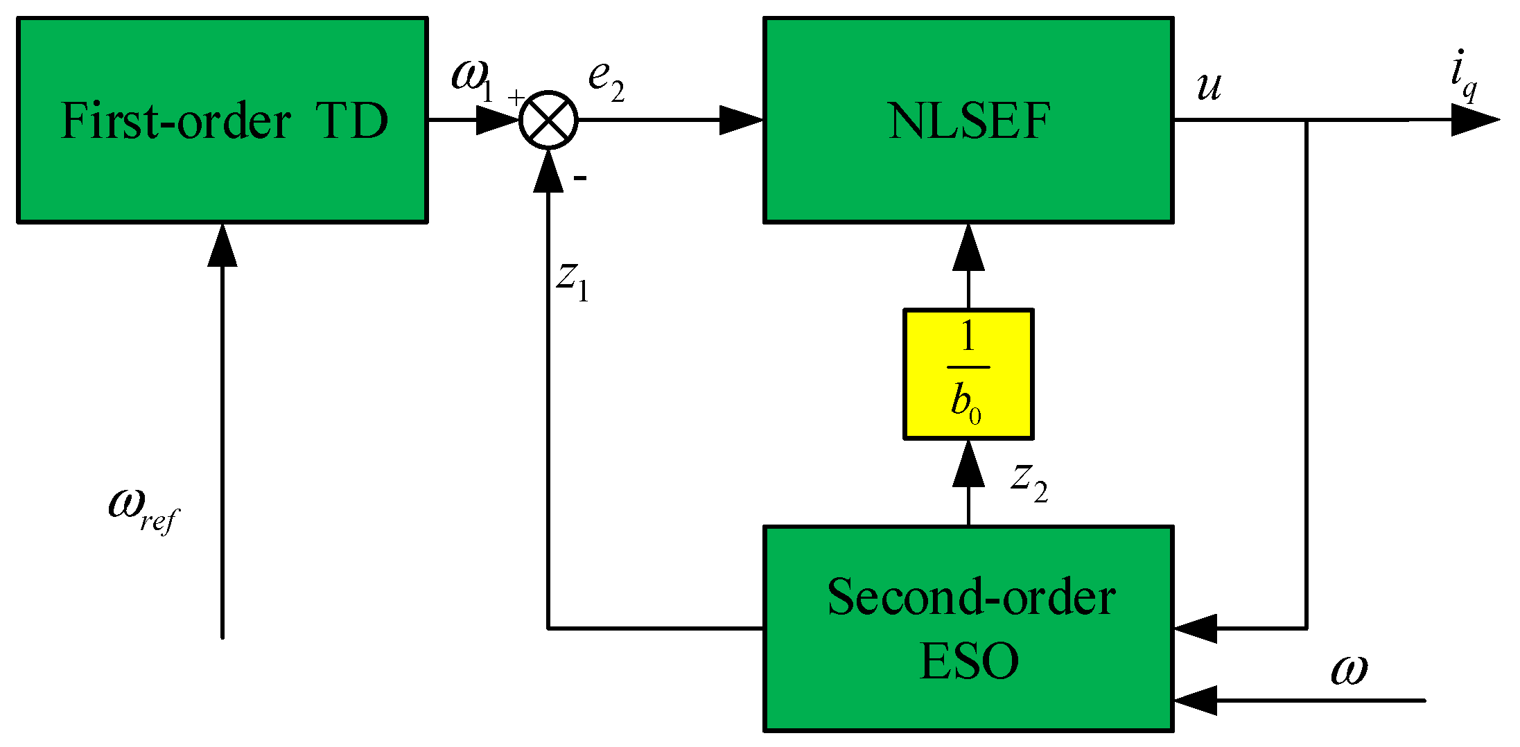
is the total disturbance term. A first-order ADRC of a PMSM is primarily composed of a first-order TD and a second-order ESO and NLSEF. The input of the first-order ADRC is the target speed (
) and the feedback speed (
), and the output is
iq.
Figure 1 shows the first-order ADRC of a speed control loop.
3.1. Improved Nonlinear Function Design
The nonlinear function significantly influences the control performance of ADRC. The common nonlinear function in an ESO and NLSEF is
where
e is the deviation,
α is the nonlinear factor, and
δ is the filtering factor. In the characteristic curve of the
fal(∙) function, an obvious inflection point exists and the smoothness is poor. The inflection point will reduce the disturbance rejection ability and robustness of ADRC [
34].
To keep the characteristics, eliminate the inflection point, and improve the smoothness of the
fal(∙) function, a new function is proposed as
and
In Equation (7),
α is the nonlinear factor. Both
fal(∙) and
newfal(∙) functions are symmetric about the origin.
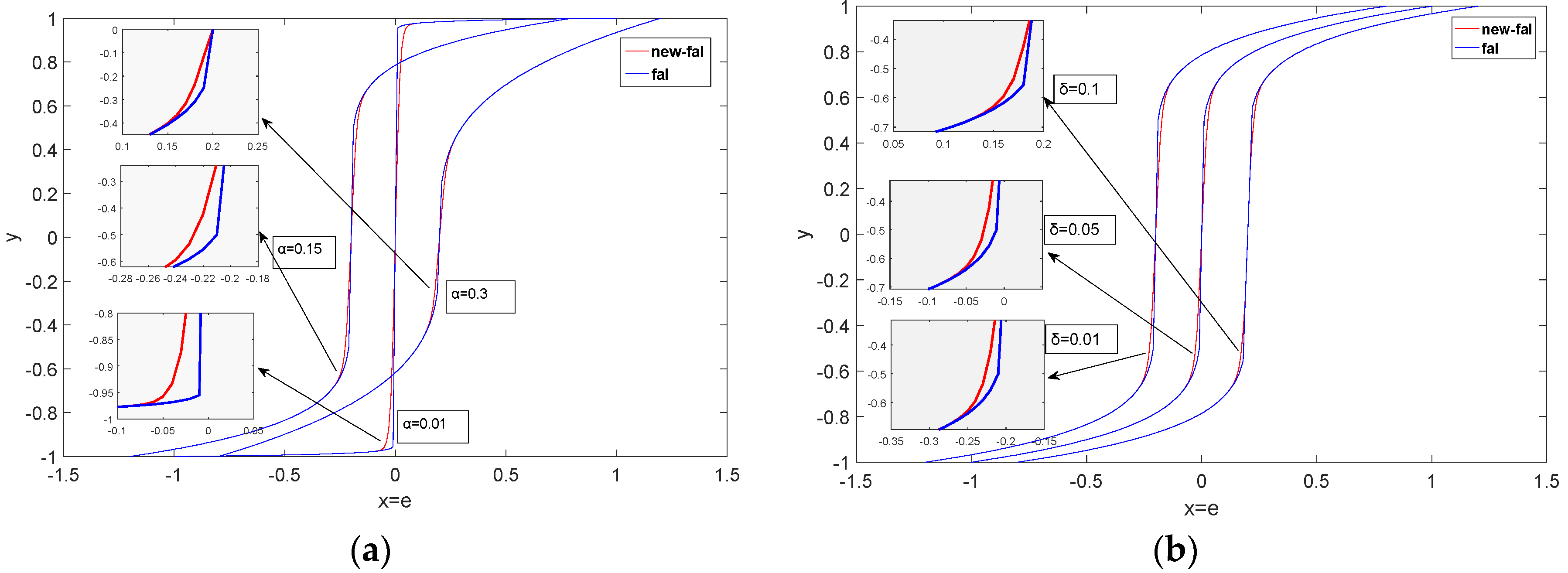
Figure 2 shows the characteristic curves of the
fal(∙) and
newfal(∙) functions with different parameters. For the convenience of observation, two groups of the curves of
fal(∙) and
newfal(∙) are shifted to the left and right from the origin by 0.2 respectively.
From the locally magnified figure in
Figure 2, an obvious inflection point close to the origin of the
fal(∙) can be observed, whereas the transition of the
newfal(∙) curve is smooth. In this study, a first-order ADRC is designed based on the
newfal(∙).
3.2. Improved TD Design and Stability Analysis
In reference [
35], the improved
fal(∙) function is used to improve the disturbance rejection ability of a quadrotor aircraft. The TD constructed using the
newfal(∙) function is listed below:
where
is the target speed,
is the output of the TD, which provides the fastest tracking of
, and
K is an adjustable parameter (
K > 0), which primarily affects the tracking speed of ADRC. The larger the
K value, the faster the TD tracking speed and the shorter the transition time.
The Lyapunov function of the TD is selected as
and the derivation of
can then be obtained from Equation (9) to obtain
The differential of
is
According to the characteristics of the newfal(∙), it has the same sign as e. When e > 0 or e < 0, < 0 is satisfied. When e = 0, = 0, according to the Lyapunov stability principle, > 0, the reciprocal of satisfies < 0, and the stability point is asymptotically stable. Therefore, the first order TD is asymptotically stable.
3.3. Improved Second Order ESO Design and Stability Analysis
The improved ESO is the core of the first-order ADRC in the PMSM speed control loop. It estimates the internal and external disturbances as total disturbance for compensation. From
Figure 1 and Equation (5), the improved second-order ESO expression of the PMSM speed loop is designed as
where
and
are the gains of the observer,
is the measured speed,
is the torque current,
is the estimator of
, and
is the total disturbance of the system.
Equation (13) can realise
and
. Let
ε1 =
z1 −
y and
ε2 =
z2 −
x. Subtract Equation (5) from Equation (13), the error state equation of the system can be obtained as
To prove the convergence of the system described by Equation (13),
is set to a constant value
. Let
ε21 =
ε1 and
ε22 =
1, then Equation (14) can be transformed into
Let the Lyapunov function of Equation (15) be
then there is at least one point
, satisfying
As
and
have the same sign and a > 0,
and
are both positive and negative. Their product is greater than or equal to 0. For
β02 > 0, it can be derived
The derivative of Equation (17) is
As is a monotonically increasing function, its derivative is greater than zero, and it is a bounded real number in the limited error range.
Let
F =
> 0. Equation (19) is then simplified as
If , then is satisfied. If , then < 0. If , then . If , then < 0. If = 0, then = 0. According to the Lyapunov stability theory, the improved ESO is asymptotically stable. Both and primarily affect the system accuracy and disturbance rejection ability. The experimental results show that increasing and in a certain range can reduce the steady-state error of the system and improve the disturbance rejection ability.
3.4. Stability Analysis of I-ADRC
The NLSEF, designed according to the block diagram in
Figure 1, is
where
are the control quantities. Let
. Substituting
into Equation (4), it reaches
The ESO convergence can guarantee that
. The tracking property of the TD can guarantee that
. According to
in Equation (21) and
in Equation (22),
can be obtained. As
is a constant, its differential is zero. As
and
,
can be obtained. Then, substituting
into Equation (22), it can be rewritten as
The Lyapunov function of Equation (23) is selected as
The derivate of Equation (24) is
As and have the same sign, If then = 0, Therefore, Equation (23) is asymptotically stable.
4. Simulation and Experimental Results Analysis
To confirm the performance of the I-ADRC under the vector control strategy, the PI controller of the speed loop is changed to ADRC and I-ADRC controllers. The PI controller is still used in the current loop and the other structures remain unchanged.
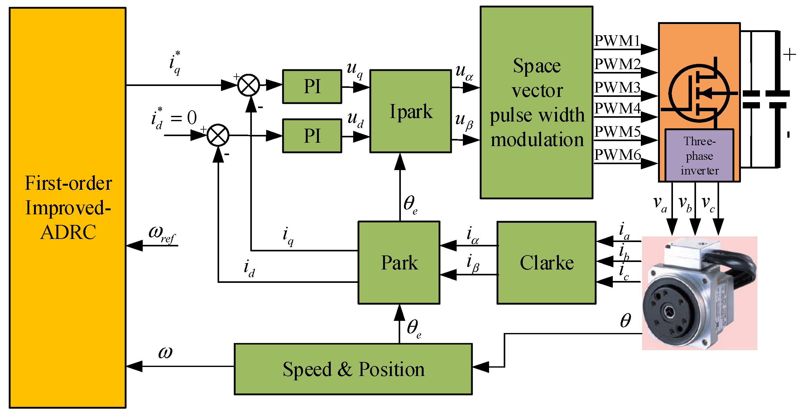
Figure 3 shows the structure block diagram of the PMSM vector control speed regulation system based on I-ADRC.
In field-oriented control (FOC), the three-phase current of the PMSM is transformed into iq and id by the Clarke and Park transformation. Both the torque and speed of the PMSM can be controlled by controlling the torque current iq. When id = 0, the flux is completely supplied by the permanent magnet and all the current of the motor is used to generate the electromagnetic torque.
4.1. Analysis of Simulation Results
To verify the effectiveness of the I-ADRC, a simulation wass conducted in MATLAB/Simulink. The PI control parameters were obtained by the trial-and-error method. Kp affects the response speed and overshoot of the system and Ki affects the stability accuracy of the system. Kp was adjusted from small to large until oscillation occurred, Ki was adjusted from large to low, and the steady state accuracy of the system was guaranteed. The final PI control parameters were Kp = 0.7 and Ki = 0.012. The control parameters of the ADRC were adjusted such that the time reaching the target speed and the steady state error were the same. To confirm the performance under the same condition, ADRC and I-ADRC adopted the same set of control parameters. Moreover, the I-ADRC had only one additional gain in the newfal(∙) function. The target speed was set to 1000 rpm, and a 5 N·m load was suddenly applied at 0.05 s and unloaded at 0.1 s. The control performance of the three algorithms was compared based on the simulation results.
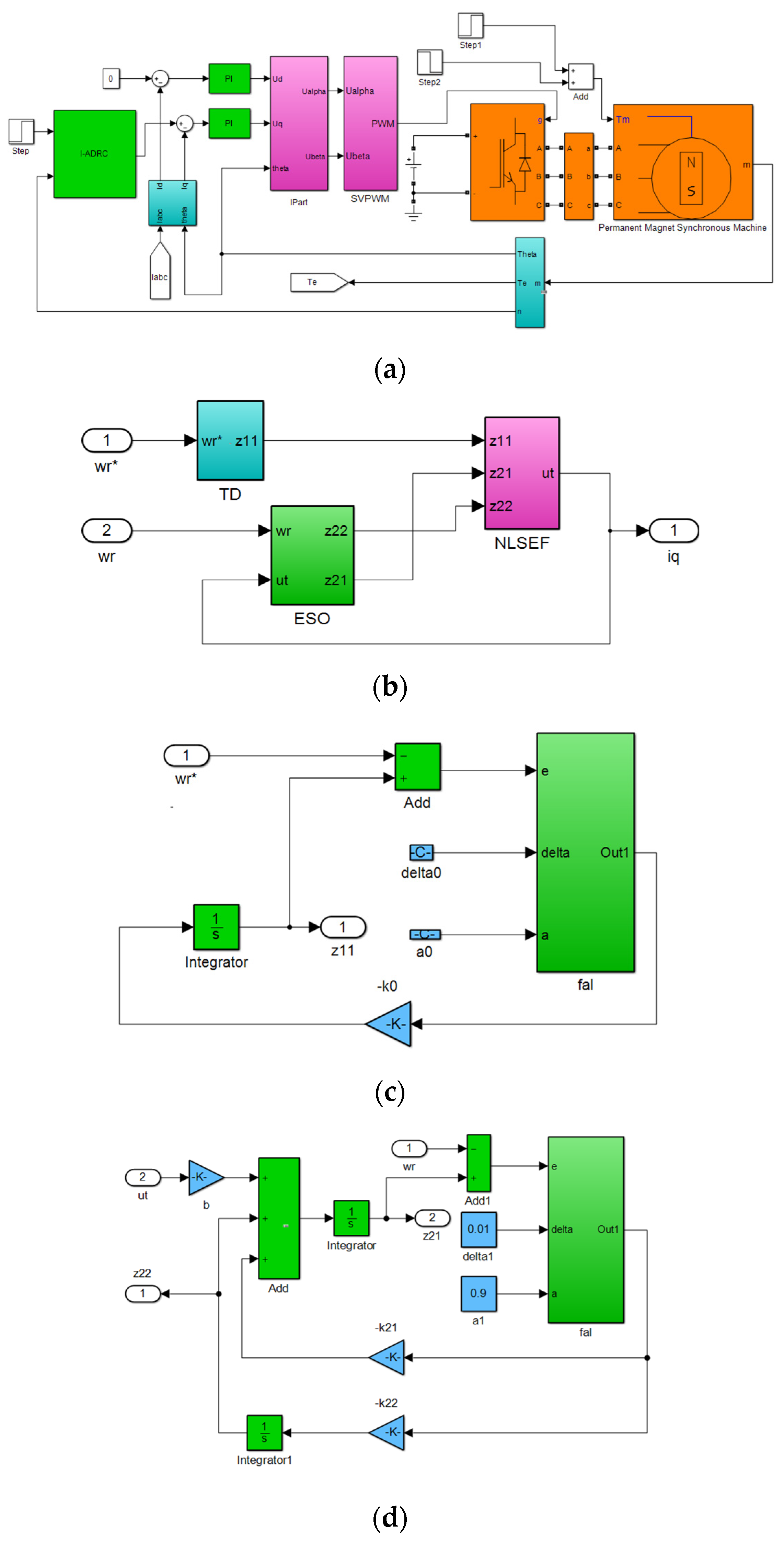
The simulation model is shown in
Figure 4. I-ADRC is adopted in the speed control loop, and the PI controller is used in the current control loop.
4.1.1. Speed Simulation Results Analysis
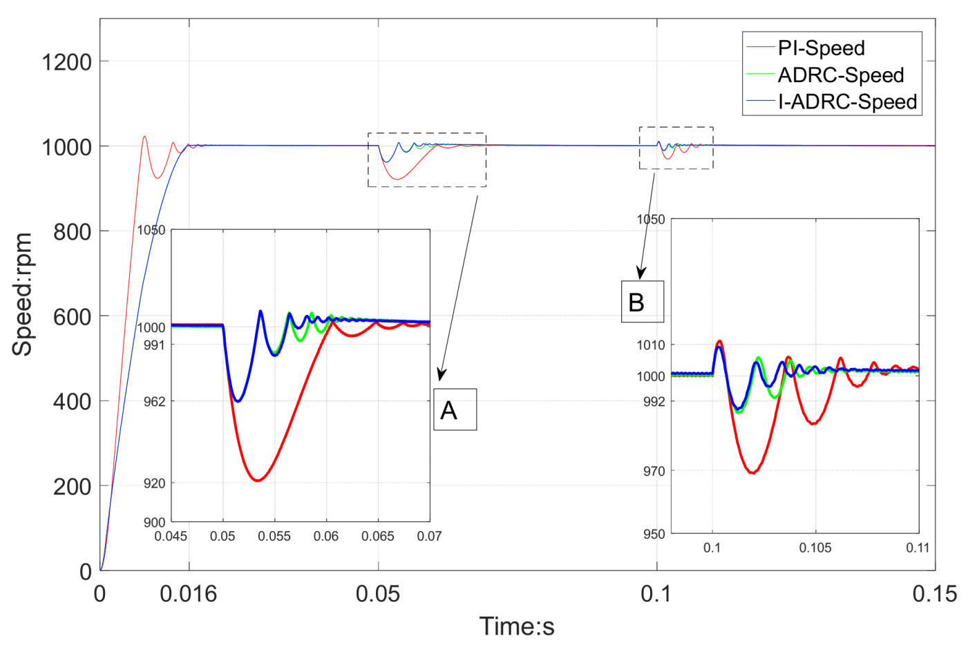
From the speed simulation results in
Figure 5, it can be observed that the three control algorithms stabilise at 0.16 s. However, the PI control algorithm has oscillation and overshoot. When a 5 N·m load is suddenly loaded at 0.05 s, the minimum speed of the PI control algorithm is 920 rpm, whereas the minimum speed of ADRC is 962 rpm. ADRC and I-ADRC are restored to a steady state after 0.06 s and the PI is restored to a steady state after 0.07 s.
When the load is suddenly released at 0.1 s in the partial enlarged region B in
Figure 5, it can be observed that the maximum output speed of the three control algorithms is 1010 rpm. However, the minimum speed of the PI controller is 970 rpm and the minimum speed of ADRC and I-ADRC is 990 rpm. Moreover, ADRC velocity is 992 rpm and the I-ADRC velocity is 994 rpm in the second velocity sag.
The simulation results demonstrate that disturbance rejection ability of I-ADRC is better than that of the PI and ADRC.
4.1.2. Analysis of Three Phase Current Simulation Results
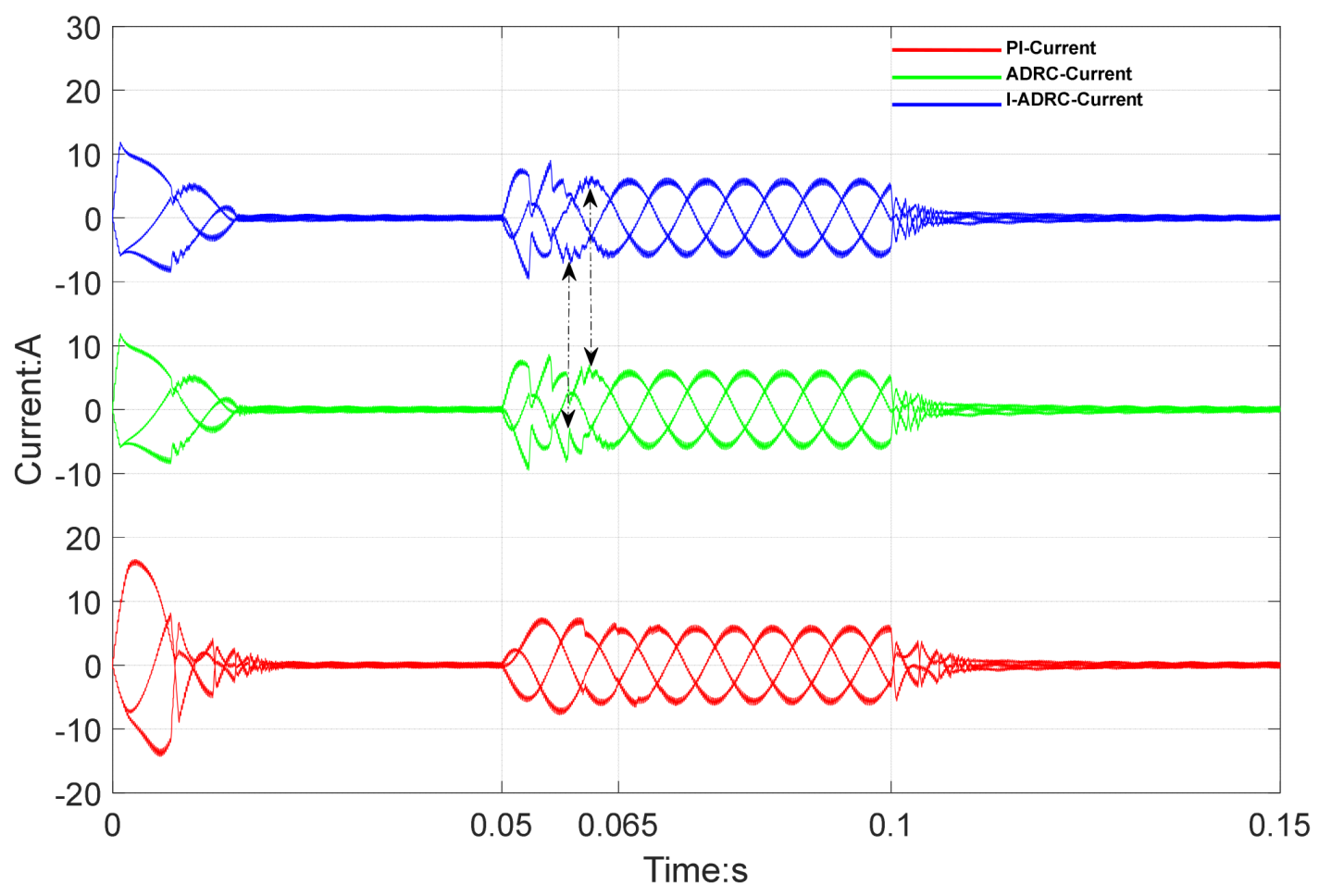
From the current simulation results in
Figure 6, the current fluctuation amplitude of the PI control algorithm at start-up time is significantly higher than that of ADRC and I-ADRC. When a load is applied at 0.05 s, the amplitude of the three-phase current changes. At 0.065 and 0.066 s, the current waveforms of ADRC and I-ADRC are stable; however, that of the PI controller is still in transition state. When comparing ADRC and I-ADRC, the I-ADRC current waveform reaches steady state; the ADRC current waveform is still in transition state. This phenomenon is consistent with the third and fourth sag of ADRC velocity in the partially enlarged figure of velocity simulation results in
Figure 5. When unloading at 0.1 s, the difference in current between the three control algorithms is not obvious.
4.1.3. Analysis of Torque Simulation Results
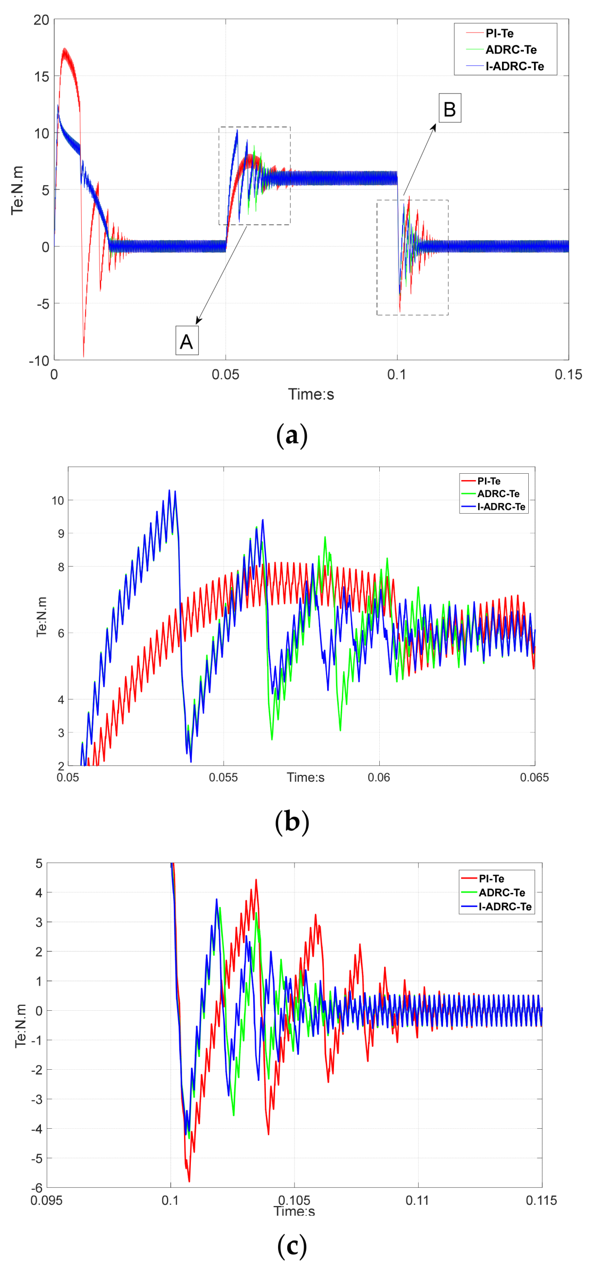
Figure 7 shows the torque simulation results.
Figure 7a shows the torque curve of the entire process.
Figure 7b,c show the partially enlarged regions A and B referred to in
Figure 7a. From
Figure 7a, the oscillation amplitude and time of the PI torque curve are significantly larger than those of ADRC and I-ADRC during the initial starting stage. When a 5 N·m load is applied at 0.05 s, the torque amplitude of the PI controller is 8 N·m, whereas the torque amplitude of ADRC and I-ADRC is 10 N·m. The recovery time of ADRC and I-ADRC is less than that of the PI controller.
The torque fluctuation of the PI controller in
Figure 7b is greater than that of ADRC and I-ADRC. Both the maximum and minimum of the third torque ripple of I-ADRC and ADRC are 2.4 and −2.9 N·m and 3.2 and 3.6 N·m, respectively. This changing trend is consistent with that of ADRC and I-ADRC velocity in the partially enlarged A and B regions of
Figure 4. When unloading at 0.1 s, the convergence time of the torque curve of the PI control algorithm is longer than that of ADRC and I-ADRC. From the partially enlarged
Figure 7b, the torque fluctuation amplitude of the ADRC is greater than that of I-ADRC, between 0.1025 s and 0.105 s.
4.2. Analysis of Experimental Results
In this study, experimental verification is conducted using a LINKS RS PMSM servo platform. The details of the experimental platform can be inquired from Beijing Lingsi Chuangqi Technology Co., Ltd. The Links RS PMSM control system primarily comprises the primary control software (RT SIM Plus), IO module library (RT LIB), real time code generator (RT Coder), and real time simulation engine (RT Engine).
Figure 8 shows the servo control platform and load system.
Table 1 shows the parameters of the PMSM used in the experiment. The control parameters of ADRC and I-ADRC are the same (
Table 2). The motor speed is obtained by an encoder. The measurement speed is processed by a first-order low pass filter. The execution frequency of the current loop, speed loop, and the frequency of recorded data were set to 10 kHz, 1 kHz, and 1 kHz, respectively. No load and on load tests were conducted for the three algorithms.
4.2.1. No Load Speed Regulation Result Analysis
The PI control parameters were adjusted to be consistent with the steady state times and errors of ADRC and I-ADRC.
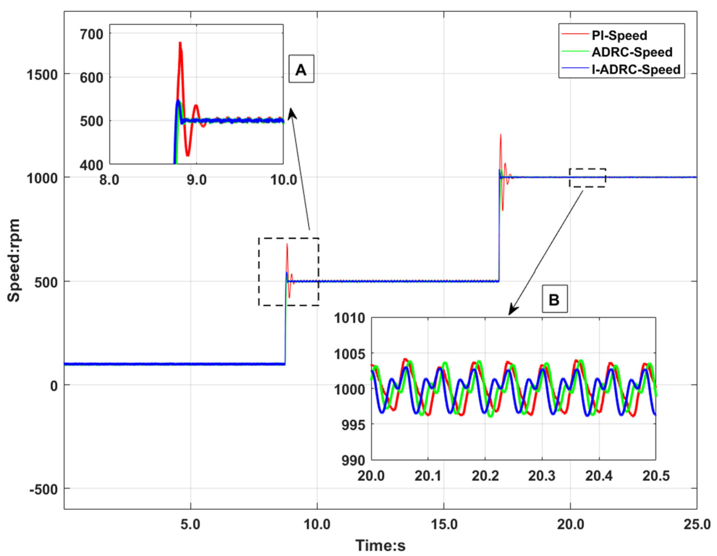
Figure 9 shows the no load speed response curve, and the step speed is set to 100 rpm, 500 rpm, and 1000 rpm, for the PI, ADRC, and I-ADRC, respectively. From the partially magnified region A in
Figure 9, ADRC and I-ADRC reach the steady state at 8.85 s and the PI reaches the steady state at 9.09 s. The overshoot of the PI control algorithm is larger than ADRC and I-ADRC. From the locally enlarged region B in
Figure 9, the velocity fluctuation of ADRC and the PI ranges from −5–+5 rpm and the velocity fluctuation of I-ADRC ranges from −4–+4 rpm.
4.2.2. Analysis of Load Speed Test Results
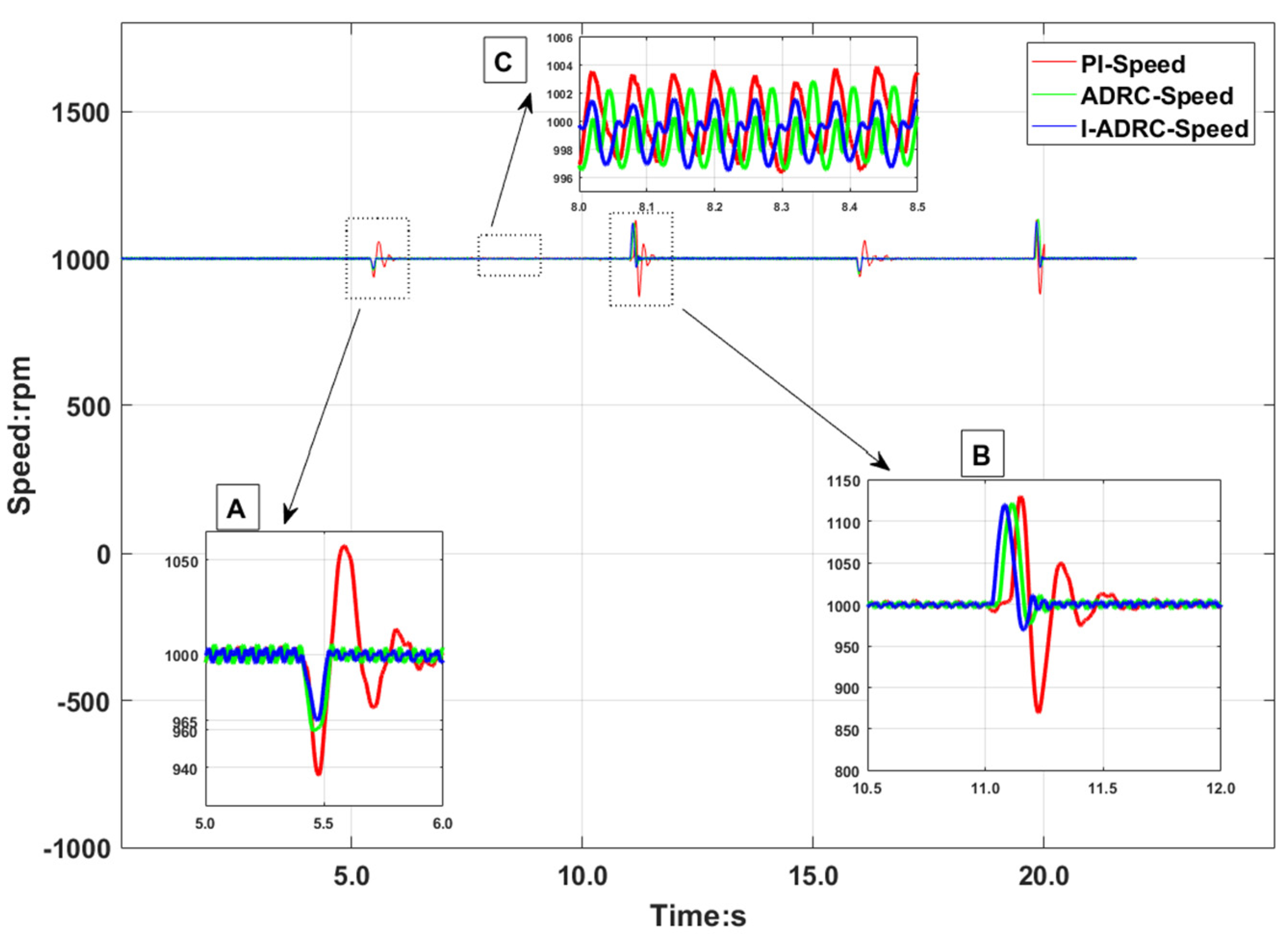
The rated load of the motor is 0.318 N·m. During the experiment, the load is set to 0.15 N·m by a magnetic powder brake. The PMSM speed was set to 1000 rpm, a 0.15 N·m load was applied at 5.4 s and unloaded at 11 s, and a 0.15 N·m load was applied at 16 s and unloaded at 19.8 s. The disturbance rejection ability of different algorithms is evaluated by repeatedly loading and unloading.
Figure 10 shows the test results.
Partially magnified views A and B in
Figure 10 indicate loading and unloading, respectively. In A, the minimum speed 940 rpm for the PI control, 960 rpm for the ADRC, and 965 rpm for the I-ADRC control. The speed disturbance rejection ability of the I-ADRC control strategy is better than that of the ADRC and the PI.
From the locally magnified region B, the maximum speed fluctuation of the three control algorithms is 1100 rpm; however, the minimum speed of the PI control algorithm is about 872 rpm and the minimum speed of the ADRC and I-ADRC control algorithms is about 970 rpm.
The locally magnified region C in
Figure 10 indicates the steady state velocity, in which the velocity fluctuation of the PI is −4–4 rpm, velocity fluctuation of ADRC is −4–3 rpm, whereas the velocity fluctuation of I-ADRC is −3–2 rpm; therefore, the steady state error is smaller.
4.2.3. Analysis of 3 Phase Current Test Results
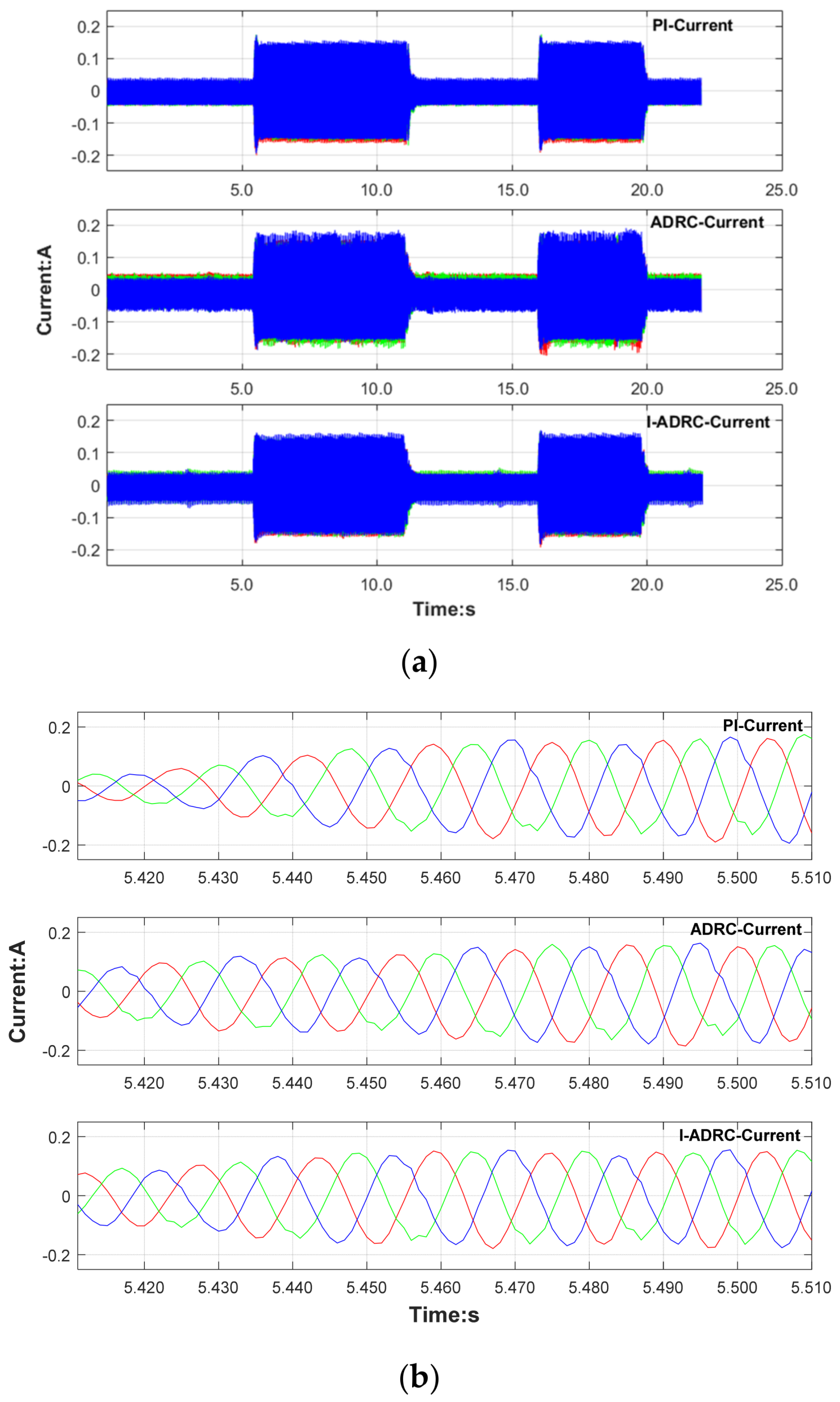
Figure 11 shows the current variation curve during loading and unloading.
Figure 11a shows the complete current curve of the three control algorithms and
Figure 11b is the partial amplification of the loading part in
Figure 11a. From
Figure 11b, between 5.40 and 5.46 s, I-ADRC has the largest current amplitude, followed by ADRC, and the PI has the smallest current amplitude. The larger the current, the larger the rotor output torque. The measured current data show that the disturbance ability of I-ADRC is better than that of ADRC and the PI. This current change is consistent with the velocity change curve in the locally enlarged B region in
Figure 10.
5. Conclusions
To improve the disturbance rejection ability of the PMSM speed-control loop, a new nonlinear function with improved smoothness is proposed. Based on the nonlinear function, an improved first-order ADRC is designed. The Lyapunov stability of the first-order TD and the second-order ESO of the I-ADRC are analysed, and the asymptotic stability of the improved first-order ADRC control system is theoretically confirmed. To verify the speed loop control performance of I-ADRC, the PI, ADRC, and I-ADRC control strategies are realised both in simulation and experiments. Based on the simulation and experimental results, the characteristics of speed, current, and torque in the process under loading and unloading conditions are analysed. The results show that the PMSM speed control based on I-ADRC has better stability than the other two methods. I-ADRC has stronger disturbance rejection ability and robustness than the PMSM speed control based on the PI and ADRC.
