Fatigue Analysis of Actuators with Teflon Impregnated Coating—Challenges in Numerical Simulation
Abstract
1. Introduction
2. Criteria for Fatigue Damage Failure
2.1. Strain–Life
2.2. Linear Elastic Fracture Mechanics (LEFM)
2.3. Stress–Life
2.4. Selection of Fatigue Analysis Methods
3. Fatigues by Wears and Coatings
3.1. Aluminum Alloys as Substrates
3.2. Polytetrafluoroethylene (PTFE) as Coatings
3.3. Coating over Aluminum Alloys
- ▪
- Types and processes of surface treatments: Murakami [59] adopted the ultrasonic nanocrystal surface modification (UNSM) technology for the surface treatment of aluminum alloys. This UNSM technology increased fatigue strength by 50%, surface hardness by 40%, and reduced the surface roughness by a significant amount. Ziemian et al. [54] discussed the effects of the coating process on crack initiation subject to cyclic loading on Al2024 alloy. The results showed that the deposition of cold-sprayed coating could improve the fatigue strengths in contrast to other coating methods. Similarly, Puchi-Cabrera et al. [53,60] conducted the fatigue experiments on 7075-T6 aluminum alloy coated with WC-12Co or WC-10Co-4Cr by high velocity oxygen fuel spray. The coatings by spray led to a significant increase in fatigue strength of the substrate. Its potential was in replacing electrolytic hard chromium plating in aircraft applications. Baragetti and Terranova [61] investigated various process parameters in PVD on residual stresses and fatigue life of steel and aluminum alloys. Baragetti et al. [62] compared the fatigue performance of different coating materials including DLC, SiOx, and WC/C by CVD or PVD processes. Only WC/C was found to improve the fatigue life while the rest of the coating methods reduced the fatigue life. Genel [63] looked into the fatigue life under corrosion. Experiments were conducted to compare the fatigue behavior of bare and anodic oxide coated 7075-T6 alloy in air and 3.5%NaCI solution. The presence of corrosive attack reduced fatigue performance of the alloy drastically. Examinations on the surfaces of the corrosion-fatigued specimens revealed that cyclic loading stimulated corrosion pitting. Wu et al. [64] performed an FEA analysis to investigate the impact of coating thickness on stress distribution for steel substrate with multilayer ceramic coatings (hot dipping aluminum and plasma electrolytic oxidation) subject to normal pressure load. They found that the surface tensile stress was mainly affected by the thickness ratio of the aluminum layer when the total thickness of the coating was kept constant.
- ▪
- Imperfection in substrates and interfaces: Although the exact cause of fatigue degradation of coated aluminum alloy has not been clearly understood, it is generally agreed that stress concentration at micro-imperfections (micro-cracks) should be the main factor. Under fluctuating loads, the base metal at those defects loses its plasticity, which leads to the propagation of local cracks and reduces the effective area until the applied stress exceeds the yield strength and causes failure [56]. Nanninga [19] indicated that four main factors affecting the fatigue life of extruded aluminum were extrusion microstructure (grain size, aspect ratio, precipitate structure and texture), seam welds, charge welds, and die lines. Person [65] specifically investigated the fatigue life of aluminum alloy weld, and he proved that joint geometry had the greatest effect on fatigue strength. Ambriz et al. [66] conducted tests and concluded that the process of fusion welding on 6061-T6 led to a significant loss of mechanical strength and the fatigue strength defined by the crack growth on the substrates. Wasekar et al. [67] evaluated the influence of microarc oxidation (MAO) coatings on the fatigue life of 6061-T6 aluminum alloy in the rotating bending test. They found that the high-cycle fatigue life was significantly degraded due to the presence of MAO coatings, particularly when a low magnitude of stress and thicker coatings were used, while the surface roughness did not have a noticeable impact on the fatigue life. Alzoubi et al. [68] investigated the effects of coating thickness, materials, part geometry, temperature, and humidity on the fatigue life of thin-film metal coated flexible substrates, polyethylene terephthalate (PET), and polyethylene naphthalate (PEN) under high cycle bending loads. Ochi et al. [30] Yamamoto et al. [31] and investigated the impact of weld joints on the fatigue life of aluminum alloys.
- ▪
- Residual stresses from coating process: Residual stresses induced by coating affect the fatigue life. Asquith et al. [69] indicated that the fatigue failure in hard oxide-coated aluminum was mitigated by interfacial compressive stresses while combining cold work with hard oxide coatings could improve fatigue performance. Under a thin film, thermal stresses were determined by the difference of thermal expansions of film and substrate. If a film was initially at a stress-free temperature T_0 and used at a different temperature T, the biaxial strain mismatch with respect to the substrate was evaluated as [70], where and are the coefficients of thermal expansion of the film and substrate, respectively. This was supported by the work from Oskouei and Ibrahim [71]. Residual stresses in the surface coating affected material properties such as fatigue life, dimensional stability, and corrosion resistance. Shen et al. [72] proposed the use of micro-oxidation ceramic coatings for 6061 aluminum alloy to reduce the residual stresses induced during the coating process. They showed that the residual stress in the ceramic coatings was compressive in nature, and it increased at the beginning and then decreased with micro-arc oxidation. Sadeler et al. [73,74] investigated the impact of hard anodizing on the fretting fatigue behavior of a 2014-T6 aluminum alloy and found that the hardness was significantly improved up to about 380 (HV) from 175 after hard anodizing coating. Their results also indicated that fatigue life in a high stress region was shorter than that of the other material conditions, whereas the fatigue life in a low stress region was longer than that of the materials (T6 heat treated). Microscopic examination showed that fatigue fracture was initiated in the coating at high-stress regions, whereas fatigue fracture initiation started on the interface between the coating and substrate in low stress regions. Mindivan [75] tried WC-1Co+6% ethylene (ETFE) coating on AA2024-T6 aluminum alloy with the process of plasma spray and high velocity oxygen fuel (HVOF); it was found that the HVOF substrate exhibited higher hardness, greater contact angles, better tribological performance, and a higher amount of retained WC when compared to the plasma sprayed WC-10Co+6% ETFE coating.
- ▪
- Tribological behavior of coatings at interface: The fatigue life of a coated aluminum alloy is also closely related to the tribological behavior at the contact interface. The research monograph [76] investigated the effect of surface coating on wear. In particular, the chapter by Ramalingam and Zheng [77] presented an analytic model on the stress distribution caused by the elastic difference of coating and substrates. Sheng [78] developed experimental techniques to assess the quality of thin polymer films, including friction, durability, and interfacial adhesion. The characteristics of friction and durability of PTFE films on aluminum substrate were investigated using ball-on-disk and ball-on-plate configurations. The effects of normal forces, sliding speed, and surface roughness on the friction coefficient were quantitatively examined by the variance. The results indicated that the native surface roughness of the substrate had the most significant effect on the coefficient of friction and durability, and accordingly, surface roughness of 0.5 m had the best durability of PTFE thin film.
- ▪
- Operating temperature: Material strengths, including fatigue strength, vary with temperature. Bahaideen et al. [79] observed that the fatigue life of 2024-T4 aluminum alloy was reduced by a factor of 1.2 to 1.4 at an elevated temperature in comparison with that at room temperature. Brammer [80] used the traditional strain–life relation to characterize the fatigue behaviors of 6061-T6 and 7075-T651 aluminum alloys. The study found that the impact of heat exposure to low cycle fatigue was negligible; however, the high cycle fatigue was decreased significantly due to heat, and cracks were initialized as intermetallic particles in the peak-aged alloys and debonded particles. Oskouei and Ibrahim [71] studied Al 7075-T6 coated with 3 μm thick titanium nitride (TiN) and found the deposition process operated at a higher temperature reduced the tensile properties of the coating-substrate system.
3.4. Contact Stresses and Fatigue Damage at Interfaces
4. Finite Element Modeling for Fatigue Analysis
4.1. FEA-based Fatigue Analysis
4.2. Fatigue Analysis in Product Designs
4.3. FEA Software Packages for Fatigue Analysis
5. Challenges in Virtual Fatigue Analysis
5.1. Modeling of Thin Coating
5.2. Fatigue Properties of Coating
5.3. Fluctuating Loads and Boundary Conditions
- ▪
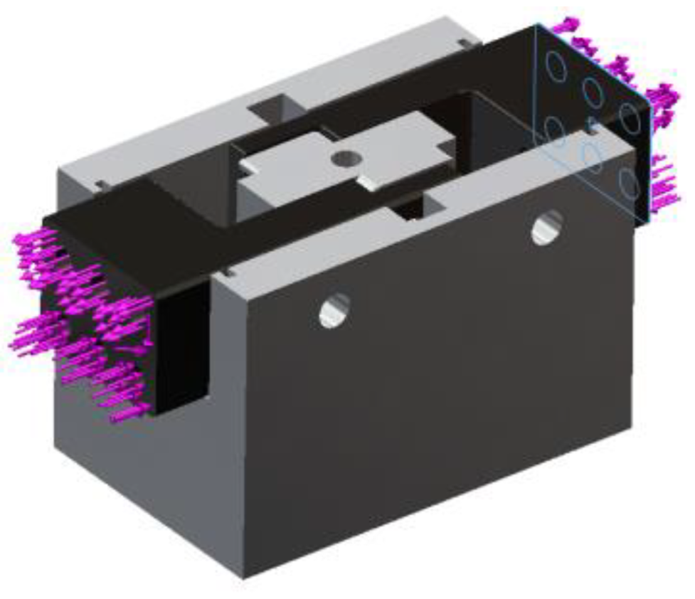
- Whether a pressure or force load should be applied?
- ▪
- How to apply a moment load adequately?
- ▪
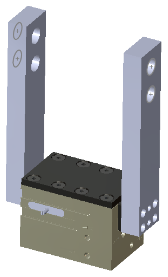
- How to define contact and component sets for the assembled gripper appropriately?
- ▪
- How to model the friction at contact interfaces?
- ▪
- What set of surfaces should be constrained and in what form?
- ▪
- What is an appropriate ratio of the mean and alternating loads in the characterization of loads?
- ▪
- Is it necessary to take into account the non-linearity of material properties?
5.4. Robustness of Solving Process
5.5. Verification and Validation
6. Procedure for Systematic Virtual Fatigue Analysis
6.1. Simplify Assembly Models
6.2. Define Material Properties of Coated Parts
6.3. Contacts with Motion
6.4. Constraint Types at Contact Surfaces
6.5. External Loads
6.6. Meshing of Part Geometries
6.7. Solving FEA Models
6.8. Fatigue Analysis Model
6.9. Assess Fatigue Life
7. Summary
- (1).
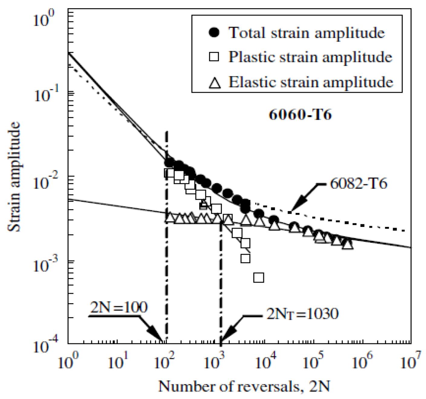
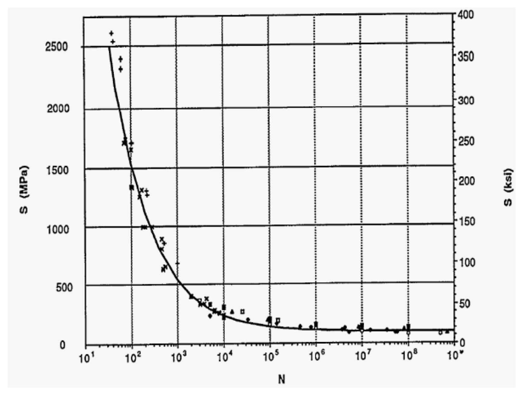
- There are three methods to predict fatigue life of machine parts, i.e., strain–life method, linear elastic fracture method (LEFM), and stress–life method. The stress–life method is most commonly used, in particular, for high-cycle applications and applications beyond the endurance limit. The other two methods require simulating the accumulation of cracks or stains, which is not practical in fatigue analysis of actuators.
- (2).
- Teflon Impregnated and hard coated surfaces have been widely used to improve the wear and corrosion resistance of aluminum alloys. However, it is found that hard coated surfaces adversely affect the fatigue life of substrates. Efforts have been made on the processes and methods to alleviate this effect, but a general solution to eliminate this effect is not available.
- (3).
- Many FEA tools, such as Ansys, Abaqus, SolidWorks, FEMLab, Deform3D, Nastran, COMSOL, and some other sophisticated FEA codes, have capabilities for fatigue analysis of coated parts. However, most FEA models are limited to two-dimensional applications and they are mainly for verification purposes under testing conditions. Few three-dimensional FEA models are currently available for the fatigue life analysis of hard coated parts. Detailed modeling of assembled parts with thin coatings poses challenges to any FEA package because an FE model would require a prohibitively large number of elements for a convergent solution.
- (4).
- In comparison to traditional engineering materials, the knowledge of material properties of hard-coated aluminum alloys is very limited. Due to the importance of material properties in numerical simulations, experiments are required to characterize the material properties of the hard coat itself and the bonding mechanism of the hard coat and substrate interface. Note that the variables and parameters in anodizing processes could affect the material properties of the hard coated aluminum alloy, and thus it is important to maintain consistency in material properties in design/analysis, prototyping, testing, and verification.
- (5).
- Developing a design process to predict the fatigue life of a hard coated part is feasible. The activities involved in the design process include: (a) preparation of a CAD model, (b) defining, revising, and expanding custom material library, (c) defining fatigue properties such as S-N curves, (d) building and running an FEA model for static analysis, (e) extending the static analysis model to fatigue analysis, and (f) supporting the parametric design for new product development. During the design process, manual intervention and arbitration should be minimized.
Author Contributions
Funding
Institutional Review Board Statement
Informed Consent Statement
Data Availability Statement
Conflicts of Interest
References
- Bi, Z.M.; Wang, X.Q. Computer Aided Design and Manufacturing; Wiley: Hoboken, NJ, USA, 2020; ISBN 978-1-119-53424-2. [Google Scholar]
- Bi, Z.M.; Meruva, K. Modeling and predication of fatigue life of robotic components in intelligent manufacturing. J. Intell. Manuf. 2019, 30, 2575–2585. [Google Scholar] [CrossRef]
- Liu, C.; Bi, Z.M.; Ran, J.; Gu, J.; Wang, X.; Zhang, C. Modeling and Verification of Fatigue Damage for Compliant Mechanisms. Robotica 2019, 37, 1–17. [Google Scholar] [CrossRef]
- Bi, Z.M.; Mueller, D. Finite element analysis for diagnosis of fatigue failure of composite materials in product development. Int. J. Adv. Manuf. Technol. 2016, 87, 2245–2257. [Google Scholar] [CrossRef]
- Bi, Z.M.; Mueller, D. Friction Predication on Pin-to-Plate Interface of PTFE Material and Steel. Friction 2019, 7, 268–281. [Google Scholar] [CrossRef]
- Nie, S.; Li, Y.; Shuai, G.; Tao, S.; Xi, F. Modelling and simulation for fatigue life analysis of robots with flexible joints under percussive impact forces. Robot. Comput. Integr. Manuf. 2016, 37, 293–301. [Google Scholar] [CrossRef]
- Xu, D.; Wei, Q.; Qu, S. Fatigue life analysis of the actuator based on co-simulation. In Proceedings of the 2015 First International Conference on Reliability Systems Engineering (ICRSE), Beijing, China, 21–23 October 2015. [Google Scholar] [CrossRef]
- Kingsley, D.A.; Quinn, R.D. Fatigue life and frequency response of braided pneumatic actuators. In Proceedings of the IEEE Robotics and Automation Conference, Washington, DC, USA, 11–15 May 2002. [Google Scholar]
- Woo, S.C.; Goo, N.S. Effect of electric cyclic loading on fatigue cracking of a bending piezoelectric hybrid composite actuator. Compos. Sci. Technol. 2009, 69, 1764–1771. [Google Scholar] [CrossRef]
- Zhang, W.J.; Luttervelt van, C.A. Towards a resilient manufacturing system. CIRP Ann. 2011, 60, 469–472. [Google Scholar] [CrossRef]
- Kang, J.J.; Xu, B.S.; Wang, H.D.; Wang, C.B. Investigation of a novel rolling contact fatigue/wear competitive life test machine faced to surface coating. Tribol. Int. 2013, 66, 249–258. [Google Scholar] [CrossRef]
- Seo, J.W.; Jun, H.K.; Kwon, S.J.; Lee, D.H. Rolling contact fatigue and wear of two different rail steels under rolling-sliding contact. Int. J. Fatigue 2016, 83, 184–194. [Google Scholar] [CrossRef]
- Lv, Z.Y.; Xiong, J.J.; Tong, L.; Zhu, Y.T. A practical approach for evaluating safe fatigue life of hydraulic actuator in helicopter based on a nominal force concept and minimal datasets. Aerosp. Sci. Technol. 2017, 62, 158–164. [Google Scholar] [CrossRef]
- Garcia, M.A.; Veloso, L.A.M.; de Castro, F.C.; Arujo, A.; Ferreira, J.L.A.; da Silva, C.R.M. Experimental device for fretting fatigue tests in 6201 aluminum alloy wires from overhead conductors. Wear 2020, 460-461, 203448. [Google Scholar] [CrossRef]
- Shabani, P.; Tageri-Begrooz, F.; Mousavi, S.S.S.; Shokrieh, M.M. Very high cycle and gigacycle fatigue of fiber-reinforced composites: A review on experimental approaches and fatigue damage mechanisms. Prog. Mater. Sci. 2021, in press. [Google Scholar] [CrossRef]
- Sunde, S.L.; Haugen, B.; Berto, F. Experimental and numerical fretting fatigue using a new test fixture. Int. J. Fatigue 2021, 143, 1006011. [Google Scholar] [CrossRef]
- Pilkey, W.D.; Pilkey, D.F.; Bi, Z.M. Peterson’s Stress Concentration Factors; 4th Version; Wiley: Hoboken, NJ, USA, 2020; ISBN1 978-119532514. ISBN2 119532515. [Google Scholar]
- Ramachandran, V.; Raghuram, A.C.; Krishnan, R.V.; Bhaumik, S.K. Failure Analysis of Engineering Structures: Methodology and Case Histories. 2005. Available online: http://nusretmeydanlik.trakya.edu.tr/MLZM%20MKN/Failure_Analysis_of_Engineering_Structures__Methodology_and_Case_Histories.pdf (accessed on 15 April 2021).
- Nanninga, N.E. High Cycle Fatigue of AA6082 and AA6063 Aluminum Extrusions. Ph.D. Thesis, Michigan Technological University, Houghton, MI, USA, 2008. Available online: http://digitalcommons.mtu.edu/etds/18 (accessed on 15 April 2021).
- Budynas, R.G.; Nisbett, J.K. Shigley’s Mechanical Engineering Design; 10th Version; McGraw-Hill Connect Engineering: New York, NY, USA, 2014; ISBN 978-0-07-339820-4. [Google Scholar]
- SAE. J1099, SAE Standards: Technical Report on Low Cycle Fatigue Properties Ferrous and Non-Ferrous of Materials. 2014. Available online: http://standards.sae.org/j1099_197502/ (accessed on 15 April 2021).
- Pommier, S. Basics Elements on Linear Elastic Fracture Mechanics and Crack Growth Modeling. Doctoral. France. 2017. Available online: https://hal.archives-ouvertes.fr/cel-01636731/document (accessed on 15 April 2021).
- NASA/FLAGRO. Fatigue User’s Guide>Crack Growth>NASA/FLAGRO. 2014. Available online: http://www.mscsoftware.com/training_videos/patran/Reverb_help/index.html#page/Fatigue%20Users%20Guide/fat_growth.08.8.html (accessed on 15 April 2021).
- Unigovski, Y.B.; Grinberg, A.; gerafi, E.; Gutman, E.M.; Moisa, S. Low-cycle fatigue of an aluminum alloy plated with multi-layer deposits. J. Optoelectron. Adv. Mater. 2013, 15, 863–868. [Google Scholar]
- Aparcio, C. What is Fatigue Analysis? 2013. Available online: http://simulatemore.mscsoftware.com/what-is-fatigue-analysis-msc-nastran/ (accessed on 15 April 2021).
- Balzers Oerlikon. Coated Components: Greater Performance and Reliability; Balzers Oerlikon: Balzers, Liechtenstein, 2010. [Google Scholar]
- Carroll, J.W. The Effects of Novel Surface Treatments on the Wear and Fatigue Properties of Steel and Chilled Cast Iron. Ph.D. Thesis, University of Michigan, Ann Arbor, MI, USA, 2012. [Google Scholar]
- Cobden, R.; Bandury, A. Aluminum: Physical Properties, Characteristics and Alloys. Available online: https://www.yumpu.com/en/document/read/3968974/aluminium-physical-properties-characteristics-core-materials (accessed on 15 April 2021).
- Borrego, L.P.; Abreu, L.M.; Costa, J.M.; Ferreira, J.M. Analysis of low cycle fatigue in AlMgSi aluminum alloys. Eng. Fail. Anal. 2004, 11, 715–725. [Google Scholar] [CrossRef]
- Ochi, H.; Sawai, T.; Yamanoto, Y.; Ogawa, K. Evaluation of tensile strength and fatigue strength of 6061 aluminum alloy friction welded joints by heat input and burn-off length. In Proceedings of the Twelfth International Offshore and Polar Engineering Conference, Kitakyushu, Japan, 26–31 May 2002. [Google Scholar]
- Yamamoto, Y.; Ochi, H.; Sawai, T.; Yamaguchi, H.; Ogawa, K. Fatigue strength of friction-welded 6061 aluminum alloy joints. Mater. Trans. 2007, 48, 2909–2913. [Google Scholar] [CrossRef]
- Alcoa. Alloy 6063: Understanding Extruded Aluminum Alloys. 2014. Available online: http://www2.galcit.caltech.edu/~tongc/html/data/elastic/Extruded_Alloy_6063.pdf (accessed on 15 April 2021).
- MatWeb. Aluminum 6063-T6. 2014. Available online: http://weilandslidingdoors.com/wp-content/uploads/2012/05/weiland-alu6063-properties.pdf (accessed on 15 April 2021).
- Yahr, G.T. Fatigue Design Curves for 6061-T6 Aluminum; CONF-930702-14; Oak Ridge National Laboratory: Oak Ridge, TN, USA, 1993. [Google Scholar]
- FEP Handbook. 2014. Available online: http://www.rjchase.com/fep_handbook.pdf (accessed on 15 April 2021).
- Dupont. An Introduction to DuPont Fluoropolymers, Part of DuPont Chemicals & Fluoroproducts. 2014. Available online: http://www2.dupont.com/GenX/en_US/assets/downloads/Dupont_Fluoropolymers_Introduction.pdf (accessed on 15 April 2021).
- Dupont. Teflon PTFE Properties Handbook. 2014. Available online: http://www.rjchase.com/ptfe_handbook.pdf (accessed on 15 April 2021).
- Mesbahi, A.H.; Semnani, D.; Khorasani, S.N. Performance prediction of a specific wear rate in epoxy nano-composites with various composition content of polytetrafluoroethylene (PTFE), graphite, short carbon fibers (CF) and nano-TiO2 using adaptive neuro-fuzzy inference system (ANFIS). Compos. Part B 2010, 43, 549–558. [Google Scholar] [CrossRef]
- Gong, R.; Wan, X.; Zhang, X. Tribological properties and failure analysis of PTFE composites used for seals in the transmission unit. J. Wuhan Univ. Technol. Mater. Sci. Ed. 2013, 28, 26–31. [Google Scholar] [CrossRef]
- Akdogan, G.; Stolarski, T.A.; Tobe, S. Wear of metal/PTFE coatings in rolling line contact. J. Mater. Sci. 2002, 37, 5013–5019. [Google Scholar] [CrossRef]
- Akdogan, G.; Stolarski, T.A.; Tobe, S. Wear performance of polytetrafluoroethylene-metal coatings in rolling/sliding line contact. Proc. Inst. Mech. Eng. Part J J. Eng. Tribol. 2003, 217, 103–114. [Google Scholar] [CrossRef]
- McCook, N.L.; Burris, D.L.; Kim, N.H.; Sawyer, W.G. Cumulative damage modeling of solid lubricant coatings that experience wear and interfacial fatigue. Wear 2007, 262, 1490–1495. [Google Scholar] [CrossRef]
- Gan, Y.X.; Aglan, H.; Fauhnan, P.; Bryan, C. Fatigue fracture mechanisms of particle and fiber filled PTFE composites. J. Reinf. Plast. Compos. 2001, 20, 766. [Google Scholar] [CrossRef]
- Aderikha, V.N.; Shapovalov, V.A. Effect of filler surface properties on structure, mechanical and tribological behavior of PTFE-carbon black composites. Wear 2010, 268, 1455–1464. [Google Scholar] [CrossRef]
- Teku. PTFE—Fluoroplastic Properties and Characteristic Data. 2014. Available online: http://teku-gmbh.de/pdf_en/EN_Fluoroplastics_s.pdf (accessed on 15 April 2021).
- Avanzini, A.; Donzella, G.; Gallina, D.; Pandini, S.; Petrogalli, C. Fatigue behavior and cyclic damage of peek short fiber reinforced composites. Compos. Part B Eng. 2013, 45, 397–406. [Google Scholar] [CrossRef]
- Frick, A.; Sich, D.; Heinrich, G.; Stern, C.; Gossi, M.; Tervoort, T.A. Relationship between structure and mechanical properties of melt processable PTFE: Influence of molecular weight and comonomer content. Macromol. Mater. Eng. 2013, 298, 954–966. [Google Scholar] [CrossRef]
- Teoh, S.H. Fatigue of biomaterials: A review. Int. J. Fatigue 2000, 22, 825–837. [Google Scholar] [CrossRef]
- Wang, Y.; Wang, H.; Yan, F. Investigation of transfer film of PTFE/bronze composites on 2024Al surface. Surf. Interface Anal. 2009, 41, 753–758. [Google Scholar] [CrossRef]
- Gillig, F.G. Study of Hard Coating for Aluminum Alloys; WADC Technical Report; Cornell Aeronautical Laboratory, Inc.: Wright-Patterson AFB, OH, USA, 1953; pp. 53–151. [Google Scholar]
- ASM International. ASM Handbook Corrosion, 9th ed.; ASM International: Materials Park, OH, USA, 1998; Volume 13. [Google Scholar]
- Shahzad, M.; Chaussumier, M.; Chieragatti, R.; Mabru, C.; Aria, F.R. Influence of surface treatments on fatigue life of Ai 7010 alloy. J. Mater. Process. Technol. 2010, 210, 1821–1826. [Google Scholar] [CrossRef]
- Puchi-Cabrera, E.S.; Staia, M.H.; Santana, Y.Y.; Mora-Zorrilla, E.J.; Lesage, J.; Chicot, D.; Barbera-Sosa, J.G.; La Ochoa-Perez, E.; Villalobos-Gutierrez, C.J. Fatigue behavior of AA7075-T6 aluminum alloy coated with a WC-10Co-4Cr cermet by HVOF thermal spray. Surf. Coat. Technol. 2013, 220, 122–130. [Google Scholar] [CrossRef]
- Ziemian, C.W.; Sharma, M.M.; Bouffard, B.D.; Nissley, T.; Eden, T.J. Effect of substrate surface roughening and cold spray coating on the fatigue life of AA2024 specimens. Mater. Des. 2014, 54, 212–221. [Google Scholar] [CrossRef]
- Wanstrand, P. Wear Resistant Low Friction Coatings for Machine Elements: Possibilities and Limitations. Ph.D. Thesis, ACTA Universitatis Upsaliensis, Uppsala, Sweden, 2000. [Google Scholar]
- Emeric, D.A.; Levine, S.; Washburn, K.L. The Effect of Surface Coatings on The Fatigue Strength of Aluminum Alloys; Report No. 2339; U.S. Army Mobility Equipment Research and Development Command: Fort Belvoir, VA, USA, 1981. [Google Scholar]
- Goetz, J.M. Investigation of Coating Cracking and Fatigue Strength of 7050-T74 Aluminum Alloy with Different Anodize Coating Thicknesses. Available online: https://kb.osu.edu/bitstream/handle/1811/327/Goetz_Thesis_SP05.pdf?sequence=1&isAllowed=y (accessed on 15 April 2021).
- Pineiro-Jimenz, A.; Villalobos-Gutierrez, C.; Staia, M.H.; Puchi-Cabrera, E.S. Tensile and fatigue properties of 6063-T6 aluminum alloy coated with electroless Ni-P deposit. Mater. Sci. Technol. 2007, 23, 253–260. [Google Scholar] [CrossRef]
- Murakami, R.-I. Fatigue Properties of Aluminum Alloy (A6061-T6) with Ultrasonic Nano-Crystal Surface Modification, Advanced Material Lab in Kyungpook National University. 2014. Available online: http://www.me.tokushima-u.ac.jp/zairyoukyoudo/M22/No4%20Fatigue%20properties.pdf (accessed on 15 April 2021).
- Puchi-Cabrera, E.S.; Maccio, R.; Staia, M.H. Fatigue behaviour of 7075-T6 aluminum alloy coated with WC-12Co alloy deposited by plasma spray. Surf. Eng. 2006, 22, 253–262. [Google Scholar] [CrossRef]
- Baragetti, S.; La Vecchia, G.M.; Terranova, A. Variables affecting the fatigue resistance of PVD-coated components. Int. J. Fatigue 2005, 27, 1541–1550. [Google Scholar] [CrossRef]
- Baragetti, S.; Lusvarghi, L.; Bolelli, G.; Tordini, F. Fatigue behavior of 2011-T6 aluminum alloy coated with PVD WC/C, PA-CVD DLC and PE-CVD SiOx coatings. Surf. Coat. Technol. 2009, 203, 3078–3087. [Google Scholar] [CrossRef]
- Genel, K. Environmental effect on the fatigue performance of bare and oxide coated 7075-T6 alloy. Eng. Fail. Anal. 2013, 32, 248–260. [Google Scholar] [CrossRef]
- Wu, Z.-Q.; Xia, Y.; Li, G.; Xu, F.-T. Finite element analysis on stresses field of normalized layer thickness within ceramic coating on aluminized steel. Trans. Nonferrous Met. Soc. China 2007, 17, 934–939. [Google Scholar] [CrossRef]
- Person, N.L. Fatigue of aluminum alloy welded joints. Welding Research Supplement. Available online: https://app.aws.org/wj/supplement/WJ_1971_02_s77.pdf (accessed on 17 April 2021).
- Ambriz, B.R.; Meamacque, G.; Benhamena, A.; Ruiz, A.; Amrouche, A.; Lopez, V.H. Fatigue crack growth behavior in 6061-T6 aluminum alloy welds obtained by MIEA. 2014. Available online: http://www.gef.es/Congresos/27/pdf/3.pdf (accessed on 15 April 2021).
- Wasekar, N.P.; Ravi, N.; Babu, P.S.; Krishna, L.R. High-cycle fatigue behavior of micro oxidation coatings deposited on a 6061-T6 Al alloy. Metall. Mater. Trans. A 2010, 41A, 255–265. [Google Scholar] [CrossRef]
- Alzoubi, K.; Lu, S.; Sammakia, B.; Poliks, M. Experimental and Analytical Studies on the High Cycle Fatigue of Thin Film Metal on PET Substrate for Flexible Electronics Applications. IEEE Trans. Components Packag. Manuf. Technol. 2010, 1, 43–51. [Google Scholar] [CrossRef]
- Asquith, D.; Yerokhin, A.; James, N.; Yates, J.; Matthews, A. Evaluation of Residual Stress Development at the Interface of Plasma Electrolytically Oxidized and Cold-Worked Aluminum. Met. Mater. Trans. A 2013, 44, 4461–4465. [Google Scholar] [CrossRef]
- Zhong, D.; Mustoe GG, W.; Moore, J.J.; Disam, J. Finite element analysis of a coating architecture for glass-molding dies. Surf. Coat. Technol. 2001, 146–147, 312–317. [Google Scholar] [CrossRef]
- Oskouei, R.H.; Ibrahim, R.N. An investigation on the fatigue behavior of Al 7075-T6 coated with titanium nitride using physical vapour deposition process. Mater. Des. 2012, 39, 294–302. [Google Scholar] [CrossRef]
- Shen, D.; Cai, J.; Guo, C.; Liu, P. Evaluation of residual stresses in micro-arc oxidation ceramic coatings on 6061 Al alloy. Chin. J. Mech. Eng. 2013, 26, 1149–1153. [Google Scholar] [CrossRef]
- Sadeler, R. Effect of a commercial hard anodizing on the fatigue property of a 2014-T6 aluminum alloy. J. Mater. Sci. 2006, 41, 5803–5809. [Google Scholar] [CrossRef]
- Sadeler, R.; Atasoy, S.; Arici, A.; Totik, Y. The fretting fatigue of commercial hard anodized aluminum alloy. J. Mater. Eng. Perform. 2009, 18, 1280–1284. [Google Scholar] [CrossRef]
- Mindivan, H. Wear behavior of plasma and HVOF sprayed WC-12Co +6% EPFE coatings on AA2024-T6 aluminum alloy. Surf. Coat. Technol. 2010, 204, 1870–1874. [Google Scholar] [CrossRef]
- Yerramareddy, S.; Bahadur, S. The effect of laser surface treatments on the tribological behavior of Ti-6Al-4V. Wear 1992, 157, 245–262. [Google Scholar] [CrossRef]
- Ramalingam, S.; Zheng, L. Coating-substrate interface stress management in wear protection of light alloy components. In Effect of Surface Coatings and Treatments on Wear; Bahadur, S., Ed.; American Society for Testing and Materials: West Conshohocken, PA, USA, 1996; pp. 106–123. [Google Scholar]
- Sheng, Q. Tribological and Mechanical Characterization of Thin Polymer Films. Ph.D. Thesis, Northeastern University, Boston, MA, USA, 2013. [Google Scholar]
- Bahaideen, F.B.; Saleem, A.M.; Khaleed, H.M.T. Fatigue behavior of aluminum alloy at elevated temperature. Mod. Appl. Sci. 2009, 3, 52–61. [Google Scholar] [CrossRef]
- Brammer, A.T. Experiments and Modeling of the Effects of Hear Exposure on Fatigue of 6061 and 7075 Aluminum Alloys. Master’s Thesis, University of Alabama, Tuscaloosa, AL, USA, 2013. [Google Scholar]
- Mackerle, J. Coatings and surface modification technologies: A finite element bibliography (1995–2005). Model. Simul. Mater. Sci. Eng. 2005, 13, 935–979. [Google Scholar] [CrossRef]
- Wei, L.-W.; James, M.N. Numerical modelling of plasticity-induced crack closure for interfacial cracks in bi-material specimens. Eng. Fract. Mech. 2004, 71, 309–327. [Google Scholar] [CrossRef]
- Basescu, G.N.; Crismaru, I.V.; Papatoiu Biniuc, C.; Constantin, P.; Lozneanu, M.V.; Munteanu, C. A study on fatigue wear cracks of a 40Cr130 coating in different lubrication conditions. In Proceedings of the International Conference of Scientific Paper, ASASES, Brasov, Romania, 23–25 May 2013. [Google Scholar]
- Farley, J.; Wrobel, L.C.; Mao, K. Low cycle fatigue simulation and fatigue life prediction of multilayer coated surfaces. Wear 2010, 269, 639–646. [Google Scholar] [CrossRef][Green Version]
- Lakkaraju, R.K.; Bobaru, F.; Rohde, S.L. Optimization of multilayer wear-resistant thin films using finite element analysis on stiff and compliant substrates. J. Vac. Sci. Technol. A Vac. Surf. Films 2006, 24, 146–155. [Google Scholar] [CrossRef]
- Baragetti, S.; Tordini, F. A review of the fatigue behavior of components coated with thin hard corrosion resistant coatings. Open Corros. J. 2011, 4, 9–17. [Google Scholar] [CrossRef]
- Yildiz, F.; Yetim, A.F.; Alsaran, A.; Celik, A.; Kaymaz, I.; Efeoglu, I. Plain and fretting fatigue behavior of Ti6Al4V alloy coated with TiAlN thin film. Tribol. Int. 2013, 66, 307–314. [Google Scholar] [CrossRef]
- Bouzakis, K.D.; Vidakis, N.; Leyendecker, T.; Lemmer, O.; Fuss, H.G.; Erkens, G. Determination of the fatigue behavior of thin hard coatings using the impact test and a FEM simulation. Surf. Coat. Technol. 1996, 86–87, 549–556. [Google Scholar] [CrossRef]
- Bouzakis, K.D.; Vidakis, N. Prediction of the fatigue behavior of physically vapour deposited coatings in the ball-on-rod rolling contact fatigue test using an elastic-plastic finite elements method simulation. Wear 1997, 206, 197–203. [Google Scholar] [CrossRef]
- Bouzakis, K.D.; Maliaris, G.; Makrimallakis, S. Strain rate effect on the fatigue failure of thin PVD coatings: An investigation by a novel impact tester with adjustable repetitive force. Int. J. Fatigue 2012, 44, 89–97. [Google Scholar] [CrossRef]
- Otieno, A.; Obikawa, T.; Kamio, K. Numerical modeling for the calculation of temperatures in multiple coated tools. Available online: https://ijme.us/cd_08/PDF/14%20eng103.pdf (accessed on 15 April 2021).
- Liu, Y. Finite Element Analysis of Stress Distribution within Metal-on-Metal Joint Replacements. Master’s Thesis, Edith Cowan University, Joondalup, WA, Australia, 2012. [Google Scholar]
- Kanber, B.; Demirhan, N. Finite element analysis of frictional contact of elastic solids with thin and moderately thick coatings. Turk. J. Eng. Environ. Sci. 2013, 37, 162–177. [Google Scholar] [CrossRef]
- Sridhar, K.; Kumar, R.R.; Narasimha, M. Thermal barrier analysis in diesel. Int. J. Mod. Eng. Res. 2013, 3, 1435–1441. [Google Scholar]
- Mituletu, I.-C.; Vela, I.; Vela, D.G.; Caramidaru, V.D. A Software Model Proposed for the Contact Stress Calculation of Xylany 1052-Coated Toothed Wheels; Analele Universitatii “Eftimie Murgu”: Resita, Romania, 2011; ISSN 1453-7397. [Google Scholar]
- Ringsberg, J.W.; Franklin, F.J.; Josefson, B.L.; Kapoor, A.; Nielsen JC, O. Fatigue evaluation of surface coated railway rails using shakedown theory, finite element calculations and lab and field trials. Int. J. Fatigue 2005, 27, 680–694. [Google Scholar] [CrossRef]
- Efstathiou, K.; Lontos, A.; Demosthenous, G.; Soukatzidis, F.; Pappa, M.; Michailidis, N. Performance of coated dies in hot extrusion of aluminum. J. Balk. Tribol. Assoc. 2012, 18, 1–17. [Google Scholar]
- Peyaut, F.; Seichepine, J.-L.; Coddet, C.; Hertter, M. Finite element modeling of abradable materials—identification of plastic parameters and issues on minimum hardness against coating’s thickness. Int. J. Simul. Multidisci. Des. Optim. 2008, 2, 209–215. [Google Scholar] [CrossRef][Green Version]
- Akin, J.E. Finite Element Analysis Concepts via SolidWorks; World Scientific: Singapore, 2009. [Google Scholar]
- Bishop, N.W.M.; Frimlet, M.S.C.; Caserio, A.; Mesa, M.S.C.C. Finite element based fatigue analysis. 1998. Available online: http://web.mscsoftware.com/support/library/conf/amuc98/p01298.pdf (accessed on 15 April 2021).
- Carlson, R.L.; Steadman, D.L.; Dancila, D.S.; Kardomateas, G.A. Fatigue growth of small corner cracks in aluminum 6061-T651. Int. J. Fatigue 1997, 19, S119–S125. [Google Scholar] [CrossRef]
- Navarro, C.; Munoz, S.; Dominguez, J. Fracture mechanics approach to fretting fatigue behavior of coated aluminum alloy components. J. Strain Anal. 2013, 49, 66–75. [Google Scholar] [CrossRef]
- Sangkla, T.; Bland, S.; Tuchinda, K. Feasibility study of using TiCN and CrN thin film coatings to enhance lifetime of grippers used in hard disk drive assembly line. In Proceedings of the World Congress on Engineering, WCE 2011, London, UK, 6–8 July 2011; Volume III. [Google Scholar]
- Kolesnikov, V.; Chebakov, M.; Nasedkin, A.; Sukhov, D. Finite element modeling of contact interaction between wheel and rail with three-layered thin coating. Transp. Probl. 2010, 5, 119–124. [Google Scholar]
- Sliwa, A.; Dobrzanski, L.A.; Kwasny, W.; Sitek, W. Finite element method application for modeling of PVD coatings properties. J. Achiev. Mater. Manuf. Eng. 2008, 27, 171–174. [Google Scholar]
- Sliwa, A.; Tanski, T.; Dziwis, R.; Kwasny, W.; Pancielejko, M. Simulation of internal stresses coatings deposited onto magnesium alloys by use of FEM. Arch. Mater. Sci. Eng. 2013, 64, 28–33. [Google Scholar]
- Dobrzanski, L.A.; Zukowsha, L.W.; Sliwa, A.; Mikuta, J. FEM modeling of internal stresses in advanced PVD coatings. J. Achiev. Mater. Manuf. Eng. 2011, 49, 259–268. [Google Scholar]
- Tasdemirci, A.; Apalak, M.K. On Elastic Contact Stresses in a Thin Hard Coating/An Elastic Substrate System. 2014. Available online: http://me.erciyes.edu.tr/mkapalak/MKA-PUB/IntConf/00-UMTIK-3.pdf (accessed on 15 April 2021).
- Majzoobi, G.H.; Farrahi, G.H.; Hardy, S.J.; Pipelzadeh, M.K.; Habibi, N. Experimental results and finite element predictions of the effect of nut geometry, washer and Teflon tape on the fatigue life of bolts. Fatigue Fract. Eng. Mater. Struct. 2005, 28, 557–564. [Google Scholar] [CrossRef]
- Baragetti, S.; La Vecchia, G.M.; Terranova, A. Fatigue behavior and FEM modeling of thin-coated components. Int. J. Fatigue 2003, 25, 1229–1238. [Google Scholar] [CrossRef]
- Baragetti, S. Fatigue resistance of steel and titanium PVD coated spur gears. Int. J. Fatigue 2007, 29, 1893–1903. [Google Scholar] [CrossRef]
- Baragetti, S.; Tordini, F. A numerical study on the fatigue and rolling contact fatigues behavior of PVD-coated steel and titanium spur gears. Eng. Comput. 2011, 27, 127–137. [Google Scholar] [CrossRef]
- Ma, Z.S.; Zhou, Y.C.; Long, S.G.; Lu, C. On the intrinsic hardness of a metallic film/substrate system: Indentation size and substrate effects. Int. J. Plast. 2012, 34, 1–11. [Google Scholar] [CrossRef]
- Miao, C.; Qin, F.; Sthur, G.; Chou, K.; Thompson, R. Integrated design and analysis of diamond-coated drills. Comput. Aided Des. Appl. 2009, 6, 195–205. [Google Scholar] [CrossRef]
- Ronkainen, H.; Holmberg, K.; Laukanen, A. Coated Surface Design by Modeling and Simulation. 2014. Available online: http://www.miics.net/archive/getfile.php?file=68 (accessed on 15 April 2021).
- Mount, K.P. Finite Element Analysis of Probe Induced Delamination of a Thin Film at an Edge Interface. Master’s Thesis, Virginia Polytechnic Institute and State University, Blacksburg, Virginia, 2002. [Google Scholar]
- Madalina, C.; Raluca, M.; Dragos, T.; Adriana, I.; Mihai, L. Finite element modeling of a spark ignition engine piston head, Recent Advances in Fluid Mechanics and Heat & Mass Transfer. In Proceedings of the 11th International Conferences on Fluid Mechanics & Aerodynamics (FMA’13), Vouliagmeni, Athens, Greece, 14–16 May 2013. [Google Scholar]
- Sroub, J.; Honner, M.; Svantner, M. Numerical models for evaluation thermal conductivity of coatings. Appl. Comput. Mech. 2008, 2, 389–396. [Google Scholar]
- Borri, C.; Lavacchi, A.; Fossati, A.; Perissi, I.; Bardi, U. Finite element analysis of thermal fatigue in thermal barrier coatings (TBC). In Proceedings of the COMSOL®Multiphysics Conference, Milan, Italy, 14 October 2009. [Google Scholar]
- Hand, R.J.; Field, J.E.; van der Zwaag, S. High modulus layers as protective coatings for “window” materials. In Window and Dome Technologies and Materials; SPIE: Bellingham, WA, USA, 1989; Volume 1112, pp. 120–128. [Google Scholar]
- Rahman, M.M.; Ariffin, A.K.; Jamaludin, B.N.; Haron CC, H.C. Fatigue behavior of 6000 series aluminum alloys on cylinder block of a free piston linear engine using total life approach. Jurnal Mekanikal 2006, 21, 1–15. [Google Scholar]
- Polonsky, I.A.; Keer, L.M. Numerical analysis of the effect of coating microstructure on three-dimensional crack propagation in the coating under rolling contact fatigue conditions. ASME J. Tribol. 2002, 124, 14–19. [Google Scholar] [CrossRef]
- Nilsson, B. Finite Element Procedures for Virtual Tribology. Ph.D. Thesis, University of Gothenburg, Gothenburg, Sweden, 2009. [Google Scholar]
- Park, S.; Kapoor, S.G.; DeVor, R.E. Microstructure-level model for the prediction of tool failure in coated WC-Co cutting tool materials during intermittent cutting. ASME J. Manuf. Sci. Eng. 2007, 129, 893–901. [Google Scholar] [CrossRef]
- Choi, Y.; Liu, C.R. Performance of nano/mirco CBN particle coated tools in superfinish hard machining. Int. J. Mach. Tools Manuf. 2009, 49, 683–689. [Google Scholar] [CrossRef]
- Ribeiro, A.S.; de Jesus, M.P. Fatigue Behaviour of Welded Joints Made of 6061-T651 Aluminum Alloy. 2011. Available online: http://www.intechopen.com/books/howtoreference/aluminium-alloys-theory-and-applications/fatigue-behaviour-of-welded-joints-made-of-6061-t651-aluminium-alloy (accessed on 15 April 2021).
- Guler, M.A.; Alinia, Y.; Adibnazari, S. On the contact mechanics of a rolling cylinder on a graded coating. Part 2: Numerical results. Mech. Mater. 2013, 66, 134–159. [Google Scholar] [CrossRef]
- Shimpo, R.; Ichikawa, E.; Sugiyama, Y. Mechanical properties of anodic oxide films on aluminum. Surf. Technol. 2003, 54, 794–797. [Google Scholar] [CrossRef]
- Ramesh, C.S.; Keshavamurthy, R.; Subramanian, G.G.; Bharath, K.R. High cycle fatigue life prediction of Al6061-TiB2 in-situ composites. Procedia Mater. Sci. 2014, 6, 1455–1469. [Google Scholar] [CrossRef][Green Version]
- Bai, S.; Li, X.; Xie, Z.; Zhou, Z.; Ou, J. A wireless fatigue monitoring system utilizing a bio-inspired tree ring data tracking technique. Sensors 2014, 14, 4364–4383. [Google Scholar] [CrossRef]
- Badaruddin, M.; Supriadi, Z.H. Low cycle fatigue properties of extruded 6061-T6 aluminum alloy. J. Phyd. Conf. Ser. 2019, 1198, 032002. [Google Scholar] [CrossRef]







| Fatigue Criteria | Equations |
|---|---|
| Goodman line: | |
| Soderberg line: | |
| Gerber line: | |
| ASME-elliptic: |
| FEA Packages | References | Fatigue Methods/Others | Applications |
|---|---|---|---|
| Ansys | Peyraut et al. [98] | Stress–life method | Indentation test |
| Yildiz et al. [87] | Stress–life method | Fretting fatigue test | |
| Carlson et al. [101] | Strain–life method | Material properties | |
| Navarro et al. [102] | Linear Fracture Mechanism | Fretting fatigue test | |
| Alzoubi et al. [68] | Linear Fracture Mechanism | Bending test | |
| Sangkla et al. [103] | Stress–life method | Grippers | |
| Kolesnikov et al. [104] | Stress–life method | Rails | |
| Sliwa et al. [105,106] | Stress–life method | Coatings on steel | |
| Dobrzanski et al. [107] | Stress–life method | Coatings on steel | |
| Wu et al. [64] | Stress–life method | Ceramic coated steel | |
| Tasdemirci and Apalak [108] | Stress–life method | Indentation test | |
| Wei and James [82] | Linear Fracture Mechanism | Composite materials | |
| Sridhar et al. [94] | Temperature | Piston | |
| Basecu et al. [83] | Stress–life method | Wheel to wheel contact | |
| Bouzaki et al. [88,89,90] | Strain–life method | Indentation test | |
| Kanber and Demirhan [93] | Contact mechanics | Thin to medium coating | |
| Majzoobi et al. [109] | Stress–life method | fasteners | |
| Abaqus | Farley et al. [84] | Strain–life method | Rolling and sliding contact |
| Baregetti et al. [110] | Linear Fracture Mechanism | PVD coating | |
| Baregetti [111] | Linear Fracture Mechanism | Coated spur gears | |
| Baragetti and Tordini [86] | Strain–life method | Rotating fatigue test | |
| Baragetti and Tordini [112] | Strain–life method | Spur gears | |
| Basecu et al. [83] | Stress–life method | Wear at interface | |
| Ma et al. [113] | Stress–life method | Coated carbide drill | |
| Miao et al. [114] | Hardness analysis | Indentation test | |
| Ronkainen et al. [115] | Stress–life method | Diamond-coated drills | |
| Mount [116] | Linear Fracture Mechanism | Thin-film coating | |
| Sheng [78] | Contact mechanics | Thin polymer films | |
| FEMLAB | Lakkaraju et al. [85] | Stress–life method | Indentation test |
| Solid Works/Comos M | Mituletu et al. [95] | Stress–life method | Toothed wheel |
| Madalina et al. [117] | Stress–life method | Piston head | |
| Sroub et al. [118] | Stress–life method | Thermal behaviors of coats | |
| Liu [92] | Stress–life method | Metal-on-metal joint replacements | |
| Unspecified Codes | McCook et al. [42] | Strain–life method and stress–life methods | Pin-on-disk test |
| COMSOL | Borri et al. [119] | Stress–life method | Thermal behavior |
| Liu [92] | Stress–life method | Hip joint | |
| PAFEC | Hand et al. [120] | Stress–life method | Window’s protective coating |
| MSC/Nastran | Rahman et al. [121] | Stress–life method | Cylinder block |
| Deform3D | Efstathiou et al. [97] | Stress–life method | Extruded dies |
| GENSYS | Ringsberg et al. [96] | Linear Fracture Mechanism | Rails |
| AdvantagEdge | Otieno et al. [91] | others | Cutting Inserts |
| Custom Codes | Polonsky and Keer [122] | Linear Fracture Mechanism | Multilayer coatings |
| Nilsson [123] | Analytical models | Wear | |
| Park et al. [124] | Strain–life method | Coated cutting tools | |
| Zhong et al. [70] | Strain–life method | Glass-modeling dies | |
| Choi and Liu [125] | Crack life model | CBN coated tools | |
| Mesbahi et al. [38] | Adaptive neuro-fuzzy inference | Composite materials | |
| Avanzini et al. [46] | Strain–life method | Composite materials | |
| Navarro et al. [102] | Linear fracture mechanics | Coated aluminum alloys | |
| Ribeiro et al. [126] | Linear fracture mechanics | Welds | |
| Guler et al. [127] | Fracture mechanism | Graded coating | |
| Gan et al. [43] | Fracture mechanism | Composite materials |
Publisher’s Note: MDPI stays neutral with regard to jurisdictional claims in published maps and institutional affiliations. |
© 2021 by the authors. Licensee MDPI, Basel, Switzerland. This article is an open access article distributed under the terms and conditions of the Creative Commons Attribution (CC BY) license (https://creativecommons.org/licenses/by/4.0/).
Share and Cite
Bi, Z.; Kang, B.; Ouyang, P. Fatigue Analysis of Actuators with Teflon Impregnated Coating—Challenges in Numerical Simulation. Actuators 2021, 10, 82. https://doi.org/10.3390/act10040082
Bi Z, Kang B, Ouyang P. Fatigue Analysis of Actuators with Teflon Impregnated Coating—Challenges in Numerical Simulation. Actuators. 2021; 10(4):82. https://doi.org/10.3390/act10040082
Chicago/Turabian StyleBi, Zhuming, Bongsu Kang, and Puren Ouyang. 2021. "Fatigue Analysis of Actuators with Teflon Impregnated Coating—Challenges in Numerical Simulation" Actuators 10, no. 4: 82. https://doi.org/10.3390/act10040082
APA StyleBi, Z., Kang, B., & Ouyang, P. (2021). Fatigue Analysis of Actuators with Teflon Impregnated Coating—Challenges in Numerical Simulation. Actuators, 10(4), 82. https://doi.org/10.3390/act10040082


