Article

XYZ Micropositioning System Based on Compliance Mechanisms Fabricated by Additive Manufacturing

by
Andres Ferrara-Bello
1,
Pedro Vargas-Chable
2,
Gerardo Vera-Dimas
2,
Rafael Vargas-Bernal
3 and
Margarita Tecpoyotl-Torres
4,*
1
Posgrado en Ingeniería y Ciencias Aplicadas, Centro de Investigación en Ingeniería y Ciencias Aplicadas (IICBA-CIICAp), Universidad Autónoma del Estado de Morelos (UAEM), P. C. 62209 Cuernavaca, Mexico
2
Facultad de Ciencias Químicas e Ingenierías (FCQeI), Universidad Autónoma del Estado de Morelos (UAEM), P. C. 62209 Cuernavaca, Mexico
3
Departamento de Ingeniería en Materiales, Instituto Tecnológico Superior de Irapuato (ITESI), P. C. 36821 Irapuato, Mexico
4
Centro de Investigación en Ingeniería y Ciencias Aplicadas (IICBA-CIICAp), Universidad Autónoma del Estado de Morelos (UAEM), P. C. 62209 Cuernavaca, Mexico
*
Author to whom correspondence should be addressed.
Actuators 2021, 10(4), 68; https://doi.org/10.3390/act10040068
Submission received: 20 February 2021 / Revised: 24 March 2021 / Accepted: 25 March 2021 / Published: 28 March 2021

Abstract

:
This article presents the design and implementation of a micropositioning system actuated by three piezoelectric stacks to control its displacements on XYZ axes. The use of conventional piezoelectric buzzers allows us to reduce fabrication costs. The working or mobile platform is the base for objects that will be manipulated, for example, in automated assembling. The micropositioner can be integrated into a microgripper to generate a complete manipulation system. For micropositioner fabrication, at first, Polylactic Acid (PLA) was chosen as the structural material, but after simulation and some experimental tests performed with a micropositioner made of Acrylonitrile Butadiene Styrene (ABS), it showed larger displacement (approx. 20%) due to its lower stiffness. A third test was performed with a positioner made with Polyethylene Terephthalate Glycol (PETG), obtaining an intermediate performance. The originality of this work resides in the geometrical arrangement based on thermoplastic polymer compliance mechanisms, as well as in the use of additive manufacturing to fabricate it. An experimental setup was developed to carry out experimental tests. ANSYS™ was used for simulation.

1. Introduction

In the last century, great advances occurred in the development of technology towards miniaturization, such as the case of the manufacture of electronic components in the planar form [1]. This achievement allowed the massive integration of electronic elements in a millimeter area of silicon. Since then, the development of devices derived from electronics with increasingly smaller dimensions has been accelerated, currently reaching nanometric scales [2,3].
Nowadays, the need to hold, move, and locate with precision to biological and non-biological objects, with dimensions from millimeter to sub-nanometric, has increased for applications such as study, observation, alignment, monitoring, measurement, manipulation, technological development, monitoring of the evolution of samples, or assembly. This need has been met by the industry and the scientific community, developing several designs of micro/nano grippers [4] and micro/nanopositioners [5] with operating ranges according to the object to be treated, with dimensions from macro to the nano range. The application of nanomanipulation has penetrated several disciplines and sectors, such as materials science, semiconductor, cell biology, and neuroscience [6,7].
The function of the microgripper is to hold micro-objects. This task is not easy, since the smaller the sample, the more complex control system is required, adding with the effects of surface tension, which at a micrometric or lower scale complicate the task of decoupling the sample with the microgripper [8]. Effectiveness and efficiency in micromanipulating rely on some crucial characteristics such as, for example, high force–to–volume ratio, actuation precision, and micropositioning accuracy [9].
Regarding positioning systems, they can spatially move an object located on its working platform, likewise, one or more grippers can be incorporated to form a more complex positioning system, increasing the degrees of freedom. Currently, there are several micropositioning designs which have been implemented with different degrees of freedom (DOF) on X direction [10], XY directions [9,11,12,13], and XYZ directions [14]. All of them have linear movements in the axes of the corresponding Cartesian plane. Other positioners implement angular movements on one or several axes [15,16]. According to its application, the most suitable micropositioning system is chosen. However, for tasks that require monitoring the entire surface of a sample, multiaxial positioners are preferred, because they allow greater control of the sample′s movement [7].
To achieve high precision in the movements of the micropositioners, the moving elements must have joints without inner gaps or deviations [17]. To achieve these characteristics, the implementation of compliant mechanisms has been used. These mechanisms have advantages with respect to the rigid-body mechanisms, such as assembly time [18], mass manufacturing, and absence of friction in their moving parts, without the requirement of lubricants, maintenance-free, or backlash, among others. In addition, their designs can be adapted to different dimensional scales [19].
Micropositioners are based on different types of actuation, such as: Electrothermal [20], electrostatic [21], electromagnetic [22], of Shape Memory Alloy (SMA) [23] and piezoelectric [24]. It should be noted that piezoelectric actuators are known as devices with greater technological maturity in the field of active materials, due to their high characteristics and a wide range of applications. Their characteristics are high resolution, force, and operating frequency, fast response time, long lifetime, resistance, compact, high stability, immunity to electromagnetic interference, stiffness, and large bandwidth [15], no wear and tear [9], etc. Therefore, it is natural that piezoelectric actuators are exploited in micropositioning systems [25]. However, hysteresis of the piezoelectric actuators considerably degrades the positioning accuracy of the micro/nanosystem. The compensation of the hysteresis is of a great important issue [26]. Other disadvantages of piezoelectric microactuators are high actuation voltages and small output displacement, which constrain their applicative potential. Table 1 shows some XYZ positioners, where their main characteristics can be identified.
Regarding the manufacturing process, generally, photolithographic technology has been used in the integrated circuit industry. This technology is the base for the fabrication of micromechanisms, also known as Microelectromechanical Systems (MEMS), generating highly precise manufacturing. However, this technology is difficult to access, and expensive for developing experimental prototypes. Another very popular method of micromachining, and less expensive than the previous one, is the machining by electrical discharge with wire cutting (WEDM, Wire-cutting Electric-Discharge Machining). This is the preferred method for millimeter-sized microgrippers [27] made of some aluminum alloy as, despite being less expensive than photolithographic technology, it is still not very accessible for the manufacture of experimental prototypes.
A very accessible alternative for developing micropositioning devices is the use of Fused Deposition Modeling (FDM) technology, which is little used for these purposes [28] due to several factors derived from the process and the material used, such as insufficient resolution, non-uniform finishes, nonresistant materials to high temperatures or great efforts, etc. Besides, the manufactured parts do not have isotropic behavior. Despite these disadvantages, which limit its range of application, it is feasible to develop low-cost functional micropositioners [29,30].
From the analyzed micropositioners, it can be deduced that the control requirements are reduced if the platform structure has greater symmetry in its movements. Then, our first challenge will be to generate a structure with more possible symmetrical behavior, also considering the following features: A wide range of motion in the XYZ axes, enough to be competitive with the analyzed micropositioning systems, with additional advantages of low-cost and a simple fabrication process.

2. Piezoelectric Stack Actuators Design

A piezo buzzer, a highly available and low-cost piezoelectric actuator, has been chosen to perform the task of moving the flexible elements of the micropositioner [36]. This device is mainly used as a sound generator for sound alerts, but it also finds other applications where displacements of the order of micrometers to nanometers are required. Some examples of these applications are: Scanners in the XYZ directions for atomic force microscopes [37], ultrasonic motors [38], pumps for microfluidic control in biomedical applications [39,40,41], electrical power generation systems on the base of mechanical energy [42], as well as in linear motors to move flexible mechanisms [29], etc.
The structure of the individual piezo buzzer actuator consists of two parts: Brass and ceramic discs made of Lead Zirconate Titanate (PZT) [43], with a diameter smaller than that of the brass disc. The disk of PZT is glued to the brass disc [36]. In each disc, a terminal is connected to power the actuator, and generally, the negative terminal is connected to the brass disk and the positive one to the PZT disk, or inversely, to produce an inverse deformation, we chose the last one (See Figure 1). The maximum deformation values will be provided later.
Dimensions and main performance parameters of the buzzers used in this work for the implementation of the stacks for movement generation in the X, Y, and Z axes are shown in Table 2. Buzzers used for Z-axis have a lower size, as in this axis, smaller movements are required.
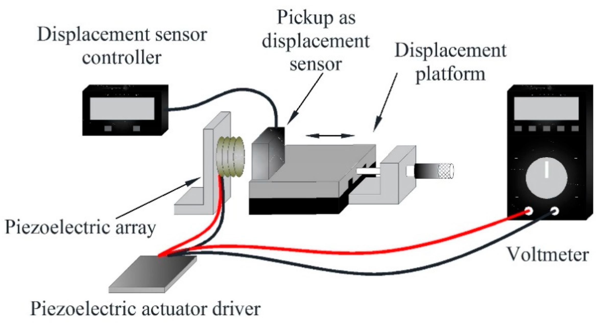
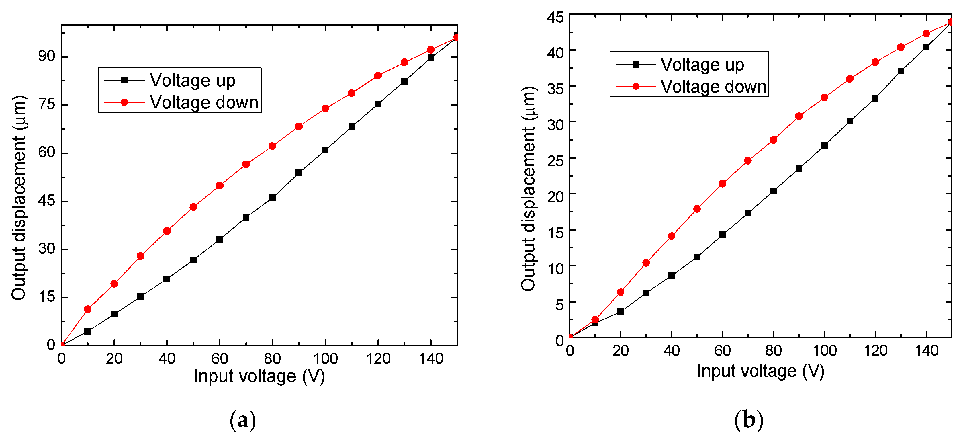
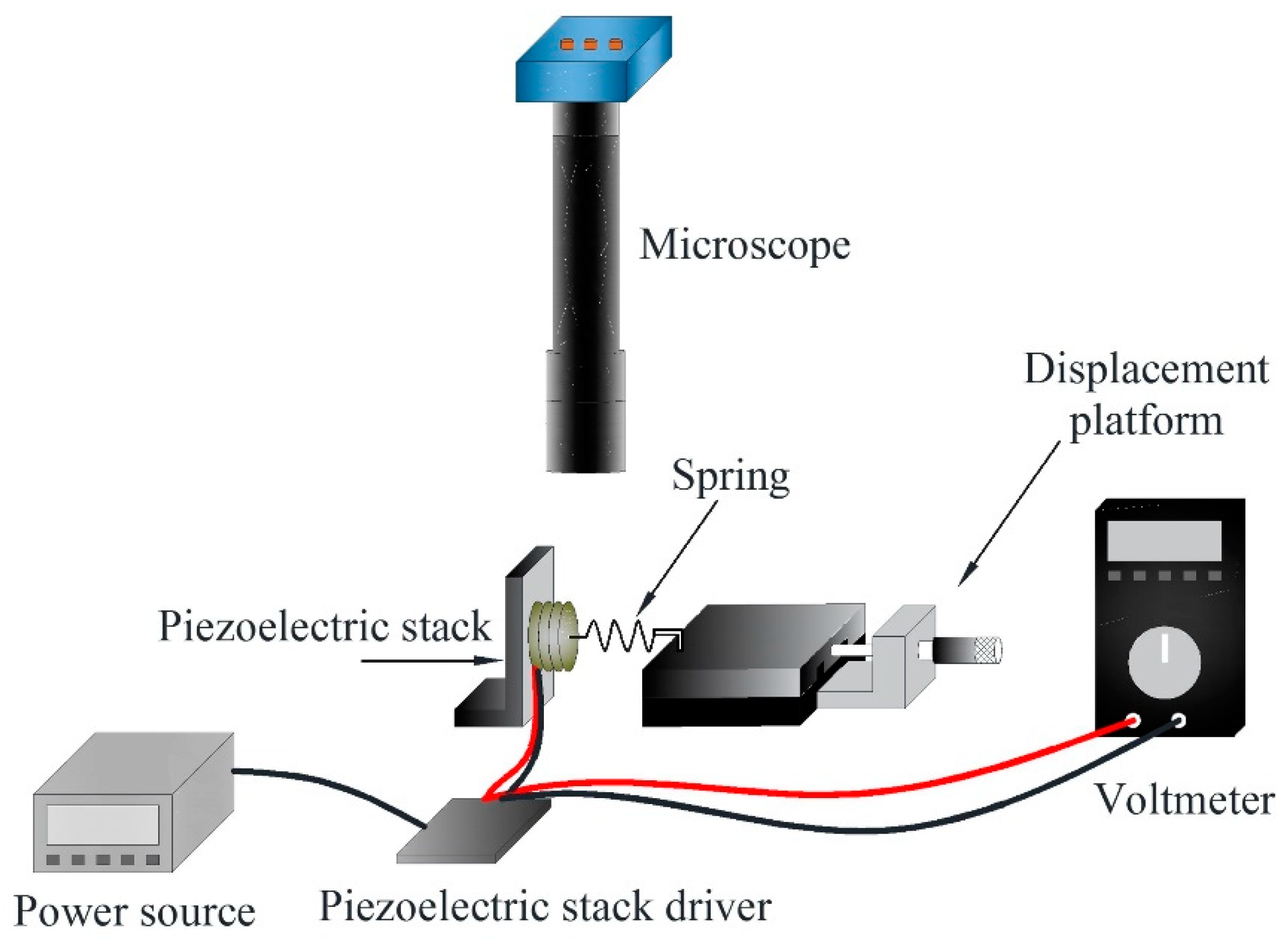
From our experimental tests with piezo buzzers shown in Table 2, the obtained linear displacements exceed some commercial piezoelectric actuators’ response. These measurements were obtained with the experimental setup shown in Figure 2; the corresponding deformations are shown in Figure 3.
From Figure 3, the difference of displacements on the X and Y axes compared to Z-axis is observed. A decrement of displacement of 45.7% is obtained on the Z-axis. In both graphs, the hysteresis behavior proper to piezo actuators is also shown. The size dimensions differ by 33.3%.
The case of arrangements of piezoelectric actuators has been also analyzed. In [44], the graph of force versus displacement is shown, indicating that when large forces are required, the displacement is decreased.
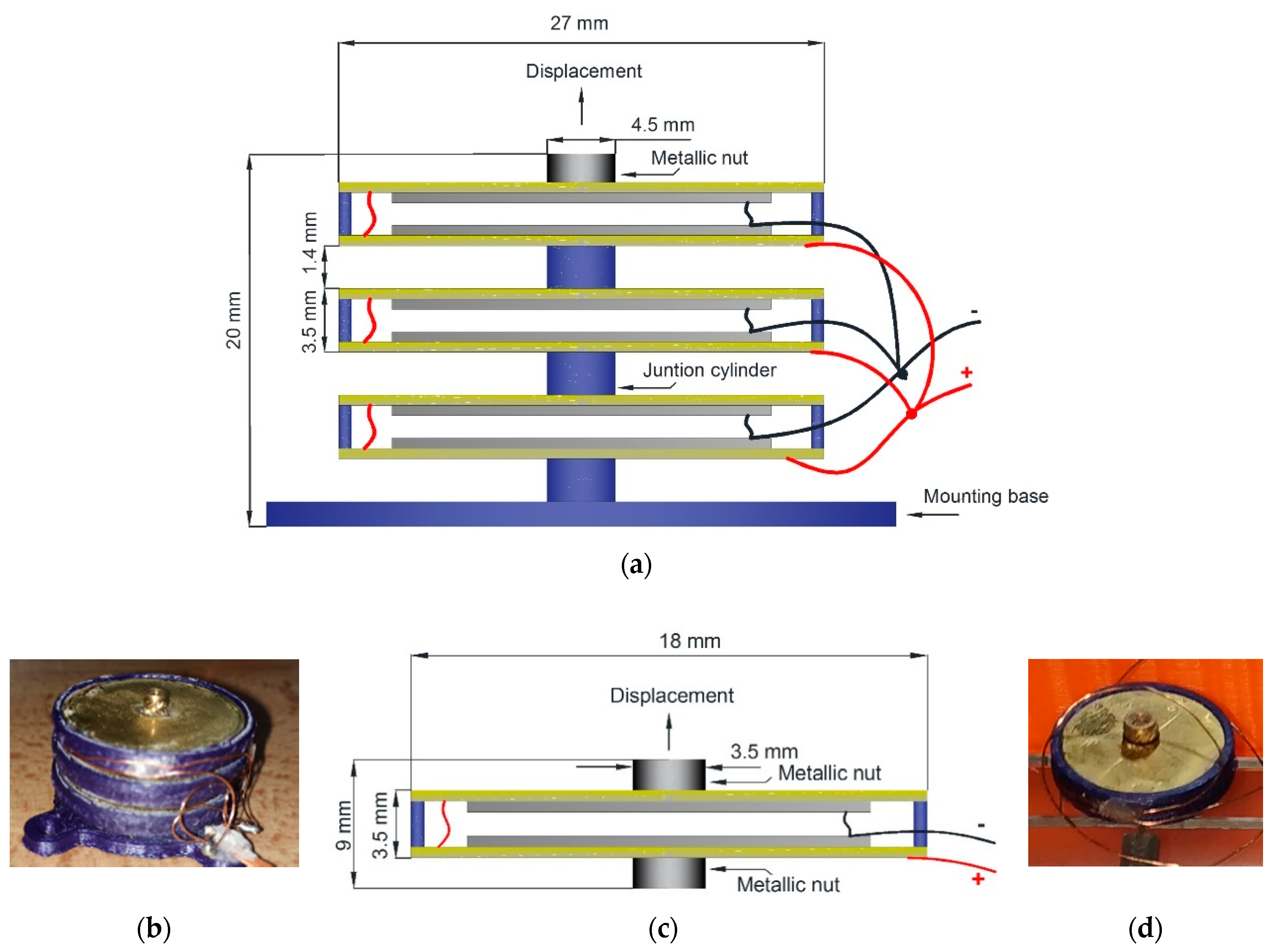
In our case, the large displacement required makes it necessary to design a piezo buzzer stack type actuator to improve the individual characteristics of the piezo buzzers. For movement on the X and Y axes, the design consists of a parallel arrangement of six piezo buzzers, located inside a designed Polylactic Acid (PLA) structure, fabricated by additive manufacturing process (Figure 4a). In each piezo buzzer, the brass disc is used as an impulse membrane of vertical displacement. Figure 4b shows the implementation of these parallel arrangements.
When the stack is fed, each buzzer is deformed as depicted in Figure 1b. The union cylinders were placed in the zone of maximum deformation to generate the maximum possible displacement.
For the case of the Z-axis, an arrangement of two piezoelectric buzzers was enough for our purpose (Figure 4c,d) because, generally, in the manufacturing process, for example, using Computer Numeric Control (CNC), the larger displacements correspond to X and Y axes. The displacement on the Z-axis is lower since the grabbing tool generally requires small displacements. Besides, some grabbing tools have their own automated or manual control of position along the Z-axis [3,45].
For the stack tip, a metal nut was selected, whose thread serves to hold the element to be moved. The small diameter size of this nut was sought. There are commercially, locally available nuts of 3 mm in diameter, which do not strongly affect the stack deformation. Lower diameters will not restrict the stack deformation.
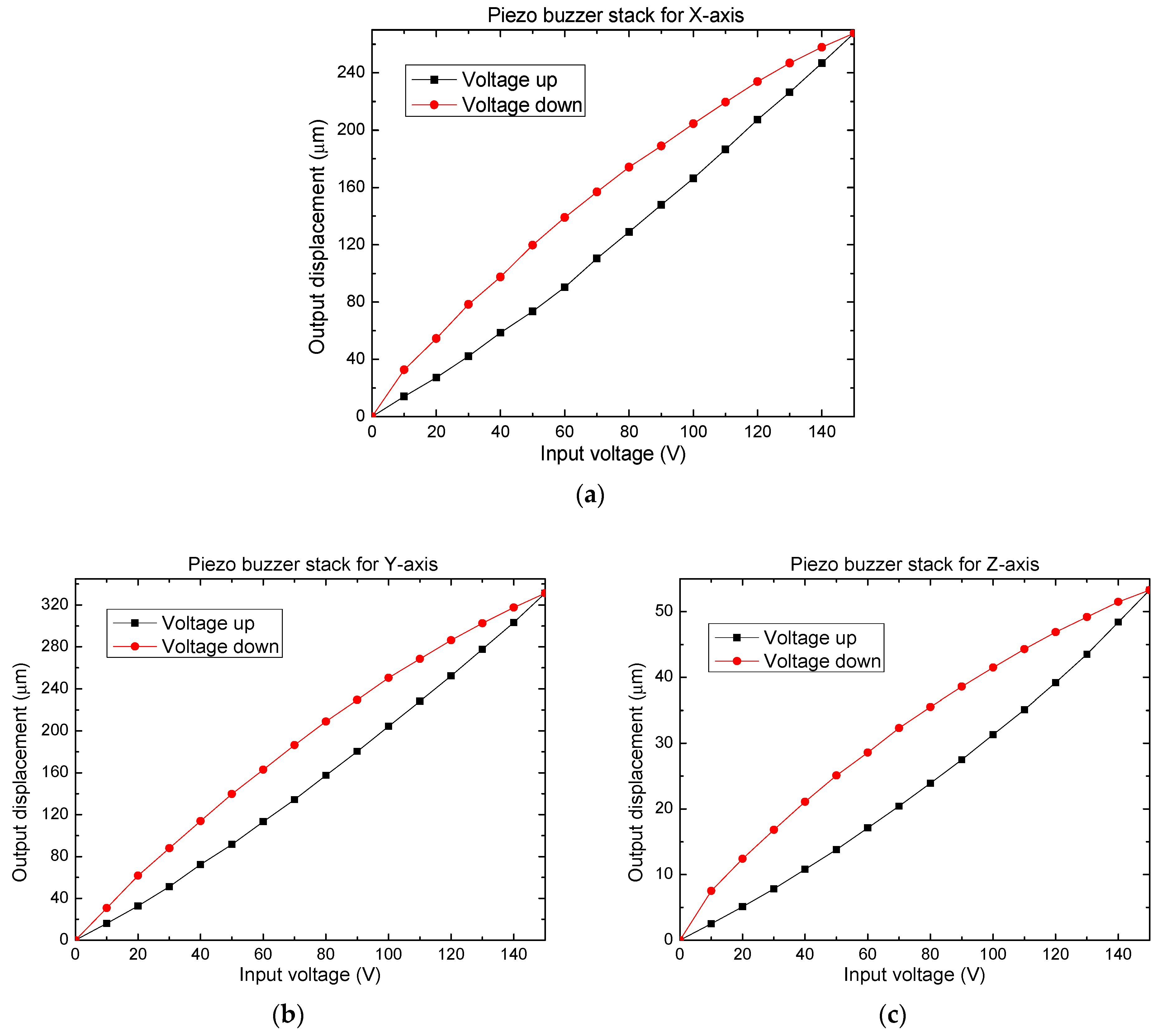
The experimental arrangement used to determine the displacement of the three piezoelectric actuators corresponding to the X, Y, and Z axes are shown in Figure 2. The results corresponding to the displacement in each axis are shown in Figure 5. A low-cost optical displacement sensor, implemented with a Pickup, which achieves a resolution of 100 nm, was used to measure the displacement behavior of the stack actuators. Pickups as displacement sensors are good options to perform precise measurements, as it has been proven by [46,47,48].
The data collected from displacements (Figure 5), allow us to observe the difference in magnitudes between the displacements on the Z-axis, concerning the X and Y axes. The maximum mean value of the displacements on the X and Y axes is 300 μm, and on the Z-axis, the maximum value of displacement corresponds to 53.3 μm, which is enough for our purposes. The difference in these values is produced by the different disk sizes, as well as, by the different number of buzzers used in each case.
There is a little variation in the maximum displacement on the X and Y axes, as a result of the quality of the assembly and the differences in the positioning of the piezoelectric element inside the brass disks, however, this fact does not represent a major problem because it is possible, with an external control system, to homologate these responses [49]. Stack manufacturing repeatability can be improved through automated assembly processes. Additionally, the quality of 3D printing can be improved by extending manufacturing times and reducing the diameter of the nozzles for higher resolution.
A comparison of the displacements between individual piezo buzzers and piezo buzzer stacks is given in Table 3.
All the piezo buzzer stacks (for X, Y, and Z axes) do not achieve the total expected displacement according to the total number of buzzers used in each case, generating a significantly large error between their calculated and measured values. The measured displacements of the piezo buzzer stacks are lower than the calculated, which can be mainly attributed to the cylindrical joints (with diameters of 4.5 mm) used between each piezoelectric buzzer, as mentioned above, these elements reduce the total deformation. It should be noted that six cylindrical joints are used for the stacks designed for the X and Y axes, while only two cylindrical joints are used for the Z-axis case.
About the repeatability of displacement generated by stacks, only two stacks of six piezo buzzers and two of four piezo buzzers were available. The corresponding measurements are given in Table 4.
The average values of displacement for each pair of piezo buzzers have similar error values. To achieve sufficient repeatability, a proper selection process of buzzers should be considered based on their displacement and not only on their geometric characteristics and the location of the junction point between its plates, as well as reducing the PLA cylinders to the minimum, used as axial unions, or replacing them, using other materials or elements. For the elaboration of each stack, a correction factor must be obtained on the displacement and the force applied in each axis.
The forces generated by individuals and stacks of piezo buzzers are measured with the experimental setup of Figure 6. Results are shown in Table 5.
From Table 5, for the case of individual buzzers, the bigger force corresponds to the buzzer actuators of larger diameters, which are used for the X and Y axes. In the same Table, the error between the calculated and measured force of the piezo buzzers is given. The analytical values are calculated considering the addition of the displacements generated by the individual piezo buzzers in the stack. For the piezo buzzer stacks, again, the bigger force corresponds to piezo buzzer stacks for the X and Y axes, as they have six buzzers of larger sizes compared to the Z-axis ones, which only have two buzzers. Some losses are observed, which are mainly attributed to the connector’s diameters, which restricted the total deformation.

3. Micropositioning Design

The design procedure was based on simulation, to obtain symmetric displacements of the working platform, under the following considerations:
For the movement of the working platform, the input force for each axis is generated by the corresponding piezo buzzer stack actuator, which is transmitted through flexible mechanisms, designed by generating symmetric displacements on the X and Y axes. The micropositioner activation method is classified as a direct actuation mode [33].
Due to the low force required to move the flexible elements of the micropositioner and the high displacement of the piezo buzzer stack actuator, it was not necessary to use additional movement amplification mechanisms. The demand for extra force causes a decrease in the displacement of the piezoelectric actuator because it generates a little force (the blocking force on the X and Y axes is 1.27 N).
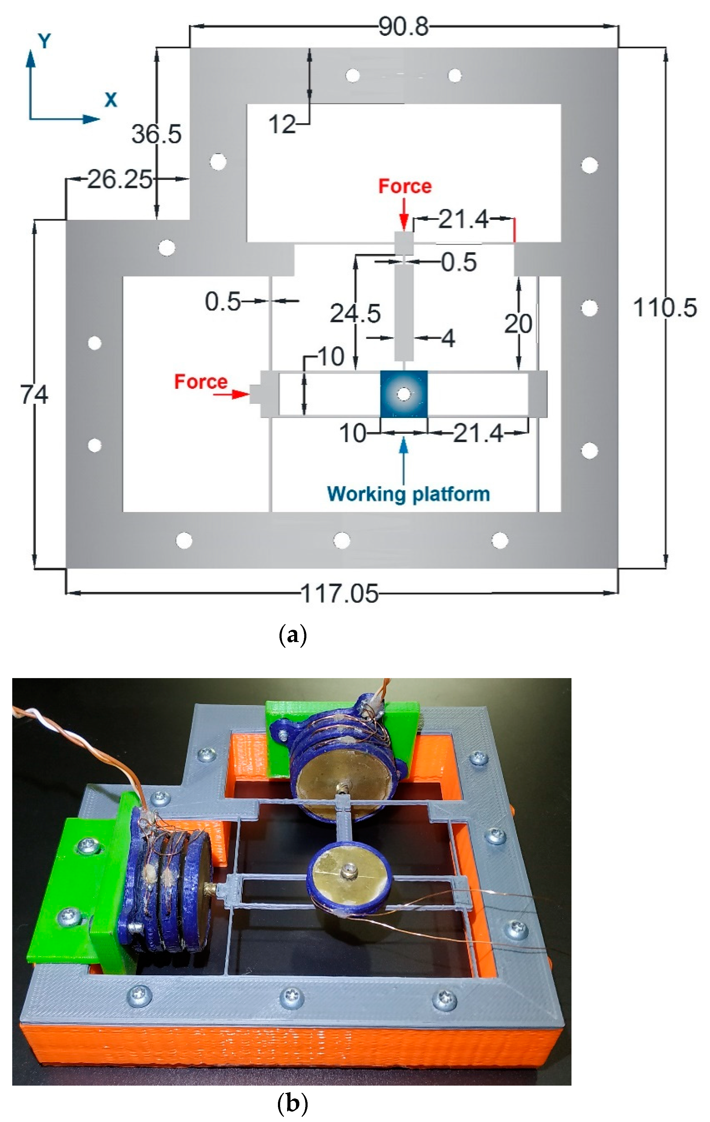
The design of the micropositioner is shown in Figure 7, which is essentially composed by:
  • Support for piezo buzzer stack actuators.
  • A working platform (mobile support), where the samples are placed.
  • A set of flexible elements for the movement on the X-axis.
  • A group of flexible elements for the movement on the Y-axis.
  • The Z-axis piezo buzzer stack actuator is located above the work platform.
Holes on the contour of the platform have two functions: (1) Subject the base support, and (2) fix the base of piezo buzzer stacks.
This small positioner has a simple geometry and one reasonable symmetric response on the X and Y axes, despite the differences in the configurations on the X and Y axes. A completely symmetric parallel mechanism is commonly used. An advantage of our arrangement is the lower size of the complete positioner and a small number of compliance elements. This prototype is also differentiated by the piezo buzzer stacks and the chosen materials.
Considering the low force that the piezo buzzer stack actuators can deliver, a flexible material was chosen to achieve a minimum loss of force and, therefore, a greater displacement of the working platform. Initially, the selected material was PLA, which is preferentially used for additive manufacturing, due to its characteristics such as biodegradability under ideal conditions [50], simplest printing process, and providing significant energy savings in its production, compared to other materials used in Additive Manufacturing (AM) [51]. Another example of a piezo buzzer stack can be found in [52].
However, when operating the XYZ micropositioner made with PLA, a moderate loss of displacement was recorded in both axes. To achieve the maximum displacement that the actuators reach, it was necessary to change the material of the flexible elements, in this case by ABS, which is a polymer made by polymerizing styrene and acrylonitrile in the presence of polybutadiene. ABS has a lower Young’s Modulus than PLA, with a consequent lower resistance to bending.

3.1. Micropositioner Model

The main consideration of design was to provide symmetric displacements to the working platform, on the X and Y axes. This goal was obtained using a different configuration of compliance mechanisms on each axis. This central design determines the shape of the external contour, but it can be replaced by any other geometric shape, following the user’s requirements.
In the micropositioner (Figure 7a), all the suspended elements, arms, and contours of the micropositioner have a thickness of 0.5 mm. Figure 7b shows the positioner implementation using PLA.
The Square working platform was chosen to favor the symmetry of the movements, and its length was chosen as 1 cm2 to provide sufficient space for samples of micrometric and even millimeter sizes.
Symmetry response was privileged in both axes supports of the working platform.

3.2. Displacement on Y-Axis

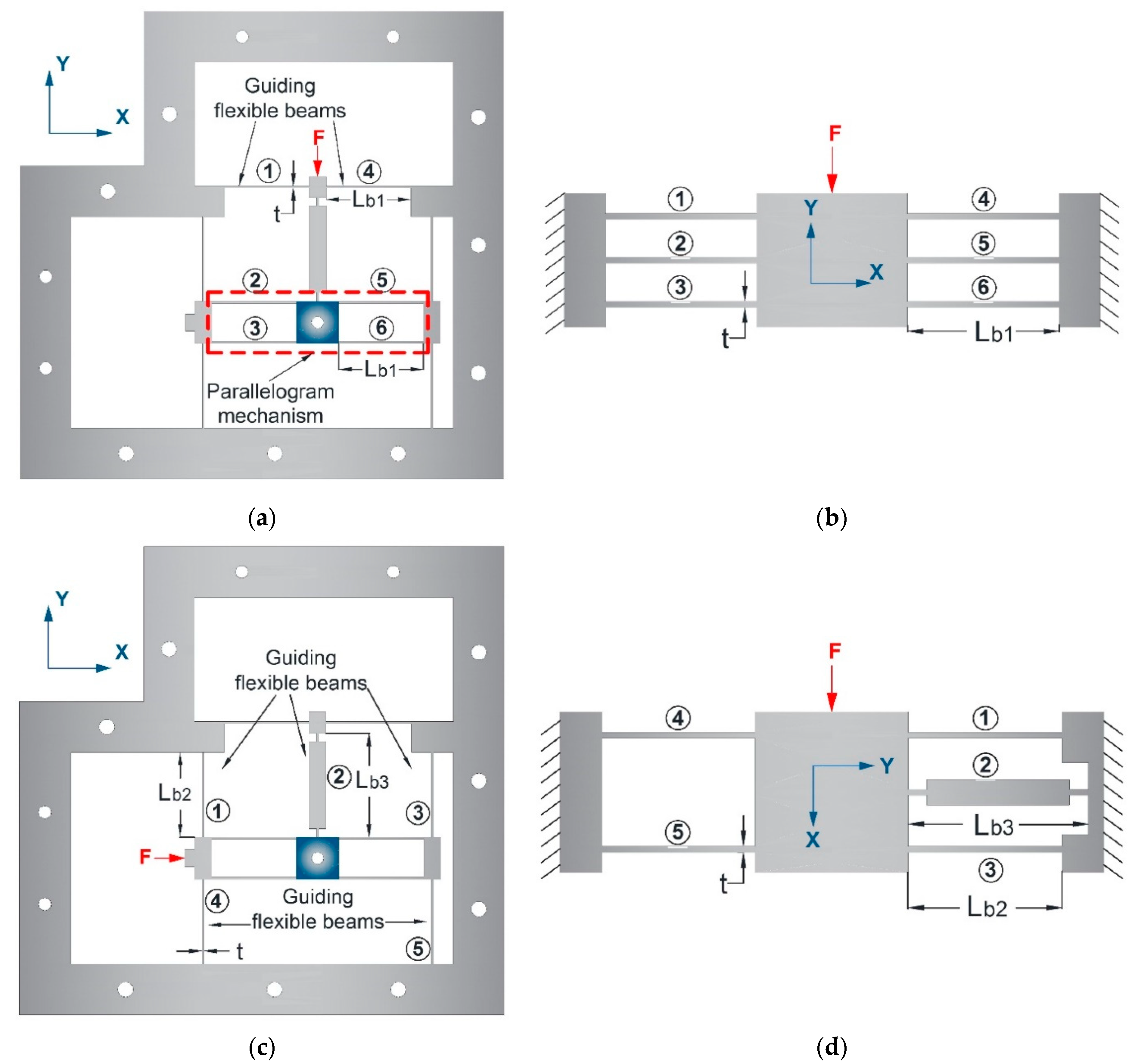
Using a simplified equivalent model of the guiding mechanisms (Figure 8), we obtained it on the basis of [53,54].
For each beam of transversal area w∗t, where w is the width and t, the thickness, the inertia moment I b 1 is calculated by the well-known relationship [55,56]:
I b 1   =   w t 3 12
The stiffness of a single beam of length l b 1 is given by:
k b 1   =   12 E I b 1 L b 1 3
where L b 1 is the length of the beam.
The equivalent stiffness of the 6 guiding parallel beams of length L b 1 of the working platform that determines the displacement on the Y-axis (Figure 8a,b) is expressed as:
k e q Y   =   6 k b 1   =   72 E I b 1 L b 1 3
Displacement of the working platform on the Y-axis is given by the Hooke law, as [53,54,56]:
Y = F k e q Y

3.3. Displacement on X-Axis

In this case, five guided beams are considered (Figure 8c,d). The equivalent stiffness, in this case, is given by:
k e q X = 4 k b 2   + k b 3   = 48 E I b 2 L b 2 3 + 12 E I b 3 L b 3 3
L b 2 and L b 3 are the corresponding lengths of the beams.

4. Micromicropositioner Simulation

The design of the micropositioner was simulated in ANSYS ™ to specifically validate the performance of the flexible mechanisms, which provide the displacement on the X and Y axes, and also to optimize the dimensions of their flexible elements, as well as to know the modal frequencies of the structure [57]. The mechanical properties of the materials used are given in Table 6, where it is important to mention that the research about the design used for additive manufacturing with ABS is very extensive and the values shown were obtained experimentally in the respective references, while in the cases of PETG and PLA, the values were provided from the manufacturer’s datasheet.

4.1. Static Structural Analysis

Simulation processes were performed in ANSYS using ABS. Since this material has a lower Young’s modulus than the other materials considered, it has greater flexibility of compatible mechanisms. One symmetrical behavior of the flexible design was sought in both axes. After obtaining a functional design, PLA and PETG were also used to compare results.
During the simulation with ABS, the behavior was analyzed, and key elements were identified that were modified to improve the performance in terms of a minimum input force with a maximum displacement at the output. The von Mises stress distribution has lower values than the Field Yield Strength.
To check the symmetric behavior of the micropositioner, two measurement procedures were carried out in the simulation in ANSYS. In the first one, two simulations were performed, using separated applied forces in each axis. Under this condition, the perpendicular axis displacement does not interfere with the axis under analysis. In Figure 9 and Table 7, the obtained results are given.
In the second procedure, both input forces were applied simultaneously, and for this case it was of interest to observe the displacement on both axes to check if the symmetry obtained applying separated forces was maintained. In Figure 10 and Table 5, the results of the directional deformation in the X and Y axes are provided.
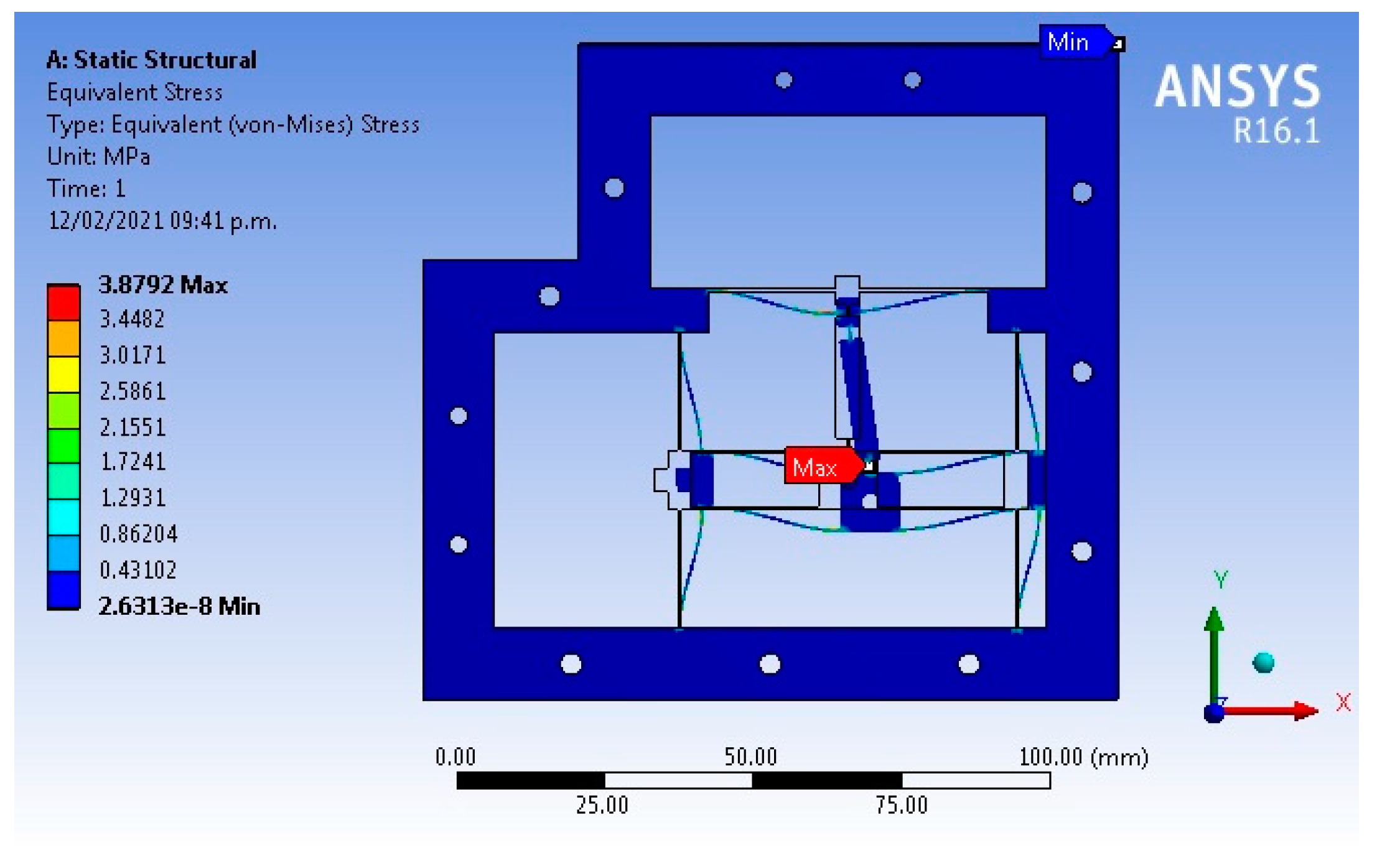
Figure 11 shows the maximum equivalent stress, generated by applying the forces in the X and Y axes simultaneously. The maximum value, 3.87 MPa, is very low, compared to the corresponding Field Yield Strength value. The maximum value of stress was obtained when both forces were simultaneously applied.
In Table 7, the results obtained from simulations of the micropositioner implemented with ABS, PETG, and PLA are also presented.
The data shown in Table 7 indicate that for each micropositioner implemented in different materials, when equal forces are applied individually to each axis, similar displacements are generated (displacement differences in absolute values differ in a range of 1 to 2 µm). When both forces are applied simultaneously, the differences are slightly larger (2 to 6 µm). In general, it is observed that the axis that presents the greatest resistance to deformation is the X-axis because this is the one with the least symmetry, which also implies a slightly asymmetric behavior. In general, the variations are very low, of the order of 1.19%.
For ABS, from Equation (4), using F = 0.1 N for X and Y displacements, the results are given in Table 8. It can be observed that the level of approximation for theoretical and simulated values is very near, lower than 5%. It is important to mention that for the X-axis, the parallelogram model was used, but for the Y-axis, a new nonsymmetrical configuration was considered, therefore its performance is slightly different, and this implies that our model has a bigger error than the previous one, but with an acceptable value. The main advantage of using this model is the obtained reduced area, on the opposite side of the guiding flexible beams.
To add experimental values to Table 8, input forces of 0.1 N were applied to the working platform. The displacement of the platform was manually measured. Some reasons for the obtained errors could be attributed to the precision in the measurements, as well as the precision of the fabrication process and the non-isotropy of the materials.
From Table 8, it is possible to observe that the biggest symmetry on the displacements is obtained for PETG, but lower displacement compared with ABS. The analytical model for the case of the X-axis shows a different trend that is followed by the simulated and experimental cases. Our approximations need to be improved, fortunately, the error compared with simulation results is very small; in all cases, it is lower than 5%.
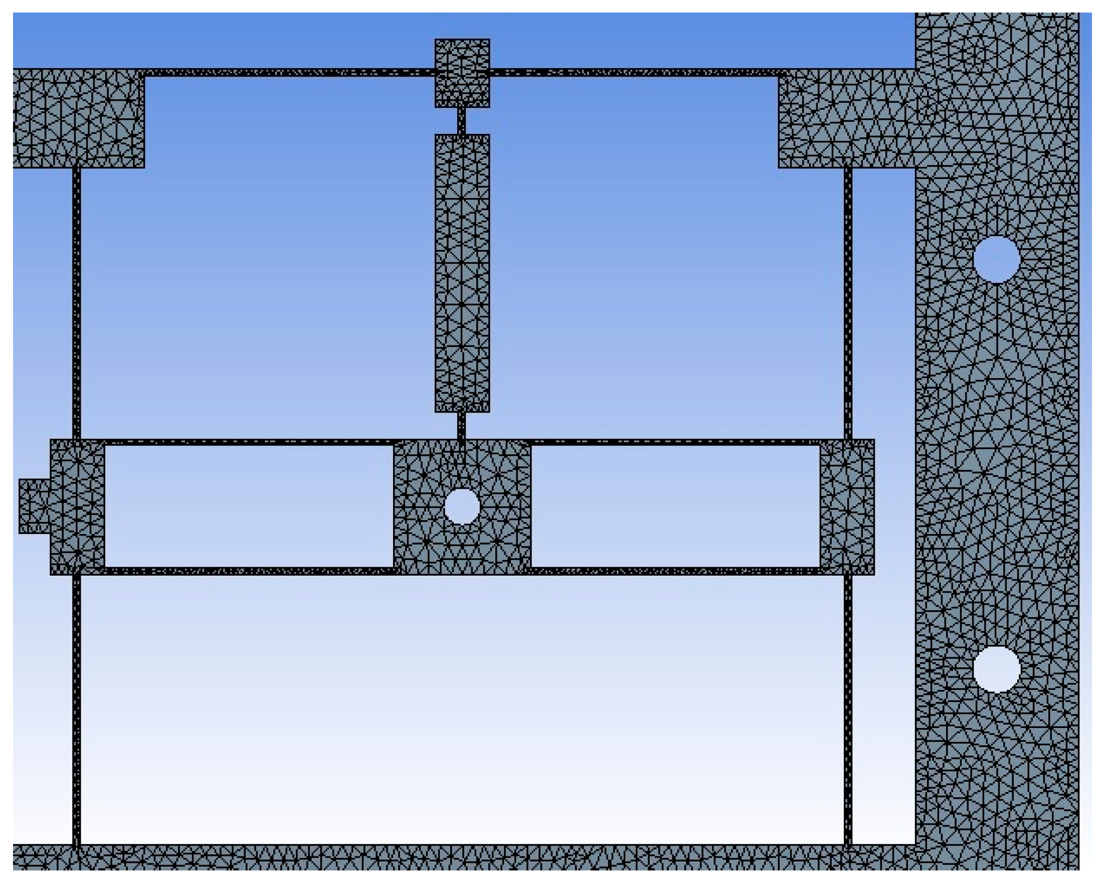
Technical details about FEA analysis are provided in Table 9. Our values of skewness and orthogonal quality of mesh are very good, in accordance to skewness and orthogonal quality mesh metric spectrums given in [65], as they are inside of the range 0.25–0.50 and 0.70–0.95, respectively. An image of the mash is given in Figure 12. The initial mesh is appropriated providing a sufficient resolution to accurately model geometric and material nonlinearities [66]. The displacement obtained by simulation in X and Y axes have larger values of approximately 300 µm, which are lower than half of the beam thickness (1.5 mm), which allows us to consider it as a unidimensional object [67].

4.2. Modal Analysis

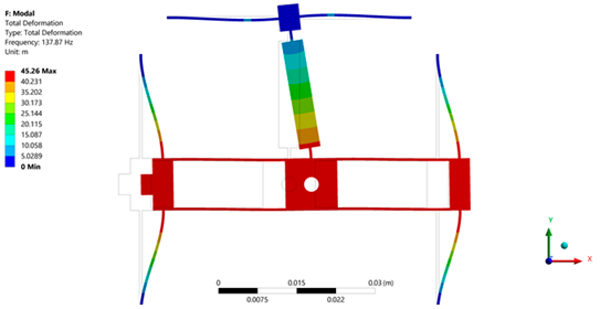
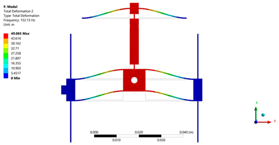
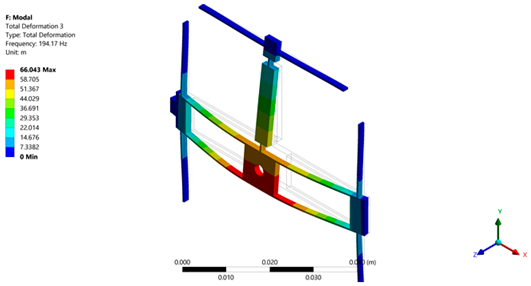
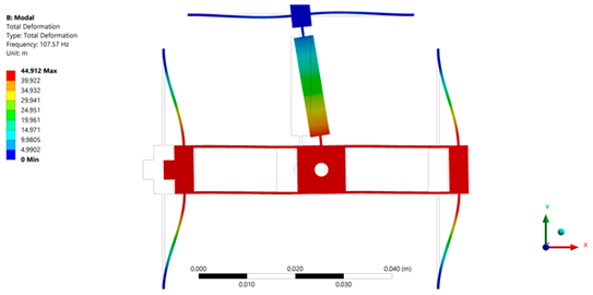
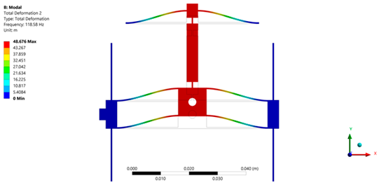
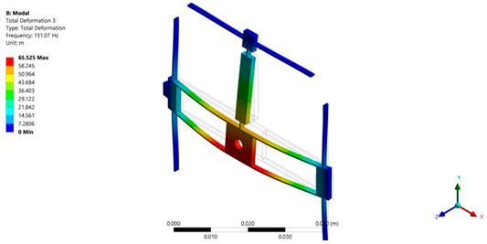
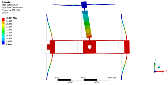
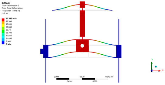
If the platform will be used in processes where vibrations are present or when forces are applied under relatively high frequencies, as it could be the case for laser machining, the frequency response of the micropositioner must be known to determine the frequencies that limit their operation [68], so in this section the modal shapes for the micropositioners implemented with the three materials are determined.
The value of the suspended mass or mass of the working platform (0.20 g), plus the piezo buzzer stack mass (2.03 g) used in the Z direction, provides the total mass of 2.23 g.
The boundary conditions for obtaining the modal forms are the fixed ends of the beams and the consideration of the device under analysis without load.
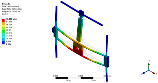
For the micropositioner designed with PLA, according to the first three modal frequencies given in Table 10, which also provide the expected movements in axis, it is determined that the operating frequency should not reach 137.87 Hz. For the case of PETG, the lower frequency corresponds to 107.67 Hz, and for ABS, to 108.33 Hz. As can be observed, the lower value of frequency corresponds to PETG.
In Table 11, technical details about simulation in ANSYS are shown.
In Table 12, a comparison between the performance of micropositioners implemented with PLA and ABS is given. Based on these results, the positioner of ABS was chosen, as we are focused on displacement, and the reduction of frequency, compared with the response of PLA positioner, which is not relevant.

5. Experimental Results

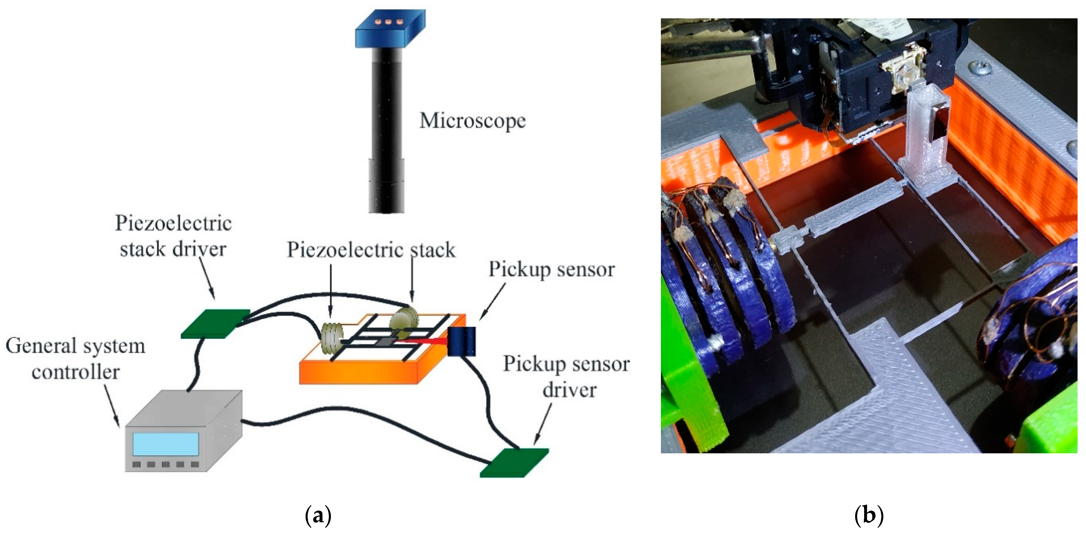
The experimental setup designed to record the micropositioner displacement on the X, Y, and Z axes is shown in Figure 13a. To achieve comparable results, the piezo buzzer stack actuator with the largest displacement was used to obtain the displacement on the X and Y axes. The pickup sensor was used to register the displacements in these axes, and a microscope to monitor the displacement. Since the lateral space of the working platform is too small to place the pickup sensor at an operating distance, a lightweight PLA block was placed on the working platform with a piece of highly reflective material placed on one of its sides to receive the laser beam (Figure 13b).
The microdisplacement platform, made up of compliance elements, is removable. It is placed on perimeter support made of PLA through screws; the support is not a critical element on the micropositioner performance, then it can be manufactured with a polymeric material or metal.
The stack piezoelectric actuators designed for movements on the X or Y axes are fixed on the appropriate location on the contour of the micropositioner device. They are at first individually fed with 0 V to 150 V, with increments of 10 V. The displacement of the working platform is measured at each increment of voltage. When 150 V is applied, the potential difference was progressively decreased with steps of 10 V, and again the displacement values of the working platform were recorded. This procedure was applied to both axes of the micropositioner independently.
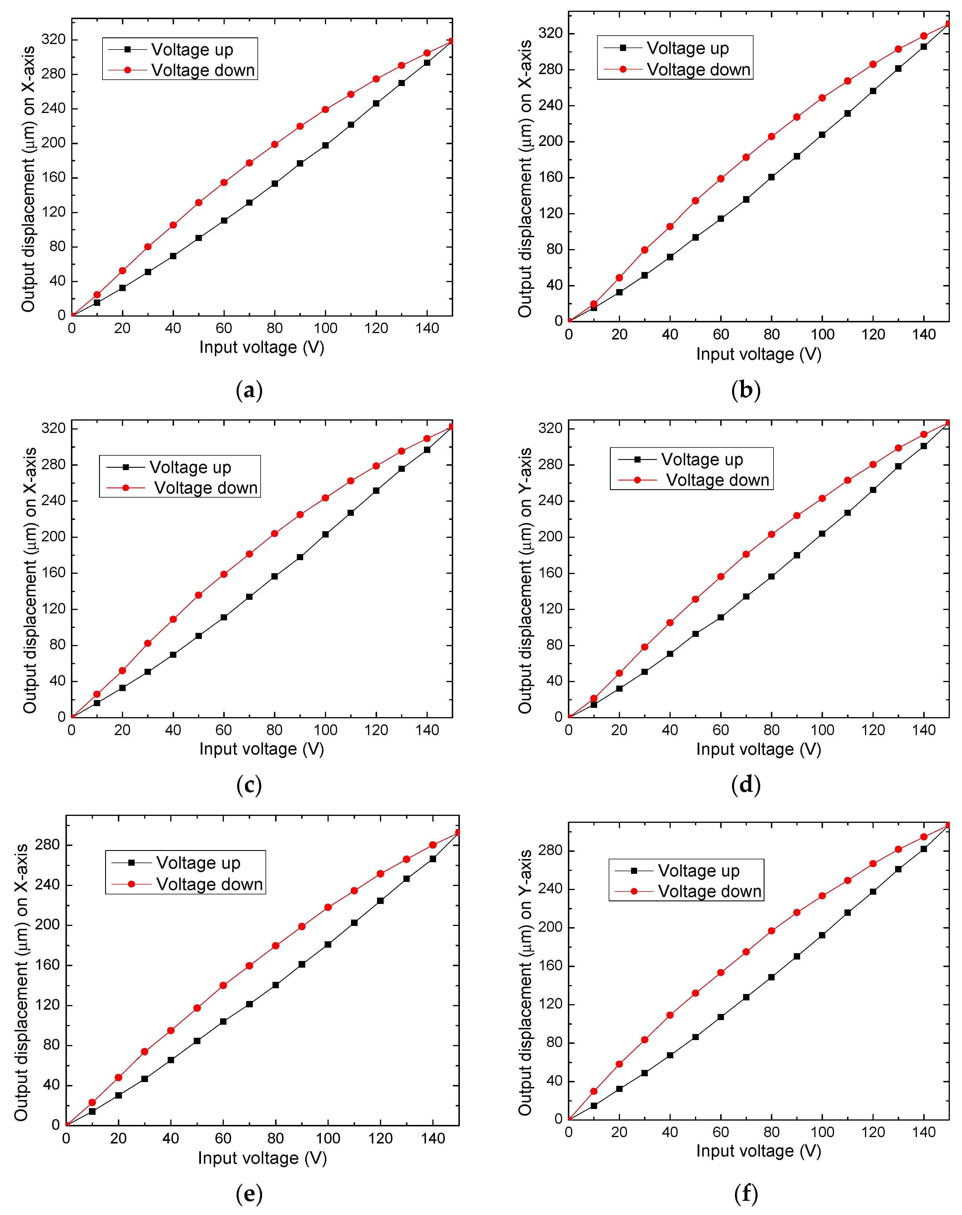
To validate the choice of ABS as the structural material for the micropositioner fabrication, three prototypes were fabricated using ABS, PETG, and PLA. With each one, the displacement measurements were carried out. Displacements on the X and Y axes are provided in Figure 14, for each case. The results comparison is given in Table 13, considering the maximum displacements.
From Figure 14 and Table 9, it is observed that the symmetric movements on the X and Y axes are maintained by the three prototypes since, for all cases, the values of displacement on both axes are very close. The error value is smaller for PETG (1.52%), while the larger corresponds to PLA (4.92%). Previously, it was considered to choose ABS for fabrication, because, with this material, the largest displacements were obtained, and this selection is maintained, in this case, due to the small error in symmetric displacements on the X and Y axes. Resolution on movements is determined by pickup sensor, model SF-P151, SANYO, with a resolution of 100 nm.

Linearization of Displacement of the Piezoelectric Actuator

A control system can be used, either in a closed or open loop, to compensate for the hysteresis effect, characteristic of the piezoelectric actuator.
In closed-loop, high resolution and precision sensors are required to generate a feedback signal to the control system, for example, a microcontroller, which performs the necessary corrections to achieve the magnitude of the desired displacement. With this system, high output precision can be achieved, however, the cost of the system increases with the use of sensors and additional electronics.
On the other side, about the open-loop control system, its basic implementation does not require any sensor, but it is necessary to know the detailed behavior of the piezoelectric actuator when it is subjected to variations of electric potential. With this information, the displacement of the actuator is mathematically modeled, since that, the programming of the microcontroller is performed to execute the established operations.
Due to the low-cost approach of the proposed micropositioner, it was decided to improve its precision using an open-loop control system. The method used is basic, but it provides a level of precision enough to reduce the hysteresis effect. It was designed for an electric potential increase condition. A complete model can be used for the case of increase and decrease voltage conditions, as reported in [69].
The method determines the voltage values required to obtain linear displacements in the established range.
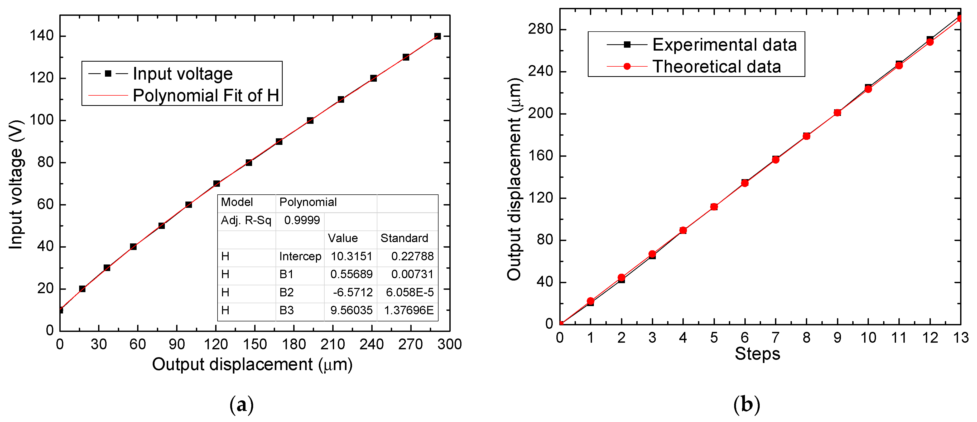
The first step is to invert the graph, using the output displacement of the piezo buzzer stack versus the input electric potential. Subsequently, the order of a suitable polynomial is calculated to achieve an approximation that accurately reproduces the hysteresis curve corresponding to the increase of voltage, as shown in Figure 15a.
Finally, an algorithm for the control system is made by implementing the calculated polynomial function. The algorithm must be able to meet the requirements, that is, to generate linear displacements by evaluating the polynomial function to apply the calculated electric potential to the piezo buzzer stack actuator. In Figure 15b, the results achieved are presented, on the Y-axis of the micropositioner, with the implementation of the basic linearization method. The number of steps corresponds to the desired offset, with increments of 22.3 µm. Because the correlation coefficient between the experimental value and the analytical value is high, 0.99997, the linearization model provides a feasible option to compensate for the hysteresis effect of the used piezoelectric actuators.

6. Conclusions

The use of piezoelectric buzzers allows us to develop piezo stack actuators, based on them, of low cost. Different sizes of piezo buzzers allow us to design piezo stacks for different displacement requirements, in this case, larger displacement corresponds to the X and Y axes, and lower for the Z-axis.
In aleatory samples of piezo buzzers, there is a small variation in the internal diameters, and especially in the internal location of PZT. Therefore, a careful selection is necessary before assembling the stacks.
These piezo stacks provide large displacements, more than most commercial options; however, the generated force is much lower, therefore, their applications are limited by this characteristic.
The support structure of the piezo stacks can be improved to generate the expected summation of the individual displacements of the piezo actuators or layers that form it.
The simulation was used as a design tool, to determine the compliance arrangement to provide symmetric response on the displacement of the working platform on the X and Y axes.
For the prototypes implemented in simulation, with ABS, PETG, and PLA, the compliance elements provided symmetric displacements to the working platform, with a percentage of error lower than 5%, with a minimal (1.52%) for PETG. ABS and PETG provided the largest displacements in simulation.
Simulation with ABS positioner was performed to determine the modal frequencies to obtain the conditions for maintaining the integrity of the micropositioner.
With the experimental setup, the largest displacements of the working platform on the X and Y axes also corresponded to prototypes made with ABS and PETG.
An open-loop control was designed and implemented to linearize the displacement when electric potential increases condition, with high correlation values, that shows its precision level.
As future work, this micropositioner can be integrated into a microgripper to obtain a complete micromanipulation system of low cost. A PID control system would be also added, to compensate the hysteresis effect to increase the precision of the positioning.

Author Contributions

Conceptualization, A.F.-B. and M.T.-T.; formal analysis, A.F.-B., P.V.-C., G.V.-D., R.V.-B. and M.T.-T.; funding acquisition, M.T.-T.; investigation, A. F.-B; methodology, G.V.-D., and M.T.-T.; project administration, M.T.-T.; software, A.F.-B. and P.V.-C.; Validation, P.V.-C., and G.V.-D.; Writing—original draft, M.T.-T.; Writing—review and editing, R.V.-B. All authors have read and agreed to the published version of the manuscript.

Funding

This research was funded by Consejo Nacional de Ciencia y Tecnologia, CONACyT, grant reference number A1-S-33433. “Proyecto Apoyado por el Fondo Sectorial de Investigación para la Educación”.

Institutional Review Board Statement

Not applicable.

Informed Consent Statement

Not applicable.

Conflicts of Interest

The authors declare no conflict of interest.

References

  1. Muro, H. History and Recent Progress of MEMS Physical Sensors. Adv. Sci. Technol. 2012, 81, 1–8. [Google Scholar] [CrossRef]
  2. Sitapure, N.A.; Malani, S.; Goswami, P.A. Review of the Foundation Technologies of Nano-Electronics. Int. J. Appl. Sci. Eng. 2016, 5, 29–42. [Google Scholar]
  3. Daffé, K.; Dambrine, G.; von Kleist-Retzow, F.; Haddadi, K. Impact of piezoelectric nano-positioner displacement accuracy on On-wafer S parameters repeatabilities. EMPIR Project 14IND02 PlanarCal. EMPIR Euramet Germany. Available online: https://planarcal.ptb.de/fileadmin/documents/empir/14Ind02/documents/Meetings/20160623_Delft/presentation_workshop_230616_dambrine.pdf (accessed on 13 March 2021).
  4. Jia, Y.; Xu, Q. MEMS Microgripper Actuators and Sensors: The State-of-the-Art Survey. Recent Patents Mech. Eng. 2013, 6, 132–142. [Google Scholar] [CrossRef] [Green Version]
  5. Liu, Y.; Deng, J.; Su, Q. Review on Multi-Degree-of-Freedom Piezoelectric Motion Stage. IEEE Access 2018, 6, 59986–60004. [Google Scholar] [CrossRef]
  6. Shi, C.; Luu, D.K.; Yang, Q.; Liu, J.; Chen, J.; Ru, C.; Xie, S.; Luo, J.; Ge, J.; Sun, Y. Recent advances in nanorobotic manipulation inside scanning electron microscopes. Microsyst. Nanoeng. 2016, 2, 16024. [Google Scholar] [CrossRef] [PubMed] [Green Version]
  7. Wu, Z.; Xu, Q. Survey on Recent Designs of Compliant Micro-/Nano-Positioning Stages. Actuators 2018, 7, 5. [Google Scholar] [CrossRef] [Green Version]
  8. Chaillet, N.; Régnier, S. Microrobotics for Micromanipulation, 1st ed.; Wiley: Hoboken, NJ, USA, 2013; pp. 179–242. [Google Scholar] [CrossRef]
  9. Dochshanov, A.; Verotti, M.; Belfiore, N.P. A Comprehensive Survey on Microgrippers Design: Operational Strategy. J. Mech. Des. 2017, 139, 070801. [Google Scholar] [CrossRef]
  10. Xu, Q. A novel compliant micropositioning stage with dual ranges and resolutions. Sens. Actuators A Phys. 2014, 205, 6–14. [Google Scholar] [CrossRef]
  11. Sun, F.; Hao, Y.; Xu, F.; Jin, J.; Li, Q.; Tong, L.; Zhang, M.; Zhang, X. Proposal of An Equal-Stiffness and Equal-Stroke 2D Micro-Positioning Platform Driven by Piezoelectric Actuators. Actuators 2020, 9, 47. [Google Scholar] [CrossRef]
  12. Wan, S.; Xu, Q. Design and analysis of a new compliant XY micropositioning stage based on Roberts mechanism. Mech. Mach. Theory 2016, 95, 125–139. [Google Scholar] [CrossRef]
  13. Zhang, X.; Zhang, Y.; Xu, Q. Design and control of a novel piezo-driven XY parallel nanopositioning stage. Microsyst. Technol. 2017, 23, 1067–1080. [Google Scholar] [CrossRef]
  14. Kenton, B.J.; Leang, K.K. Design and Control of a Three-Axis Serial-Kinematic High-Bandwidth Nanopositioner. IEEE/ASME Trans. Mechatron. 2011, 17, 356–369. [Google Scholar] [CrossRef]
  15. Guo, Z.; Tian, Y.; Liu, C.; Wang, F.; Liu, X.; Shirinzadeh, B.; Zhang, D. Design and control methodology of a 3-DOF flexure-based mechanism for micro/nano-positioning. Robot. Comput. Manuf. 2015, 32, 93–105. [Google Scholar] [CrossRef] [Green Version]
  16. Al-Jodah, A.; Shirinzadeh, B.; Ghafarian, M.; Das, T.K.; Pinskier, J. Design, modeling, and control of a large range 3-DOF micropositioning stage. Mech. Mach. Theory 2021, 156, 104159. [Google Scholar] [CrossRef]
  17. Chen, B.; Lee, M.; Tong, H.; Hang, C.-C.; Guo, Y.; Weerasooriya, S. An H/sub/spl infin//almost disturbance de-coupling robust controller design for a piezoelectric bimorph actuator with hysteresis. IEEE Trans. Control Sys. Tech. 1999, 7, 160–174. [Google Scholar] [CrossRef] [Green Version]
  18. Verotti, M. A pseudo-rigid body model based on finite displacements and strain energy. Mech. Mach. Theory 2020, 149, 103811. [Google Scholar] [CrossRef]
  19. Lobontiu, N. Compliant Mechanisms: Design of Flexure Hinges, 1st ed.; CRC Press: Boca Raton, FL, USA, 2003; pp. 1–448. [Google Scholar]
  20. Nakic, C.; Bieker, J.; Lammle, D.; Winterstein, T.; Schlaak, H.F.; Schaumann, G.; Abel, T. Development of an electrothermal micro positioning platform for laser targets with two degrees of freedom. In Proceedings of the 2016 International Conference on Manipulation, Automation and Robotics at Small Scales (MARSS), Paris, France, 18–22 July 2016; pp. 1–5. [Google Scholar] [CrossRef]
  21. Suthisomboon, T.; Bargiel, S.; Rabenorosoa, K.; Pengwang, E. Design and Simulation of XZ MEMS Micropositioning with 3D-Complex Structure. In Proceedings of the 2020 Symposium on Design, Test, Integration & Packaging of MEMS and MOEMS (DTIP), Lyon, France, 15–26 June 2020; pp. 1–5. [Google Scholar] [CrossRef]
  22. Khan, M.U.; Prelle, C.; Lamarque, F.; Buttgenbach, S. Design and Assessment of a Micropositioning System Driven by Electromagnetic Actuators. IEEE/ASME Trans. Mechatronics 2016, 22, 551–560. [Google Scholar] [CrossRef]
  23. Asua, E.; García-Arribas, A.; Etxebarria, V. Micropositioning using shape memory alloy actuators. Eur. Phys. J. Spéc. Top. 2008, 158, 231–236. [Google Scholar] [CrossRef]
  24. Zhang, Q.; Zhao, J.; Shen, X.; Xiao, Q.; Huang, J.; Wang, Y. Design, Modeling, and Testing of a Novel XY Piezo-Actuated Compliant Micro-Positioning Stage. Micromachines 2019, 10, 581. [Google Scholar] [CrossRef] [PubMed] [Green Version]
  25. Safari, A.; Akdoǧan, E.K. Piezoelectric and Acoustic Materials for Transducer Applications, 1st ed.; Springer: Boston, MA, USA, 2008; 482p. [Google Scholar] [CrossRef]
  26. Gan, J.; Zhang, X.; Li, H.; Wu, H. Full closed-loop controls of micro/nano positioning system with nonlinear hysteresis using micro-vision system. Sens. Act. A Phys. 2017, 257, 125–133. [Google Scholar] [CrossRef]
  27. Mølhave, K.; Hansen, O. Electro-thermally actuated microgrippers with integrated force-feedback. J. Micromech. Microeng. 2005, 15, 1265–1270. [Google Scholar] [CrossRef]
  28. Kiourti, A.; Nikita, K.S. A review of in-body biotelemetry devices: Implantables, ingestibles, and injectables. IEEE T. Bio-Med. Eng. 2017, 64, 1422–1430. [Google Scholar] [CrossRef]
  29. Lee, S.H. Note: A 3D-printed flexure nanostage driven by piezo buzzers. Rev. Sci. Instrum. 2018, 89, 106106. [Google Scholar] [CrossRef] [PubMed]
  30. Uran, S.; Bratina, B.; Šafarič, R. A microfluidic rotational motor driven by circular vibrations. Micromachines 2019, 10, 809. [Google Scholar] [CrossRef] [Green Version]
  31. Tian, Y.; Ma, Y.; Wang, F.; Lu, K.; Zhang, D. A novel XYZ micro/nano positioner with an amplifier based on L-shape levers and half-bridge structure. Sens. Act. A Phys. 2020, 302, 111777. [Google Scholar] [CrossRef]
  32. Gao, J.; Zeng, Z.; Tang, H.; Chen, X.; Qiu, Q.; He, S.; He, Y.; Yang, Z. Design and assessment of a piezo-actuated 3-DOF flexible nanopositioner with large stroke. In Proceedings of the 2016 IEEE International Conference on Manipulation, Manufacturing and Measurement on the Nanoscale (3M-NANO), Chongqing, China, 18–22 July 2016; pp. 19–24. [Google Scholar] [CrossRef]
  33. Li, Y.; Xu, Q. A totally decoupled piezo-driven XYZ flexure parallel micropositioning stage for micro/nanomanipulation. IEEE T. Autom Sci. Eng. 2011, 8, 265–279. [Google Scholar] [CrossRef]
  34. Zhang, X.; Xu, Q. Design of a new flexure-based XYZ parallel nanopositioning stage. In Proceedings of the 2015 IEEE International Conference on Robotics and Biomimetics (ROBIO), Zhuhai, China, 6–9 December 2015; pp. 1962–1966. [Google Scholar] [CrossRef]
  35. Zhang, X.; Xu, Q. Mechanism design of a compact XYZ parallel flexure stage. In Proceedings of the 2015 IEEE International Conference on Information and Automation, Lijiang, China, 8–10 August 2015; pp. 953–957. [Google Scholar] [CrossRef]
  36. Nguyen, N.T.; Huang, X. Miniature valveless pumps based on printed circuit board technique. Sens. Act. A Phys. 2001, 88, 104–111. [Google Scholar] [CrossRef]
  37. Wang, W.; Huang, M.; Huang, K.Y.; Hwang, I.S.; Hwu, E.T. Low-voltage and high-performance buzzer-scanner based streamlined atomic force microscope system. Nanotechnology 2013, 24, 455503. [Google Scholar] [CrossRef]
  38. Guilleus, Q.; Leroy, E.; Eck, L.; Hafez, M. A compact design for ultrasonic piezoelectric motor with embedded strain wave reducer for high torque applications. In Proceedings of the IEEE International Ultrasonics Symposium (IUS), Washington, DC, USA, 6–9 September 2017; pp. 1–4. [Google Scholar] [CrossRef]
  39. Kaçar, A.; Özer, M.B.; Taşcioğlu, Y. A novel artificial pancreas: Energy efficient valveless piezoelectric actuated closed-loop insulin pump for T1DM. Appl. Sci. 2020, 10, 5294. [Google Scholar] [CrossRef]
  40. Ma, H.K.; Chen, R.H.; Hsu, Y.H. Development of a piezoelectric-driven miniature pump for biomedical applications. Sens. Act. A Phys. 2015, 234, 23–33. [Google Scholar] [CrossRef]
  41. Shabanian, A.; Goldschmidtboeing, F.; Vilches, S.; Phan, H.H.; Bhat Kashekodi, A.; Rajaeipour, P.; Woias, P. A novel piezo actuated high stroke membrane for micropumps. Microelectron. Eng. 2016, 158, 26–29. [Google Scholar] [CrossRef]
  42. Zhang, Y.H.; Lee, C.H. Piezoelectric energy harvesting pedal integrated with a compliant load amplifier. Adv. Mech. Eng. 2019, 11, 1–9. [Google Scholar] [CrossRef] [Green Version]
  43. Kim, J.; You, K.; Choe, S.H.; Choi, H. Wireless ultrasound surgical system with enhanced power and amplitude performances. Sensors 2020, 20, 4165. [Google Scholar] [CrossRef]
  44. Prasad, S.E.; Waechter, D.F.; Blacow, R.G.; King, H.W.; Yaman, Y. Application of piezoelectrics to smart structures. In Proceedings of the Il Eccomas Thematic Conf. on Smart Struct. and Mat., Lisbon, Portugal, 18–21 July 2005; pp. 1–16. [Google Scholar]
  45. CNC Routersource. Available online: http://www.cncroutersource.com/hobby-cnc-router.html (accessed on 14 March 2021).
  46. Hwu, E.T.; Hung, S.K.; Yang, C.W.; Huang, K.Y.; Hwang, I.S. Real-time detection of linear and angular displacements with a modified DVD optical head. Nanotechnology 2008, 19, 115501. [Google Scholar] [CrossRef]
  47. Li, Y.; Wu, K.; Ai, Z.J. A circuit design of high-precision micro-displacement sensor system for DVD pickup head. In Proceedings of the 2012 Symposium on Photonics and Optoelectronics, Shanghai, China, 21–23 May 2012; pp. 2–5. [Google Scholar] [CrossRef]
  48. Lee, S.H. Note: Compact and light displacement sensor for a precision measurement system in large motion. Rev. Sci. Instrum. 2015, 86, 086103. [Google Scholar] [CrossRef]
  49. Rotter, J.B. Some problems and misconceptions related to the construct of internal versus external control of reinforcement. J. Consult. Clin. Psychol. 1975, 43, 56–67. [Google Scholar] [CrossRef]
  50. Boonmee, C.; Kositanont, C.; Leejarkpai, T. Degradation of Poly (lactic acid) under Simulated Landfill Conditions. Environ. Nat. Resour. J. 2016, 14, 1–9. [Google Scholar] [CrossRef]
  51. Gonçalves de Moura, I.; Vasconcelos de Sá, A.; Lemos Machado Abreu, A.S.; Alves Machado, A.V. Bioplastics from agro wastes for food packing applications. In Nanotechnology in the Agri-Food Industry Volume 7 Food Packaging; Grumezescu, A.M., Ed.; Academic Press: London, UK, 2017; Chapter 8; pp. 223–263. [Google Scholar] [CrossRef]
  52. Li, J.; Sedaghati, R.; Dargahi, J.; Waechter, D. Design and development of a new piezoelectric linear Inchworm. Mechatronics 2005, 15, 651–681. [Google Scholar] [CrossRef]
  53. Zhang, Q.; Zhao, J.; Peng, Y.; Pu, H.; Yang, Y. A novel amplification ratio model of a decoupled XY precision positioning stage combined with elastic beam theory and Castigliano’s second theorem considering the exact loading force. Mech. Syst. Signal Pr. 2020, 136, 106473. [Google Scholar] [CrossRef]
  54. Liu, P.; Yan, P. A modified pseudo-rigid-body modeling approach for compliant mechanisms with fixed-guided beam flexures. Mech. Sc. 2017, 8, 359–368. [Google Scholar] [CrossRef] [Green Version]
  55. Zhang, J.X.J.; Hoshino, K. Mechanical transducers: Cantilevers, acoustic wave sensors, and thermal sensors. In Molecular Sensors and Nanodevices; Elsevier: Amsterdam, The Netherlands, 2019; pp. 311–412. [Google Scholar] [CrossRef]
  56. Kaajakari, V. Practical MEMS; Small Gear Publishing: Las Vegas, NV, USA, 2009; ISBN 978-0-9822991-0-4. [Google Scholar]
  57. Kim, J.; Kim, K.; Choe, S.H.; Choi, H. Development of an accurate resonant frequency controlled wire ultrasound surgical instrument. Sensors 2020, 20, 3059. [Google Scholar] [CrossRef]
  58. Tymrak, B.M.; Kreiger, M.; Pearce, J.M. Mechanical properties of components fabricated with open-source 3-D printers under realistic environmental conditions. Mater. Design. 2014, 58, 242–246. [Google Scholar] [CrossRef] [Green Version]
  59. Dhaliwal, G.S.; Dundar, M.A. Four Point Flexural Response of Acrylonitrile-Butadiene-Styrene. J. Compos. Sci. 2020, 4, 63. [Google Scholar] [CrossRef]
  60. Rybachuk, M.; Mauger, C.A.; Fiedler, T.; Öchsner, A. Anisotropic mechanical properties of fused deposition modeled parts fabricated by using acrylonitrile butadiene styrene polymer. J. Polym. Eng. 2017, 37, 699–706. [Google Scholar] [CrossRef]
  61. Tarrazó-Serrano, D.; Castiñeira-Ibáñez, S.; Sánchez-Aparisi, E.; Uris, A.; Rubio, C. MRI Compatible Planar Material Acoustic Lenses. Appl. Sci. 2018, 8, 2634. [Google Scholar] [CrossRef] [Green Version]
  62. Grupo XDS. Available online: https://octofiber.com/media/Octofiber_TDS_PETG-03.pdf (accessed on 13 February 2021).
  63. Mariaca Beltrán, Y.D.J.; Garcia Salmoran, I.A.; Clemente Mirafuente, C.M.; Rodriguez Ramirez, J.A.; Acosta Flores, M.; Garcia Castrejon, J.C. Nueva metodología para el análisis de sistemas mecánicos utilizando modelos a escala y leyes de similitud. DYNA Ing. Ind. 2019, 94, 59–66. [Google Scholar] [CrossRef]
  64. PLA Ultimaker. Available online: https://www.3dmarket.mx/wp-content/uploads/2021/01/Ultimaker-PLA.pdf (accessed on 13 February 2021).
  65. Repositorio Uisek. Available online: https://repositorio.uisek.edu.ec/bitstream/123456789/2792/9/CALIDAD%20DE%20MALLA.pdf (accessed on 13 March 2021).
  66. Espinosa, H.D.; Zavattieri, P.D.; Emore, G.L. Adaptive FEM computation of geometric and material nonlinearities with application to brittle failure. Mech. Mater. 1998, 29, 275–305. [Google Scholar] [CrossRef]
  67. Comsol.com. Available online: https://www.comsol.com/blogs/what-is-geometric-nonlinearity/ (accessed on 13 March 2021).
  68. Geng, Z.J.; Haynes, L.S. Six DOF active vibration control using Stewart platform. IEEE Trans Control Syst. Technol. 1994, 2, 45–53. [Google Scholar] [CrossRef]
  69. Riepold, M.; Maslo, S.; Han, G.; Henke, C.; Trächtler, A. Open-loop linearization for piezoelectric actuator with inverse hysteresis model. Vib. Proced. 2019, 22, 47–52. [Google Scholar] [CrossRef]
Figure 1. Piezo buzzer: (a) Dimensions A, B, C, and D are described in Table 2. (b) Transversal view, under deformation.
Actuators 10 00068 g001
Figure 2. Experimental setup to register the displacement of the three stack actuators for X, Y, and Z axes.
Actuators 10 00068 g002
Figure 3. Deformation for piezo buzzers described in Table 2 and used for (a) X-axis and Y-axis, and (b) Z-axis displacements.
Actuators 10 00068 g003
Figure 4. Buzzers stacks. (a) Schematic diagram of the piezo buzzer stack with six buzzers, for X and Y displacement axes. Transversal view, and (b) its implementation using a structure made with Polylactic Acid (PLA). (c) Schematic diagram of the piezo buzzer stack with two buzzers, for Z displacement axis, and (d) its implementation with a PLA support.
Actuators 10 00068 g004
Figure 5. Graphs of output displacement versus applied voltage for piezo buzzer stacks for (a) X-axis, (b) Y-axis, and (c) Z-axis.
Actuators 10 00068 g005
Figure 6. Experimental setup to register the blocking force generated by the piezoelectric actuators.
Actuators 10 00068 g006
Figure 7. (a) Scheme diagram of the biaxial positioner, and (b) its implementation with PLA.
Actuators 10 00068 g007
Figure 8. (a) Identification of compliance elements inside the positioner and (b) equivalent diagram for Y-axis. Corresponding identification in (c) the positioner and (d) equivalent diagram for X-axis.
Actuators 10 00068 g008
Figure 9. (a) X-axis and (b) Y-axis displacements obtained from the simulation in ANSYS. Results were achieved by applying a force only on the axis where displacement was measured.
Actuators 10 00068 g009
Figure 10. (a) The X-axis and (b) Y-axis displacements are obtained by applying the force in both axes at the same time.
Actuators 10 00068 g010
Figure 11. Maximum equivalent stress when forces are applied to each axis simultaneously.
Actuators 10 00068 g011
Figure 12. A zoom focused on the mash for the working platform of the micropositioner.
Actuators 10 00068 g012
Figure 13. Experimental setup to obtain the displacement of the XY microdisplacement platform, (a) schematic diagram. (b) Measurement of displacement by the pickup sensor.
Actuators 10 00068 g013
Figure 14. Output displacement on the X-axis and Y-axis, respectively, (a) and (b), for ABS. (c) and (d) for PETG. (e) and (f) for PLA.
Actuators 10 00068 g014
Figure 15. (a) Graph of the polynomial fitting. (b) Comparison of the linearized experimental and theoretical displacements given by the linearization model.
Actuators 10 00068 g015
Table 1. Performance of XYZ micropositioning systems based on piezoelectric actuators.
Ref.MaterialAmplification FactorMaximum
Displacement X, Y, Z (µm)
Resolution
(nm)
Frequency
(Hz)
[31] Al 70758.1128.1, 131.3, 17.9 (experimental)8262.8 and 365.9 (modal freq.)
[32] Al/70757.1710 in all axes (simulation)-76.4, 76.5, 79.6, 274.1, 326.7, 326.8 (modal freqs. (FEA))
[33] Al/70758.29165.8, 5.4, 6.5
(experimental)
18049.59 (modal freq. (FEA))
[34] Al/707515.3153 in all axes
(simulation)
--
[35] Al/70759.31120 in all axes
(simulation)
-226 (modal freq.)
[14] Al/707519, 9, 1
(experimental)
907000 (operation freq.)
Table 2. Dimensions and performance parameters of individual buzzer actuators.
Buzzer Actuator
(For Axis)
Size A
(mm)
Size B
(mm)
Size C
(mm)
Size D
(mm)
Resonance Frequency
(kHz)
Resonance Impedance
(Ω)
Static Capacitance
(nF)
X, Y2718.50.20.103.5≤30018
Z1814.50.20.10N. A.N. A.11
N. A.: Not available.
Table 3. Displacements that are generated by individual piezo buzzers and piezo buzzer stacks.
Buzzer Actuator
(For Axis)
Measured Individual Piezo Buzzer Displacement
(µm)
Measured Piezo Buzzer Stack Displacement
(µm)
% of IncreaseCalculated Piezo Buzzer Stack Displacement (µm)% of Error (Measured and Calculated Stack Displacement)
X and Y axes (average)96300312.557647.9
Z-axis43.953.3121.487.839.2
Table 4. Error in the displacement generated by piezo buzzer stacks.
Stacks of 4 Piezo BuzzersStacks of 6 Piezo Buzzers
Stack 1Stack 2AverageStack 1Stack 2Average
% of error (measured and calculated)48.444.046.242.453.547.9
Table 5. Blocking force.
Buzzer Actuator forMeasured Individual Piezo Buzzer Force
(N)
Measured Piezo Buzzer Stack Force
(N)
% of IncreaseCalculated Piezo Buzzer Stack Force
(N)
% of Error of Piezo Buzzer Stack Force
X and Y axes (average value)0.4241.275300.72.54449.8
Z-axis0.2390.315131.70.47834.1
Table 6. Properties of materials. Acrylonitrile Butadiene Styrene (ABS) ([58,59,60,61]), Polyethylene Terephthalate Glycol (PETG) [62], PLA ([63,64]).
Parameter and UnitsABSPETGPLA
Young Modulus, (GPa)1.8072.153.5
Poisson’s Ratio0.380.40.4
Field Yield Strength, (MPa)215072
Ultimate tensile strength, (MPa)226026.4
Density, (kg/m3)105012701250
Melting point, (°C)225–245135145–177
Table 7. Results are obtained when forces are applied in the X, Y, and XY directions simultaneously.
ForceABSPETGPLA
X (N)Y (N)Displacement X
(µm)
Displacement Y
(µm)
Maximum Equivalent Stress (MPa)Displacement X
(µm)
Displacement Y
(µm)
Maximum Equivalent Stress (MPa)Displacement X
(µm)
Displacement Y
(µm)
Maximum Equivalent Stress (MPa)
0.10503−1.133.824202.483.83257−1.13.83
00.1−38.1 × 10⁻³−5042.77−15.7 × 10⁻³−4222.78−16.1 × 10⁻³−2592.78
0.10.1502−5083.87420−4233.9257−2603.9
Table 8. Comparison of displacement values on the X and Y axes for ABS.
Type of Analysis (Force = 0.1 N)ABSPETGPLA
Displacement on X Displacement on YDisplacement on XDisplacement on YDisplacement on XDisplacement on Y
Simulation (µm)503504420422257259
Analytical (µm)519.6482.0436.7403.1268.1248.8
Experimental (µm)290.1372.1253.8271.4131.2226.2
% of error (simulation and analytical)3.34.33.94.44.33.9
% of error (simulation and experimental)42.326.139.535.648.912.6
Table 9. Technical details about FEA.
DeviceSolver TargetElement Type/MeshInflationStatisticTotal Mass (g)
No. of Total NodesNo. of Total ElementsMesh
Transition RatioMax. LayersGrowth RateSkewnessOrthogonal Quality
MicropositionerMechanical APDLSOLID 187/Refinement
Controlled program (Tet10)
0.27251.2100,54549,867AverageABS
8.36
0.475150.73378
Standard deviationPETG
10.11
0.156670.1138PLA
9.96
Table 10. The first three modal frequencies for the micropositioners were designed with PLA, PETG, and ABS.
Micropositioning platform implemented with PLA.
Actuators 10 00068 i001 Actuators 10 00068 i002 Actuators 10 00068 i003
1st Modal frequency = 137.87 Hz2nd Modal frequency = 152.13 Hz3rd Modal frequency = 194.17 Hz
Micropositioning platform implemented with PETG.
Actuators 10 00068 i004 Actuators 10 00068 i005 Actuators 10 00068 i006
1st Modal frequency = 107.57 Hz2nd Modal frequency = 118.58 Hz3rd Modal frequency = 151.07 Hz
Micropositioning platform implemented with ABS.
Actuators 10 00068 i007 Actuators 10 00068 i008 Actuators 10 00068 i009
1st Modal frequency = 108.33 Hz2nd Modal frequency = 119.46 Hz3rd Modal frequency = 152.43 Hz
Table 11. Technical details about the FE simulations for frequencies of modal response.
DeviceSolver TargetElement Type/MeshStatistics
No. of Total NodesNo. of Total ElementsSkewnessOrthogonal Quality
MicropositionerMechanical APDLSOLID 187/Face sizing -> element size = 1 × 10⁻⁴ m974,283556,583Average
0.4320.565
Standard deviation
0.1910.188
Table 12. Displacement and frequency of micropositioners implemented with PLA, PETG, and ABS.
PositionerDisplacements on the X-axis, (µm)Decrease
(%)
Frequency (Hz)Increment
(%)
ABS (reference)502N. A108.33N.A.
PETG42016.4107.67 Hz−0.6
PLA25748.8137.8727.26
Table 13. Maximum displacements are achieved by the XY working platform made of different materials.
Material Displacements on the X-Axis, (µm)Displacements on the Y-Axis, (µm)% of Error
ABS318.5331 3.92
PETG322.4327.31.52
PLA292.7307.14.92
Publisher’s Note: MDPI stays neutral with regard to jurisdictional claims in published maps and institutional affiliations.