Article

Corroded RC Beams at Service Load before and after Patch Repair and Strengthening with NSM CFRP Strips

by
Garyfalia Triantafyllou
,
Theodoros Rousakis
* and
Athanasios Karabinis
Laboratory of Reinforced Concrete, Dept of Civil Engineering, Democritus University of Thrace (DUTh), 67100 Xanthi, Greece
*
Author to whom correspondence should be addressed.
Buildings 2019, 9(3), 67; https://doi.org/10.3390/buildings9030067
Submission received: 19 January 2019 / Revised: 25 February 2019 / Accepted: 11 March 2019 / Published: 18 March 2019

Abstract

:
This paper presents the experimental results of the structural behavior of four reinforced concrete beams with corroded steel reinforcement at service loads. One beam was non-corroded, one beam was corroded under an accelerated electrochemical technique to a small corrosion level (for one corrosion cycle), while two beams were corroded under the same conditions of an accelerated electrochemical technique and then subjected to vertical service loads that corresponded to 60% and 75% of the yield load of the non-corroded beam respectively for three corrosion cycles (with maximum mass loss around 25% for the first and 31% for the latter). Longitudinal cracks due to corrosion and flexural cracks due to loading were thoroughly recorded at the end of each cycle. The beam under the 75% service load had higher deflection increase for heavier corrosion. After the three successive serviceability load tests, the cracked concrete cover was removed and the steel rebars were treated. The cement-based repair mortar and two NSM FRP laminates were applied to both beams and were tested to failure. Despite the heavy corrosion, the patch repair and NSM strengthening enhanced the load-bearing capacity of the beams when compared with the non-corroded beam. All 10 tests are thoroughly discussed.

1. Introduction

The main durability issue which leads to deterioration of reinforced concrete structures is corrosion of steel reinforcement. Considering the service life of a structure, the presence of a crack is more important than the size regarding corrosion of steel bars in concrete [1]. The use of nondestructive testing by calculating reinforcing bar cross section loss due to corrosion by measuring external crack widths of concrete cover, provides a useful parameter to design a retrofit [2]. Goksu and Ilki [3] mentioned that the influence of corrosion on drift capacity of columns may lead to unpredictable failures of structures during earthquakes. Corrosion influences the ductility of the structure and its seismic global behavior, as it changes the failure mode triggering a brittle failure [4]. In real structures, steel corrosion occurs whilst the structure is under a sustained load. Beams with flexural cracks have a lower electrical resistance and a higher rate of oxygen and moisture diffusion into the concrete. Radius losses of about 15–50 μm are necessary to generate the first visible crack (<0.1 mm width) and a slower corrosion rate generates earlier cracking for the same attack penetration [5].
Ballim and Reid [6] tested RC beams under simultaneous loading and reinforcement corrosion and noted that at 6.2% corrosion level, increasing the sustained load from 0.23 Pu to 0.34 Pu, the deflection ratio was increased from 1.42 to 1.7. They inspected for corrosion cracking at the end of the experiment and so they could not assess the evolution of cracking. Yoon et al. [7] mentioned that the loading history and the loading level affected the corrosion initiation and rate of propagation. However, the width of the corrosion cracks was not provided. El Maaddawy et al. [8] did not observe any increase in the steel mass loss due to the presence of a sustained load (60% Py of non-corroded beam) at higher corrosion levels. On the contrary, Yoon et al. [7] and Ballim and Reid [6] found the steel mass loss to be greater for beams subjected to high sustained loads. Ababneh and Sheban [9] mentioned that critical was the load of 25% of the ultimate capacity where some microcracks facilitate the chloride ions flow. Hariche et al. [10] showed that an increase of the ratio of applied load to the ultimate load increased the drop in the flexural capacity. Liu et al. [11] found a 76.7% decrease in the residual strength when the sustained load was 80% of the ultimate strength. However, the measurement of corrosion cracking in heavy loading was not provided. Malumbela et al. [12] tested corroded beams under sustained service loads which ranged from 1–12% of the ultimate load, which is rather low when compared with the level of service loads applied in actual structures, and the corrosion was concentrated in the middle of the beams. The magnitude of the applied load and the level of corrosion affected the longitudinal tensile strains. Stiffness of corroded beams decreased sharply (based on deflections evolution) at 5–8% mass loss of steel, but remained constant at higher corrosion levels [13]. A linear reduction in stiffness was found by Torres-Acosta et al. [14] with an increase in the level of corrosion, while Ting and Nowak [15] found that 1% loss in the cross-section of steel corresponds to 0.6% loss in stiffness. Under the same loads, the time-dependent deflections of corroded beams increased rapidly and prematurely reached the limiting deflections [16]. A 27-year-old corroded beam under natural corrosion and sustained load was studied by Dang and Francois [17] and corrosion was found to be heterogeneous along the bars with a high reduction in ultimate deflection because of the reduction of ultimate elongation of tensile corroded bars. Tests performed by References [18,19,20] further support this finding. Once the steel-concrete bond is lost in bending moment areas, pitting corrosion does not affect serviceability but leads to an ultimate capacity reduction [21]. Further, low corrosion levels may increase bond strength of steel to concrete while the bond strength drops quickly after significant cracking of the surrounding concrete and material weakening [22] and, therefore, it affects developed member deflections.
Proper repair and strengthening RC elements with Fiber-Reinforced Polymers (FRP) have several benefits, such as high strength-to-weight ratio, high durability, ease of installation, and a possible reduction in corrosion activity [23,24]. Several researchers have successfully used FRP materials in order to improve the structural performance of RC members (References [25,26,27,28,29,30,31] among others). Ferrier et al. [32] pointed out that the presence of a residual crack width affects the crack growth of a strengthened beam. The effects of externally bonded composite sheets should only be analyzed once the initial concrete damage has been correctly characterized. Carbon FRP (CFRP) strengthening of corroded RC beams enhanced their load bearing capacity [33], while confining the corroded beams with CFRP U-wraps reduced the corrosion expansion [34]. El Maaddawy and Soudki [35] and El Maaddawy et al. [36] found higher ultimate strengths when subjecting RC beams to corrosion exposure under a sustained load and strengthened with CFRP materials, but excluding substrate repair. It is significant to evaluate the effectiveness of deteriorated concrete repairs to extend the service life of corroded structures based on their ability to control further steel corrosion. Repair with polymer modified concrete resulted in better load capacity and ductile failure [37]. Triantafyllou et al. [38] suggested that even low mass loss requires removal of cracked concrete, treatment of corroded reinforcement, and application of repair patches especially when more than two steel rebars are involved (common in most cases). After the corrosion process under a sustained load at low load levels (1, 8 and 12% of the ultimate capacity), Malumbela et al. [39] repaired the damaged concrete with cement-based mortar and found that longer drying cycles resulted in the highest corrosion levels, but the level of sustained load marginally affected the rate of corrosion. Strengthening with FRPs without patch repairs increased the load bearing capacity but worsened their serviceability state in terms of crack widths [40]. Very few studies published in the literature focus on the patch repair of RC structures degraded due to steel corrosion and strengthened with Near Surface Mounted (NSM) reinforcement. Kreit et al. [41] and Almassri et al. [42] used CFRP rods to repair RC beams under service loading exposed to natural corrosion, which were installed directly into the concrete cover without prior patch repair. Although the load bearing capacity was increased, the possibility of placing the NSM rods depends on the quality and the location of the concrete cover not damaged by the steel corrosion.
This paper reports the results of an experimental research campaign that contributes to the assessment of the structural performance of Reinforced Concrete (RC) beams with corroded reinforcements under service loads and to their efficient repair and FRP retrofit. Two beams, having three bottom bars, were corroded under the same conditions of an accelerated technique and then subjected to two different service loads for three successive corrosion levels-loading cycles. After this process, a patch repair technique is proposed for the rehabilitation of the damaged concrete cover, while the corroded steel reinforcement was cleaned and protected with corrosion inhibitors. Then, corroded beams were strengthened in flexure with NSM CFRP plates, wrapped with transverse CFRP sheets and tested to failure. The structural capacity of the retrofitted corroded beams is compared with that of a non-corroded beam. The study addresses the following major issue to contribute to health monitoring and structural inspection: What are the crack patterns and crack widths, as well as the corresponding deflections for successive corrosion-loading cycles for beams under different Serviceability Limit States (SLS) loading levels. SLS is associated with excessive deflection of structural members subjected to flexure due to the total steel-concrete bond loss in a high bending moment region and steel mass loss. The mass loss of steel reinforcement is evaluated according to Faraday’s law, to an analytical model proposed by Reference [43] and according to gravimetric measurements of steel coupons extracted from the tested beams.

2. Experimental Program

2.1. Specimen Details

The experimental work was conducted in the Reinforced Concrete Laboratory of D.U.Th. with the aim of investigating the effects of steel corrosion on the structural behavior of RC beams subjected to service loads. Four RC beams with a dimension of 150 × 300 × 2300 mm were tested (half scale of common existing RC beams). The reinforcement details of the beams are shown in Figure 1. Each beam was reinforced with three 14-mm diameter ribbed bars in tension and two 10 mm diameter ribbed bars in compression. The clear concrete cover was 20 mm on all sides of the specimen. Ribbed stirrups with a diameter of 8 mm were used as shear reinforcement and were spaced at 150 mm (with 50-mm spacing at the support). Beam B1 was a reference non-corroded beam, while the remaining three beams were corroded under an accelerated electrochemical technique. Beam BC1 was the control corroded beam that was subjected to a low corrosion level and then tested to failure. Beams BC1-60 and BC1-75 were corroded to a low level (level 1) and then were loaded up to 60% (P = 146 kN) and 75% (P = 182 kN) of the yield load of the non-corroded beam (different service loads) respectively. Then, BC1-60 and BC1-75 were further corroded to medium level (level 2) and retested up to 60% (or 75%) service load, named as BC2-60 and BC2-75. Afterwards, beams BC2-60 and BC2-75 were further corroded to a high level (level 3) and retested up to 60% (or 75%) service load, named as BC3-60 and BC3-75 respectively. Simultaneous corrosion exposure and loading of the beams was avoided as the setup would lead to non-uniform corrosion conditions all along the tensile steel bars and would make it impossible to perform detailed crack assessment and mapping. Finally, BC3-60 and BC3-75 were patch repaired and strengthened with NSM carbon FRP laminates and tested up to failure to assess the efficiency of repair and FRP retrofit, named as BC3-60 NSM and BC3-75 NSM. Therefore, in what follows, 10 different test results are thoroughly presented and discussed to assess the mechanical behavior of the one non-corroded and three corroded beams at SLS (60% or 75% of steel yielding load) and ULS (up to 15% drop of maximum bearing load at the degrading P-d branch) for different corrosion, SLS levels and efficient strengthening (namely beam B1, beam BC1, beam BC1-60 and BC2-60 and BC3-60 and BC3-60NSM and finally beam BC1-75 and BC2-75 and BC3-75 and BC3-75NSM).

2.2. Material Properties

The average compressive strength and the elastic modulus of concrete were measured equal to 34.6 MPa and 32,300 MPa at 28 days respectively [44,45]. The average tensile strength of concrete, measured using the splitting test, was 2.2 MPa [46]. The steel reinforcing bars and stirrups had a nominal yield strength of 500 MPa [47].
Corroded rebars were treated with corrosion inhibitor for reinforced concrete SikaFerroGard-903+ and an epoxy-cement and anti-corrosive bonding primer SikaTopArmatec-110 EpoCem, after the removal of cracked concrete. Patch repair of the cracked substrate was realized with a (high performance) polymer-modified cementitious repair mortar with synthetic fibers Sika MonoTop 627 having a high compressive strength of 50 MPa and high flexural strength of 8 MPa at 28 days. The carbon CFRP plates used for the NSM strengthening were Sika CarboDur S1.030 with a width of 10 mm and a thickness of 3 mm. The mechanical properties of the cured CFRP system, as given by the data sheet of the manufacturer, specify an elongation at failure of 1.7%, a modulus of elasticity of 165 GPa, and an ultimate strength of 3100 MPa. Shear strengthening was provided by CFRP sheets SikaWrap-300C with a thickness of 0.171 mm, an elongation at break of 1.43%, a modulus of elasticity of 242 GPa, and an ultimate strength of 3800 MPa. Epoxy resin Sikadur-330 had a tensile strength of 30 MPa and elastic modulus of 4500 Mpa.

2.3. Accelerated Corrosion

The accelerated electrochemical technique included the placement of beams inside a tank which contained industrial salt solution NaCl of 3% concentration. Wet–dry cycles of 1 week each were followed and during the wetting period, the beams were also subjected to a constant electric current. The placement of the beams inside the tank was preferred in order to achieve uniform corrosion conditions along the tensile bars, while wet–dry cycles provided better physical representation of the natural corrosion process. To achieve the desired corrosion level, the corrosion time was estimated using Faraday’s law:
m = α t I n F
where m is the mass loss, I is the corrosion current, t is the time of the corrosion process, α is the atomic mass of iron (55.85 gr), n is the valence of the reacting electrode of the material (for steel = 2), and F is the Faraday’s constant (96,500 C/mol). The severity of corrosion varied from low corrosion (5.7% average mass loss) to medium corrosion (8.5% average mass loss) and high corrosion (12% average mass loss). The low corrosion level was reached after a total of 8 weeks (4 weeks wet and 4 week dry). The medium and high levels of corrosion were achieved after 16 and 24 weeks respectively. Detailed mapping of corrosion-induced crack patterns and their widths were conducted week by week. The gravimetric mass loss measurements of corroded steel coupons, extracted after the testing of the retrofitted beams, revealed high divergences with respect to indirect Faraday’s law approach and are thoroughly discussed in the subsequent sections. The average gravimetric mass loss for beam BC3-60 NSM was measured equal to mgrav = 24.82%, while for beam BC2-75 NSM, equal to mgrav = 30.72%.

2.4. Patch Repair Technique

After the third cycle of corrosion-loading, beams BC3 were treated as follows. The damaged concrete cover was removed using a hammer and chisel to the level of the tensile steel reinforcement, on the entire length of the beams. The exposed corroded steel bars were cleaned, and corrosion products were removed by mechanical means. The corrosion inhibitor was applied with a brush onto the revealed bar and substrate and penetrated into the concrete, protecting the reinforcement by forming a film all around the steel surface. The epoxy-cementitious bonding agent was then layered on the repair zones and the polymer-modified cementitious mortar was applied by patching.

2.5. NSM Strengthening

After patching curing (for more than 4 weeks), the NSM CFRP strips were installed by making two grooves in the patch-repaired mortar in the longitudinal direction at the tension side of the beams. The grooves which had a depth of 15 mm (1.5 times the plate width) and width of 9 mm (3 times the plate thickness) were cleaned using a high-pressure air jet to remove dust, so as to ensure proper bonding between the resin and the concrete. The groove was half-filled with epoxy resin and the CFRP strips were placed inside. More resin was applied to fill the groove and the surface was leveled. The design of the NSM technique was such as to allow the load bearing capacity to be recovered for the beams with significant damage due to corrosion. The concrete surface was ground to expose the aggregate and cleaned with air. The bottom edges of the beams’ sections were rounded to a radius of about 17 mm in order to apply wraps for shear strengthening. Each shear span was wrapped with seven CFRP strips of 50 mm width and in four layers, so as to prevent shear failure, as most of the stirrups had lost almost half of their diameter or had been completely corroded (no section left for length up to 30 mm). The spacing between the sheets was 100 mm center to center (Figure 1).

2.6. Test Setup

All specimens were tested up to failure under a monotonic load in four-point bending. The load was applied using a 500 kN actuator through a spreader steel beam to the specimen (Figure 1). Three linear variable displacement transducers (LVDTs) were used to measure the load line and mid-span deflections of the beam during testing. Strain gauges were installed on the main longitudinal steel bar and on the midspan of NSM CFRP plates to measure the axial strain.

3. Experimental Results

3.1. Crack Mapping, Gravimetric Measurements of Steel Mass Loss and Rough Indirect Estimation of Level of Corrosion

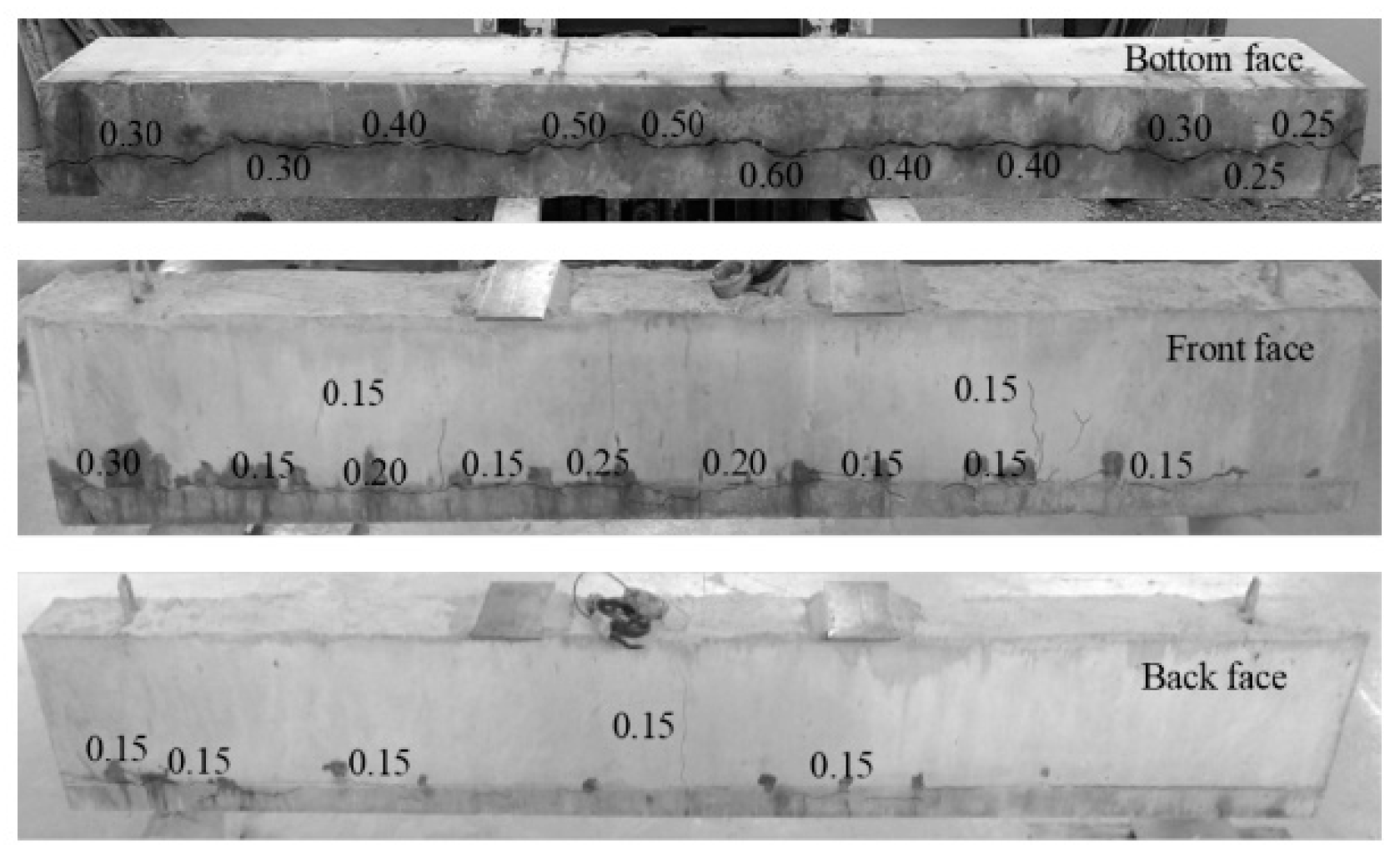
The cracking maps of corroded beams were drawn, and the crack widths were measured at the end of each corrosion phase by macroscopic visual inspection including visual screening and crack width detector (crack width comparator). One longitudinal crack was formed in the tensile bottom face of all beams, running parallel to the middle tensile rebar (all beams had three bottom bars). Rust spots also formed along these cracks. Further, longitudinal corrosion cracks due to corrosion developed at the front and back faces of beams, at the level of the tensile reinforcement in a parallel direction. As corrosion progressed, longitudinal cracks increased their width. At the end of the fourth wet–dry cycle (total of 8 weeks), the maximum longitudinal crack width on the tensile bottom was equal to 0.60 mm, while at the front face, the maximum crack was 0.25 mm. Figure 2 presents the crack pattern of beam BC1 at the low corrosion level. The crack patterns for BC1-60 and BC1-75 were found to be similar at this level before serviceability loading.
Beams BC1-60 and BC1-75 were subjected to service loads. The flexural cracks due to loading were formed in a direction perpendicular to the neutral axis of beams, in the middle area. The maximum flexural crack width was 0.30 mm for beam BC1-60 and 0.40 mm for the beam subjected to a higher load BC1-75. Flexural-shear cracks also formed at shear spans, but were thinner in width at approximately 0.15 mm. Then, the two beams were subjected to further corrosion exposure, under similar conditions of accelerated process for a total of 16 weeks. At medium corrosion level, the longitudinal cracks due to corrosion increased their width, but no development of new cracks was observed. The maximum longitudinal crack width at the front face ranged between 0.30 mm to 0.40 mm (0.25 mm at the low corrosion level) and was measured equal to 0.80 mm at the tensile bottom (0.60 mm at the low corrosion level) for both beams.
Next, the beams were subjected to a vertical load at the serviceability level. More flexural cracks formed in the middle area. For beam BC2-60, the maximum flexural crack width remained as 0.30 mm and some more cracks were created of 0.20 mm width. The flexural crack width increased for beam BC2-75 between 0.45–0.50 mm. The longitudinal cracks due to corrosion increased their width in the front face for both beams during loading. Specifically, crack width on the front face of beam BC2-60 that measured equal to 0.30 mm during the exposure at medium corrosion level, increased to 0.50 mm. When loading beam BC2-75 at service load, the longitudinal crack on the front face of 0.40 mm width as measured during the corrosion exposure, increased to 0.80 mm. At the third and last level of corrosion (high corrosion), the two beams were subjected to further corrosion exposure, under similar conditions of accelerated process, for a total of 24 weeks. Longitudinal crack widths increased significantly for both beams. The maximum width as measured along the longitudinal crack in the front face of both beams was 0.80 mm, while in the tensile bottom, the maximum crack increased to 1.25 mm width for both beams. Finally, they were subjected to service loads. Beam BC3-60 increased the flexural cracks in the middle area up to 0.35 mm, and also the flexural-shear cracks were greater at approximately 0.30 mm. Beam BC3-75, that was subjected to a higher load, greatly increased the middle flexural cracks between 0.50–1.50 mm and the maximum flexural-shear crack was measured equal to 0.50 mm. When loading beam BC3-60 at service load, the width of some longitudinal cracks on the front face were increased by approximately 0.10 mm compared to these measured during the corrosion exposure at high corrosion, but the maximum was still measured equal to 0.80 mm. As for beam BC3-75, when subjected to service load, some longitudinal cracks due to corrosion on the front face were further opened around 0.20–0.30 mm and the maximum was measured equal to 0.90 mm. Figure 3a,b shows the crack pattern of both beams during the last loading at high corrosion level. Figure 3c presents the tensile bottom side of BC3-75 after being subjected to last loading and before the removal of the damaged concrete cover. The longitudinal crack parallel to the middle reinforcement at the bottom side greatly increased for BC3-75, which indicates that during loading the crack due to corrosion was significantly affected. Particularly, a longitudinal crack width of 1.25 mm increased over 2.00 mm, while other longitudinal cracks of 0.60–0.80 mm opened more than 1.50 mm at the tensile bottom of BC3-75. For beam BC3-60, the maximum crack width at the bottom soffit was measured equal to 1.50 mm, while some other longitudinal cracks opened more from 0.60 mm to 0.80–0.90 mm as measured after loading. No spalling of concrete was observed after the corrosion exposure.
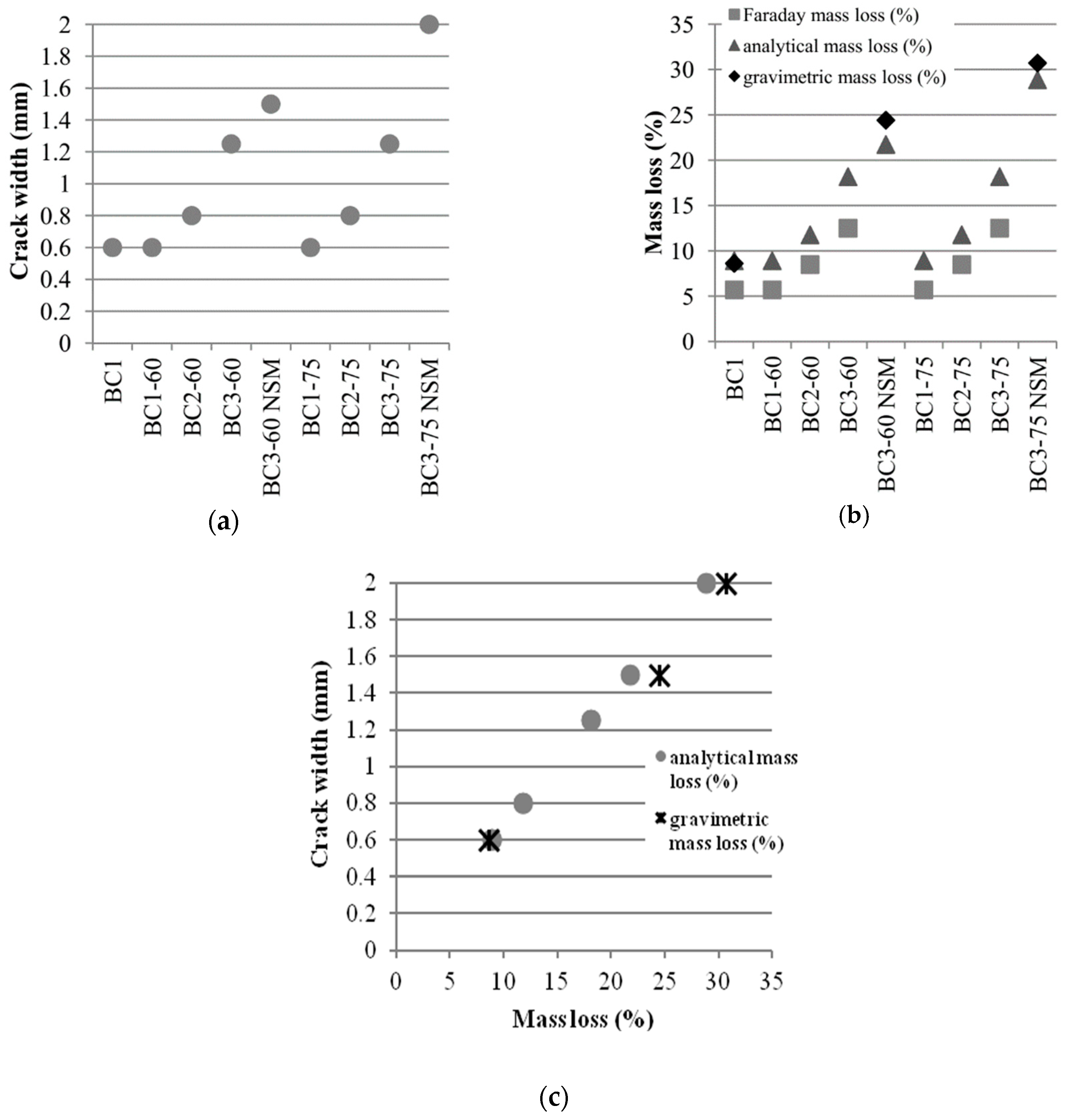
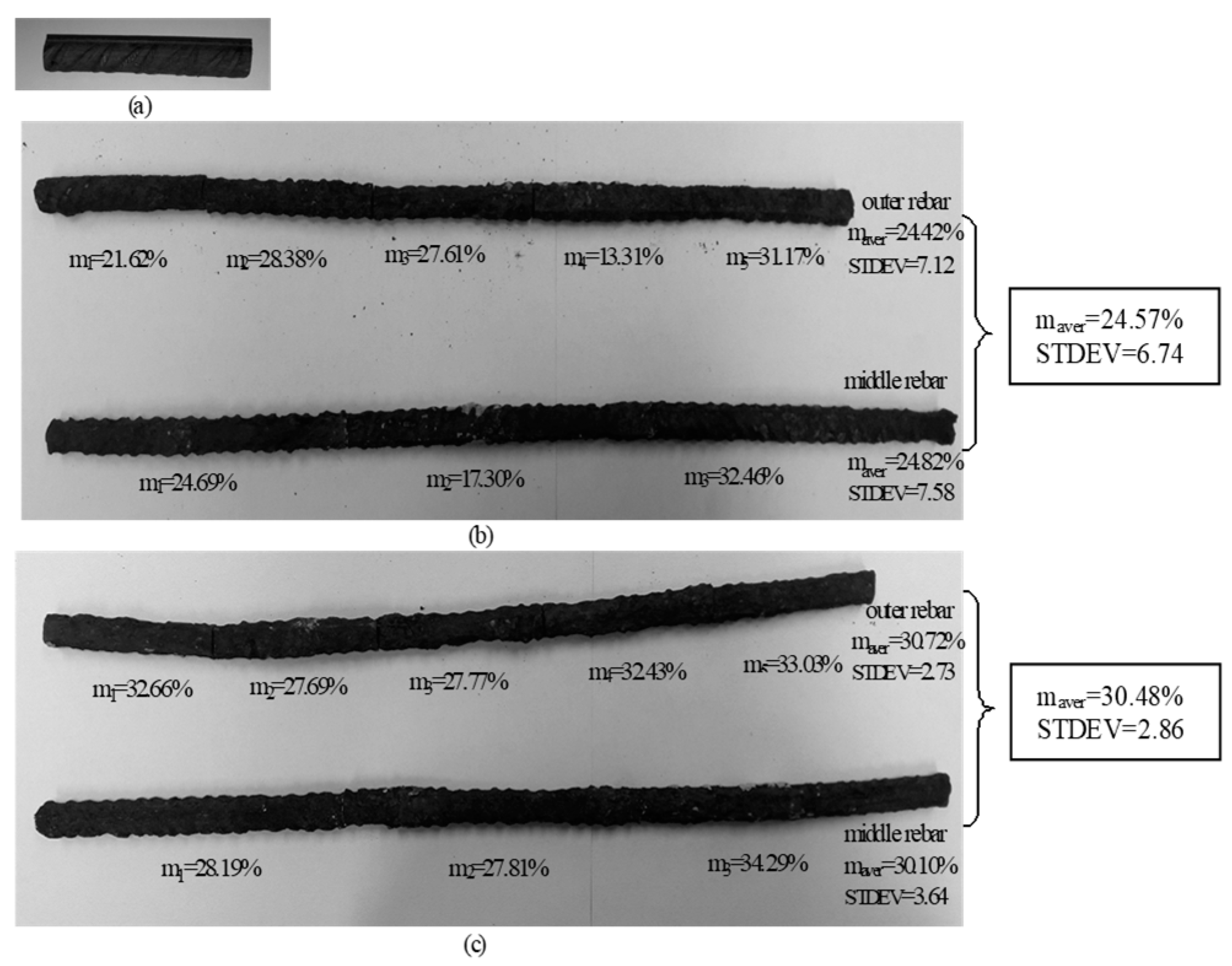
Corroded tensile rebars were revealed after testing beams BC1, BC3-60 NSM and BC3-75 NSM. Rather uniform corrosion was noticed all along the length. Some pitting in a few parts was evidenced, associated with the higher oxygen and moisture permeability in the concrete through the flexural cracks formed at service loading. Coupons of tensile reinforcement were extracted from the midspan region of the beams and were cleaned of rust according to ASTM G1-90 standard [48]. The corroded steel coupons were weighed, embedded in the proper solution, washed out with clean water, and weighed once again. The average mass loss of five corroded steel coupons of 80-mm length extracted from the outer rebar after testing was measured equal to mgrav = 8.62% for beam BC1, for BC3-60 NSM mgrav = 24.42% and for BC3-75 NSM mgrav = 30.72%. The average mass loss of three corroded steel coupons of 150 mm length extracted from the middle rebar after testing measured quite similar to the outer coupons, equal to mgrav = 24.82% for BC3-60 NSM and for BC3-75 NSM mgrav = 30.10%. An analytical model is utilized herein to estimate indirectly the residual average structural section area of uniformly corroded steel bar by steel mass loss (see Reference [43] for more details) based on the measured width of corrosion-induced cracks. The steel mass loss analytical model is a function of cover depth, bar diameter, and mechanical properties of concrete. The model includes relationships for the steel mass loss during the first phase of rust formulation (filling the porous zone) as well as during the phase that the radial pressure exceeds the concrete strength and causes cover cracking. In Triantafyllou et al. [43], it is proposed that after visible concrete cracking, the surrounding concrete area preserves a similar flexibility and rate of volume change because of rust. The analytical model predicts a steel mass loss equal to manal = 8.92%, for a measured longitudinal crack width of 0.60 mm on the tensile bottom, while the average mass loss of corroded steel coupons for beam BC1 after testing was measured equal to mgrav = 8.62%. The estimation of steel mass loss using Faraday’s law was lower, equal to mFarad = 5.7% (see also the study by Reference [49]). Similarly, for the remaining beams before being subjected to service loads, the analytical steel mass loss was manal = 8.92% (as the maximum longitudinal corrosion crack had a width of 0.60 mm). Figure 4 shows the relevant results for each beam.
Figure 4c clearly shows the linear relation between the longitudinal maximum crack width and the gravimetric mass loss, executed after the final cycle of severe corrosion (previous SLS loading included). The deviation between the crack width-analytical mass loss curve and crack width-gravimetric mass loss may provide a measure of the effect of the SLS loading cycles on the mass loss. It seems that the mass loss may be higher than what is expected for unloaded beams.
The proposed analytical model assuming a longitudinal crack width of 0.80 mm due to corrosion on the bottom side and before loading for beams BC2-60 and BC2-75, results in a steel mass loss equal to manal = 11.77%. The corresponding estimation of steel mass loss using Faraday’s law was lower and equal to mFarad = 8.5%. Assuming a longitudinal crack width equal to 1.25 mm due to corrosion and before loading beams BC3-60 and BC3-75, the analytical steel mass loss was estimated to be equal to manal = 18.18%, while the corresponding estimation using Faraday’s law was lower equal to mFarad = 12%.
After being tested to service loads, beam BC3-75 had a maximum longitudinal crack width equal to w = 2.00 mm, so the proposed analytical model predicts a mass loss equal to manal = 28.86%, while the average gravimetric mass loss of corroded steel coupons was measured equal mgrav = 30.72% for the outer rebar and mgrav = 30.10% for the middle rebar for BC3-75 NSM after testing to failure. Assuming a longitudinal crack width equal to w = 1.50 mm for beam BC3-60 after loading, the proposed analytical model predicts a mass loss equal to manal = 21.74%, while the average gravimetric mass loss of corroded steel coupons was measured equal to mgrav = 24.42% for the outer rebar and mgrav = 24.82% for the middle rebar for BC3-60 NSM after testing to failure. Figure 5 shows the corroded steel coupons after cleaning from corrosion products. Pitting corrosion has been noticed as the mass loss varied along the length of both outer and middle rebars.

3.2. Structural Performance of Non Corroded (B1) and Corroded (BC1) Beams

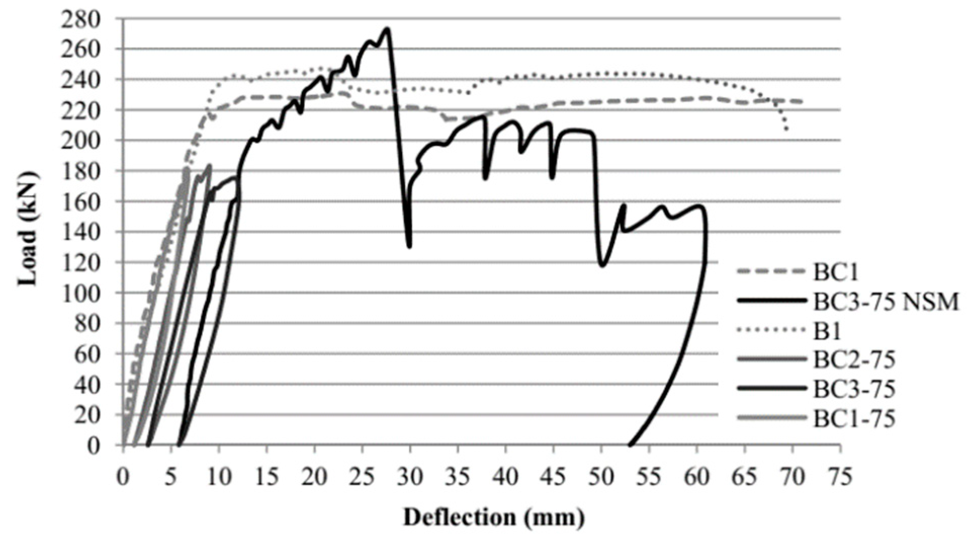
The non-corroded beam B1 and the corroded beam BC1 subjected to a small corrosion level were tested to failure. The maximum load of BC1 was approximately 6.9% (load of 231 kN) lower than that of the reference beam (248 kN). Figure 6 and Figure 7 depict the load-deflection curves of all specimens. Both beams exhibited flexural modes of failure by yielding of the tensile steel reinforcement and then crushing of the concrete in the compression zone. As the imposed deflections increased, a part of the corroded concrete cover in the middle flexural zone of BC1 detached. The corroded beam had a 70.8 mm deflection at failure, while the uncorroded beam failed at a lower deflection of 69.4 mm. Therefore, a slight increase in the deflection capacity of 2% for the corroded beam was noted.

3.3. Structural Performance of Corroded Beams (BC1,2,3-60, BC1,2,3-75) under Service Loads

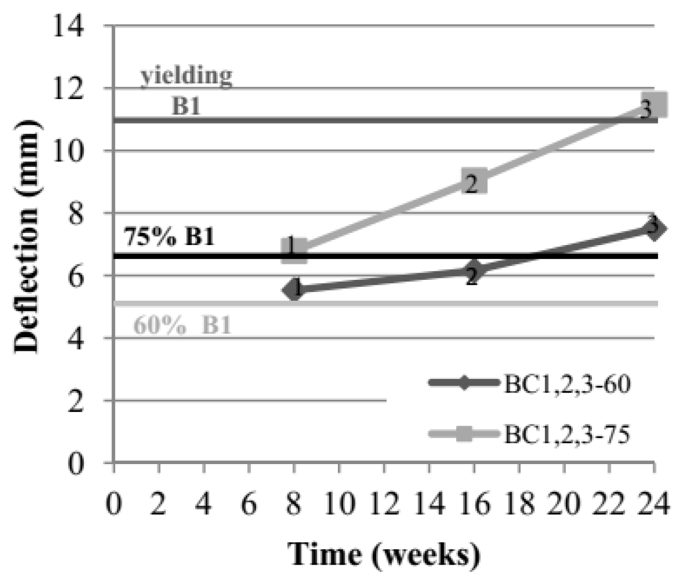
Corrosion of reinforcing steel can significantly influence the serviceability of concrete structures through strength or stiffness loss. Stiffness loss of RC beams may cause excessive deflection. Both beams present monotonically increased deflection over time due to steel corrosion effects (Figure 8, Table 1). Beam BC1-60 that was subjected to 60% of the yield load of non-corroded beam presented a deflection of 5.53 mm during the first loading for a low corrosion level (measured around ml = 8.6%). During the second loading (BC2-60) and a mass loss of tensile reinforcement of around 11.8% (as predicted by Reference [43]’s model), the deflection was measured equal to 6.16 mm (11.3% increase) and during the last loading (BC3-60) for a high corrosion level (measured around ml = 24.5%) the deflection was equal to 7.5 mm (35.6% increase compared to the first loading).
Beam BC1-75, that was subjected to 75% of the yield load of non-corroded beam, presented a deflection of 6.79 mm during the first loading for a low corrosion level (measured around ml = 8.6%). During the second loading (BC2-75) and a mass loss of steel of 11.8% (as predicted by Reference [43]), the deflection was measured equal to 9.04 mm (33.1% increase). During the last loading (BC3-75) for a high corrosion level (measured around ml = 30.5%), the deflection was equal to 11.47 mm (68.9% increase compared to the first loading). In beam BC3-75, with the higher load and severe corrosion, the reinforcing steel yielded at the last loading procedure before it reached the 75% yielding load of non-corroded beam. This is attributed to a significant cross section reduction caused by the extensive corrosion and loss of bond between concrete cover and steel reinforcement, as was observed after the removal of the damaged concrete cover (Figure 3d). Beam BC3-75 was intensively cracked over the entire length, and tensile reinforcement was severely corroded. The diameter of the rebars was measured with a Vernier Caliper around Ø ≈ 12 mm (on average) and almost all the stirrups had been totally cut due to corrosion (Figure 3d). Beam BC3-60 presented a lower damage (Figure 3e), as the loss of bond between concrete cover and steel was not so intense, only two of the stirrups had been cut due to corrosion and their diameter was measured equal to Øw ≈ 4 mm with the Vernier Caliper, while the corresponding measurement of the tensile rebars was equal to Ø ≈ 13 mm. Beam BC3-75 (higher loading level) exhibited a higher increase in deflection for higher corrosion. The wider cracks might increase the permeability of concrete to corrosive agents but could provide some ways out for the corrosion products generated by further corrosion. It should be considered that the tensile bars were not under serviceability level stress during accelerated corrosion phases.
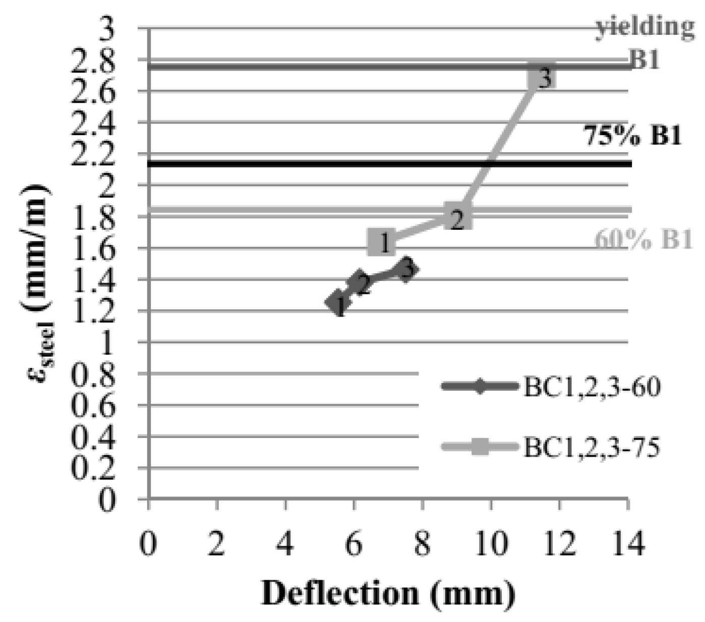
The strains of the corroded tensile reinforcement were also recorded during each loading phase (Figure 9). Similar to the variation of the deflections, steel strains also increased during the corrosion-loading process. For beam BC2-60, the midspan strains of steel were 10.4% higher at the second loading phase (εsteel = 1.38‰) compared to the first (BC1-60 εsteel = 1.25‰) and 5.8% higher (BC3-60 εsteel = 1.46‰) at the third loading compared to the second one. For the second beam, the midspan strains of steel were increased between the first (BC1-75 εsteel = 1.64‰) and the second (BC2-75 εsteel = 1.81‰) loading phase at approximately 10.4% and at the third loading (BC3-75 εsteel = 2.71‰) to a level equal to the yielding strain of the non-corroded beam (49.7% increase compared to the second loading phase). This indicates that an increase of the service load by 15% (at 75% of the yield load) leads to yielding of the beam at high corrosion levels. Given the results of the experimental campaign, two different cases are examined at serviceability limit states that are very crucial for structural health monitoring and timely and efficient retrofit as it will be shown below, the one before reaching yielding strain of corroded steel and the one beyond steel yielding.

3.4. Structural Performance of Patch-Repaired and NSM Strengthened Corroded Beams (BC3-60 NSM, BC3-75 NSM)

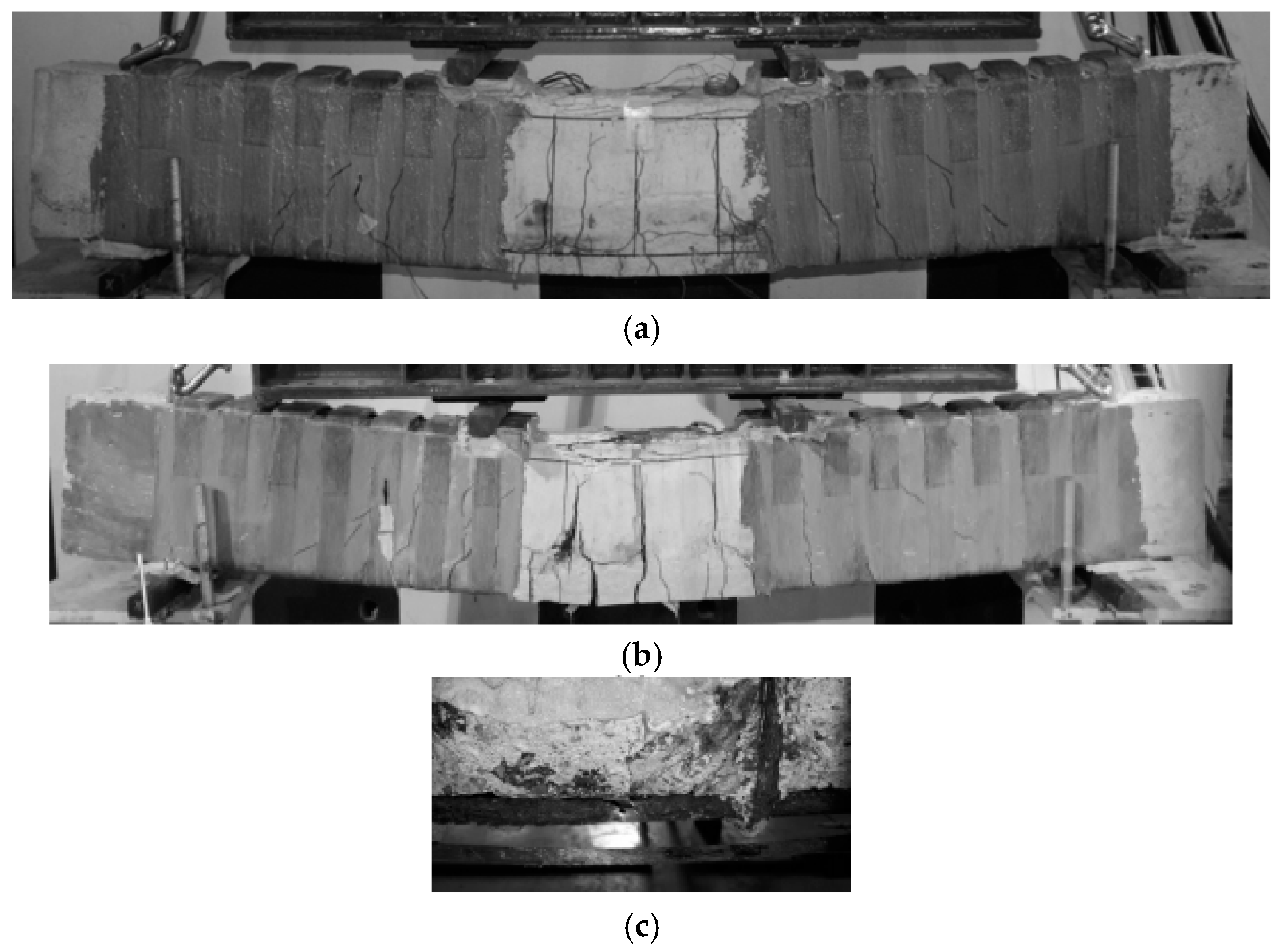
The main results from the experimental program are listed in Table 2 in terms of cracking load, yielding load, and ultimate load, as well as their corresponding deflections. Beam BC3-60 NSM that was subjected to 60% service load even after repair with the NSM strips, presented a cracking load of 10.6% lower than non-corroded beam. The yielding load was 25.2% lower than that of non-corroded beam B1 due to the steel cross-section reduction resulting from the induced corrosion. It can be seen from Figure 6 that the patch repair and NSM strengthening could obviously improve the ultimate capacity of BC3-60 NSM, where the maximum load increased by 3.3% (256 kN at 20.4 mm) compared to the reference beam B1. Longitudinal cracks at the interface of the old concrete substrate and the patch repair concrete were observed only after yielding of steel in tension. The width of these cracks was equal to 0.20 mm. At maximum load, these cracks at the interface opened more and their width varied between 0.40–0.60 mm in the middle flexural region. Flexural cracks further opened and increased their width, and the maximum was measured equal to 1.20 mm. At shear spans, cracks were fewer with widths between 0.30–0.40 mm. When the beam reached 24 mm deflection, the load decreased to 174 kN and a loud sound was heard. Similar sounds were heard when the load dropped to approximately 180–190 kN (190 kN at 36.1 mm, 184 kN at 46.1 mm and 190 kN at 54.9 mm). These sounds were probably caused by slipping of the NSM laminates. As loading progressed, BC3-60 NSM continued to maintain the load at high levels at greater deflections. The residual post debonding bearing load was limited to 222 kN at 22.3 mm deflection and remained around 180–240 kN up to 54.1 mm deflection. Debonding at the epoxy-CFRP strips interface and localized splitting of the epoxy cover were detected after failure, as well as intermediate debonding between the old and new concrete substrate and finally concrete crushing (Figure 10a). The CFRP wraps had an influence in delaying debonding. At maximum load, the CFRP strain was measured equal to 1.03%, which corresponds to the 0.61εfu of the ultimate strain of the NSM strip (Figure 11). This value agrees well with the debonding strains according to ACI 440.2R-08 [50] equal to 1.12% (0.66εfu) for the high mortar strength.
For beam BC3-75 NSM that was subjected to 75% service load even after repair with the NSM strips, the first flexural cracks appeared at a load of 38.5 kN, 15.2% lower than the non-corroded beam B1. The yielding load was equal to 201 kN, 17.4% lower because of the steel cross-section loss due to corrosion. The ultimate load at debonding was 272 kN at 27.7 mm deflection (Figure 7). This is a 9.8% higher load compared to the non-corroded beam B1 and 6.3% higher compared to the BC3-60 NSM strengthened beam with the lower service load but with equivalent axial rigidity FRP reinforcement. In spite of large corrosion cracks and flexural cracks in the middle area due to loading, the ultimate capacity of beam BC3-75 NSM was still higher than the corresponding capacity of the non-corroded beam. The higher bearing load of the BC3-75 NSM beam might be attributed to the higher level of damage of concrete around the corroded bars and stirrups that led to more extensive replacement of old concrete by the high performance patch material. For the same reason, the bond at the old concrete-patch interface is expected to be higher. Further, the cut stirrups in several places and the already yielded steel led the localization of the severe damage at the one side of the beam and the shear CFRP strap reinforcements to be highly activated. All these local effects might have resulted in the higher contribution of the patch mortar all over the span that resulted in a higher contribution of the NSM CFRP. At maximum load, the flexural cracks ranged between 0.80–1.50 mm, while the maximum crack width at shear spans was measured equal to 0.90 mm. After sudden bond loss of NSM strengthening, the residual post debonding bearing load was limited to 134 kN at 29.8 mm deflection (loud sound was heard-possible slipping of NSM laminates) and then increased to 188 kN at 30.8 mm deflection. Beam BC3-75 NSM exhibited debonding in the form of concrete cover separation, after yielding of the tensile steel bars, intermediate debonding between the old and the new concrete substrate and finally concrete crushing. Debonding at the epoxy-CFRP strips interface and localized splitting of the epoxy cover were detected after failure (Figure 10b). Failure also included rupture of a corroded tensile rebar in the middle region at deep corrosion pits (Figure 10c). The rupture of the tensile rebar occurred at a load of 205 kN and deflection of 49.9 mm. Another loud sound was heard at 52.3 mm deflection where the load dropped to 141 kN. The failure load at extensive concrete crushing was 156 kN at 60.6 mm deflection. At this time, a tiny longitudinal crack was formed at the interface between the old and repaired concrete of less than 0.15 mm width. The strain gauges of the NSM plates stopped recording at a value of 0.7% at load 220 kN, before it even reached the maximum load (Figure 11). Beam BC3-75 NSM, with higher steel corrosion, cut stirrups and further extended concrete cover damage, exhibited higher bearing load after retrofit at slightly higher deflection levels than BC3-60 NSM. Yet, it presented a lower residual bearing load after first debonding failure and finally rupture of the tensile steel rebar.
The steel–concrete bond loss in the tensile reinforcement due to corrosion is the main factor that affects the stiffness of corroded beams because of the resulting loss of the concrete tension stiffening effect. During the propagation phase of corrosion which corresponded to localized corrosion, the reduction in stiffness resulted from the steel–concrete bond loss induced by corrosion crack propagation along the tensile reinforcement. When corrosion cracks increased their width, the reduction in stiffness was due to the uniform loss of the steel cross-section. The stiffness of beams was calculated based on the level of service loads and the loading arrangements:
E I = M 24 Δ ( 3 l 2 4 l s 2 )
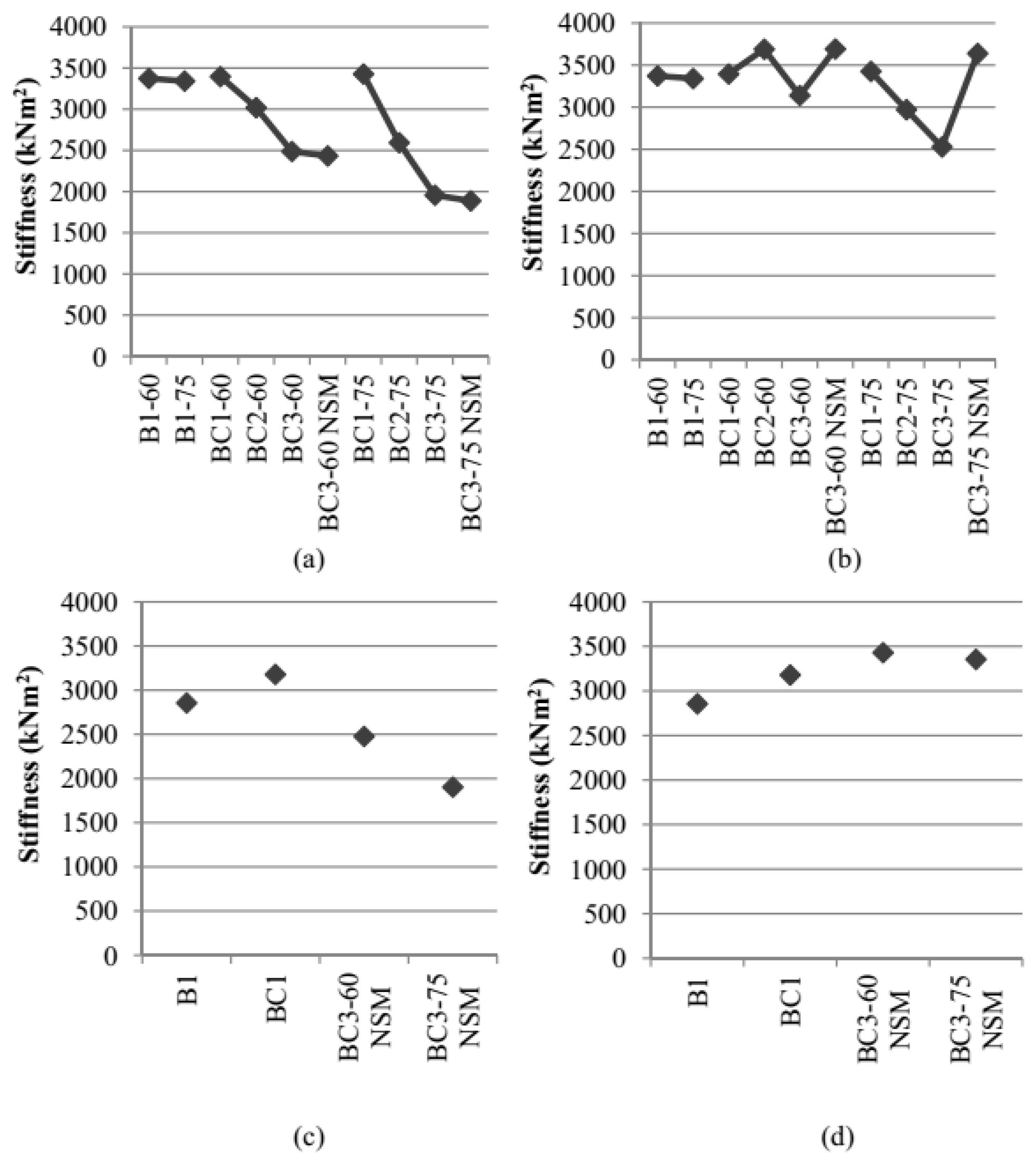
where EI is the stiffness of beams (kN*m2), M is the external applied moment, Δ is the measured deflection, l = 1.92 m is the span of the beam, and ls = 0.66 m is the shear span. Figure 12 indicates that flexural stiffness derived from beams’ deflections calculated as (kN*m2) was decreased for both beams, with an increasing rate for the beam with the higher service load. Strengthening with NSM laminates seems to recover a part of the total stiffness of the beam because of the bond between the concrete and NSM laminate.

4. Conclusions

This paper investigates the mechanical behaviour of RC beams subjected to two different SLS loads and to three subsequent raising corrosion levels as well as their efficient retrofit. Steel corrosion is an urgent issue internationally, leading to several collapses of structures [51]. The study underlines the necessity for the replacement of the cracked concrete substrate with a polymer-modified cementitious mortar of high strength before applying FRP reinforcement, in order to avoid the separation of the concrete cover due to corrosion-induced cracks (as found by References [41,42]). The following conclusions can be drawn based on the experimental results of this study:
  • Beams BC1-60 and BC1-75 that were subjected to 60% and 75% of yield load of non-corroded beam B1 correspondingly presented a similar mass loss of steel due to the corrosion of measured levels up to 12% mass loss (revealing similar crack widths).
  • For the beam loaded under 75% of yield load, further corrosion resulted in higher mass loss (around 24% higher mass loss, at a mass loss level of around 30% for BC3-75 compared to around 25% for BC3-60) as it revealed higher crack widths.
  • Beams BC3-60 and BC3-75 presented 35.6% and 68.9% higher deflection (almost double) for the high corrosion level compared to their first loading, respectively. Deflection of BC3-75 surpassed deflection at steel yielding.
  • Strengthening of the corroded beams with two NSM CFRP strips, having identical FRP reinforcement but under different service loads, resulted in different structural performances and failure modes. The failure mode of both corroded strengthened beams is mainly characterized by debonding in the form of concrete cover separation, as well as by debonding at the epoxy-CFRP strips interface. The new concrete cover of high strength allowed for further utilization of the NSM material. The strengthened corroded beam subjected to 60% service load had no cut steel stirrups at the old concrete-patch interface, a lower extent of damaged concrete cover, and no steel yielding. The strengthened corroded beam subjected to 75% service load had already entered steel yielding and had extensively corroded and cut stirrups. Beam BC3-75NSM revealed significant load loss after NSM debonding, and at higher deflections, the load remained lower than that of the non-corroded beam.
  • The structural performance of both retrofitted beams was as expected according to existing design recommendations or better up to CFRP NSM debonding. Patch repair and FRP strengthening can efficiently restore the capacity of corroded concrete beams. The residual bearing load after CFRP NSM debonding depends on the different localization of damages throughout loading in beams with different mass loss of steel (bars and stirrups) due to corrosion. Even in the case of tensile steel bars yielding, the proposed retrofit was successful. Yet, localization of damage and pitting corrosion should be thoroughly investigated in any case as it can significantly reduce the tensile deformability of steel. The current study may contribute to the identification of the characteristic serviceability limit state for corroded beams (under structural health monitoring) in order to undertake successful retrofit actions or replace them.
  • The model by Reference [43] can provide a satisfactory indirect prediction of the steel mass loss at each corrosion phase based on the measured corrosion-induced crack width. The SLS loading cycles seem to further increase the mass loss of steel.
  • Further elaborations should be focused on the crack development and potential steel–concrete bond loss at serviceability limit states due to steel corrosion.

Author Contributions

G.T., T.R. and A.K. conceived and designed the experiments, performed the experiments, analyzed the data and wrote the paper.

Funding

This research was supported by the IKY (Greek State Scholarships Foundation) RESEARCH PROJECTS FOR EXCELLENCE IKY/SIEMENS. The authors wish to acknowledge the support provided by Sika Hellas for providing the CFRP reinforcement, filling materials (adhesive epoxy), materials for corrosion protection and cement for the repair technique.

Conflicts of Interest

The authors declare no conflict of interest.

References

  1. Mohammed, T.; Otsuki, N.; Hisada, M.; Shibata, T. Effect of Crack Width and Bar Types on Corrosion of Steel in Concrete. J. Mater. Civ. Eng. 2001, 13, 194–201. [Google Scholar] [CrossRef]
  2. Bossio, A.; Lignola, G.P.; Fabbrocino, F.; Monetta, T.; Prota, A.; Bellucci, F.; Manfredi, G. Nondestructive assessment of corrosion of reinforcement bars through surface concrete cracks. Struct. Concr. 2017, 18, 104–117. [Google Scholar] [CrossRef]
  3. Goksu, C.; Ilki, A. Seismic Behavior of Reinforced Concrete Columns with Corroded Deformed Reinforcing Bars. ACI Struct. J. 2016, 113, 1–12. [Google Scholar] [CrossRef]
  4. Bossio, A.; Fabbrocino, F.; Monetta, T.; Lignola, G.P.; Prota, A.; Manfredi, G.; Bellucci, F. Corrosion effects on seismic capacity of reinforced concrete structures. Corros. Rev. 2019, 37, 45–56. [Google Scholar] [CrossRef]
  5. Alonso, C.; Andrade, C.; Rodriguez, J.; Diez, J. Factors controlling cracking of concrete affected by reinforcement corrosion. Mater. Struct. 1998, 31, 435–441. [Google Scholar] [CrossRef]
  6. Ballim, Y.; Reid, J.C. Reinforcement corrosion and the deflection of RC beams-an experimental critique of current test methods. Cem. Concr. Compos. 2003, 25, 625–632. [Google Scholar] [CrossRef]
  7. Yoon, S.; Wang, K.; Weiss, W.J.; Shah, S.P. Interaction between loading, corrosion and serviceability of reinforced concrete. ACI Mater. J. 2000, 97, 637–644. [Google Scholar]
  8. El Maaddawy, T.; Soudki, K.; Topper, T. Long-Term Performance of Corrosion-Damaged Reinforced Concrete Beams. ACI Struct. J. 2005, 102, 649–656. [Google Scholar]
  9. Ababneh, A.; Sheban, M. Impact of mechanical loading on the corrosion of steel reinforcement in concrete structures. Mater. Struct. 2011, 44, 1123–1137. [Google Scholar] [CrossRef]
  10. Hariche, L.; Ballim, Y.; Bouhicha, M.; Kenai, S. Effects of reinforcement configuration and sustained load on the behaviour of reinforced concrete beams affected by reinforcing steel corrosion. Cem. Concr. Compos. 2012, 34, 1202–1209. [Google Scholar] [CrossRef]
  11. Liu, Y.; Jiang, N.; Deng, Y.; Ma, Y.; Zhang, H.; Li, M. Flexural experiment and stiffness investigation of reinforced concrete beam under chloride penetration and sustained loading. Constr. Build. Mater. 2016, 117, 302–310. [Google Scholar] [CrossRef] [Green Version]
  12. Malumbela, G.; Moyo, P.; Alexander, M. Behaviour of RC beams under sustained service loads. Constr. Build. Mater. 2009, 23, 3346–3351. [Google Scholar] [CrossRef]
  13. Malumbela, G.; Moyo, P.; Alexander, M. Longitudinal strains and stiffness of RC beams under load as measures of corrosion levels. Eng. Struct. 2012, 35, 215–227. [Google Scholar] [CrossRef]
  14. Torres-Acosta, A.; Fabela-Gallegos, M.; Munoz-Noval, A.; Vazquez-Vega, D.; Hernandez-Jimenez, T.; Martinez-Madrid, M. Influence of corrosion on the structural performance of reinforced concrete beams. Corrosion 2004, 60, 862–872. [Google Scholar] [CrossRef]
  15. Ting, S.; Nowak, A.S. Effect of reinforcing steel area loss on flexural behaviour of reinforced concrete beams. ACI Struct. J. 1991, 88, 309–314. [Google Scholar]
  16. Du, Y.; Cullen, M.; Li, C. Structural performance of RC beams under simultaneous loading and reinforcement corrosion. Constr. Build. Mater. 2013, 38, 472–481. [Google Scholar] [CrossRef]
  17. Dang, V.; Francois, R. Influence of long-term corrosion in chloride environment on mechanical behaviour of RC beam. Eng. Struct. 2013, 48, 558–568. [Google Scholar] [CrossRef]
  18. Francois, R.; Khan, I.; Dang, V. Impact of corrosion on mechanical properties of steel embedded in 27-year old corroded reinforced concrete beams. Mater. Struct. 2012, 46, 899–910. [Google Scholar] [CrossRef]
  19. Zhu, W.; Francois, R.; Coronelli, D.; Cleland, D. Effect of corrosion of reinforcement on the mechanical behaviour of highly corroded RC beams. Eng. Struct. 2013, 56, 544–554. [Google Scholar] [CrossRef]
  20. Yu, L.; Francois, R.; Dang, V.; L’Hostis, V.; Gagne, R. Structural performance of RC beams damaged by natural corrosion under sustained loading in a chloride environment. Eng. Struct. 2015, 96, 30–40. [Google Scholar] [CrossRef]
  21. Zhang, R.; Castel, A.; Francois, R. Serviceability limit state criteria based on steel-concrete bond loss for corroded reinforced concrete in chloride environment. Mater. Struct. 2009, 60, 1407–1421. [Google Scholar] [CrossRef]
  22. Jiang, C.; Wu, Y.; Dai, M. Degradation of steel-to-concrete bond due to corrosion. Constr. Build. Mater. 2018, 158, 1073–1080. [Google Scholar] [CrossRef]
  23. Hollaway, L.C.; Teng, J.G. Strengthening and Rehabilitation of Civil Infrastructures Using Fibre-Reinforced Polymer (FRP) Composites; Woodhead Publishing: Boca Raton, FL, USA, 2008. [Google Scholar]
  24. Rousakis, T. Retrofitting and Strengthening of Contemporary Structures: Materials Used. In Encyclopedia of Earthquake Engineering: Chapter; Beer, M., Patelli, E., Kougioumtzoglou, I., Au, I., Eds.; Springer: Berlin/Heidelberg, Germany, 2014; Volume 2013. [Google Scholar]
  25. Antonopoulos, C.P.; Triantafillou, T.C. Experimental Investigation of FRP-Strengthened RC beam-Column Joints. J. Compos. Constr. 2003, 7, 39–49. [Google Scholar] [CrossRef]
  26. Gao, P.; Gu, X.; Mosallam, A.S. Flexural behavior of preloaded reinforced concrete beams strengthened by prestressed CFRP laminates. Compos. Struct. 2016, 157, 33–50. [Google Scholar] [CrossRef] [Green Version]
  27. Rousakis, T.C.; Karabinis, A.I. Adequately FRP confined reinforced concrete columns under axial compressive monotonic or cyclic loading. Mater. Struct. 2012, 45, 957–975. [Google Scholar] [CrossRef]
  28. Bocciarelli, M.; Feo, C.; Nistico, N.; Pisani, M.; Poggi, C. Failure of RC beams strengthened in bending with unconventionally arranged CFRP laminates. Compos. Part B 2013, 54, 246–254. [Google Scholar] [CrossRef]
  29. Triantafyllou, G.G.; Rousakis, T.C.; Karabinis, A.I. Axially loaded reinforced concrete columns with a square section partially confined by light GFRP straps. J. Compos. Constr. 2014, 19, 04014035. [Google Scholar] [CrossRef]
  30. Charalambidi, B.; Rousakis, T.; Karabinis, A. Fatigue Behavior of Large-Scale Reinforced Concrete Beams Strengthened in Flexure with Fiber-Reinforced Polymer Laminates. J. Compos. Constr. 2016, 20, 04016035. [Google Scholar] [CrossRef]
  31. Rezazadeh, M.; Cholostiakow, S.; Kotynia, R.; Barros, J. Exploring new NSM reinforcements for the flexural strengthening of RC beams: Experimental and numerical research. Compos. Struct. 2016, 141, 132–145. [Google Scholar] [CrossRef] [Green Version]
  32. Ferrier, E.; Avril, S.; Hamelin, P.; Vautrin, A. Mechanical behavior of RC beams reinforced by externally bonded CFRP sheets. Mater. Struct. 2003, 36, 522–529. [Google Scholar] [CrossRef]
  33. Soudki, K.; El-Salakawy, E.; Craig, B. Behavior of CFRP strengthened Reinforced Concrete Beams in Corrosive Environment. J. Compos. Constr. 2007, 11, 291–298. [Google Scholar] [CrossRef]
  34. Badawi, M.; Soudki, K. Control of Corrosion-Induced Damage in Reinforced Concrete Beams Using Carbon Fiber-Reinforced Polymer Laminates. J. Compos. Constr. 2005, 9, 195–201. [Google Scholar] [CrossRef]
  35. El Maaddawy, T.; Soudki, K. Carbon-Fiber-Reinforced Polymer Repair to Extend Service Life of Corroded Reinforced Concrete Beams. J. Compos. Constr. 2005, 9, 187–194. [Google Scholar] [CrossRef]
  36. El Maaddawy, T.; Soudki, K.; Topper, T. Performance Evaluation of Carbon Fiber-Reinforced Polymer Repaired Beams Under Corrosive Environmental Conditions. ACI Struct. J. 2007, 104, 3–11. [Google Scholar]
  37. Ray, I.; Parish, G.; Davalos, J.; Chen, A. Effect on Concrete Substrate Repair Methods for Beams Aged by Accelerated Corrosion and Strengthened with CFRP. J. Aerosp. Eng. 2011, 24, 227–239. [Google Scholar] [CrossRef]
  38. Triantafyllou, G.G.; Rousakis, T.C.; Karabinis, A.I. Corroded RC beams patch repaired and strengthened in flexure with fiber-reinforced polymer laminates. Compos. Part B 2017, 112, 125–136. [Google Scholar] [CrossRef]
  39. Malumbela, G.; Alexander, M.; Moyo, P. Variation of steel loss and its effect on the ultimate flexural capacity of RC beams corroded and repaired under load. Constr. Build. Mater. 2010, 24, 1051–1059. [Google Scholar] [CrossRef]
  40. Malumbela, G.; Alexander, M.; Moyo, P. Serviceability of corrosion-affected RC beams after patch repairs and FRPs under load. Mater. Struct. 2011, 44, 331–349. [Google Scholar] [CrossRef]
  41. Kreit, A.; Al-Mahmoud, F.; Castel, A.; Francois, R. Repairing corroded RC beam with near-surface mounted CFRP rods. Mater. Struct. 2011, 44, 1205–1217. [Google Scholar] [CrossRef]
  42. Almassri, B.; Kreit, A.; Al-Mahmoud, F.; Francois, R. Mechanical behaviour of corroded RC beams strengthened by NSM CFRP rods. Compos. Part B 2014, 64, 97–107. [Google Scholar] [CrossRef]
  43. Triantafyllou, G.G.; Rousakis, T.C.; Karabinis, A.I. Analytical assessment of the bearing capacity of RC beams with corroded steel bars beyond concrete cover cracking. Compos. Part B 2017, 119, 132–140. [Google Scholar] [CrossRef]
  44. ASTM C39/C39M. Standard Test Method for Compressive Strength of Cylindrical Concrete Specimens; ASTM International: West Conshohocken PA, USA, 2015. [Google Scholar]
  45. ASTM C469/C469M. Standard Test Method for Static Modulus of Elasticity and Poisson’s Ratio of Concrete in Compression; ASTM International: West Conshohocken, PA, USA, 2014. [Google Scholar]
  46. ASTM C496/C496M. Standard Test Method for Splitting Tensile Strength of Cylindrical Concrete Specimens; ASTM International: West Conshohocken, PA, USA, 2011. [Google Scholar]
  47. ASTM C370-14. Standard Test Methods and Definitions for Mechanical Testing of Steel Products; ASTM International: West Conshohocken, PA, USA, 2014. [Google Scholar]
  48. ASTM G1-90. Standard Practice for Preparing, Cleaning and Evaluating Corrosion Test Specimens; ASTM International: West Conshohocken, PA, USA, 2002; p. 8. [Google Scholar]
  49. Xie, J.; Hu, R. Experimental study on rehabilitation of corrosion-damaged reinforced concrete beams with carbon fiber reinforced polymer. Constr. Build. Mater. 2012, 38, 708–716. [Google Scholar] [CrossRef]
  50. American Concrete Institute (ACI). Guide for the Design and Construction of Externally Bonded FRP Systems for Strengthening Concrete Structures; ACI 440.2R-08; CRC Press: Farmington Hills, MI, USA, 2008. [Google Scholar]
  51. Colajanni, P.; Recupero, A.; Ricciardi, G.; Spinella, N. Failure by corrosion in PC bridges: A case history of a viaduct in Italy. Int. J. Struct. Integr. 2016, 7, 181–193. [Google Scholar] [CrossRef]
Figure 1. Specimen test setup and reinforcement configuration.
Buildings 09 00067 g001
Figure 2. Crack pattern of corroded beam BC1 after the end of the accelerated corrosion.
Buildings 09 00067 g002
Figure 3. Crack pattern of BC3-60 (a) and BC3-75 (b) at front faces and of BC3-75 (c) at tensile bottom during the last loading at high corrosion level. Beams BC3-75 (d) and BC3-60 (e) after removal of damaged concrete.
Buildings 09 00067 g003
Figure 4. Crack width (a) and mass loss (b) for beams after each corrosion-loading cycle and their interrelation for analytical and gravimetric mass loss (c).
Buildings 09 00067 g004
Figure 5. Steel coupons of the middle area for reference beam B1 (a) and for beams BC3-60NSM (b) and BC3-75NSM (c) after removal of corrosion products.
Buildings 09 00067 g005
Figure 6. Load-Deflection curves of beams B1, BC1 and BC1,2,3-60 and BC3-60 NSM.
Buildings 09 00067 g006
Figure 7. Load-Deflection curves of beams B1, BC1 and BC1,2,3-75 and BC3-75 NSM.
Buildings 09 00067 g007
Figure 8. Deflection versus Corrosion Time for beams BC1,2,3-60 and BC1,2,3-75 at each cycle.
Buildings 09 00067 g008
Figure 9. Deflection versus Strain of tensile reinforcement for beams BC1,2,3-60 and BC1,2,3-75 at each cycle.
Buildings 09 00067 g009
Figure 10. BC3-60 NSM beam after failure (a). BC3-75 NSM after failure (b) and rupture of a corroded tensile steel rebar at middle (c).
Buildings 09 00067 g010
Figure 11. Load Strain of NSM CFRP strips curves of beams BC3-60NSM and BC3-75NSM.
Buildings 09 00067 g011
Figure 12. Variation of Stiffness of tested beams at the level of service loads for total deflections (a), at the level of service loads for initial deflections (b) at each cycle, at the level of yielding loads for total deflections (c), and at the yielding for initial deflections (d).
Buildings 09 00067 g012
Table 1. Total deflections of tested beams.
BeamsBC1-60BC2-60BC3-60BC1-75BC2-75BC3-75
δ (mm)5.536.167.56.799.0411.47
Table 2. Test results of present study.
BeamsAt Concrete CrackingAt Steel YieldingAt Maximum LoadAt Ultimate Load
Pcr (kN)δcr (mm)Py (kN)δy (mm)Pmax (kN)δPmax (mm)Pu (kN)δu (mm)
B145.41.124310.924819.920569.4
BC1621.42188.823123.222570.8
BC3-60 NSM40.63.7 (1.1) 11829.4 (6.8)25620.4 (17.8)25620.4 (17.8)
BC3-75 NSM38.56.8 (1.0)20113.5 (7.7)27227.7 (21.9)27227.7 (21.9)
1 In parenthesis, the net deflections at each cycle of loading.