Article

Multi-Variable Multi-Objective Optimization Analysis of Super-Tall Building Structures Based on a Genetic Algorithm

1
School of Civil Engineering, Chongqing University, Chongqing 400045, China
2
State Key Laboratory of Safety and Resilience of Civil Engineering in Mountain Area, Chongqing 400045, China
*
Author to whom correspondence should be addressed.
Buildings 2026, 16(7), 1324; https://doi.org/10.3390/buildings16071324
Submission received: 26 January 2026 / Revised: 20 March 2026 / Accepted: 24 March 2026 / Published: 26 March 2026
(This article belongs to the Section Building Structures)

Abstract

Balancing structural safety and economic efficiency in super-tall building design remains a formidable challenge. To address this issue, this study proposes a genetic-algorithm-based multi-variable, multi-objective optimization method. The design variables include the member sizes and vertical layout positions of outrigger and belt trusses, as well as the cross-sectional dimensions of mega-columns. Total structural weight and maximum inter-story drift ratio are adopted as objective functions, while code-specified constraints, such as shear-weight ratio, stiffness-weight ratio, and axial compression ratio, are incorporated to formulate the fitness evaluation for optimization. Taking a 300 m baseline structure designed for 6-degree seismic intensity and equipped with two outrigger trusses and three belt trusses as an example, single-variable sensitivity analyses are first performed. The results show that optimizing any single parameter can yield certain local improvements, yet it cannot overcome the weight–deformation trade-off induced by strong variable coupling. By selecting representative feasible solutions from the multi-variable solution set that match the “optimal” values identified by single-variable optimization as benchmarks, the multi-variable optimum reduces the total structural weight by approximately 6.5–18.4% relative to these representative designs. Moreover, optimal layout strategies of outrigger and belt trusses are investigated for two typical building heights (200 m and 300 m) and two seismic intensity levels associated with design ground motions having a 10% exceedance probability in 50 years, namely 6-degree (0.05 g) and 8-degree (0.20 g). Finally, the proposed method is validated through a case study of a super-tall financial center in Chongqing, where the total structural weight is reduced by 12.3% after optimization while the inter-story drift ratio still satisfies relevant code requirements. The results demonstrate that the proposed framework can generate competitive feasible solutions and provide a systematic means to achieve a balanced trade-off between structural safety and economic efficiency for outrigger–belt-truss super-tall buildings.

1. Introduction

In recent years, super-tall buildings in China have widely adopted exterior frame–core tube systems strengthened by outrigger and belt truss stories, in order to achieve sufficient lateral stiffness while maintaining relatively small column cross sections. However, there is a strong coupling effect among the vertical positions and stiffnesses of the outrigger and belt trusses and the cross-sectional dimensions of the mega-columns. Different combinations of these parameters simultaneously affect the lateral displacement, internal force transfer paths, and material consumption of the structure, posing significant challenges to the simultaneous optimization of structural safety and economic efficiency.
Most existing studies focus on the optimization of a single component or a single parameter, such as determining only the optimal elevation of the outriggers or adjusting only the cross sections of the exterior frame columns. These approaches fail to integrate different types of design variables within a unified framework, and the resulting schemes still require substantial manual modifications in practical engineering applications. To overcome these limitations, this paper developed a genetic-algorithm-based multi-variable, multi-objective optimization framework. The vertical positions and sizes of the outrigger and belt trusses, together with the cross-sectional dimensions of the mega-columns, are simultaneously selected as design variables. The total structural weight and the maximum inter-story drift ratio are adopted as objective functions, while code-based indices, including the inter-story drift limits, shear-weight ratio, stiffness-weight ratio, and axial compression ratio, are imposed as explicit constraints. In this way, the optimization problem is solved within a unified framework.
Park et al. employed a genetic algorithm (GA) to jointly optimize the core, outriggers, and exterior columns for minimum structural weight and optimal outrigger elevations, which significantly reduced roof displacement and provided practically applicable parameter combinations [1]. Sun et al. proposed a practical optimal design method (PODM) for multi-outrigger systems, which can rapidly determine the number and elevations of outriggers under inter-story drift constraints and is suitable for the preliminary design stage [2]. Wang et al. developed a fast optimization method based on sensitivity vectors, enabling efficient determination of the number and locations of outriggers while balancing computational efficiency and accuracy [3]. Kamgar et al. used an energy-based approach to investigate the optimal height range of flexible outrigger–belt truss systems, and obtained verifiable optimal locations under various vertically distributed lateral load patterns [4]. Kim et al. carried out multi-objective optimization of structural linking elements in connected tall buildings and simultaneously considered lateral displacements and material usage, thus providing practical design guidelines for such special systems [5]. Huang et al. established a wind-seismic serviceability multi-objective optimization framework, in which displacement, inter-story drift ratio, and occupant comfort are treated as objectives. By combining NSGA-II with surrogate models, they obtained a reusable set of Pareto fronts [6]. Alanani et al. performed multi-objective optimization of a structural layout under dynamic wind loads and clarified the trade-off relationship between the configuration of the lateral load resisting system (LLRS) and its performance [7]. Lotfy et al. conducted parametric multi-objective optimization of diagrid structures, quantifying the influence of the diagonal angle and member sizes on seismic response and material consumption [8]. Xing et al. focused on single-outrigger tall buildings and performed multi-objective optimization under seismic loading based on uncertainty modeling and generated Pareto solution sets and enhanced structural robustness [9]. Liu et al. proposed a diagrid multi-objective design procedure based on NSGA-II, achieving a balanced compromise among stiffness, weight, and displacement [10]. Angelucci et al. carried out parametric analyses of core-outrigger systems to provide a quantitative basis for structural scheme selection in practice [11]. Xing et al. further proposed optimal configuration schemes and damping parameter models for outrigger systems equipped with energy dissipation devices, thereby improving serviceability performance [12]. Zheng investigated a super-tall building in Shenzhen with a strong exterior framed-tube system, systematically analyzing the optimal design of outrigger strengthening stories for lateral resistance; by employing a mechanical model that accounts for the interaction between outriggers and the main structure, combined with finite element simulations and parametric analysis, the study compared the effects of single and double strengthening stories—under various positions and stiffness configurations—on natural periods, roof displacement, inter-story drift ratio, and story stiffness, revealing the optimization mechanism of outrigger layout on lateral performance [13]. Chen proposed a relative fitness genetic algorithm for optimizing damper configurations, clarifying the five key components of genetic algorithms [14]; Katkhoda applied a genetic algorithm to optimize member cross-sections in reinforced concrete high-rise buildings (10–20 stories), significantly reducing concrete and steel consumption and establishing a comprehensive structural optimization workflow [15]; Liu et al. focused on a 250 m super-tall building in a low-seismic-intensity region (6-degree zone) and proposed an optimization approach centered on stiffness-weight ratio and shear-weight ratio control; through a combined strategy of weight reduction (e.g., using lightweight partitions, composite beams, and high-strength concrete) and stiffness enhancement (e.g., optimizing column layout, adopting composite columns, and incorporating outrigger trusses), they achieved approximately 25% reduction in total structural mass while notably improving structural efficiency, offering a practical reference for balancing economy and safety in super-tall structures in low-seismicity regions [16]. Cabrera et al. developed an automated optimization framework for tall reinforced concrete buildings by integrating genetic algorithms with seismic analysis, aiming to improve structural performance through sectional optimization. Their results demonstrated that the optimized designs achieved reduced lateral displacements and improved seismic efficiency [17]. Zhang et al. applied genetic algorithms to the seismic performance optimization of a Y-eccentrically braced composite frame by optimizing multiple structural parameters related to displacement and energy dissipation. The optimized scheme exhibited enhanced seismic performance, confirming the effectiveness of genetic algorithms in structural optimization problems [18].
Despite the above advances, existing studies still exhibit two main limitations: (1) Limited dimensionality of design variables. Most studies optimize only a single parameter, such as the elevation or stiffness of the outriggers, with insufficient attention paid to the coupled behavior and collaborative optimization of multiple variables in the column-outrigger/belt truss-core system. (2) Overly simplified objective settings. Many works adopt a single objective, typically either displacement or structural weight, and lack a systematic framework to achieve a global trade-off between conflicting objectives, such as the maximum inter-story drift ratio and the equivalent total structural weight, which consequently limits the engineering decision-making space of the obtained solutions.
Building on the above observations, this study focused on super-tall buildings incorporating outrigger and belt truss stories, and selected the vertical positions of the outrigger and belt trusses, the cross-sectional dimensions of the mega-columns, and the truss member sizes as the primary design variables. A multi-objective, multi-variable optimization framework based on genetic algorithms, including NSGA-II, was developed. The maximum inter-story drift ratio and the equivalent total structural weight were adopted as dual objective functions, while key code-based control indices such as the shear-weight ratio, stiffness-weight ratio, and inter-story drift limits were explicitly imposed as constraints. Under specified load cases, Pareto fronts and parameter sensitivity characteristics can be obtained, enabling a more effective approach to globally optimal designs and providing interpretable guidelines for design recommendation. The proposed framework is intended to support rapid scheme comparison and practical implementation in the preliminary design of super-tall buildings.

2. Genetic-Algorithm-Based Optimization Method

Commonly used optimization algorithms include particle swarm optimization (PSO), simulated annealing, ant colony optimization, and genetic algorithms. PSO is suitable for real-valued optimization problems but is prone to being trapped in local optima [19]. Simulated annealing exhibits strong robustness but suffers from slow convergence [20]. Ant colony optimization is effective for path-search problems but is highly sensitive to parameter settings [21].
The genetic algorithm (GA) is an optimization technique that mimics the process of natural evolution. It was first proposed by Holland and further developed by Goldberg. GA is particularly suitable for discrete optimization problems and features strong global search capability, relatively fast convergence, and straightforward parallelization [22]. It can also be hybridized with other algorithms. In this study, GA was adopted as the core optimization algorithm.

2.1. Optimization Model

First, the structural design decision for the tall building is represented by a design vector x = p , s t , s c . Here, p denotes the vertical positions of the outrigger and belt trusses (discrete variables), s t denotes the truss member sizes (continuous variables), and s c denotes the cross-sectional dimensions of the mega-columns (continuous variables). To ensure engineering feasibility, each design variable is bounded by prescribed lower and upper limits, and the design vector must satisfy the bound constraints x L x x U .
At the same time, a set of representative load cases Ω is defined according to the code-specified load combinations. The optimization problem is formulated in a pure minimization form, and, on this basis, two objective functions are constructed and consistently expressed in the “minimize” sense.
J 1 x = t o t a l   s t r u c t u r a l   w e i g h t
J 2 x = max ω Ω max s t o r y   s θ s , ω , x
where θ s , ω , x denotes the inter-story drift ratio at story s under load case ω , and x L , x U are the lower and upper bounds of the design variables, respectively.
Furthermore, structural safety and serviceability requirements are uniformly expressed in terms of constraints as g ( x ) 0 for inequality constraints (e.g., limits on inter-story drift ratio, shear-weight ratio, and axial compression ratio) and h ( x ) = 0 for equality constraints (e.g., geometric or detailing compatibility conditions).
Finally, to facilitate comparison of the magnitudes of different objectives in the results analysis, a linear non-dimensionalization of the objective functions is adopted in the post-processing stage.
J i * ( x ) = J i ( x ) J i , min J i , max J i , min
In the optimization process, however, the two objectives are treated in parallel within a multi-objective Pareto framework, rather than being aggregated into a single weighted objective.

2.2. Genetic Algorithm Procedure

Centered on the concept of Pareto optimality, this study adopted a multi-objective genetic algorithm based on dominance relations and diversity preservation. Specifically, given two solutions x a and x b , x a is said to dominate x b (denoted x a x b ) if it is no worse than x b in all objectives, i.e., J i ( x a ) J i ( x b ) for all i, and strictly better in at least one objective. The symbol “ ” denotes the dominance relation.
Based on this dominance relation, non-dominated sorting is performed on the population to assign each individual a Pareto r a n k ( x ) 1 , 2 , , where a smaller r a n k ( x ) indicates a better Pareto level.
To avoid excessive clustering of the Pareto front and to maintain a uniform spread of solutions, a crowding distance ( d ) is introduced within each non-dominated front. For a given individual ( i ) , i + and i denote the two neighboring solutions along objective ( q ) . Within the same non-dominated front, individuals are compared using lexicographic order: rank first, crowding distance second.
That is, individuals with a smaller Pareto rank are preferred, and among individuals with the same rank, those with a larger crowding distance are selected.
d ( i ) = q = 1 2 J q ( i + ) J q ( i ) J q , max J q , min
Then, the algorithm generates the initial population P 0 = x 1 , , x N by uniformly sampling within the feasible design space, and applies an on-the-fly repair strategy to any out-of-bounds design variable: if x j < x j L , then set x j x j L ; if x j > x j U , then set x j x j U .
For the discrete location variable p , a “nearest-integer plus admissible story/bay mapping” strategy is adopted; that is, p is first rounded to the nearest integer index and then projected onto the set of permissible stories/bays.
In forming the mating pool, in each generation, the E = 0.5 N elite individuals with the smallest Pareto rank (and, within the same rank, the largest crowding distance d ) are directly copied to the next generation, while the remaining parents are generated by tournament selection, using a lexicographic comparison on r a n k , d .
The individual x a wins the tournament if r a n k ( x a ) < r a n k ( x b ) , or if r a n k ( x a ) = r a n k ( x b ) and d ( x a ) > d ( x b ) . N denotes the population size, and E denotes the number of elites retained each generation, with E = 0.5 N .
Subsequently, to accommodate different types of variables, the continuous genes s t ,   s c are recombined using a real-coded crossover operator. For the j t h continuous gene of an offspring z , the offspring gene is updated as:
z j = λ x j + 1 λ y j
The real-coded crossover, governed by a probability p c , utilizes a coefficient λ drawn from a uniform distribution U ( 0 , 1 ) to perform a weighted combination of the parental genes. Where z j denotes the j t h component (gene) of the offspring vector Z ; x j denotes the j t h component of one selected parent solution X; and y j denotes the j t h component of the other selected parent solution Y ; λ is the crossover coefficient, ranging from 0 to 1.
For the discrete location variable p , single-point or partially matched crossover is adopted, also with probability p c . After crossover, all offspring are immediately projected onto the variable bounds. The discrete location variable is then further mapped onto the admissible set of stories/bays.
z x L , x U ( z )
In conjunction with the above, mutation is applied to the continuous genes by adding small perturbations with a per-gene probability p m :
x j = x j + r m u t ( 2 u 1 ) x j U x j L
where x j U and x j L denote the upper and lower bounds of the admissible range for the j t h decision variable. Respectively, u is the mutation coefficient, ranging from 0 to 1. Here, p m = 0.2 controls whether mutation occurs, and r m u t = 0.9 controls the magnitude of the mutation step; together, they determine the balance between exploration intensity and convergence speed. After mutation, bound projection is enforced: if x j < x j L , then x j is set to x j L ; if x j > x j U , then x j is set to x j U .
For the discrete location variable p, a neighborhood perturbation is applied with probability p m :
p = c l a m p _ l e g a l p + Δ
where Δ 1 , + 1 takes the values −1 and +1 with equal probability 0.5, and c l a m p _ l e g a l maps the updated index onto the admissible set of story/bay indices.
It should be emphasized that a “feasibility-first plus constraint-violation” ranking strategy is adopted: any feasible solution is always preferred over infeasible ones, while infeasible solutions are compared using the aggregated violation measure.
P x = k = 1 k max 0 ,   g k ( x ) + m = 1 m h m ( x )
So that the solution with a smaller p(x), i.e., closer to the feasible region, is considered better. Where p denotes the variable value before perturbation, p′ denotes the updated value after perturbation and feasibility repair, Δ is the discrete perturbation increment, and k and m index the k t h inequality constraint and the m t h equality constraint, respectively.
In the overall selection, solutions are ranked in the order:feasibility → Pareto rank → crowding distance.
The parent and offspring populations are merged into a combined set R t . After performing non-dominated sorting and computing the crowding distance, the next-generation population P t + 1 with size N is selected according to the lexicographic rule of “rank first, d second”. To enhance the traceability of the optimization results, an external archive A t = P a r e t o A t 1 P t is maintained to continuously record the non-dominated solutions over all generations, thereby providing an approximate representation of the Pareto front.

2.3. Parameter Settings and Termination Criteria

This study adopted a multi-objective genetic algorithm based on non-dominated sorting and crowding-distance preservation. The population size was set to 100, the maximum number of generations to 30, the crossover probability to 0.8, the mutation probability P m to 0.2, and the mutation step-size coefficient r m u t to 0.9, while 50% of the elite individuals were retained in each generation to enhance stability. The parameter settings followed typical experience ranges reported for similar optimization problems of super-tall buildings.
In each generation, the parametric modeling platform automatically generates structural models and calls the analysis program to obtain the total structural weight and the maximum inter-story drift ratio. Infeasible solutions are downgraded according to the magnitude of their constraint violations. After merging the parent and offspring populations, all individuals are sorted according to the sequence “feasibility → non-dominated rank → crowding distance”, and the best N individuals are selected to form the next generation. The algorithm terminates when the maximum number of generations is reached or when the improvement of the Pareto front falls below a prescribed threshold.

2.4. Implementation and Computational Workflow of the Optimization Framework

(1)
Software Platform
Structural parametric modeling and optimization were implemented using Rhino and Grasshopper. Rhino serves as the three-dimensional modeling environment, while Grasshopper operates as an embedded visual parametric programming interface. Multi-objective optimization was carried out using the Octopus plug-in within Grasshopper, which incorporates a genetic algorithm (GA) solver capable of handling multi-variable and multi-objective collaborative optimization.
This platform enables highly parameterized control of structural geometry, member section properties, and layout configurations, making it suitable for automated analysis and optimization of highly coupled design variables in super-tall building structures.
(2)
Model Parameterization and Automated Workflow
The structural model was fully parameterized within the Grasshopper environment. Key design variables, including truss elevations, truss member section dimensions, and mega-column section parameters, were defined as adjustable inputs and linked to the geometric modeling and sectional property components.
During the optimization process, the execution procedure for each candidate solution is as follows:
First, the genetic algorithm generates a set of design variables. Subsequently, Grasshopper automatically updates the corresponding geometric and sectional parameters and reconstructs the structural analysis model. After model updating, structural analysis is performed. Performance indices—including inter-story drift ratio, shear-weight ratio, stiffness-weight ratio, and equivalent total structural weight—are then extracted and returned to the GA module as objective functions and constraint conditions for the next generation.
This procedure is executed automatically through parametric iteration without manual intervention, forming a closed-loop computational process between design variables and structural responses.
(3)
Coupling Mechanism Between the GA and Structural Analysis Module
The coupling between the genetic algorithm (Octopus) and the structural analysis model is achieved through the internal parametric data-flow mechanism within the Grasshopper environment. Design variables generated by the GA directly drive model updating, while structural analysis results are transmitted back to the optimization module in data form.
The computational workflow can be summarized as follows:
Generate design variables → Update structural model → Perform structural analysis → Extract performance indices → Return fitness values → Generate next-generation population.
All data exchange occurs within the same parametric environment, without the need for external middleware or independent interface programs, thereby ensuring computational stability and consistency.
(4)
Computational Scale and Engineering Feasibility
The computational effort of the optimization process depends on factors such as building height, seismic intensity, population size, and number of generations. The optimization procedure is executed automatically within the parametric environment, and structural analysis for each generation is conducted through consistent model updating and solution procedures.
Since this study focused on the engineering applicability of the optimization framework and the collaborative mechanism of design variables, rather than on algorithmic efficiency comparisons or hardware performance evaluation, systematic runtime statistics under different computing environments were not conducted. It should be noted, however, that the optimization process can be completed within an acceptable time frame on a standard engineering workstation, and the computational scale is comparable to current parametric structural design practices.

2.5. Discussion on Objective Function Selection and Framework Extensibility

In the present study, the equivalent total structural weight was adopted as a surrogate indicator of structural economy, while inter-story drift ratio and related code-based indices were used to represent structural performance. Although these indicators are widely used in structural optimization research, it should be acknowledged that they represent simplified proxies rather than comprehensive measures of economic or performance objectives.
Structural weight is closely associated with material consumption and fabrication demand, and therefore serves as a practical and quantifiable indicator for comparative economic evaluation at the preliminary design stage. However, actual project cost is influenced by additional factors such as labor, transportation, construction complexity, and market fluctuations, which are not explicitly considered in the current formulation.
Similarly, the inter-story drift ratio was selected as a primary performance constraint due to its direct relevance to seismic design codes and lateral stiffness control in super-tall buildings. Nevertheless, structural performance may also involve other criteria, such as acceleration response, serviceability comfort, resilience metrics, embodied carbon, or life-cycle cost.
It should be emphasized that the proposed optimization framework is not limited to the selected objectives. The parametric modeling and GA-based search strategy allow additional objective functions or constraints to be incorporated without modifying the core workflow. Therefore, the framework can be extended to include cost estimation models, carbon assessment indices, acceleration control criteria, or other performance indicators in future studies. Furthermore, in wind-dominated regions, different performance priorities may govern the optimization process. In the present study, the objective functions were defined as the equivalent total structural weight and the maximum inter-story drift ratio under seismic loading. In wind-dominated regions, serviceability-related indices—such as peak acceleration for occupant comfort or drift limits under frequent wind loads—may need to be incorporated. The proposed framework allows for a flexible redefinition of objective functions and constraints. Therefore, in wind-dominated or multi-hazard scenarios, the optimization model can be reformulated by replacing or supplementing seismic drift indices with wind-induced performance metrics.

3. Case Study Design and Analysis Results

3.1. Case Study Design

To identify the independent influence of key parameters on structural weight and lateral displacement control, this section first conducts single-variable optimization on a unified baseline model of a 300 m super-tall building with 6-degree seismic intensity and a lateral system consisting of two outrigger trusses and three belt trusses. Three parameters are taken in turn as the sole design variable: (1) the mega-column cross-sectional dimension Z; (2) the member sections H c of the outrigger and belt trusses; and (3) the vertical elevations H w of the outrigger and belt trusses, while all other parameters are kept at their baseline values, as shown in Table 1. In this manner, sensitivity curves of the objective functions corresponding to three strategies—“increasing or decreasing the mega-column size”, “reducing truss weight”, and “shifting the truss story levels”—can be directly obtained, thereby providing value ranges and reference information for the subsequent multi-variable collaborative optimization. In the present case study, the top and bottom chords of the outrigger truss were assigned the same cross section, denoted as R1; the web members of the outrigger truss and the belt truss were assigned the same cross section, denoted as R2; and the top and bottom chords of the belt truss were assigned the same cross section, denoted as R3. For member groups sharing the same cross section, the section sizes were discretely selected from the same predefined section library during the optimization process, as listed in Table 2.
The multi-variable case studies were designed for building heights of 200 m and 300 m. For each height, optimal designs were obtained under design seismic intensity levels of 6-degree (0.05 g) and 8-degree (0.20 g), with two alternative outrigger–belt truss configurations: one outrigger truss plus two belt trusses and two outrigger trusses plus three belt trusses. Each case is denoted by an index triple ( A i B j C k ), where i represents the building height (200 m or 300 m), j represents the seismic intensity level (6 or 8), and k represents the truss configuration, taking values of 1 + 2 (one outrigger truss and two belt trusses) or 2 + 3 (two outrigger trusses and three belt trusses). The detailed definitions of all cases are summarized in Table 3. According to the provisions of the Load Code for the Design of Building Structures GB 50009–2012 [23], the load conditions adopted in the analysis are specified in Table 4. Unless otherwise stated, all parametric studies and optimization runs in Section 3 adopted the baseline design inputs summarized in Table 4, in order to ensure a consistent and fair comparison across different spans, story numbers, and member-size combinations.

3.2. Analysis of Single-Variable Optimization Results

Table 5 summarizes the optimization results when the truss member size H c , the truss elevations H w , and the mega-column cross-sectional dimension Z are taken, respectively, as the sole design variable. The corresponding variations of the objective functions are shown in Figure 1a–c. Figure 1a,c presents the relationship between the total structural weight and the maximum inter-story drift ratio for the cases where only the truss positions and only the truss member sizes are treated as variables, respectively. Figure 1b illustrates the influence of the mega-column cross-sectional dimension on both objective functions, giving the joint distribution of total weight and inter-story drift ratio and thereby revealing the trade-off between these two objectives.
The lateral performance is highly sensitive to adjustments in the truss elevations. As shown in Figure 1a, when the three outrigger–belt truss stories are placed at approximately 0.40 H, 0.54 H, and 0.92 H, the maximum inter-story drift ratio of the structure is significantly reduced, indicating that the stories where the strengthening trusses are located can effectively modify the overall lateral deformation pattern. This also implies that the single-variable position optimization has already identified “high-probability intervals” that should be emphasized in the subsequent multi-variable search, and the collaborative optimization results presented later indeed converge further toward this height range.
The variation of the mega-column cross-sectional dimension exhibits a typical marginal-effect behavior. As illustrated by the blue curve in Figure 1b, reducing the column size directly decreases the total structural weight; however, when the column dimension is reduced from 1.80 m to 1.40 m, the maximum inter-story drift ratio increases by about 53%, indicating that further reduction will soon be governed by deformation constraints and that a trade-off between weight reduction and seismic performance is required.
The red curve in Figure 1c, which illustrates the joint distribution of truss dimensions versus total weight and drift ratio, confirms this trend: the total structural weight decreases only from 8.69 × 10⁷ kg to 8.58 × 10⁷ kg. A closer inspection of these points shows that when the total weight is reduced to 8.62 × 10⁷ kg, the total structural weight decreases by 0.8%, whereas the maximum inter-story drift ratio increases by 4%. When the total weight is further reduced from 8.62 × 10⁷ kg to the optimal value of 8.58 × 10⁷ kg, the weight reduction is merely 0.5%, while the drift ratio increases by 8%. In other words, single-variable optimization can achieve a certain amount of weight reduction at the early stage without significantly compromising deformation performance, but at the later stage it exhibits “diminishing returns in weight reduction and increasing deformation penalty”, which is precisely the stage where multi-variable collaborative optimization becomes necessary.
To investigate the mutual interactions among the key variables, the mega-column cross-sectional dimensions, truss member sizes, and truss elevations were simultaneously treated as design variables, and their combined influence on the total structural weight and the maximum inter-story drift ratio was analyzed using the optimization framework described above. The corresponding optimal solutions for each model are summarized in Table 6.
For the 200 m building under 6-degree seismic intensity, a comparison between cases A 200 B 6 C 1 + 2 and A 200 B 6 C 2 + 3 shows that in scheme A 200 B 6 C 1 + 2 , the chord members of the belt trusses and the column cross sections are slightly larger than those in A 200 B 6 C 2 + 3 in order to satisfy the lateral stiffness requirement. Although only one outrigger truss and two belt trusses are provided, a weighting factor of 7 is applied to steel members in the calculation of the equivalent total structural weight. Specifically, the steel weighting factor is defined as α = ρ s ρ c ( 1 + 0.05 C s C c ) , where ρ s ρ c is the density ratio of steel to concrete, C s C c is the unit cost ratio of steel to concrete, and γ is a normalization coefficient used to control the contribution of the economic term. In this study, γ = 0.05 was adopted so that the cost-related term remained comparable in magnitude to the density-related term without dominating the equivalent weighting; accordingly, the steel members were assigned an equivalent weighting factor of 7 in the present design comparison. As a result, the reduction in the number of truss members offsets the effect of enlarged cross sections, and the equivalent total structural weight of A 200 B 6 C 1 + 2 becomes slightly lower than that of A 200 B 6 C 2 + 3 , while the maximum inter-story drift ratio still satisfies the control limit of 1/660. Therefore, for the 200 m, 6-degree design condition, the “1 outrigger + 2 belt trusses” configuration can be preferred, as it achieves better economy while maintaining acceptable deformation performance.
From the perspective of truss layout strategy, the comparison among cases A 200 B 8 C 1 + 2 , A 200 B 6 C 2 + 3 , and A 200 B 8 C 2 + 3 indicates that under 8-degree seismic intensity, the double-outrigger configuration (2 + 3) is more appropriate. When the maximum inter-story drift ratio is maintained at a similar level, the double-outrigger scheme can further reduce the total structural weight by providing more effective restraint to the exterior frame. For the 200 m building, when the configuration changes from 1 + 2 to 2 + 3, the exterior column cross sections can be reduced to about 59% of their original size, corresponding to a reduction of approximately 41%. This implies that adding one more outrigger–belt truss system allows “more lateral stiffness members” to be traded for “smaller vertical gravity-resisting members”.
The same set of cases also shows that when the seismic intensity level increases from 6-degree to 8-degree, the lower outrigger elevation shifts upward from about 0.40 H to about 0.46 H, and the mid-height belt truss is likewise moved upward, whereas the upper outrigger elevation decreases slightly so as to form a more reasonable force-transfer path in the upper region. This indicates that the optimal elevations of the strengthening stories are not fixed values, but tend to move upward as the seismic demand increases.
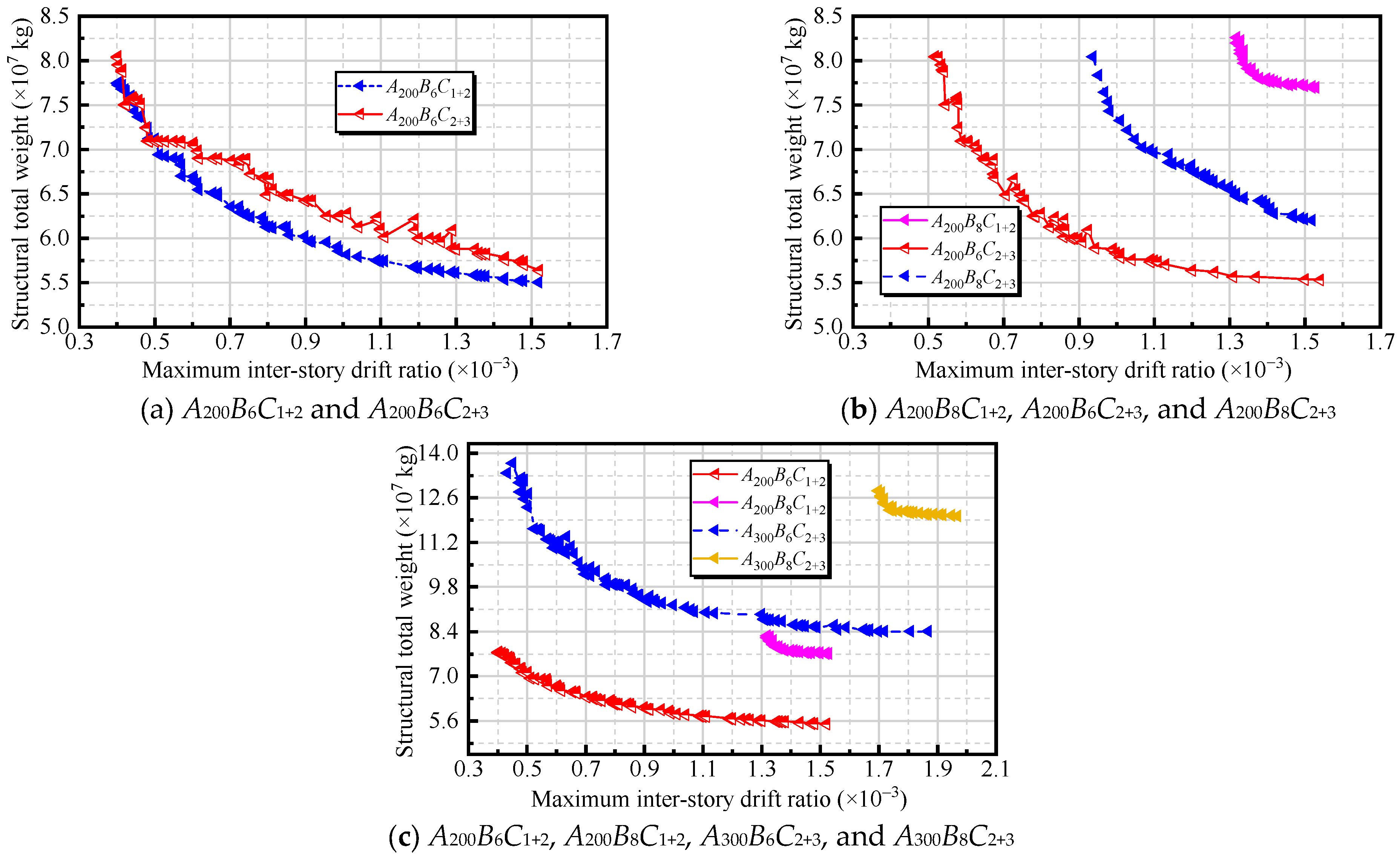
Figure 2 presents the relationship between the total structural weight and the maximum inter-story drift ratio for all cases. For the 6-degree structures, as the total weight is gradually reduced, the drift ratio increases monotonically. Once the total weight is reduced below a certain level, however, further weight reduction leads to a rapid deterioration in deformation control, and the overall optimization performance deteriorates, exhibiting a typical “boundary effect”. In the 8-degree cases, the curves lie much closer to the drift-limit lines, indicating that under higher seismic intensity, drift control becomes the dominant constraint. In this regime, the influence of weight reduction on the drift ratio is no longer linear: even a modest reduction in total weight may cause a pronounced increase in drift, and the sensitivity is significantly higher than in the 6-degree cases. The locally sawtooth-like scattered points in the figure mainly arise from the discrete combinations of structural members and the random sampling of design variables by the optimization algorithm; they are typical numerical features of discrete optimization problems and do not affect the assessment of the overall trends.
By further performing pairwise comparisons of the optimal results for cases A 200 B 6 C 1 + 2 and A 200 B 8 C 1 + 2 , as well as A 300 B 6 C 2 + 3 and A 300 B 8 C 2 + 3 , the following observations can be made. When the seismic intensity level is increased, the optimal elevations of the lower outrigger and the mid-height belt truss both shift upward, while the upper outrigger is slightly lowered, so as to enhance the constraint on the overall lateral displacement provided by the middle and lower parts of the structure.
In the 6-degree cases, the web members of the outrigger and belt trusses can preferentially adopt smaller sections (e.g., L5/L6), and the deformation performance still remains about 50% better than the code limit (e.g., an actual maximum inter-story drift ratio of 1/660 versus the limit of 1/500), leaving substantial room for economic optimization. In the 8-degree cases, however, due to the more stringent design constraints, the truss web members of the 300 m structure must be upgraded to larger sections such as L3/L4, effectively “sacrificing part of the economy” to secure sufficient stiffness. This represents an unavoidable trade-off for the combination of high seismic intensity and great building height.
A comparison of the four cases A 200 B 6 C 2 + 3 , A 300 B 6 C 2 + 3 , A 200 B 8 C 2 + 3 , and A 300 B 8 C 2 + 3 shows that the building height and the design seismic intensity jointly determine whether the optimization tends to be “economy-oriented” or “stiffness/drift-control-oriented”. For the 200 m structures, a relatively relaxed feasible region is available under both 6-degree and 8-degree seismic intensities: the cross sections of the trusses and columns can be selected within a wide range, and even after weight reduction, the maximum inter-story drift ratio still maintains a considerable margin with respect to the code limit. Therefore, at this height level, parameter tuning can be guided primarily by economic considerations.
When the height increases to 300 m, the situation changes markedly. On the one hand, the overall lateral deformation becomes more sensitive, and the feasible solutions generated by the genetic algorithm generally lie close to the drift-limit boundary. On the other hand, to maintain a reasonable lateral stiffness transfer path, a stronger configuration such as the double-outrigger plus three belt trusses (2 + 3) is required. Correspondingly, the member sizes increase systematically. Under 6-degree seismic intensity, the web members of the outrigger and belt trusses typically need to adopt L4–L5 sections, and the column cross-sectional dimensions must be controlled within approximately 1.15–2.05 m. Under 8-degree seismic intensity, to counteract the higher seismic demand, the truss web members must be upgraded to L3–L5, and the lower bound of the column dimension must be raised to around 2.55 m.
These observations indicate that for 300 m buildings—especially under 8-degree seismic conditions—the dominant optimization objective shifts from “maximizing weight reduction” to “satisfying drift control first and then pursuing economy”. In this regime, the elevations of the truss stories must be selected with greater precision; otherwise, it becomes difficult to obtain feasible solutions without significantly enlarging the column cross sections.

3.3. Comparative Analysis of Multi-Variable and Single-Variable Optimization

As summarized in Table 7, all cases considered a 300 m super-tall building designed for 6-degree seismic intensity, with a lateral system comprising two outrigger trusses and three belt trusses. Comparing Case Z with Case A 300 B 6 C 2 + 3 indicates that when only the column cross sections are optimized, the best solution under the single-variable strategy occurs at a column side length of 1.37 m. In contrast, the multi-variable collaborative optimization moderately increases the chord-member sections of the outrigger trusses and the web-member sections of all trusses, and slightly shifts upward the elevations of the mid-height belt truss and the upper outrigger truss. These coordinated adjustments enhance the lateral contribution of the truss system, thereby allowing a further reduction in column size and achieving a lower total structural weight.
Comparisons between Case H c and Case A 300 B 6 C 2 + 3 , as well as between Case H w and Case A 300 B 6 C 2 + 3 , show that optimizing either the truss member sections or the truss story levels alone can yield certain local improvements—even reaching the same truss section grades or truss elevations as those in the multi-variable optimum. However, due to the pronounced coupling among column cross sections, truss member sizes, and truss elevations, keeping the remaining variables at their baseline values limits the overall synergy; consequently, the resulting total structural weight remains higher than that achieved by the multi-variable collaborative optimization.
Moreover, comparing H c with H w indicates that the total structural weight increases by only 0.13%, whereas the maximum inter-story drift ratio decreases by approximately 36%. This suggests that, within a single-variable framework, adjusting the truss elevations is more effective than optimizing the truss member sizes. Although neither strategy leads to a substantial reduction in total weight, truss-elevation optimization can significantly improve drift control and thus enhance structural safety with essentially comparable economic efficiency.
When multi-variable collaborative optimization is adopted and the three degrees of freedom—truss member sizes, truss elevations, and column cross sections—are released simultaneously, the algorithm tends to “moderately increase the sizes of the key trusses and shift their elevations upward” so as to improve the overall lateral deformation pattern, thereby allowing the column side length to be further reduced to 1.15 m. In this case, the total structural weight is not only lower than the optimal values obtained from any single-variable strategy, but the maximum inter-story drift ratio also remains within the code limits. This indicates that for such highly coupled super-tall systems, the truss configuration and column dimensions must be considered in a unified optimization framework in order to achieve a more balanced trade-off between weight reduction and lateral/seismic performance, which in turn confirms the necessity of employing a multi-variable, multi-objective optimization approach.
To further clarify the necessity of multi-variable collaborative optimization for the strongly coupled outrigger–belt-truss–mega-column system, Table 8 presents several representative feasible solutions selected from the multi-variable optimization results of A300B6C2 + 3 (Schemes 1–6). Scheme 6 was the best feasible solution obtained from the multi-variable optimization and was used as the optimal reference. In the following discussion, the weight reduction percentage is calculated in the standard form, i.e., W i W o p t / W i × 100 % , where W i is the total structural weight of the comparison scheme and W o p t is that of Scheme 6.
For the mega-column size, single-variable optimization yielded an optimal column side length of 1.37 m. Accordingly, Scheme 1 was selected from the multi-variable solution set with the same column size. Relative to Scheme 1, Scheme 6 achieved a weight reduction of approximately 6.5%, while the maximum inter-story drift ratio of Scheme 1 was about 1.2% lower. This indicates that a column size that appears optimal under fixed baseline assumptions for the other variables does not necessarily produce a globally preferable solution when truss sections and elevations are allowed to co-vary.
For truss member sizing, single-variable optimization identified L6 as the optimal section grade. Therefore, Schemes 2 and 3 were selected from the multi-variable solution set with truss sections equal to L6. Relative to Schemes 2 and 3, Scheme 6 achieved weight reductions of approximately 16.2% and 11.5%, respectively, while the maximum inter-story drift ratio was also lower in Scheme 6.
For truss elevations, single-variable optimization suggests optimal elevations of 120 m, 162 m, and 276 m. Accordingly, Schemes 4 and 5 were selected from the multi-variable solution set with these elevations. Relative to Schemes 4 and 5, Scheme 6 achieved weight reductions of approximately 15.0% and 18.4%, respectively. This further confirms that adopting single-variable optimal truss elevations alone, without simultaneous adjustment of column size and truss member sections, does not lead to a globally optimal weight–drift compromise.
Overall, the comparisons in Table 8 provide direct evidence that mega-column size, truss member sizing, and strengthening-story elevations are strongly coupled. Single-variable optimization therefore produces conditional optima under fixed assumptions for the remaining variables, whereas globally competitive solutions require coordinated adjustments across multiple variables. From a structural-mechanism perspective, the outrigger and belt trusses act as “mega-beams” that provide effective lateral restraint to the exterior frame, redistribute internal forces among vertical members and mitigate deformation concentration, and offer lateral bracing to columns, thereby reducing their effective length. Consequently, optimizing any single parameter in isolation cannot simultaneously balance lateral stiffness allocation and gravity-system demand. These findings further support the advantage and necessity of multi-variable collaborative optimization for highly coupled super-tall building systems.


4. Engineering Case Study

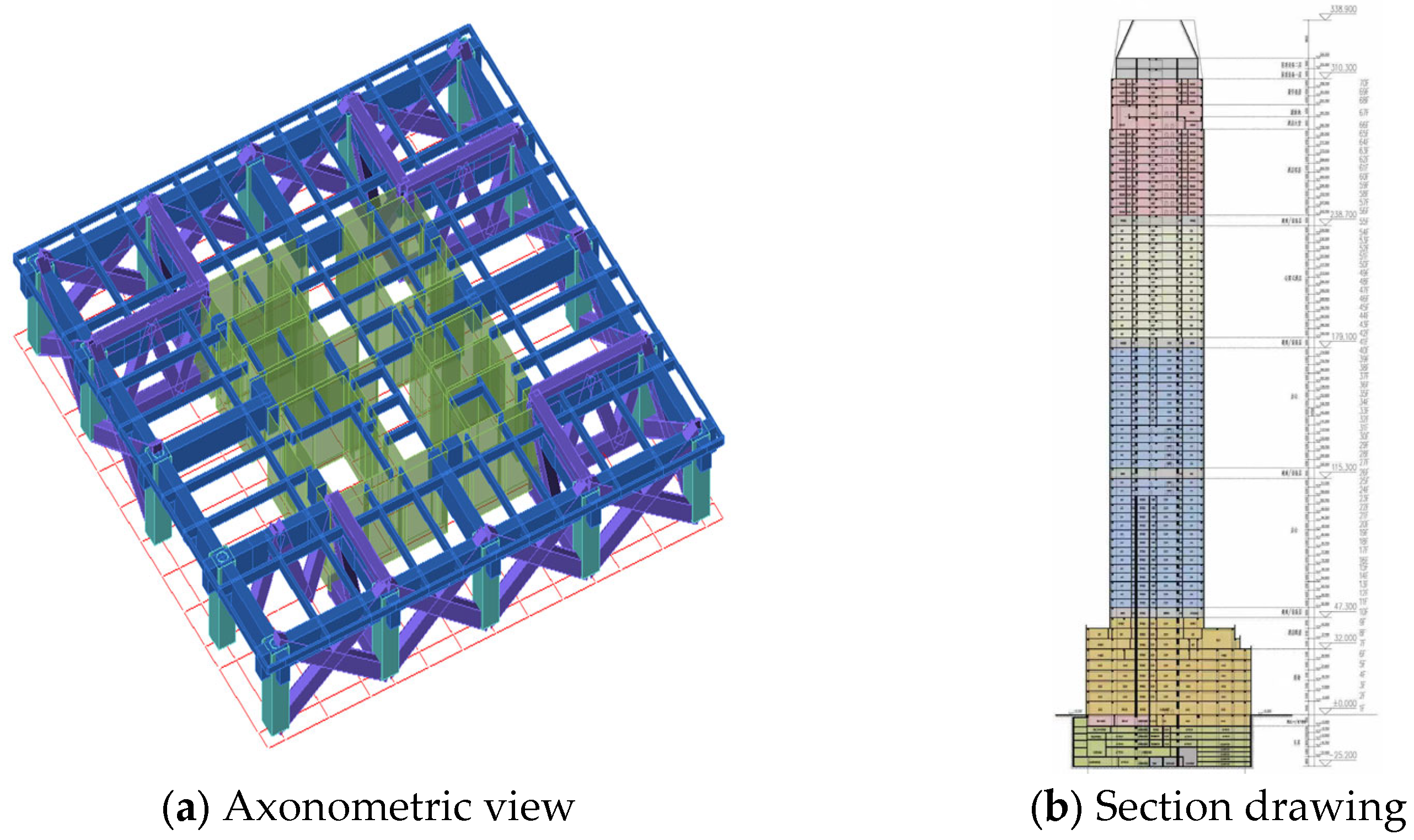
The case study in Section 4 uses the actual project-specific design inputs, which differ from the baseline settings in Table 4 (e.g., site class, characteristic period Tg, basic wind pressure and wind return period). This case study is included to demonstrate the applicability of the proposed framework under realistic engineering conditions, rather than to redefine the baseline for the parametric comparison. A practical engineering case of a financial center in Chongqing is adopted to validate the effectiveness of the proposed multi-variable optimization method by comparing the original structural scheme with the optimal layout obtained in this study. Figure 3 shows the analytical model of the financial center, which has 70 stories and a total height of 310.3 m. The structure adopts a frame–core tube system. The basic wind pressure was taken as 0.45 KN/m2, corresponding to a 100-year return period for the Chongqing region. According to the surrounding environment, the ground roughness is classified as Category C. The design seismic intensity was 6-degree, with a design basic seismic acceleration of 0.05 g. The building belongs to the first group of design earthquakes, with a structural damping ratio of 0.05, site class I1, and a site characteristic period of 0.25 s.
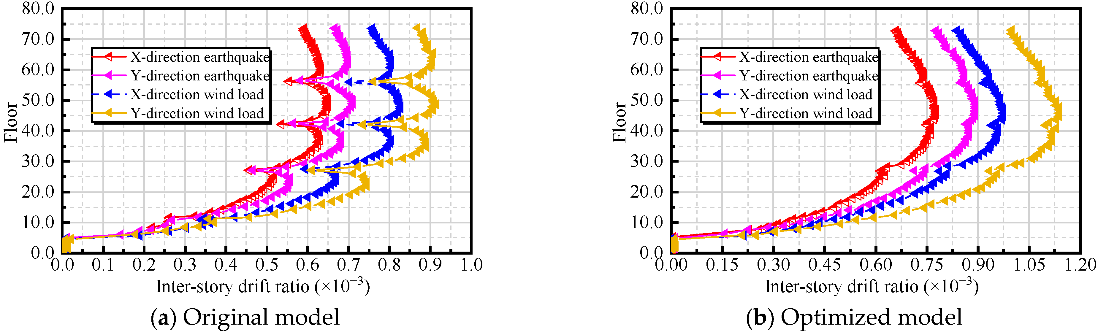
Table 9 and Figure 4 compare the original design and the optimized scheme. Relative to the original model, the optimized layout removed two outrigger truss stories and one belt truss story. Although this led to a noticeable increase in the maximum inter-story drift ratio, the original structure exhibited an excessively small drift demand and was therefore uneconomical. After optimization, the drift ratio increased but still satisfied the structural safety requirements with an adequate margin. At the same time, the amount of structural steel was significantly reduced, and the equivalent total structural weight decreased by 12.3%. These results demonstrate both the feasibility and the effectiveness of the proposed optimization method in practical super-tall building design.

5. Conclusions

1.
The advantages of multi-variable collaborative optimization are verified. When truss elevations, truss member sections, and mega-column cross sections are simultaneously treated as design variables, the proposed genetic-algorithm-based framework can identify superior designs under code constraints, including limits on inter-story drift ratio, shear-weight ratio, stiffness-weight ratio, and other prescribed indices. In contrast, the “optimal” values obtained from single-variable optimization are conditional optima derived under the assumption that all other variables remain fixed at their baseline values, and therefore cannot reliably lead to a global optimum in such a strongly coupled system. By selecting representative feasible solutions from the multi-variable solution set that coincide with these single-variable “optimal” values as benchmarks, it is shown that the multi-variable optimum reduces the total structural weight by approximately 6.5–18.4% relative to these representative solutions. Overall, single-variable optimization captures only local performance trends, whereas coordinated multi-variable adjustment enables simultaneous structural weight reduction and improved lateral performance. These results demonstrate that adopting a multi-variable collaborative optimization strategy is both necessary and practically effective for highly coupled structural systems.
2.
The optimal elevations of strengthening stories depend on building height and seismic intensity.
For a 200 m building under 6-degree seismic intensity, placing strengthening stories around 0.40 H–0.60 H and 0.85 H–0.95 H can lead to drift-compliant and relatively lightweight solutions. When the height increases to 300 m or the seismic intensity rises to 8-degree, the effective elevations shift upward, and additional truss systems (e.g., 2 outriggers + 3 belt trusses) are required to maintain lateral performance. These findings suggest that strengthening-story elevations should be treated as adjustable design variables rather than fixed empirical values.
3.
Under high seismic intensity, the feasible optimization space becomes more constrained. For 8-degree (0.20 g) design earthquakes, the optimal solutions tend to approach the inter-story drift limits, and the achievable weight reduction is smaller than in lower-intensity cases. In such conditions, satisfying deformation limits governs the optimization process, while economic improvement can only be achieved within a reduced feasible design domain.
4.
The engineering case study supports the practical applicability of the framework. When applied to the Chongqing financial center model, the optimization procedure reduces the number of strengthening stories and decreases the equivalent total structural weight by approximately 12% relative to the original design, while still satisfying code-based deformation requirements. The optimized parameter combinations can be directly implemented in conventional structural design software, facilitating rapid multi-scheme comparison during preliminary design.
Overall, for super-tall buildings with outrigger–belt truss systems, there is no single fixed optimal configuration. Instead, a performance-economy trade-off curve emerges that varies with building height, seismic intensity, and the number of strengthening stories. Integrating key structural parameters into a unified constrained optimization framework provides a systematic approach for identifying feasible and efficient design solutions. Future research may explore the integration of performance indicators such as wind-induced acceleration and occupant comfort into the existing multi-objective framework, enabling a more comprehensive assessment of the structure’s overall performance under combined wind-seismic multi-hazard actions.

Author Contributions

J.H.: Writing–original draft, Methodology, Investigation, Funding acquisition. S.D.: Investigation, Data curation, Writing—original draft, Visualization. D.Z.: Writing—review & editing, Validation, Visualization. X.C.: Investigation. L.L.: Writing—review & editing, Validation, Project administration. Y.L.: Writing—review & editing, Validation, Project administration. All authors have read and agreed to the published version of the manuscript.

Funding

This research was funded by the National Natural Science Foundation of China (grant nos. 52278481 and 52578554) and the Chongqing Housing and Urban Rural Construction Commission (grant no. 2025-21). And The APC was funded by the Overall Urban Design and Phase I Engineering Design Project of the Microelectronics Innovation Street in Western (Chongqing) Science City.

Data Availability Statement

The original contributions presented in this study are included in the article. Further inquiries can be directed to the corresponding author.

Conflicts of Interest

The authors declare no conflicts of interest.

References

  1. Park, H.S.; Lee, E.; Choi, S.W.; Oh, B.K.; Cho, T.; Kim, Y. Genetic-Algorithm-Based Minimum Weight Design of an Outrigger System for High-Rise Buildings. Eng. Struct. 2016, 117, 496–505. [Google Scholar] [CrossRef] [Scilit]
  2. Sun, F.; Yu, R.; Jia, R. Practical Optimal Design Method for Multi-Outrigger Building Structures under Inter-Story Drift Constraints. Adv. Struct. Eng. 2023, 26, 381–395. [Google Scholar] [CrossRef] [Scilit]
  3. Wang, L.; Zhao, X. Fast Optimization of Outriggers for Super-Tall Buildings Using a Sensitivity Vector Algorithm. J. Build. Eng. 2021, 43, 102531. [Google Scholar] [CrossRef] [Scilit]
  4. Kamgar, R.; Rahgozar, R. Determination of Optimum Location for Flexible Outrigger Systems in Tall Buildings with Constant Cross Section Consisting of Framed Tube, Shear Core, Belt Truss and Outrigger System Using Energy Method. Int. J. Steel Struct. 2017, 17, 1–8. [Google Scholar] [CrossRef] [Scilit]
  5. Kim, B.; Tse, K.T.; Chen, Z.; Park, H.S. Multi-Objective Optimization of a Structural Link for a Linked Tall Building System. J. Build. Eng. 2020, 31, 101382. [Google Scholar] [CrossRef] [Scilit]
  6. Huang, M.-F.; Wang, C.-H.; Lin, W.; Xiao, Z.-B. A Multi-objective Structural Optimization Method for Serviceability Design of Tall Buildings. Struct. Des. Tall Spec. Build. 2023, 32, e2052. [Google Scholar] [CrossRef] [Scilit]
  7. Alanani, M.; Brown, T.; Elshaer, A. Multiobjective Structural Layout Optimization of Tall Buildings Subjected to Dynamic Wind Loads. J. Struct. Eng. 2024, 150, 04024069. [Google Scholar] [CrossRef] [Scilit]
  8. Lotfy, S.; El Madawy, M.E. Optimization of Diagrid Tall Buildings for Seismic Response Using the Parameter Space Multi-Objective Method. J. Build. Eng. 2023, 80, 108080. [Google Scholar] [CrossRef] [Scilit]
  9. Xing, L.; Gardoni, P.; Yu, J.; Zhou, Y.; Zhang, P. Multi-Objective Optimization of High-Rise Buildings with Outrigger Systems Subject to Seismic Loads. J. Build. Eng. 2025, 111, 113197. [Google Scholar] [CrossRef] [Scilit]
  10. Liu, C.; Wang, B.; Ma, Y.; Wu, Z. Multi-Objective Optimization Design of High-Rise Diagrid Structure Based on Non-Dominated Sorting Genetic Algorithm II. J. Build. Eng. 2025, 108, 112801. [Google Scholar] [CrossRef] [Scilit]
  11. Angelucci, G.; Cecca, E.; Mollaioli, F. Parametric Analysis of Outrigger Systems for High-Rise Buildings with Different Geometric Shapes. Appl. Sci. 2025, 15, 5643. [Google Scholar] [CrossRef] [Scilit]
  12. Xing, L.; Gardoni, P.; Zhou, Y.; Zhang, P. Optimal Models of Outrigger Locations and Damping Parameters for Combined Energy Dissipation Outrigger Systems Subject to Seismic and Wind Loads. J. Build. Eng. 2023, 76, 107209. [Google Scholar] [CrossRef] [Scilit]
  13. Zheng, K.Q. Performance Analysis and Optimal Design of Strong Outer Frame or Tube Structural System of Super High-Rise Building. Master’s Thesis, Guangzhou University, Guangzhou, China, 2025. [Google Scholar]
  14. Chen, J.J. An Improved Genetic Algorithm and Its Application in Optimal Configuration of Dampers. Master’s Thesis, Guangzhou University, Guangzhou, China, 2018. [Google Scholar]
  15. Katkhoda, A.; Knaa, R. Optimization in the Selection of Structural Systems for the Design of Reinforced Concrete High-Rise Buildings in Resisting Seismic Forces. Energy Procedia 2012, 19, 269–275. [Google Scholar] [CrossRef] [Scilit]
  16. Liu, C.D.; Qin, K.; Lu, Q.G.; Li, Y.; Liu, Y.H.; Shi, Y.S.; Wang, J.L.; Liu, H. Optimization Analysis on a Super High-Rise Tower in Low Intensity Area. Build. Struct. 2024, 54, 57–62, 80. [Google Scholar] [CrossRef]
  17. Cabrera, P.A.; Medina, G.M.; Delgadillo, R.M. Automation and Genetic Algorithm Optimization for Seismic Modeling and Analysis of Tall RC Buildings. Buildings 2025, 15, 3618. [Google Scholar] [CrossRef] [Scilit]
  18. Zhang, W.; Zhao, Y.; Wu, Z.; Zhao, J.; Wang, S. The Application of Genetic Algorithm in Seismic Performance Optimization of a Y-Eccentrically Braced Composite Frame. Buildings 2025, 15, 770. [Google Scholar] [CrossRef] [Scilit]
  19. Kennedy, J.; Eberhart, R. Particle Swarm Optimization. In Proceedings of the ICNN’95—International Conference on Neural Networks, Perth, WA, Australia, 27 November–1 December 1995; IEEE: Perth, WA, Australia, 1995; Volume 4, pp. 1942–1948. [Google Scholar]
  20. Kirkpatrick, S.; Gelatt, C.D.; Vecchi, M.P. Optimization by Simulated Annealing. Science 1983, 220, 671–680. [Google Scholar] [CrossRef] [Scilit] [PubMed]
  21. Dorigo, M.; Maniezzo, V.; Colorni, A. Ant System: Optimization by a Colony of Cooperating Agents. IEEE Trans. Syst. Man Cybern. Part B Cybern. 1996, 26, 29–41. [Google Scholar] [CrossRef] [Scilit] [PubMed]
  22. Holland, J.H. Adaptation in Natural and Artificial Systems: An Introductory Analysis with Applications to Biology, Control, and Artificial Intelligence; MIT Press: Cambridge, MA, USA, 1992. [Google Scholar]
  23. MOHURD. GB 50009-2012; Code for Design of Building Structures Loads. China Architecture & Building Press: Beijing, China, 2012.
Figure 1. Performance indices of single-variable optimization.
Buildings 16 01324 g001
Figure 2. Relationship between total structural weight and maximum inter-story drift angle for each case.
Buildings 16 01324 g002
Figure 3. Model of a financial center in Chongqing (PKPM).
Buildings 16 01324 g003
Figure 4. Maximum inter-story drift ratio.
Buildings 16 01324 g004
Table 1. Single-variable case studies.
Case StudyColumn SizeTruss Dimensions Truss Elevation
ZVariableFixed valueFixed value
H c Fixed valueVariableFixed value
H w Fixed valueFixed valueVariable
Table 2. Truss section library.
SectionSize (mm)
L11600 × 1400 × 1400 × 30 × 30 × 30
L21400 × 1200 × 1200 × 30 × 30 × 30
L31200 × 1000 × 1000 × 20 × 20 × 20
L41000 × 800 × 800 × 20 × 20 × 20
L5800 × 600 × 600 × 20 × 20 × 20
L6700 × 500 × 500 × 20 × 20 × 20
Table 3. Multi-variable case studies.
CaseBuilding Height (m)Seismic IntensityNumber of Outrigger TrussesNumber of Belt TrussesNumber of Feasible Solutions
A 200 B 6 C 1 + 2 200Intensity VI (0.05 g)1282
A 200 B 6 C 2 + 3 200Intensity VI (0.05 g)2391
A 200 B 8 C 1 + 2 200Intensity VIII (0.2 g)1230
A 200 B 8 C 2 + 3 200Intensity VIII (0.2 g)2352
A 300 B 6 C 1 + 2 300Intensity VI (0.05 g)1256
A 300 B 6 C 2 + 3 300Intensity VI (0.05 g)23120
A 300 B 8 C 2 + 3 300Intensity VIII (0.2 g)2328
Table 4. Summary of load conditions.
Load TypeParameterValue/Description
Dead loadFloor dead load5.0 kN/m2
Live loadOffice floor live load2.0 kN/m2
Wind loadBasic wind pressure (50-year return period)0.4 kN/m2
Ground roughness categoryCategory B
Seismic actionSeismic intensity (6-degree/8-degree)0.05 g/0.2 g
Site classSite class II
Site characteristic period0.35 s
Table 5. Optimal results for each case (single variable).
ParameterHwHcZ
Column cross section (m)1.401.401.37
Outrigger chord member section (mm)800 × 600 × 600 × 20 × 20 × 20700 × 500 × 500 × 20 × 20 × 20800 × 600 × 600 × 20 × 20 × 20
Truss web member section (mm)700 × 500 × 500 × 20 × 20 × 20700 × 500 × 500 × 20 × 20 × 20700 × 500 × 500 × 20 × 20 × 20
Belt truss chord member section (mm)800 × 600 × 600 × 20 × 20 × 20700 × 500 × 500 × 20 × 20 × 20800 × 600 × 600 × 20 × 20 × 20
Truss elevation (m)120/162/276120/150/270120/150/270
Maximum inter-story drift ratio1/8551/5431/529
Total structural weight (×107 kg)8.22958.22438.1729
Table 6. Optimal results for each case (multi-variable).
CaseOutrigger Chord MemberWeb MemberBelt Truss Chord MemberLower Outrigger Elevation (m)Belt Truss Elevation (m)Upper Outrigger Elevation (m)Column Side Length (m)Equivalent Total Weight (t) Inter-Story Drift
A 200 B 6 C 1 + 2 L5L6L3112158-1.2054,9571/660
A 200 B 6 C 2 + 3 L5L5L5721041801.0855,2781/651
A 200 B 8 C 1 + 2 L5L3L5120172-2.4976,9351/652
A 200 B 8 C 2 + 3 L5L3L5761081681.4861,9871/659
A 300 B 6 C 1 + 2 L4L5L260249-2.05100,6101/601
A 300 B 6 C 2 + 3 L3L4L51201632791.1583,9371/580
A 300 B 8 C 2 + 3 L2L5L61381742642.55120,2761/508
Table 7. Comparison of optimal solutions for single-variable vs. multi-variable optimization ( A 300 B 6 C 2 + 3 ).
CaseOutrigger Chord MemberWeb MemberBelt Truss Chord MemberLower Outrigger Elevation (m)Belt Truss Elevation (m)Upper Outrigger Elevation (m)Column Side Length (m)Equivalent Total Weight (t) Inter-Story Drift
ZL5L6L51201502701.3785,6521/529
HcL6L6L61201502701.4085,8451/543
HwL5L6L51201622761.4085,9601/855
A 300 B 6 C 2 + 3 L3L4L51201632791.1583,9371/580
Table 8. Comparison of representative solutions selected from the multi-variable optimization set with the optimal solution (A300B6C2 + 3).
SchemeR3R2R1Lower Truss Elevation (m)Belt Truss Elevation (m)Upper Truss Elevation (m)Column Side Length (m)Total Structural Weight (t)Maximum Inter-Story Drift Ratio
Scheme 1L2L3L31431652791.3789,7340.001702
Scheme 2L6L6L61251812511.87100,1100.001775
Scheme 3L6L6L6981662581.6794,7970.001983
Scheme 4L3L4L31201622761.8298,7070.000796
Scheme 5L3L5L41201622761.98102,8490.000735
Scheme 6L3L4L51201632791.1583,9370.001724
Table 9. Comparison between the original model and the optimized model for a financial center in Chongqing.
ParametersOriginal ModelOptimized Model
Outrigger chord section (mm)Box Section 1000 × 1000 × 50 × 50 × 50 × 50I-Section 1200 × 1000 × 1000 × 20 × 20 × 20
Web member cross-section (mm)Box Section 1000 × 1000 × 50 × 50 × 50 × 50I-Section 1000 × 800 × 800 × 20 × 20 × 20
Ring truss chord cross-section (mm)Box Section 1000 × 1000 × 50 × 50 × 50 × 50I-Section 800 × 600 × 600 × 20 × 20 × 20
Truss elevation (m)47/115/179/238124/166/285
Max inter-story drift ratio (X-dir.)1/1214 < [1/500]1/596 < [1/500]
Max inter-story drift ratio (Y-dir.)1/1101 < [1/500]1/583 < [1/500]
Equivalent total weight (×107 kg)28.991625.4271
Disclaimer/Publisher’s Note: The statements, opinions and data contained in all publications are solely those of the individual author(s) and contributor(s) and not of MDPI and/or the editor(s). MDPI and/or the editor(s) disclaim responsibility for any injury to people or property resulting from any ideas, methods, instructions or products referred to in the content.