Article

Aggregated vs. Isolated Seismic Response of a Historic Masonry Compound Before and After Integrated Retrofit Interventions


by
Giovanna Longobardi
* and
Antonio Formisano
Department of Structures for Engineering and Architecture, School of Polytechnic and Basic Sciences, University of Naples “Federico II”, Piazzale Tecchio 80, 80125 Naples, Italy
*
Author to whom correspondence should be addressed.
Buildings 2026, 16(6), 1208; https://doi.org/10.3390/buildings16061208
Submission received: 8 January 2026 / Revised: 2 March 2026 / Accepted: 16 March 2026 / Published: 18 March 2026

Abstract

The evaluation of the seismic behavior of masonry aggregates, which characterize Italian historic centres, is a challenging and widely debated topic in the field of structural engineering. These constructions, composed of several adjacent structural units, tend to exhibit both global and local damage when subjected to horizontal seismic actions—loads that were not considered at the time of their original construction. Developed over centuries of unplanned urban growth, they are based on empirical construction rules and locally sourced materials. Due to their poor thermal properties, these buildings are also affected by significant heat losses, resulting in reduced indoor comfort. In this context, the present study aims to evaluate the seismic performance of a masonry aggregate and two of its constituent structural units located in Visso, in the province of Macerata, an area severely affected by the 2016 Central Italy seismic sequence, both before and after the application of an innovative integrated retrofitting solution. The proposed strengthening system combines aluminium alloy exoskeleton with insulating sandwich panels, simultaneously addressing seismic vulnerability and energy inefficiency. The assessment is carried out through numerical analyses, including nonlinear static and dynamic approaches, to achieve a comprehensive understanding of the structural response. Moreover, a comparative analysis between the masonry aggregate and the two individual structural units, modelled as isolated buildings, is performed to investigate the influence of structural interaction among adjacent units. The results demonstrate the effectiveness of the proposed retrofitting strategy, highlighting a significant improvement in global stability. Furthermore, the comparison confirms the critical role of inter-unit interaction and underscores the necessity of modelling historic masonry aggregates rather than isolated buildings to obtain a more realistic seismic performance evaluation.

1. Introduction

The fragility of the existing masonry building stock has been repeatedly highlighted by numerous earthquakes, such as the 2009 L’Aquila event and the 2016 Central Italy seismic sequence, which have struck Italy along the Apennine ridge in recent decades, as well as by recent seismic events in other active regions worldwide, including Morocco, Turkey, and Syria. This high level of vulnerability arises from a combination of intrinsic and extrinsic factors, among which the lack of adequate preventive maintenance over past decades plays a significant role. However, the primary source of structural inefficiency is mainly intrinsic and lies in the absence of seismic design criteria, as these buildings were erected prior to the introduction of modern seismic codes and were therefore conceived to withstand gravitational loads only [1,2,3,4,5,6].
Furthermore, most masonry buildings were constructed using materials with poor mechanical properties, often sourced locally near the construction site. In line with traditional construction practices—originating from early stone-building techniques based on natural, unshaped blocks—masonry units were frequently arranged in a random manner. This resulted in irregular textures and misaligned vertical joints, which further reduce the strength and load-bearing capacity of masonry walls [7,8].
To prevent future disasters and large numbers of casualties, there is an urgent need to safeguard this architectural heritage by enhancing its capacity to resist seismic actions. A wide range of retrofitting techniques is currently available, spanning from traditional approaches to innovative methods based on the use of natural fibres or integrated systems. Among the latter, external coating systems have proven particularly effective due to their dual function of improving seismic performance while simultaneously reducing energy inefficiency [9,10,11].
Indeed, existing buildings often exhibit significant thermal losses resulting from materials with poor thermal properties (e.g., high thermal transmittance), the presence of thermal bridges, and construction defects. The adoption of integrated retrofit solutions also facilitates compliance with recent European directives aimed at reducing environmental impact, considering that the construction sector is responsible for more than 50% of pollutant-related emissions [12,13,14,15].
Beyond heavier interventions, such as cast-in-place reinforced concrete shear walls, the most commonly adopted technologies rely on metal base frames infilled with insulating panels. These frames may be realized using either cold-formed steel or aluminium alloy profiles [16,17,18,19,20].
Within this framework, the present study investigates the seismic behavior of a masonry complex located in the city of Visso, an area characterized by high seismic hazard, by analysing its performance before and after the installation of a novel integrated seismic–energy coating system, known as MIL15.s. Masonry aggregates represent a substantial portion of the Italian building stock, and their seismic assessment is particularly challenging due to the interaction among adjacent structural units (SUs), which are typically not effectively connected to one another [21,22,23]. To evaluate the influence of the so-called “aggregate effect,” the seismic response of the entire compound was compared with that of two individual structural units modelled as isolated buildings. In both cases, retrofitted configurations were also investigated to assess the benefits provided by the integrated MIL15.s coating system.
These investigations were carried out through the development of Frame by Macro-Element (FME) numerical models and the execution of both nonlinear static and nonlinear dynamic analyses, thereby enabling a comprehensive assessment of structural performance.

2. Description of the Case Study in Visso

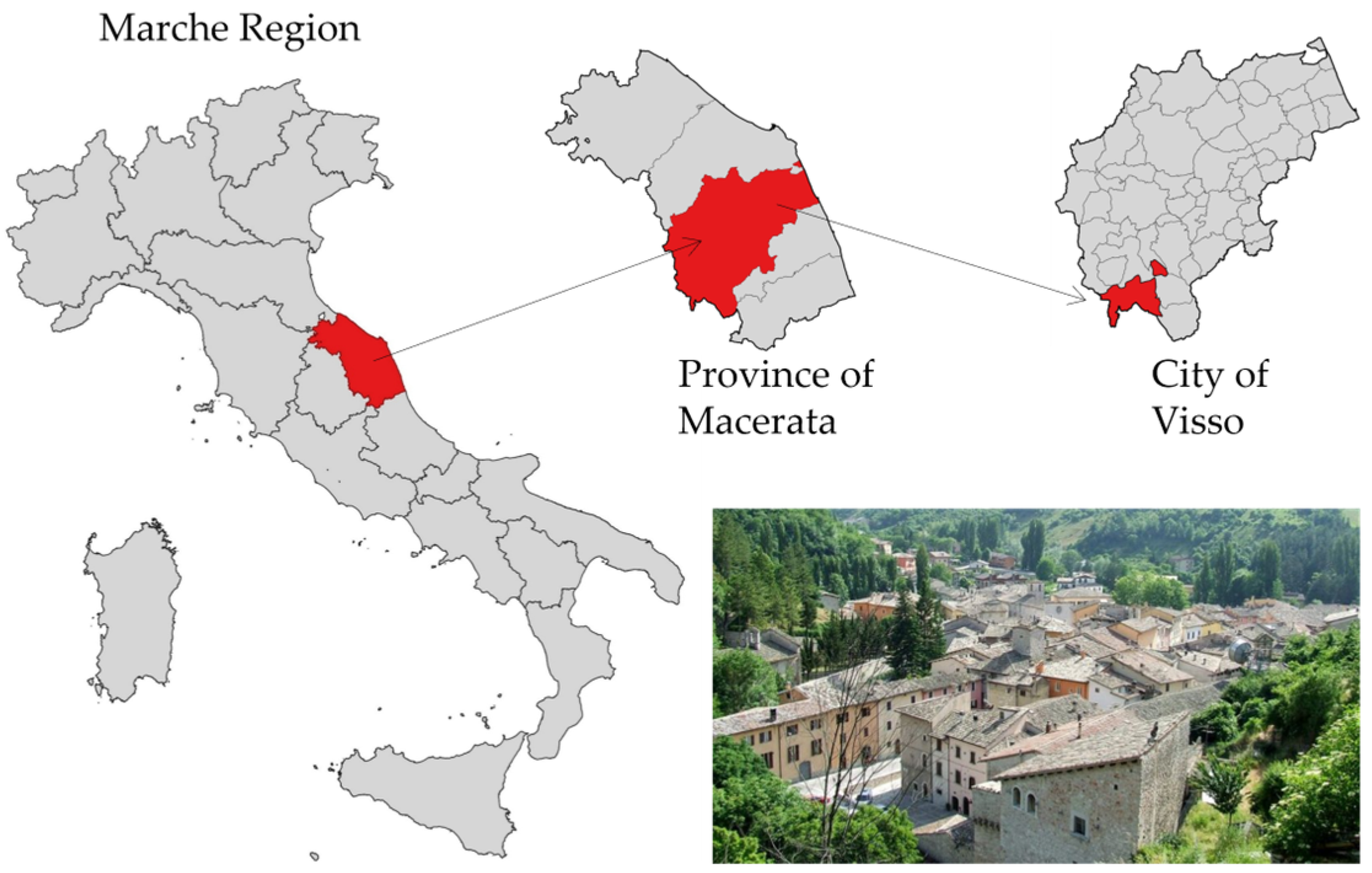
The masonry compound under investigation is located in the small town of Visso, in the province of Macerata, within the Marche region of Italy. Visso has a population of fewer than 1000 inhabitants and covers an area of approximately 100 km2. The town is situated in the Nera River valley and lies within the broader territory of the Monti Sibillini National Park. Its geographical location is shown in Figure 1.
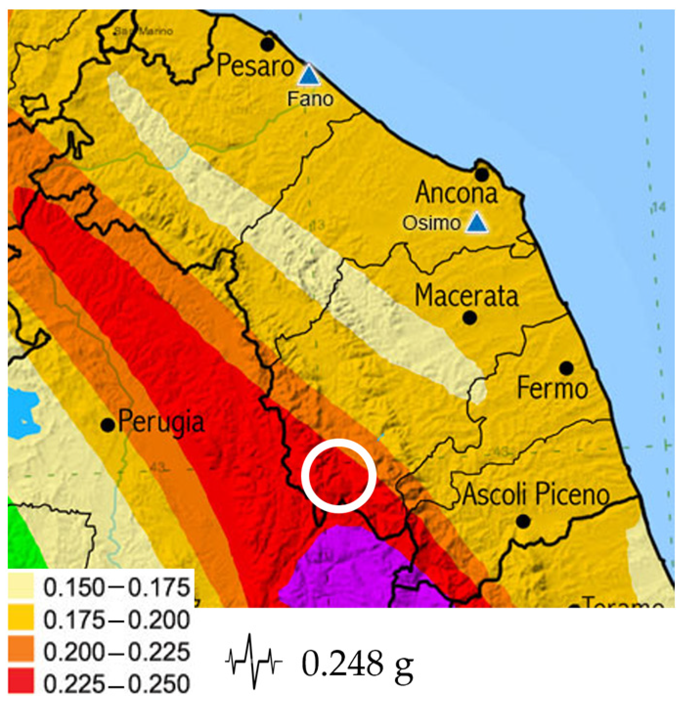
The city, classified as a high seismic hazard zone [24] together with many nearby towns (Figure 2), was severely affected by the earthquake sequence that struck the area between August and October 2016. The first major shock occurred near Amatrice on 24 August with a magnitude of 6.0. After several minor tremors, an aftershock took place in October of the same year, reaching a magnitude of 6.5. The effects of these devasting events caused over 300 casualties, the displacement of thousands of residents, and extensive damage to the building stock [25].
Many structures experienced both global and partial overturning phenomena, particularly involving perimeter walls. Significant damage was also recorded on historic constructions of high architectural and artistic value. As observed after similar catastrophic events, these earthquakes clearly highlighted the fragility of the existing building stock and the urgent need for adequate reinforcement strategies.
In recent years, a comprehensive program of reconstruction and consolidation has been undertaken, with the aim of revitalizing the urban fabric while improving the seismic resilience of the existing buildings. Particular attention has been paid to maintain the historical identity of these towns while ensuring the safety of the population.
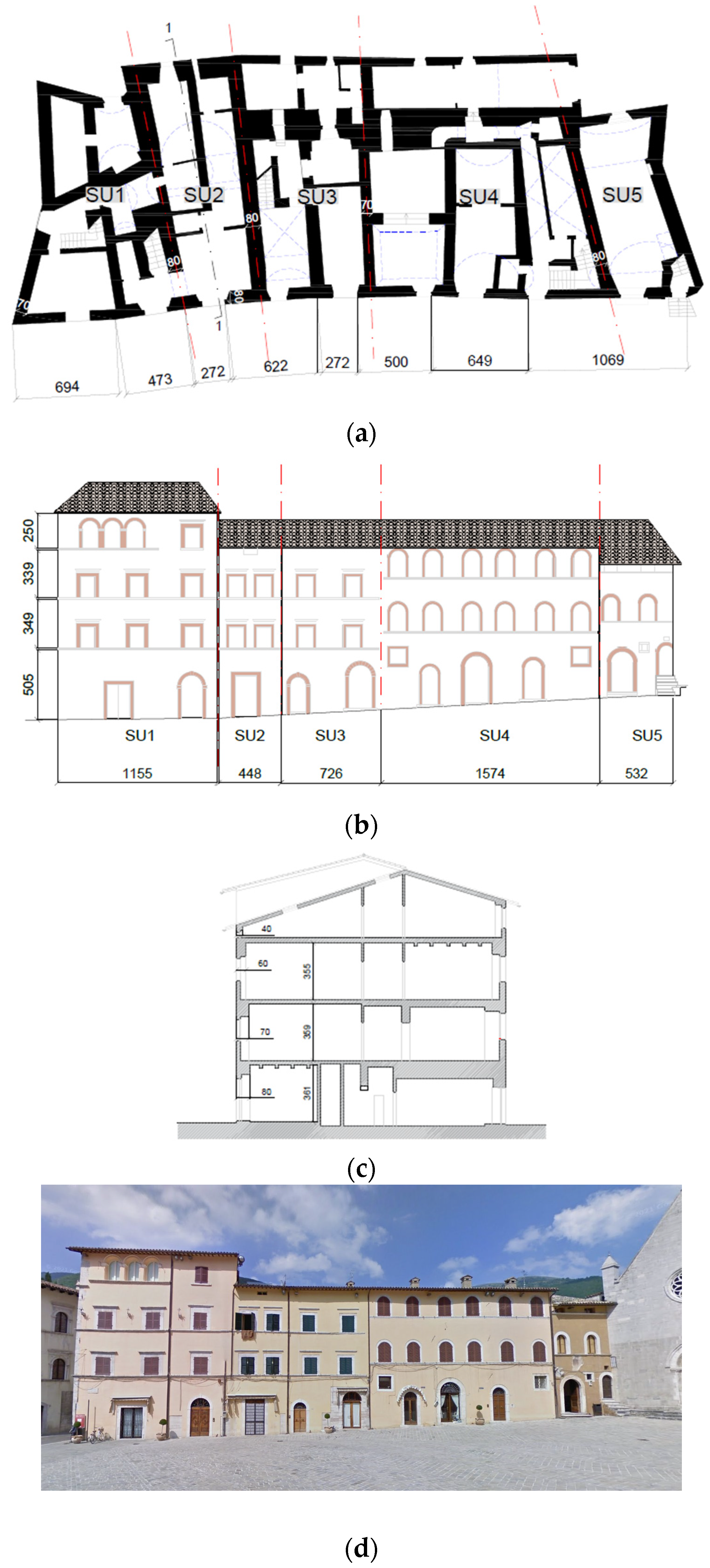
The case study is a masonry compound located in a central position within the historic centre of Visso, overlooking Martiri Vissani Square and situated near the Collegiate Church of Saint Mary, the town’s main religious place. The constitutive units of this masonry aggregate exhibited various types of failure, including incipient overturning mechanisms, widespread cracks around openings, and deterioration of the masonry walls. The complex consists of five SUs dating back to the early 1900s, built in continuity using irregular calcareous masonry. Each cell shares its boundary walls with the adjacent ones. The layout and the main façade along the square are depicted in Figure 3.
The wall thickness varies from 80 cm on the ground floor to 70–60 cm on the upper levels, reaching 40 cm on the top level. Most of the spaces at the ground floor are covered by masonry vaults, whereas the other horizontal floors are made of timber beams supporting a single layer of plank. The roof of all of the units has a traditional double-pitched configuration sustained by timber beams. The masonry walls of the aggregate, made of irregular calcareous stone, are arranged with a non-homogeneous texture. The construction technique is representative of early 20th century buildings in the Apennine area, where locally sourced materials and empirical rules were commonly adopted. The masonry texture shows the absence of regular through-stones and limited transversal connections, which negatively affects both strength and stiffness.
Since no experimental tests were conducted on the materials, the mechanical properties of the masonry were defined according to Table C8.5.I of the Ministerial Circular of the Italian Technical Code for Constructions, assuming the lowest Knowledge Level (KL1) [26,27]. In compliance with the code provisions, a confidence factor equal to 1.35 was adopted in order to account for the high level of uncertainty associated with the mechanical characterization of existing materials. Average values were assumed for the elastic moduli, while minimum ones were selected for the strength parameters, as reported in Table 1.
In the absence of detailed information regarding the type of timber used for the beams, the most common species in the area were selected, whose mechanical characteristics were derived from the UNI EN 338:2004 standard “Structural Timber–Strength Classes” [28], as listed in Table 2. Specifically, beech wood, which belongs to the hardwood category and corresponds to strength class D30, was chosen. The beams were assumed to have a cross-section of 20 × 30 cm spaced at approximately 1 m. The floor system was completed with a plank layer of about 3 cm and made of the same wood species. The floor was then completed with a light screed and the final floor finishes. The modification factor kmod, which accounts for the influence of load duration and moisture content on the strength parameters, was set as equal to 0.6. This value results from assuming Service Class 1, defined by moisture conditions and exposure, and a permanent load duration class. The same wood species was also assumed for the structural elements supporting the roof.
For the vaulted structures located at the ground floor, the infill was assumed to consist of calcareous stones, consistent with the material used for the vertical walls, completed by a screed layer and the final floor finishing.

3. A Novel Retrofit Solution: The MIL15.s External Coat

3.1. Scheme of Functioning

The selected retrofitting solution is the MIL15.s external coating system, patented by TM Group S.r.l. (Montegranaro, Province of Fermo, Marche Region, Italy). The system combines a structural exoskeleton composed of aluminium alloy components with insulating sandwich panels, consisting of double trapezoidal steel sheeting with an internal insulation core [29].
The aluminium alloy used for the exoskeleton belongs to the 6000 series, which is commonly adopted in structural applications due to its favourable mechanical properties. Specifically, the system employs alloy 6060, which, according to the CNR-DT 208/2011 Guidelines and Eurocode 9 [30,31], is characterized by a 0.2% proof strength f 0.2 of 150 MPa and an ultimate tensile strength f u of 190 MPa. The material exhibits an ultimate strain of approximately 8%. These mechanical properties are summarized in Table 3.
The aluminium alloy vertical components of the system are produced through an extrusion process, which allows for the creation of a wide range of geometries and shapes, which is followed by artificial ageing (T6).
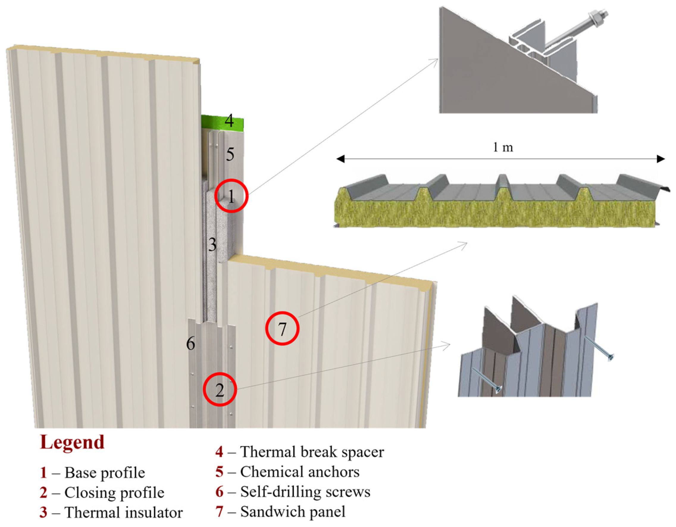
A view of the retrofit system, including its components and connections, is shown in Figure 4. In particular, the first element, referred to as the base profile (Element No. 1), is anchored to the perimeter masonry walls using 12 mm chemical anchors spaced at 50 cm intervals (El. No. 5). Between two consecutive base profiles, placed approximately 1 m apart, a sandwich panel (El. No. 7) is inserted and fixed with self-drilling screws (El. No. 6). Once the additional components designed to limit thermal dispersion are positioned (El. Nos. 3 and 4), the system is finalized with the aluminium closing profile (El. No. 2). Its flanges interlock with the base element, while its wings attach to the external trapezoidal sheeting of the sandwich panel.

3.2. Main Advantages

The selected retrofit system for the masonry case study in Visso is a representative example of an external coat, a novel technique designed for the combined seismic-energy upgrading of existing masonry and reinforced concrete buildings. Its primary advantage is the application from the building outside, which avoids disruption of internal activities and prevents the displacement of occupants. This feature makes the system particularly suitable not only for residential structures but also for buildings with diverse functions, such as schools and offices.
The use of aluminium alloy components further enhances the solution’s applicability. With a density approximately one third that of steel, aluminium adds minimal mass to the existing structure [30,31]. Additionally, aluminium is completely sustainable: at the end of its service life, it can be fully remelted and recycled without losing its physical or mechanical properties, significantly reducing pollutant emissions and supporting the objectives of the European Green Deal [12]. For reference, producing one ton of primary aluminium requires 14–16 MWh of energy, whereas recycling consumes only 0.7–0.8 MWh, about 5% of the original energy requirement, substantially lowering CO2 emissions [32].
Italy ranks third worldwide in aluminium recycling, following the USA and Japan, and produces one of the highest volumes of recycled aluminium. According to the latest CiAL report (National Aluminium Packaging Consortium), in 2021 Italy recycled 52,900 tons of aluminium packaging, representing 67.5% of the 78,400 tons placed on the market, positioning it among the global leaders in aluminium recycling [33].
A further key advantage of this retrofit technique is its dual purpose: it enhances structural performance while simultaneously reducing thermal dispersion, which predominantly originates from vertical partitions. This combined potential highlights the competitiveness of the technology compared to traditional interventions that primarily address structural deficiencies alone.
For these reasons, its cost of approximately EUR 150 per square meter, including preliminary works and installation, is economically sustainable and reasonable. Moreover, due to the high natural corrosion resistance of aluminium, the system requires minimal maintenance, further reducing long-term management costs.
Despite the numerous advantages discussed above, the applicability of the proposed retrofitting solution should be carefully evaluated in historic contexts. In particular, the installation of the external coating system may not be suitable for facades of buildings covered by cultural, artistic, or architectural bonds, as these surfaces are often required to retain their original appearance. For this reason, the proposed solution is mainly intended for non-monumental historic buildings. The visual impact of the system can be mitigated by adopting suitable finishing layers; however, its use in protected historic city centres must always be assessed on a case-by-case basis and approved by competent authorities.

4. Modelling of the Complex Using an FME Approach

4.1. Aggregated vs. Isolated Configurations Before and After the Installation of the MIL15.s

Following the acquisition of the geometric and structural properties of the aggregate, the modelling phase begins with the creation of a Frame by Macroelement (FME) model developed using the 3Muri computer software 15.0.0.1 developed by the STA.DATA company [34]. This approach, based on the observation of damage affecting real buildings after seismic events, proposes the division of masonry walls into three macro-elements: piers adjacent to openings, spandrels located above and/or below the openings, and rigid nodes as the remaining parts between piers and spandrels, assumed to behave as infinitely rigid.
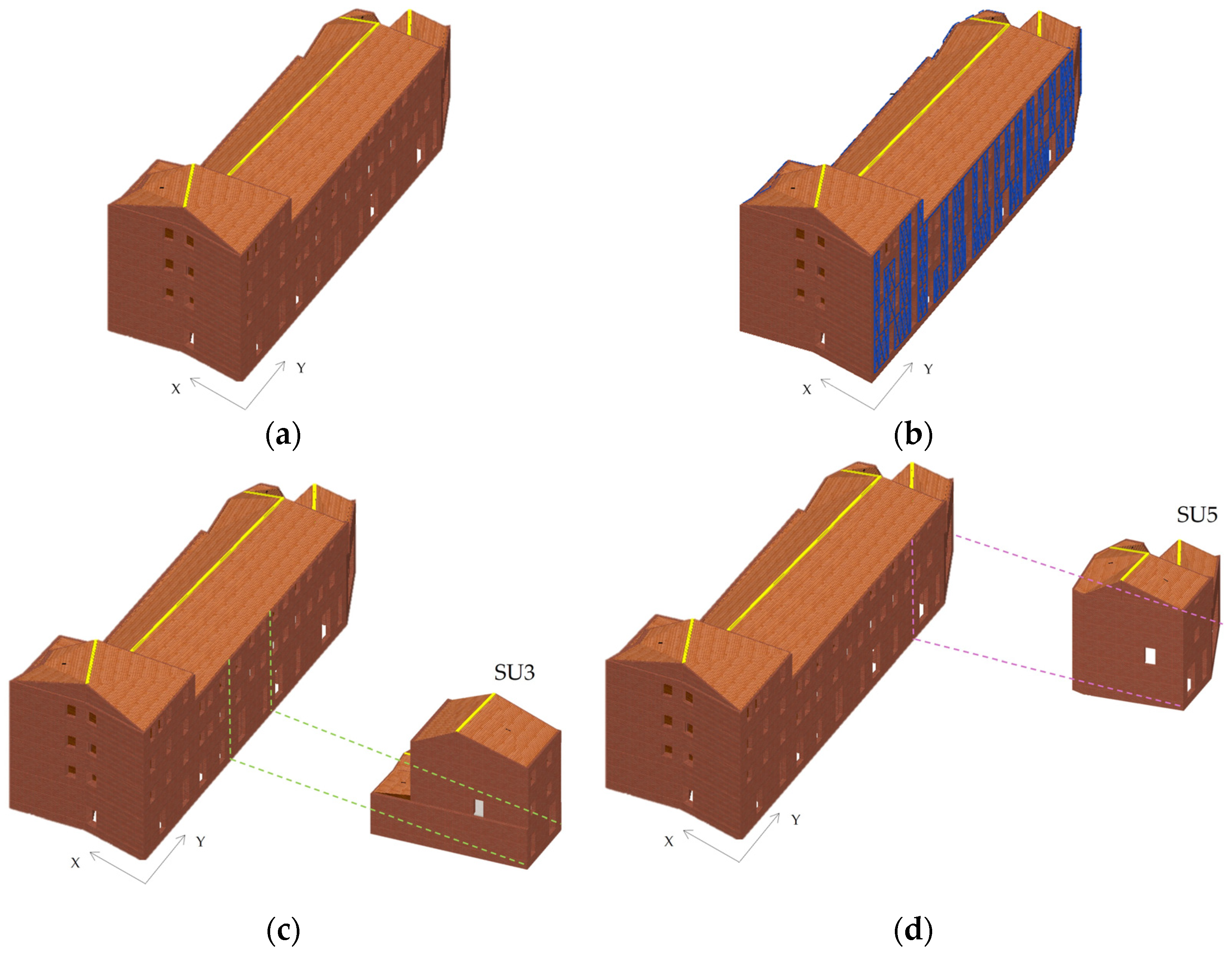
Specifically, three models were created. One corresponds to the entire masonry compound, while the other two represent individual structural units modelled as isolated buildings. When analysing an isolated structural unit (SU), half of the thickness of the boundary wall was considered, as adjacent units share common walls. The two units analysed in isolation are SU3 and SU5. SU3 is an internal unit spanning three levels above the floor, while SU5 is a corner unit comprising only two levels.
The behavior of the structures was also investigated taking into account the presence of the integrated seismic-energy retrofitting solution described in the previous section. In order to introduce the presence of the external coat, vertical elements representing the aluminium alloy base profiles were inserted within the software environment. The connection between these external profiles and the perimeter masonry walls was simulated through rigid links. The sandwich panel, for computational efficiency and following several studies [35], was schematized as an equivalent diagonal truss with a full circular cross-section. This modelling strategy is capable of accurately reproducing the in-plane shear stiffness of the panels. Its diameter was calculated using Equation (1):
Adiag = Keq ∙ Leq/(E ∙ cos2α),
where
  • E stands as the elastic modulus of the material.
  • Leq is the equivalent length of the element, calculated as the ratio b/cosα, with b representing the frame width and α = arctg h/b, considering h as the frame height.
  • Keq is the equivalent stiffness. It originates from the shear flexibility of the diaphragm.
The parameter C’, which accounts for the shear flexibility of different components, such as sheeting and fasteners, was determined by means of Equation (2):
Keq = 1/C’
The three-dimensional model of the entire aggregate in both conditions (isolated and aggregated), along with the location of the two selected SUs extracted from the complex, are shown in Figure 5.
The integrated seismic–energy retrofit system was applied to the main facades of all SUs of the masonry complex, facing Martiri Vissani Square, as well as to the rear facades. Conversely, the lateral facades of SU1 and SU5 were not retrofitted, as they are not completely free and are partially constrained by adjacent constructions. This intervention layout was defined in order to maximize the effectiveness of the strengthening solution while respecting the geometric and urban constraints of the compound.
Regarding the presence of openings, the aluminium alloy vertical profiles are generally arranged with a regular spacing of approximately 1.0 m. However, the presence of windows, doors, or other openings may require the use of special elements with reduced modular spacing. This allows the system to be properly adapted to the existing façade geometry without interfering with the architectural layout of the openings, while maintaining the structural continuity and effectiveness of the external coating system.

4.2. Execution of Nonlinear Static and Dynamic Analyses

Once all models were defined, analyses were carried out to investigate the performance of the selected case study.
Firstly, nonlinear static analyses (NLSAs) were conducted assuming two distributions of horizontal loads, as prescribed by the Italian Technical Code. During the NLSAs, the displacement of a top control node located at the barycentre of the structure was monitored to assess the overall performance of the complex by gradually increasing lateral forces. The results were evaluated in terms of the following:
  • The αSLV coefficient, related to the Life Safety Limit State (LSLS or SLV), defined as the ratio of capacity to demand peak ground accelerations (PGAC/PGAD);
  • Capacity curves, representing the relationship between base shear and top displacement.
The same procedure was applied to the two isolated structural units (SUs) in both as-built and retrofitted configurations.
Additionally, to comprehensively capture the structural behavior of the complex, nonlinear dynamic analyses (NLDAs) were performed. These simulations allow for the evaluation of structural response under realistic earthquake conditions using accelerograms, which are records of ground acceleration over time. The accelerograms were obtained from the Rexel web platform, a freely accessible resource providing ground motion records based on input parameters such as the reference site’s geographical data (latitude and longitude) and stratigraphical conditions [36,37]. The platform generates spectrum-compatible ground motion, meaning the selected records match the target design spectrum, although they are not necessarily recorded near the reference site.
In this study, seven seismic events were selected, each including two orthogonal horizontal components (typically aligned North–South and East–West) from the same earthquake record. This bidirectional input provides a more realistic representation of ground motion. The selected events and their corresponding recording stations are listed in Table 4.
At the end of this kind of analysis, the outcomes are compared in terms of d-t (displacement vs. time) considering both structural conditions. Results are provided and discussed in Section 5.

5. Comparison and Critical Discussion of the Results

5.1. Structural Behaviour

Table 5 illustrates the results achieved at the end of the performance of NLSAs for all models, including both the entire aggregate and individual SUs.
The seismic safety indices clearly demonstrate the effectiveness of the retrofitting technique across all three modelling scenarios. In every case, the novel technique provides an increase of at least of 0.1, fully in line with the requirements of the Italian Standard for seismic upgrading interventions.
To ensure a more realistic comparison, the results considered for all three configurations are obtained under the same seismic loading directions and identical horizontal load conditions.
When examining the behavior of the individual SUs, it is observed that the as-built configuration attains slightly higher indices compared to the aggregate model. In the retrofitted condition, these indices also increase, although the improvement is more limited compared to the enhancement achieved when the entire aggregate is studied.
This can be attributed to the fact that isolated units do not benefit from the “aggregate effect,” which significantly contributes to reducing stresses and enhancing the global response when the entire complex is assessed.
In an aggregated configuration, the mutual interaction among adjacent SUs leads to a redistribution of internal forces, and a greater capacity to dissipate seismic energy. Shared walls and geometric continuity promote collaborative structural behavior that cannot be reproduced when units are analysed in isolation disregarding the adjacent cells. As a result, the aggregate behaves as a more coherent structural system, displaying improved stiffness and strength compared to the sum of its individual components.
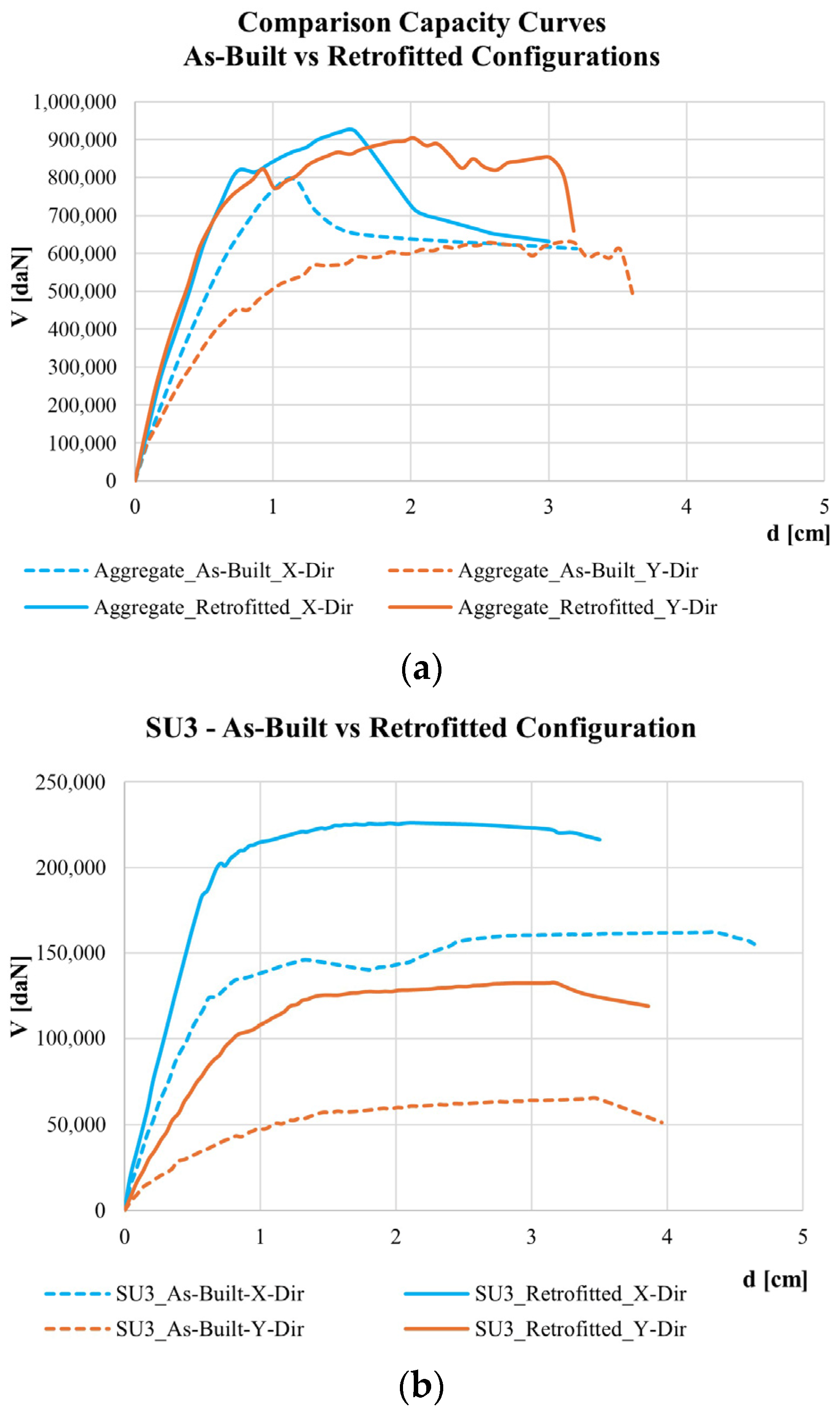
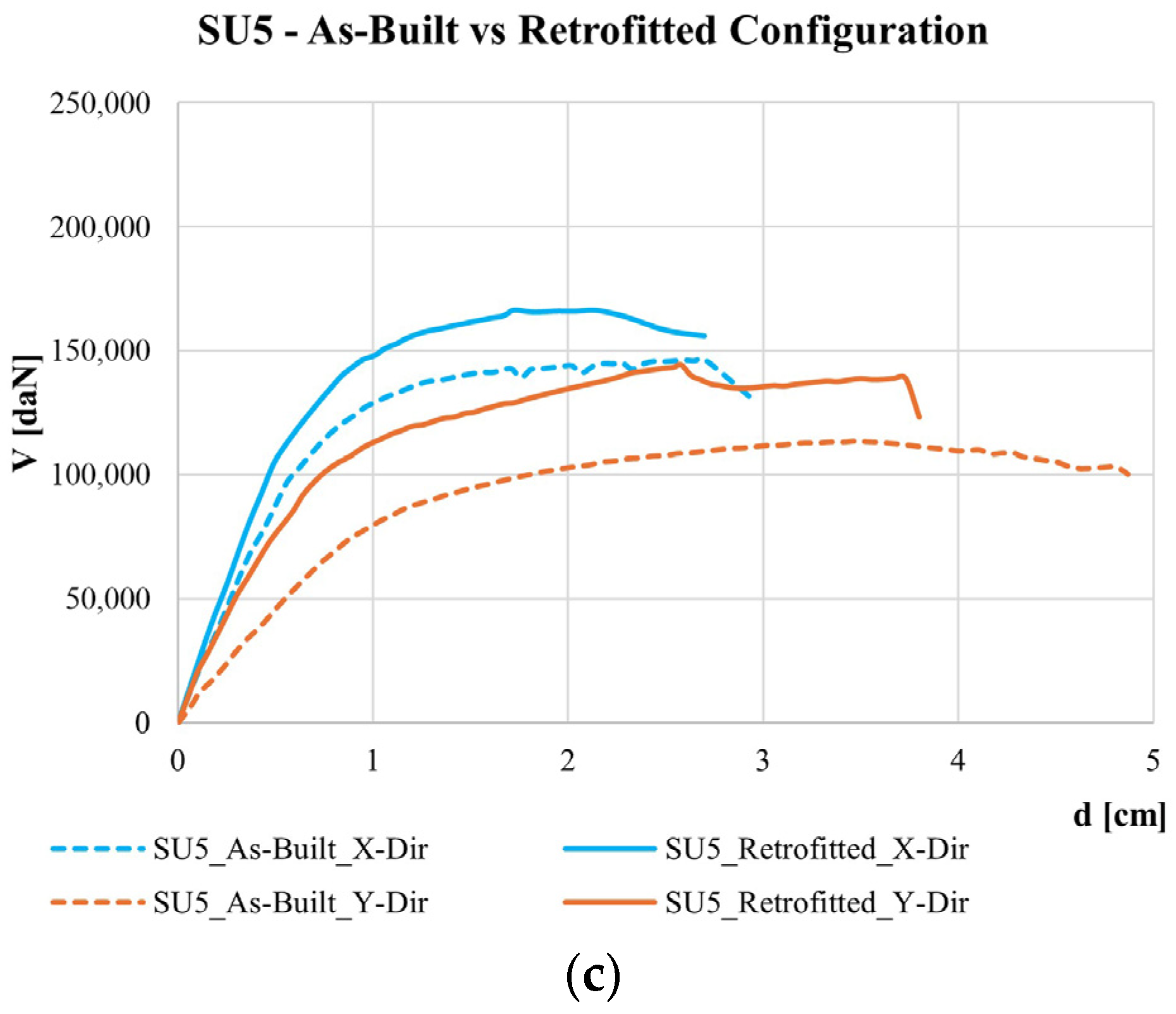
The divergences between the seismic performance of the entire compound and the isolated cell are further evidenced by the derivation of the capacity curves (base shear vs. top displacement) provided in Figure 6.
The aggregate model displays the attainment of significantly higher base shear values, as it accounts for the contribution of all SUs and therefore involves a much larger participating mass. At the same time, its ultimate displacements are more limited compared with those of the isolated units. This behavior is consistent with the presence of interaction effects within the aggregate: the mutual constraints imposed by adjacent SUs restrict deformation demand and promote a more globally coordinated response. In addition, the aggregate effect leads to a redistribution of seismic forces among units, with stiffer units attracting a larger portion of the base shear and more flexible units benefiting from lateral support.
In contrast, the capacity curves of the isolated units exhibit larger ultimate displacements, since the absence of neighbouring cells eliminates the lateral restraints that would otherwise limit deformation. This is particularly evident for the internal unit SU3, which—when analysed as isolated—reaches an ultimate displacement of nearly 5 cm in the X-direction, a value strongly influenced by the removal of the two adjacent SUs that would normally confine its motion. A similar behavior is observed for the heading unit SU5, which also attains an ultimate displacement of approximately 5 cm in the Y-direction. However, the influence of the aggregate effect is less pronounced in this case, as SU5 interacts structurally with only one adjacent unit. Consequently, the absence of the aggregate configuration alters its response to a lesser extent compared to SU3.
Finally, the continuous curves representing the retrofitted condition underline the significant increase in stiffness provided by the arrangement of the combined retrofitting system, which results in steeper initial branches and reduced lateral displacements for all of the investigated scenarios. These results highlight that the aggregate effect not only limits displacements but also enhances the global performance of the system by promoting cooperative behavior among the units. Understanding this effect is therefore essential for accurate seismic assessment and retrofit design of masonry complexes.
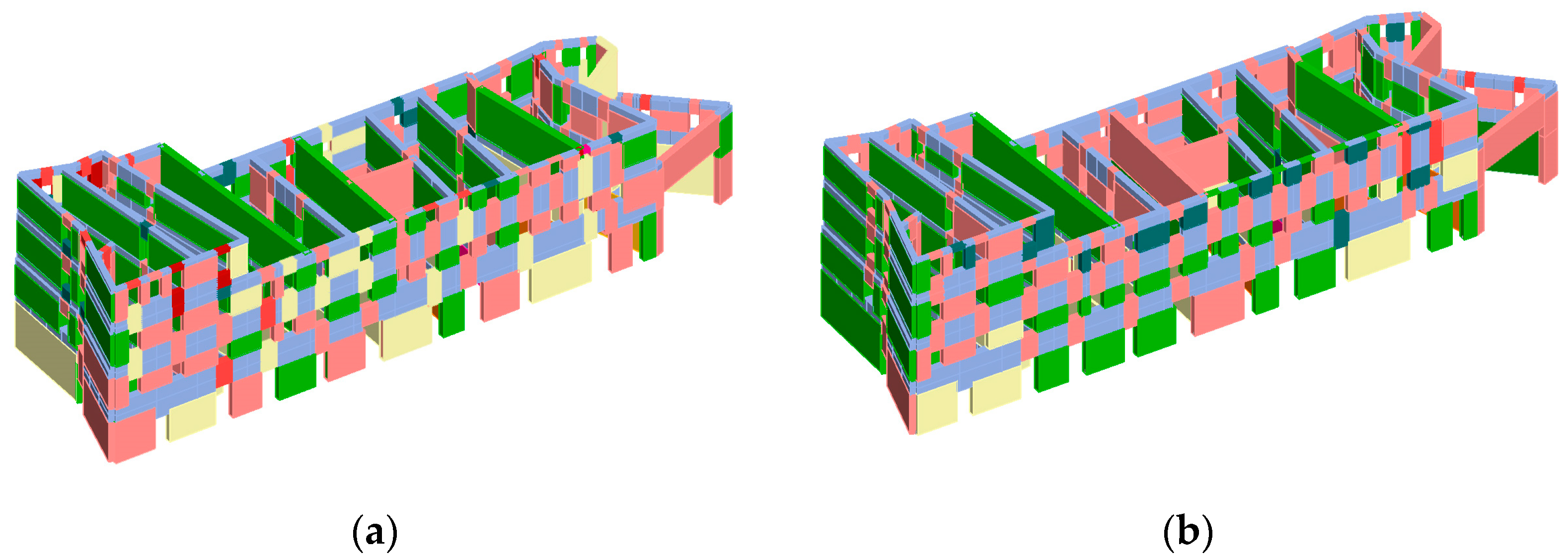
A qualitative comparison of the damage patterns observed in the numerical models highlights a significant difference between the as-built and the retrofitted configurations as depicted in Figure 7. In the unretrofitted condition, damage is mainly concentrated near the openings, where stress concentrations tend to activate brittle shear failure mechanisms (elements in yellow) and some plastic failure (element in pink) in the masonry piers. Conversely, the presence of the integrated seismic–energy strengthening system promotes a more uniform distribution of damage along the facades. The external retrofit system contributes to reducing concentrations of local stress and allows the structure to achieve a more global response, favouring the development of ductile mechanisms (element in pink) rather than brittle failures. This change in damage evolution represents a key benefit of the proposed intervention, as it enhances not only the global seismic capacity, but also the overall robustness of the structural response.
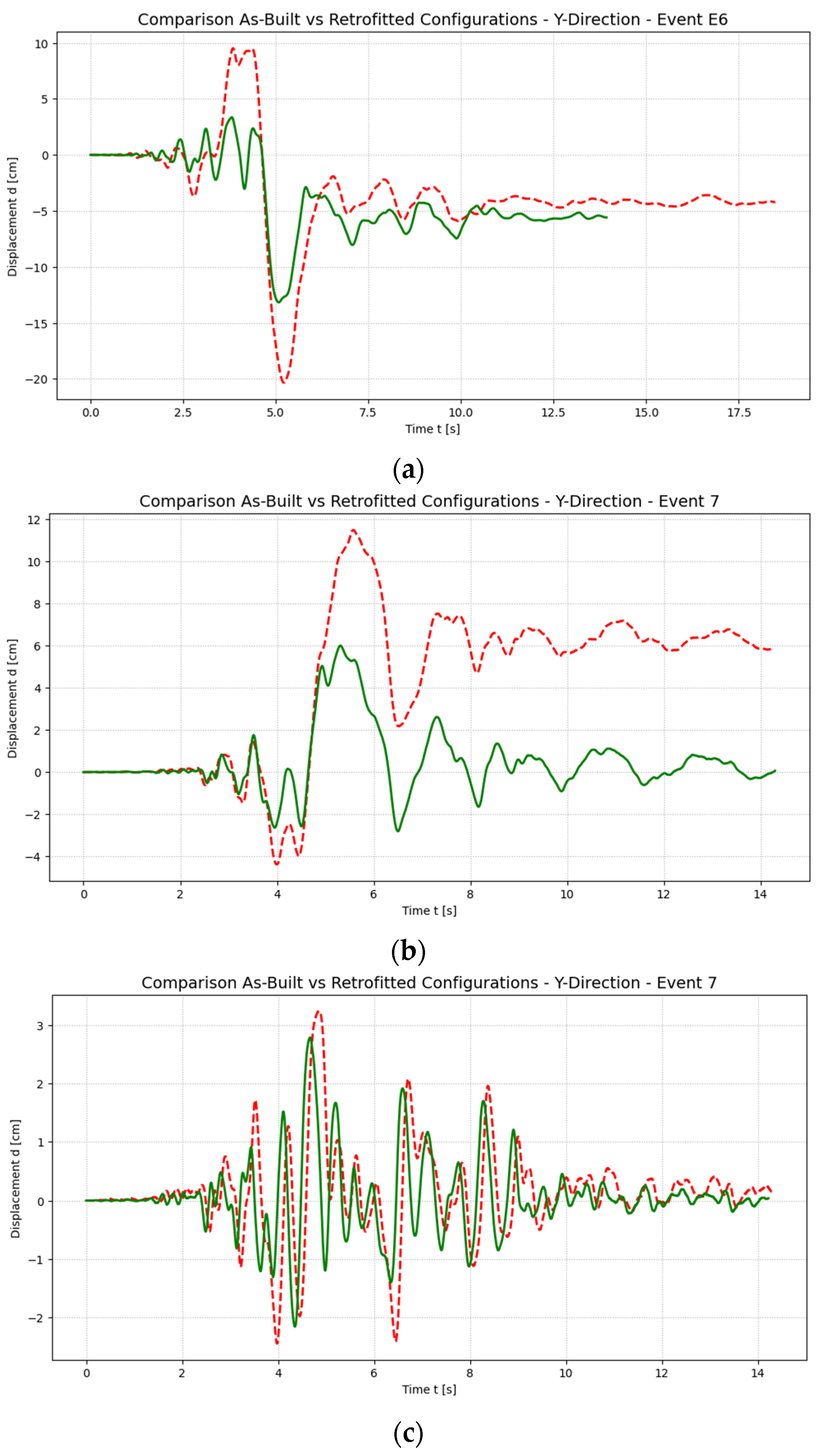
The outcomes obtained from the NLDAs are represented as displacement vs. time curves which provide a direct evaluation of the seismic response in the time domain for both the as-built and retrofitted configurations. The comparison was carried out for the entire aggregate and, in coherence with the NLSAs, also for the individual SUs, which were modelled as isolated buildings.
These curves are depicted in Figure 8, focusing attention on the structural response along the Y-direction, which represents the predominant axis of the masonry complex and the direction along which the retrofitting combined solution exhibits its predominant effect. The comparison of the displacement–time histories highlights the clear performance improvement of the retrofitted configuration (continuous green lines) compared to the as-built condition (dashed red lines).
Analysing both the behavior of the entire complex and that of the individual SUs evaluated as isolated (both internal and heading units), a systematic reduction of the maximum displacement peaks is observed. This phenomenon is particularly evident in the case of the internal structural unit.
Overall, these findings confirm that the application of the seismic-energy system has effectively increased the structure’s stiffness and energy dissipation capacity, mitigating critical deformations along the directions of greatest vulnerability and geometric development.

5.2. Thermal Performance Assessement by a Simplified Approach

The proposed retrofitting solution falls within the category of combined strengthening systems, as it simultaneously provides both seismic upgrading and energy performance improvement through a single intervention.
To demonstrate the benefits of this novel system from a thermal perspective, alongside the seismic performance evaluated by carrying out both nonlinear static and dynamic analysis, a simplified thermal assessment was conducted using the online tool Ubakus [38,39], which calculates the thermal transmittance of various building components.
Thermal transmittance, commonly referred to as the U-value, quantifies the amount of heat flow through a wall per unit area per unit temperature difference. It represents a key parameter for evaluating the thermal insulation performance of building envelopes.
For the as-built condition, a masonry wall approximately 60 cm thick, representative of the ground floor wall of a generic SU, was considered. The wall was assumed to be finished with mortar plaster applied on both the internal and external surfaces.
In the retrofitted configuration, the same masonry panel enhanced by the addition of the integrated seismic-energy coating layers described in Section 3 was considered. Within the sandwich panel, mineral wool insulation with a standard thickness of 100 mm was adopted.
The resulting U-value for the reinforced configuration was compared with the maximum allowable value prescribed by the Ministerial Decree of 26 June 2015, which establishes limit values for opaque vertical partitions depending on the climate zone.
The municipality of Visso, where the masonry aggregate is located, falls within climate zone E, characterized by a Heating Degree Days (HDD) range between 2100 and 3000. For this climate class, the regulation sets a maximum U-value equal to 0.28 W/m2K [40].
Table 6 presents a comparison of the two conditions.
The tool also provides an estimate of the heat capacity of the wall, which is significantly increased after the installation of the MIL15.s system. This improvement indicates a greater ability of the envelope to store thermal energy, thereby reducing heat losses and improving indoor comfort for occupants.
Furthermore, the retrofitted scenario does not exhibit risks of interstitial or surface condensation. This result is ensured by the proper design and positioning of the intermediate layers within the integrated system, which effectively prevent moisture accumulation and guarantee adequate hygrothermal performance.

6. Conclusions

This study investigates a retrofitting technique applied to a masonry complex in Visso, a small municipality in the Marche region heavily affected by the 2016 Central Italy seismic sequence. The research was carried out through the development of equivalent frame numerical models (FMEs), aiming to explore the influence of the so-called “aggregate effect” and to validate the effectiveness of an integrated retrofit strategy. Nonlinear analyses, both static and dynamic, were performed on the entire building complex as well as on two structural units: one internal and one at a corner (heading) position.
The proposed strengthening approach involves the application of the external seismic-energy coating system, MIL15.s, a technological solution combining an aluminium-alloy base-frame exoskeleton with insulating sandwich panels. The system was selected for its ability to simultaneously address structural and energy deficiencies, providing enhanced seismic performance while reducing thermal losses. The use of aluminium alloy ensures a lightweight intervention that does not increase seismic masses and, due to its high recyclability, satisfies contemporary environmental sustainability standards.
Nevertheless, the applicability of this retrofitting system is mainly limited to non-monumental historic masonry buildings, as the installation of external coating solutions may be constrained in the presence of architectural or cultural protection requirements.
Results from the numerical simulations highlighted significant differences between modelling the entire complex and individual units. Analyses showed that neglecting mechanical interactions between adjacent units leads to unrealistic estimations of structural response. In particular, isolated models tend to overestimate ultimate displacement capacity, as they do not benefit from the lateral confinement and force redistribution provided by neighbouring buildings. This underscores the importance of modelling historical centres as complex aggregates to achieve reliable assessments of global stiffness and safety.
Regarding the effectiveness of the intervention, comparisons between pre- and post-retrofit conditions yielded highly positive results. Nonlinear static analyses recorded a systematic increase in the seismic safety index, αSLV, of at least 0.1 across all scenarios, fully meeting regulatory requirements for seismic improvement. These results were further confirmed by nonlinear dynamic analyses, whose displacement–time histories provided a detailed understanding of structural behavior, particularly along the Y-direction, the main longitudinal axis of the complex. The displacement–time graphs showed a marked reduction in peak displacements compared to the as-built condition.
Overall, the intervention effectively mitigated seismic vulnerability, confirming its suitability as an optimal solution for preserving and enhancing historic masonry heritage.

Author Contributions

Conceptualization, G.L. and A.F.; methodology, G.L. and A.F.; software, G.L.; validation, G.L. and A.F.; formal analysis, G.L.; investigation, G.L.; resources, A.F.; data curation, G.L. and A.F.; writing—original draft preparation, G.L.; writing—review and editing, G.L. and A.F.; visualization, G.L. and A.F.; supervision, A.F.; project administration, A.F.; funding acquisition, A.F. All authors have read and agreed to the published version of the manuscript.

Funding

This research received no external funding.

Data Availability Statement

The original contributions presented in this study are included in the article. Further inquiries can be directed to the corresponding author.

Acknowledgments

The authors would like to thank TM Group S.r.l. for the implementation and production of the presented retrofit system. Authors also acknowledge the DPC-ReLUIS 2024-2026 research project (WP4 research line) for the financial support of the current research activity.

Conflicts of Interest

The authors declare no conflicts of interest.

Abbreviations

The following abbreviations are used in this manuscript:
SUStructural Units
NLSAsNonlinear Static Analyses
NLDAsNonlinear Dynamic Analyses

References

  1. Grillanda, N.; Valente, M.; Milani, A.; Chiozzi, A. Advanced numerical strategies for seismic assessment of historical masonry aggregates. Eng. Struct. 2020, 212, 110441. [Google Scholar] [CrossRef]
  2. Formisano, A.; Chieffo, N. Seismic Damage Scenarios Induced by Site Effects on Masonry Clustered Buildings: A Case Study in South Italy. Int. J. Arch. Herit. 2022, 17, 262–283. [Google Scholar] [CrossRef]
  3. Angiolilli, M.; Lagomarsino, S.; Degli Abbati, S. Seismic fragility assessment of existing masonry buildings in aggregate. Eng. Struct. 2021, 247, 113218. [Google Scholar] [CrossRef]
  4. Di Trapani, F.; Villar, S.; Di Benedetto, M.; Petracca, M.; Camata, G. Seismic response of unreinforced masonry building aggregates: Investigation on the “aggregate-effect” based on an elementary building aggregate. Eng. Struct. 2024, 316, 118301. [Google Scholar] [CrossRef]
  5. Pinchuk, N.; Castellano, A.; Micello, D.; Camassa, D.; Diaferio, M.; Fraddosio, A. Dynamic Identification of the Collapse Mechanisms of a Masonry Arch. In Proceedings of the 2024 IEEE International Workshop on Metrology for Living Environment (MetroLivEnv 2024), Chania, Crete, Greece, 12–14 June 2024; IEEE: New York, NY, USA, 2024; pp. 128–133. [Google Scholar]
  6. Longobardi, G.; Formisano, A. Influence of structural-geological features and knowledge levels on the seismic vulnerability of masonry clustered buildings: A case study in Mirandola (Italy). Bull. Earthq. Eng. 2025. [Google Scholar] [CrossRef]
  7. Ruggieri, S.; Liguori, F.S.; Leggieri, V.; Bilotta, A.; Madeo, A.; Casolo, S.; Uva, G. An archetype-based automated procedure to derive global-local seismic fragility of masonry building aggregates: META-FORMA-XL. Int. J. Disaster Risk Reduct. 2023, 95, 103903. [Google Scholar] [CrossRef]
  8. Pavlikov, A.; Pinchuk, N.; Kachan, T. Strength of Masonry Indirectly Reinforced by Expanded Steel Sheets. Lect. Notes Civ. Eng. 2022, 181, 303–311. [Google Scholar]
  9. Davino, A.; Meglio, E.; Formisano, A. Lime-Based Plaster Reinforced with Hemp Braids as Sustainable Building Product. Architecture 2022, 2, 135–156. [Google Scholar] [CrossRef]
  10. Pertile, V.; De Stefani, L.; Scotta, R. Development and characterization of a system for the seismic and energy retrofit of existing buildings. Procedia Struct. Integr. 2018, 11, 347–354. [Google Scholar] [CrossRef]
  11. Davino, A.; Longobardi, G.; Meglio, E.; Dallari, A.; Formisano, A. Seismic energy upgrading of an existing brick masonry building by a cold—Formed steel envelope system. Buildings 2022, 12, 1918. [Google Scholar] [CrossRef]
  12. European Commission. The European Green Deal—Communication from the Commission to the European Parliament, the European Council, the Council, the European Economic and Social Committee, and the Committee of the Regions. Brussels: European Commission. 2019. Available online: https://eur-lex.europa.eu/legal-content/EN/TXT/?uri=CELEX:52019DC0640 (accessed on 3 November 2025).
  13. European Commission. Fit for 55: Delivering the EU’s 2030 Climate Target on the Way to Climate Neutrality. European Commission. 2021. Available online: https://www.eesc.europa.eu/en/our-work/opinions-information-reports/opinions/fit-55-delivering-eus-2030-climate-target-way-climate-neutrality (accessed on 3 November 2025).
  14. Heat Roadmap Europe. Heating and Cooling Facts and Figures. 2017. Available online: https://heatroadmap.eu/wp-content/uploads/2019/03/Brochure_Heating-and-Cooling_web.pdf (accessed on 3 November 2025).
  15. Almeida, M.; Ascione, F.; Iaccheo, A.; Iovane, T.; Mastellone, M. Towards the Necessary Decarbonization of Historic Buildings: A Review. Energies 2025, 18, 502. [Google Scholar] [CrossRef]
  16. Available online: https://www.ecosism.com/moduli/geniale/ (accessed on 3 November 2025).
  17. Available online: https://sismacoat.it/ (accessed on 3 November 2025).
  18. Available online: https://duosystem.eu/ (accessed on 3 November 2025).
  19. Available online: https://www.betonwood.com/betontherm-fiber.html (accessed on 3 November 2025).
  20. Available online: https://www.progettosisma.it/product (accessed on 3 November 2025).
  21. Schiavoni, M.; Giordano, E.; Roscini, F.; Clementi, F. Advanced numerical insights for an effective seismic assessment of historical masonry aggregates. Eng. Struct. 2023, 285, 115997. [Google Scholar] [CrossRef]
  22. Wang, P.; Milani, G. Seismic vulnerability and prediction of masonry aggregates: Iterative Finite element Upper Bound limit analysis approximating nos tensile resistance. Eng. Struct. 2023, 293, 116595. [Google Scholar] [CrossRef]
  23. Cima, V.; Tomei, V.; Grande, E.; Imbimbo, M. The Influence of the Aggregate Configuration on the Seismic Assessment of Unreinforced Masonry Buildings in Historic Urban Areas. Sustainability 2016, 16, 4172. [Google Scholar] [CrossRef]
  24. Available online: http://zonesismiche.mi.ingv.it/mappa_ps_apr04/italia.html (accessed on 13 November 2025).
  25. Available online: https://emergeo.ingv.it/emergenze-concluse/2016-terremoto-del-centro-italia (accessed on 13 November 2025).
  26. Ministerial Decree of Public Works. New Technical Codes for Constructions, Official Gazette of the Italian Republic n. 42. 2018. Available online: https://www.gazzettaufficiale.it/eli/id/2018/2/20/18A00716/sg (accessed on 3 November 2025).
  27. Ministerial Circular. Instructions for the Application of the “New Technical Code for Constructions”. Official Gazette of the Italian Republic. 2019. Available online: https://www.gazzettaufficiale.it/eli/id/2019/02/11/19A00855/sg (accessed on 3 November 2025).
  28. UNI EN 338:2004; Structural Timber—Strength Classes. European Committee for Standardization (CEN): Brussels, Belgium, 2004.
  29. Available online: https://www.tmgroupsrl.eu/sistemi-per-ledilizia/ (accessed on 13 June 2025).
  30. CNR-DT 208/2011; Instructions for the Design, Execution, and Control of Aluminium Structures. National Research Council: Ottawa, ON, Canada, 2011.
  31. EN 1999-1-1:2003; Eurocode 9—Design of Aluminium Structures. European Committee for Standardization: Brussels, Belgium, 2005.
  32. Available online: https://international-aluminium.org/ (accessed on 17 November 2025).
  33. Available online: https://www.cial.it/ (accessed on 17 November 2025).
  34. S.T.A. DATA. 3 Muri Program 14.2.0. Available online: http://www.stadata.com (accessed on 3 November 2025).
  35. Davies, M.J. Developments in stressed skin design. Thin-Walled Struct. 2006, 44, 1250–1260. [Google Scholar] [CrossRef]
  36. Available online: https://itaca.mi.ingv.it/ItacaNet_40/#/rexel (accessed on 2 September 2025).
  37. Available online: https://itaca.mi.ingv.it/ItacaNet_40/documentation_data/rexelweb/ITACA_REXELweb_manual_ENG_ITA.pdf (accessed on 2 September 2025).
  38. Available online: https://www.ubakus.de/u-wert-rechner/? (accessed on 2 September 2025).
  39. Bocan, D.; Bocan, C.; Keller, A.; Gruin, A. Analysis of Thermal Rehabilitation and Seismic Strengthening Solutions Suitable for Heritage Structures. Sustainability 2024, 16, 5369. [Google Scholar] [CrossRef]
  40. Ministero dello Sviluppo Economico. Decreto 26 Giugno 2015—Requisiti Minimi di Prestazione Energetica degli Edifici. Gazzetta Ufficiale della Repubblica Italiana, Serie Generale n. 159. 2015. Available online: https://www.gazzettaufficiale.it/eli/id/2015/07/15/15A05200/s (accessed on 3 November 2025). (In Italian)
Figure 1. Location of Visso on the Italian territory and view of its historic centre.
Buildings 16 01208 g001
Figure 2. Seismic risk map of the Marche region of Italy. White circle indicates the approximately location of the city of Visso.
Buildings 16 01208 g002
Figure 3. (a) Ground floor layout with the identification of the SUs. (b) Main front view of the aggregate. (c) Cross-section. (d) View of the main façade before the earthquake.
Buildings 16 01208 g003
Figure 4. View of the MIL 15.s system with its components.
Buildings 16 01208 g004
Figure 5. Entire aggregate in (a) as-built configuration (main façade) and (b) retrofitted configuration (main façade); (c) SU3 (as-built configuration); and (d) SU5 (as-built configuration).
Buildings 16 01208 g005
Figure 6. Comparison of capacity curves: (a) entire aggregate; (b) SU3; and (c) SU5. (Legend: dotted lines: as-built configuration; continuous lines: retrofitted configuration; orange lines: X-direction, blue lines: Y-direction).
Buildings 16 01208 g006aBuildings 16 01208 g006b
Figure 7. Comparison of the damage pattern on the three-dimensional model representing the entire building complex: (a) as-built configuration; (b) retrofitted configuration.
Buildings 16 01208 g007
Figure 8. NLDA results: (a) entire aggregate; (b) SU3; and (c) SU5. (Legend: dotted red lines: as-built configuration; continuous green lines: retrofitted configuration).
Buildings 16 01208 g008
Table 1. Mechanical properties for masonry of the aggregate cells.
Young Modulus
E
Shear Modulus
G
Compressive Strength
fm
Shear Strength
τ
Weight
w
[N/mm2][N/mm2][N/mm2][N/cm2][kN/m3]
17405802.605.6021
Table 2. Mechanical properties of timber beams.
Charact. Bending Strength
fm,k
Charact. Tensile Strength (Parallel to the Grain)
ft,0,k
Young Modulus (Parallel to the Grain)
E0,mean
Shear Modulus
G
Density
w
[N/mm2][N/mm2][N/mm2][N/mm2][kN/m3]
3018100.605.4
Table 3. Mechanical properties of the retrofit system aluminium alloy profiles.
Charact. Value of 0.2-Proof Strength
f0.2
Ultimate Tensile Strength
fu
Failure StrainBuckling ClassDurability Class
[N/mm2][N/mm2][%][-][-]
1501908AB
Table 4. The seven spectrum-compatible earthquakes selected for seismic analysis.
Event No.StationMw
1Pasciano Amatrice6.6
2L’Aquila6.1
3Castelluccio di Norcia6.6
4Castel Sant’Angelo Sul Nera6.6
5Mirandola 6.1
6Medolla6.0
7Mirandola6.0
Table 5. Results of NLSAs on the entire aggregate and on the two SUs.
Entire Aggregate
NrEarthquake DirectionSeismic LoadEccentricity [cm]As-Built Conf. αSLVRetrofitted Conf. αSLVΔ [%]
16−XStatic Forces−267.020.3280.49952
23−YStatic Forces136.630.2650.47579
SU3
NrEarthquake DirectionSeismic LoadEccentricity [cm]As-Built Conf. αSLVRetrofitted Conf. αSLVΔ [%]
16−XStatic Forces−67.500.4110.46813
23−YStatic Forces90.400.2770.40044
SU5
NrEarthquake DirectionSeismic LoadEccentricity [cm]As-Built Conf. αSLVRetrofitted Conf. αSLVΔ [%]
16−XStatic Forces−91.500.4660.51510
23−YStatic Forces65.790.4300.50316
Table 6. Comparison of thermal analysis scenarios.
ScenarioU-Value [W/m2K]Heat Capacity [kJ/m2K]
As-built1.286577
Retrofitted0.2801300
Disclaimer/Publisher’s Note: The statements, opinions and data contained in all publications are solely those of the individual author(s) and contributor(s) and not of MDPI and/or the editor(s). MDPI and/or the editor(s) disclaim responsibility for any injury to people or property resulting from any ideas, methods, instructions or products referred to in the content.