Article

Seismic Performance of Concentrically Braced Steel Frames Equipped with Novel Self-Centering Dual-Stage Yielding Buckling-Restrained Braces

1
School of Civil and Hydraulic Engineering, Lanzhou University of Technology, Lanzhou 730050, China
2
School of Environment and Urban Construction, Lanzhou City University, Lanzhou 730070, China
*
Author to whom correspondence should be addressed.
Buildings 2026, 16(5), 960; https://doi.org/10.3390/buildings16050960
Submission received: 20 January 2026 / Revised: 13 February 2026 / Accepted: 26 February 2026 / Published: 28 February 2026
(This article belongs to the Section Building Structures)

Abstract

Conventional buckling-restrained braces provide stable and efficient hysteretic energy dissipation but lack a recentering mechanism and adequate deformation capacity, which may result in significant residual deformations after strong earthquakes. Conventional self-centering braces reduce residual deformation but often provide limited energy dissipation under large seismic demands. To address these complementary limitations, a novel self-centering dual-stage yielding buckling-restrained braces is proposed. The device uses a two-stage core. A shape memory alloy first-stage core provides recentering. A low-yield-point steel second-stage core provides supplemental energy dissipation. An activation-displacement mechanism controls staged engagement of the two cores. Experimental tests validate the feasibility of the proposed configuration and confirm its stable hysteretic behavior and reliable recentering performance. A six-story concentrically braced steel frame is subsequently modeled in OpenSees, and nonlinear time-history analyses are performed to evaluate the seismic response of the system. Under an equal initial-stiffness design criterion, the seismic performance of frames equipped with the proposed brace is systematically compared with those incorporating a conventional self-centering brace and a conventional buckling-restrained brace. The numerical results indicate that the proposed system achieves enhanced control of interstory drift, mitigates weak-story behavior, and effectively reduces residual deformation under different seismic hazard levels while promoting a more uniform distribution of deformation along the structural height. Furthermore, a comprehensive parametric study is carried out to clarify the influence of key design parameters on displacement response and recentering performance, providing practical guidance for the seismic design and engineering application of the proposed brace.

1. Introduction

Steel frame structures are widely regarded as having excellent seismic performance due to their low self-weight, good ductility, high strength, and favorable post-earthquake repairability [1,2]. However, observations from actual earthquake damage indicate that, under strong seismic actions, steel frame buildings may still suffer severe damage or even collapse. In the Northridge Earthquake in the United States, a post-earthquake investigation of 2066 steel buildings found that connection damage occurred in 70% of the structures [3]. In the Hanshin Earthquake in Japan, nearly one-quarter of steel buildings could not be restored and had to be partially or entirely demolished [4]. In the Wenchuan Earthquake in China, post-earthquake surveys showed that although steel frames generally exhibited better seismic performance than reinforced concrete structures, damage still occurred at the connections of long-span steel structures [5]. After the Christchurch Earthquake in New Zealand, multiple steel frame–bracing systems exhibited brace connection failures and brace buckling failures, and collapse of the steel frame–bracing systems was also observed. Although most steel frames did not collapse, they were severely damaged and rendered unserviceable. The reconstruction cost of the central business district alone reached as high as 40 billion New Zealand dollars [6,7].
Concentrically braced steel frames constitute a lateral-force-resisting structural system. Compared with moment-resisting frames, concentrically braced steel frames possess higher lateral stiffness, and the incorporation of concentrically braced members in the frame can effectively control plastic deformation under seismic excitation [8,9]. The buckling-restrained brace (BRB), owing to its favorable energy-dissipation capacity and buckling-restraining characteristics, has been widely applied in concentrically braced steel frames [10,11]. However, the conventional BRB generally dissipates energy through yielding of a single core plate, and under strong earthquakes it may suffer from low post-yield stiffness, damage to the energy-dissipating core, the absence of a self-centering mechanism, and large residual deformations [12,13,14]. Compared with the BRB, the self-centering brace (SCB) can provide an effective recentering capability for structures, but its energy-dissipation capacity is relatively limited [15,16,17], and certain limitations remain for applications in high-rise buildings and in regions of low seismic intensity [18]. Therefore, to improve the overall seismic performance of structures, researchers have proposed self-centering energy-dissipating braces [19] and multi-stage yielding buckling-restrained braces [20,21,22]. Self-centering energy-dissipating braces aim to enhance both recentering and energy dissipation through the coordinated use of self-centering components and energy-dissipating components [23,24]. Self-centering systems are commonly realized using prestressed tendons or shape memory alloy (SMA), which provide the recentering capability [25,26,27]. Nevertheless, the applicability of prestressed tendons is constrained by their limited deformation capacity and potential prestress loss [28]. By contrast, owing to its superelasticity and favorable manufacturability, SMA is often fabricated into self-centering components such as wires [29], cables [26], bars [30], disc springs [31], and bolts [32]. However, these components typically resist only tensile or compressive loads, and achieving stable self-centering behavior often requires a complex force-transfer mechanism [33]. Multi-stage yielding buckling-restrained braces can realize staged yielding by adopting core materials with different yield strains, controlling the length of the core segment, or introducing frictional mechanisms [34,35,36]. Most existing designs in the literature are dual-stage yielding, whereas three-stage or higher-stage yielding configurations are relatively rare [37,38,39]. Such braces primarily rely on the additional stiffness provided by the second-stage core to restrain further deformation, thereby indirectly reducing residual deformation; consequently, these devices do not provide a self-centering capability [40,41].
To address the above issues, a novel self-centering dual-stage yielding buckling-restrained brace (SCDYB) with a simple configuration and convenient assembly is proposed. The proposed device integrates and further improves upon the advantages of the two mature bracing systems discussed above, thereby providing both recentering capability and energy-dissipation capacity. Based on the OpenSees platform (Official website: https://opensees.berkeley.edu/), three concentrically braced steel frame models incorporating SCB, BRB, and SCDYB are established separately, and nonlinear time-history analyses are conducted to compare the seismic performance of the three bracing systems. In addition, a parametric study is performed on the SCDYB to evaluate the effects of key parameters on the seismic performance of steel frames equipped with the SCDYB.

2. Configuration and Mechanical Characteristics of the SCDYB

2.1. Device Configuration

The novel self-centering dual-stage yielding buckling-restrained brace, shown in Figure 1, consists of an energy-dissipation system and a restraining system. The energy-dissipation system comprises end plates, connecting plates, a filler connecting plate, two first-stage core plates made of shape memory alloy (SMA) and two second-stage core plates fabricated from low-yield-point steel LY160. All materials and components in this study were processed and provided by Gansu Zhuotong Electromechanical Equipment Co., Ltd., Lanzhou, China. The restraining system comprises restraining plates, stopper plates, separator plates, inner filler plates, and outer filler plates. All components are assembled using bolted connections. The end plates are connected to the steel frame. On both sides of each end plate, the connecting plates link the core plates on the two sides, and the filler connecting plate is placed between the two sets of core plates. These components together form the energy-dissipation system of the SCDYB. The remaining components constitute the restraining system, which limits the lateral deformation of the core plates and suppresses buckling while guiding the end plates to carry axial forces.
As illustrated in Figure 1, the brace can be decomposed along its longitudinal axis into five parts. The first-stage core plates are made of NiTi shape memory alloy, which can exhibit flag-shaped hysteretic behavior through reverse phase transformation; compared with conventional steel materials, it possesses a higher recoverable strain capacity, thereby providing the steel frame with recentering capability through the device. The second-stage core plates are fabricated from low-yield-point steel LY160 and mainly provide energy dissipation. To ensure the stability of the axial force-transfer path of the core plates and to prevent buckling of non-energy-dissipating components such as the restraining elements, all remaining components are made of Q355 steel. Because the non-core components exhibit relatively high stiffness, the brace can be repaired after an earthquake by replacing only the damaged core plates. This repair is feasible when the restraining system and the connecting components sustain no significant damage. It should be noted that an activation displacement (gap) is reserved along the axial direction of the second-stage core plates; before the gap closes, the second-stage core plates essentially do not participate in force resistance. Once the axial deformation of the brace reaches the prescribed activation displacement, the second-stage core plates come into contact with the stopper plate (or the inner filler plate) and then begin to carry load. By adjusting the magnitude of the activation displacement, this design enables flexible control of the engagement timing of the second-stage core plates, thereby achieving an optimized balance between the recentering capability and the energy-dissipation performance while accounting for both economy and safety.

2.2. Working Mechanism

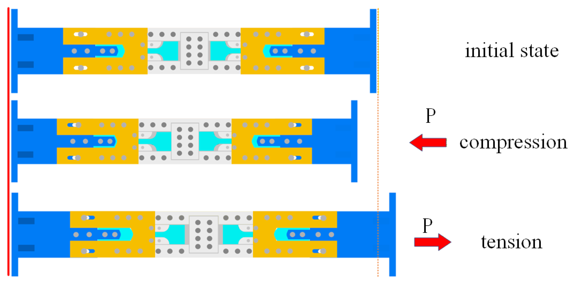
The proposed SCDYB follows the same load-transfer concept as conventional dual-stage yielding BRB, in which energy dissipation is achieved through direct axial tension–compression of the core plates. Two features distinguish the SCDYB: (1) Both the first-stage and second-stage cores consist of two discontinuous plate segments arranged in series, which enables replacement of individual core segments; the first-stage core plates are made of SMA. (2) The second-stage core adopts an asynchronous activation mechanism. An activation displacement is provided and relative sliding between plates is allowed, such that engagement of the second-stage core is intentionally delayed.
Figure 2 illustrates three working states of the SCDYB and highlights the engagement process of the second-stage core. In the initial state, the two-stage cores are essentially inactive and the brace remains in equilibrium. Under compression, an axial displacement is imposed by the end plates. The first-stage core engages immediately, while the second-stage core remains inactive until the prescribed axial displacement is reached and a complete load path is established. Thereafter, with further deformation, the second-stage core yields and dissipates energy. A similar mechanism applies under tension. Overall, the first-stage SMA core mainly provides the recentering capacity and contributes limited hysteretic energy dissipation at relatively large deformation demands. The activation displacement reduces the energy-dissipation contribution of the second-stage core at small-to-moderate deformation levels. Therefore, the second-stage core is fabricated from low-yield-point steel LY160 to promote early yielding and enhance the overall energy-dissipation capacity of the SCDYB.

2.3. Mechanical Model and Control Parameters

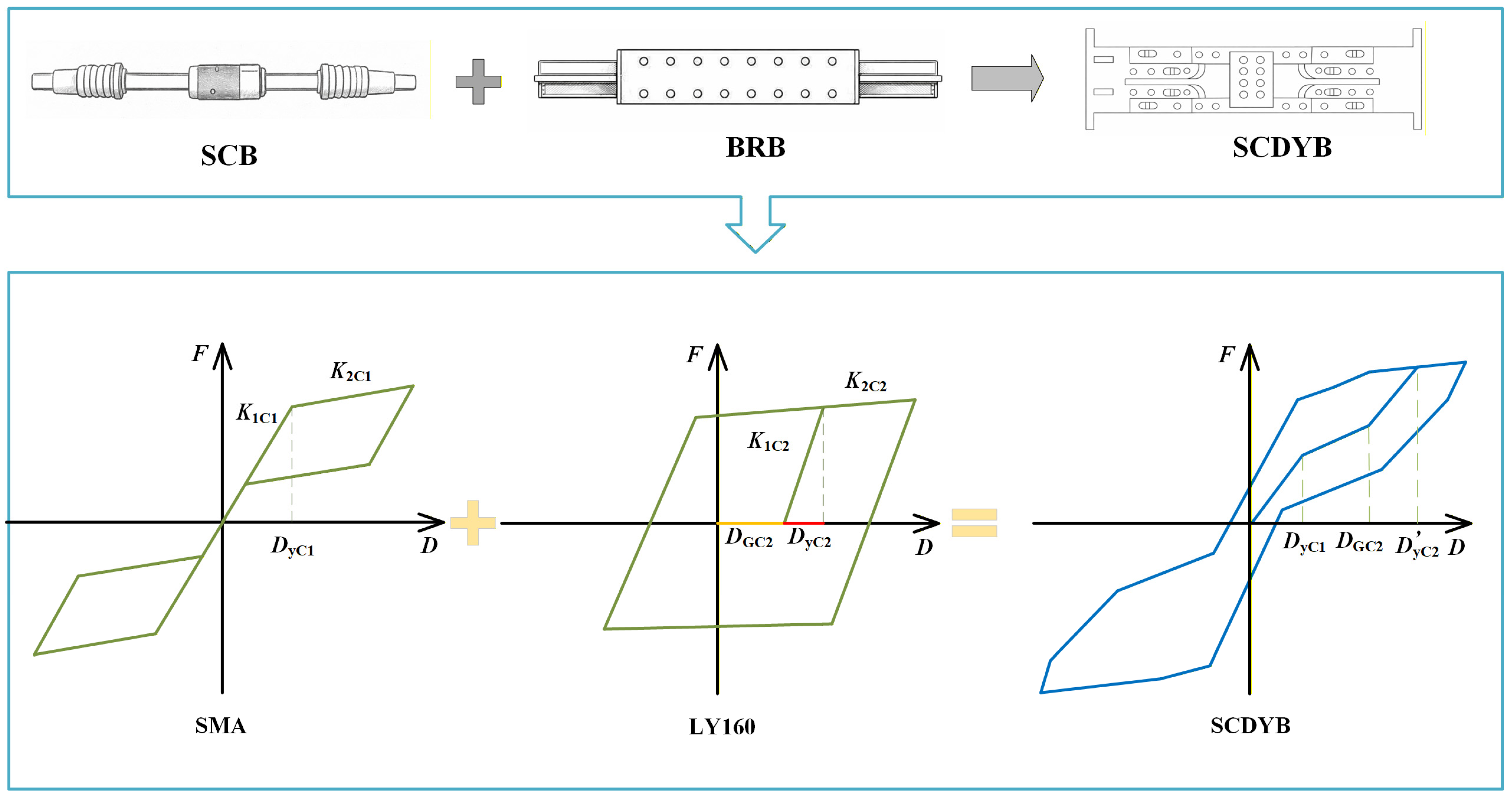
As shown in Figure 3, SCB mainly achieves the resetting function through reset components such as disc springs to reduce residual deformation after an earthquake. The mechanical model is a flag-shaped multilinear model. BRB, on the other hand, primarily dissipates seismic energy through its energy-dissipating core to reduce the seismic response of the structure. The mechanical model for BRB is a bilinear model. Previous studies have established and validated restoring-force models for conventional SCB and BRB in a relatively systematic manner. SCDYB is based on these two types of devices, and through modifications in the structural configuration, self-centering and energy-dissipating components are introduced. Therefore, the core energy-dissipation segment of the SCDYB consists of a self-centering core and an energy-dissipating core, which results in dual-stage yielding behavior. Unlike traditional braces, SCDYB integrates self-centering and energy-dissipation functions, thus providing an optimized seismic performance. Based on its mechanical mechanism, the hysteretic model of the SCDYB can be approximately represented as the superposition of (i) a flag-shaped multilinear model for SCB and (ii) a bilinear model for BRB. It should be noted that an activation displacement is introduced for the second-stage core, which shifts the initial loading point of its bilinear model along the displacement axis. Consequently, the force-resisting response initiates away from the origin, as schematically shown in Figure 3.
To rationally define the key parameters of the SCDYB in steel frames, a dimensionless formulation is adopted in this study. Referring to Figure 3, the ratio of the yield displacement of the first-stage core plate of the SCDYB to the yield displacement of the steel frame, denoted by α, is defined in Equation (1). The ratio of the initial stiffness of the SCDYB to the initial stiffness of the steel frame, denoted by β, is defined in Equation (2).
α = D yC 1 D yF
β = K 1 C 1 K F
where K1C1, K2C1, and DyC1 denote the initial stiffness, post-yield stiffness, and yield displacement of the first-stage core, respectively. DyF denotes the yield displacement of the steel frame, and KF denotes the initial stiffness of the steel frame.
When defining the key parameters of the SCDYB components, the first-stage core plate is taken as the reference unit, and the corresponding basic parameters of the second-stage core plate and the activation displacement are defined accordingly. This allows a dimensionless parameter set to be established to relate the SCDYB components to the steel frame. The yield-displacement ratio of the second-stage core plate to the first-stage core plate, denoted by λyC, is defined in Equation (3). The activation-displacement ratio of the second-stage core plate to the yield displacement of the first-stage core plate, denoted by λGCB, is defined in Equation (4). The initial-stiffness ratio between the first-stage and second-stage core plates, denoted by ρe, is defined in Equation (5), as follows:
λ yC = D y C 2 D y C 1
λ GCB = D GC 2 D yC 1
ρ e = K 1 C 2 K 1 C 1
where K1C2, K2C2, and DyC2 denote the corresponding parameters for the second-stage core, and DGC2 denotes the activation displacement of the second-stage core. Note that, due to the activation displacement, the second-stage yield displacement of the SCDYB device, denoted by D y C 2 , is not equal to the yield displacement of the second-stage core plate DyC2. Their relationship depends on the activation displacement and can be expressed as D y C 2 = D GC 2 + D yC 2 .

3. Structural System and Analytical Model

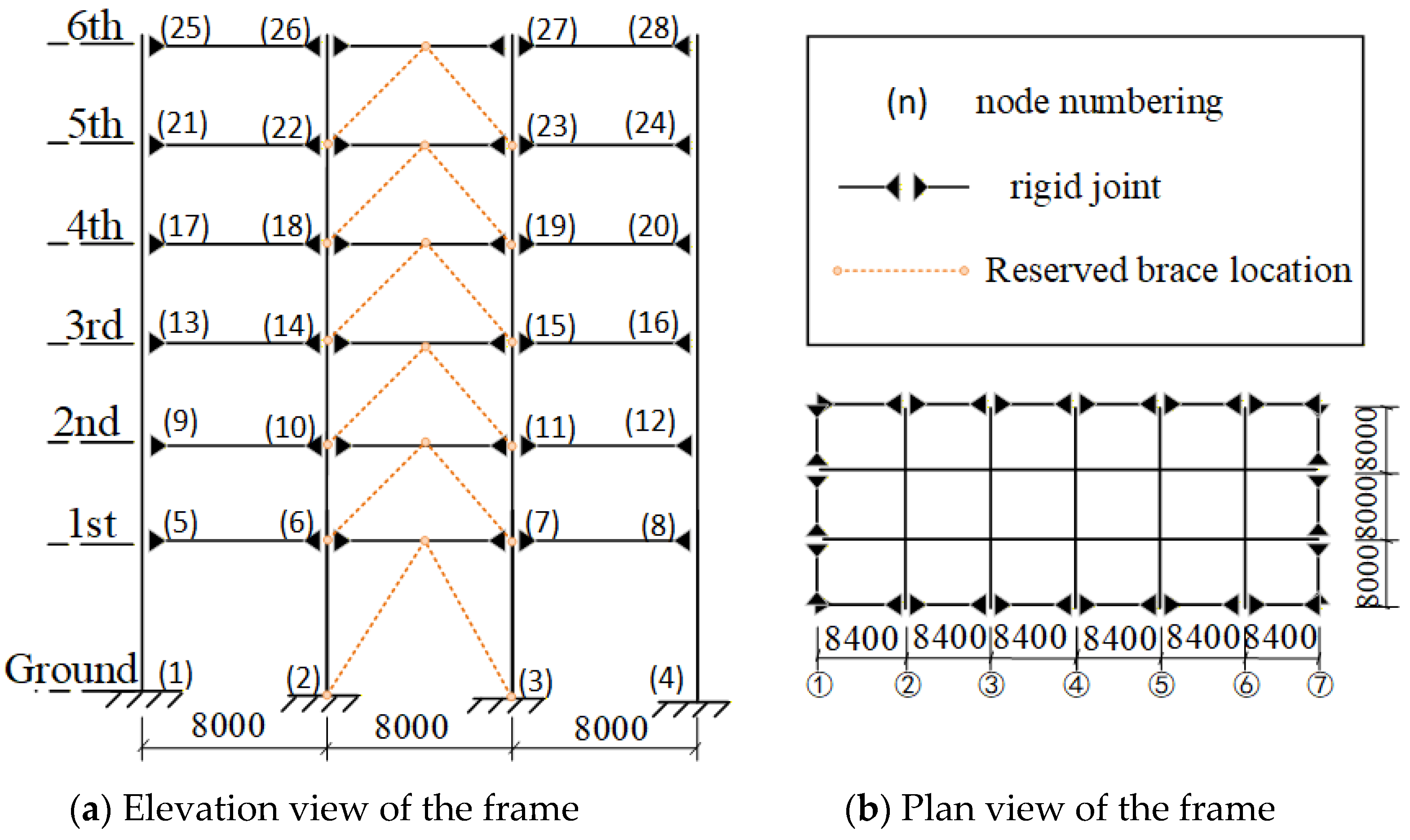
The six-story steel frame presented in Ref. [42] is adopted as the analytical model and serves as the benchmark structure for evaluating the seismic response mitigation of braced steel frame systems; the braces are arranged in the middle bay in an inverted V configuration. The elevation and plan of the structure are presented in Figure 4. All beam-to-column connections are assumed to be rigid. The columns are square hollow sections, and the beams are H-shaped steel sections. Both beams and columns are made of Q345 steel. The typical story height is 4 m, and the first-story height is 5 m. Member sections are summarized in Table 1, and the plan layout is shown in Figure 4b. Only the transverse response is considered. Owing to structural symmetry, the 2D planar frame on Gridline 4 is adopted for analysis, following Ref. [42]. The six-story frame was designed in accordance with the Chinese Code for Seismic Design of Buildings (GB 50011—2010), and the seismic design parameters are as follows: seismic fortification intensity of 8, design basic ground acceleration of 0.20 g, Seismic Group 1, Site Class III, site characteristic period of 0.45 s, and seismic fortification category B [43].
Considering the infill walls and the self-weight of beams and columns, the standard values of the equivalent dead and live loads are taken as 6 kN/m2 and 2 kN/m2, respectively. For seismic design, only one-half of the live load is included. The tributary load and mass are taken as the half-bay width on each side of Gridline 4. The story masses are lumped at beam–column joints; the equivalent mass at each exterior joint is 23,520 kg, and that at each interior joint is 47,040 kg. The equivalent uniformly distributed dead and live loads applied to the frame beams are 50.4 kN/m and 16.8 kN/m, respectively.

3.1. Numerical Modeling

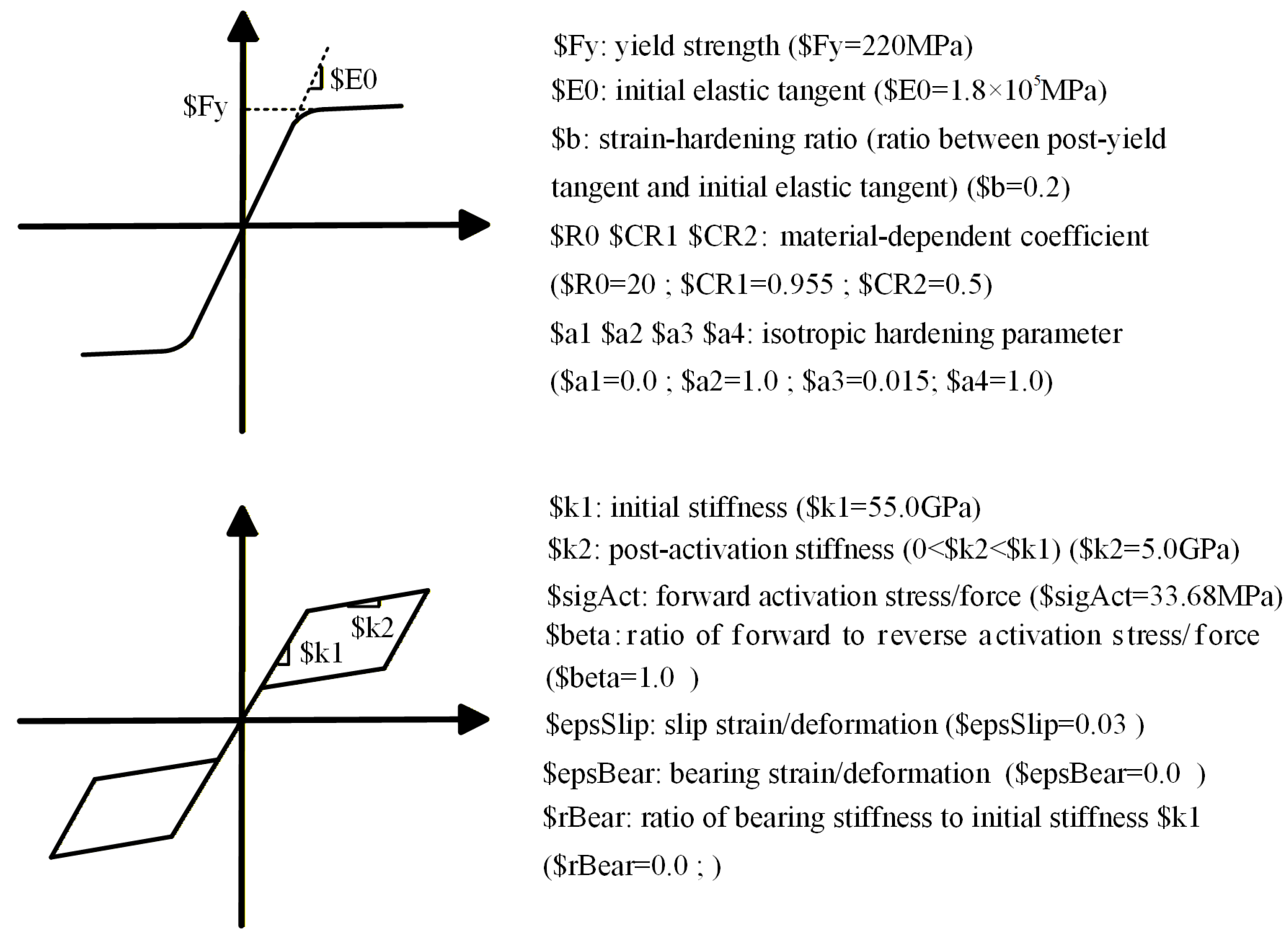
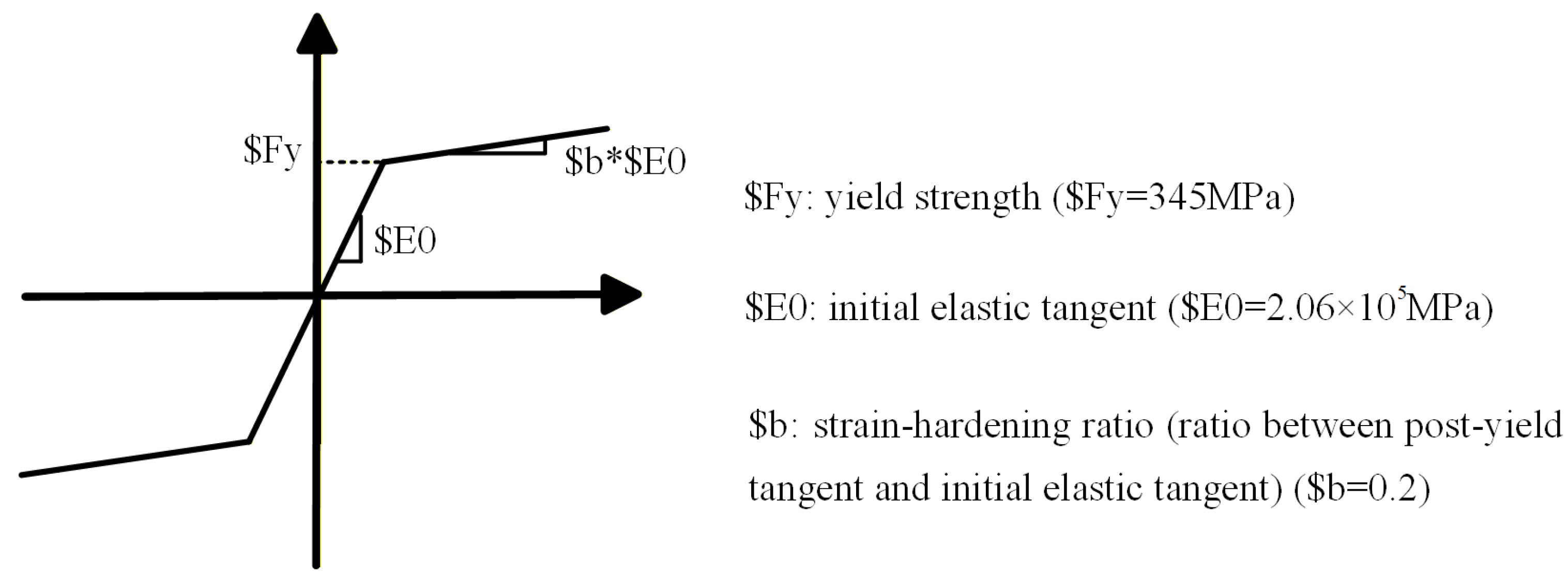
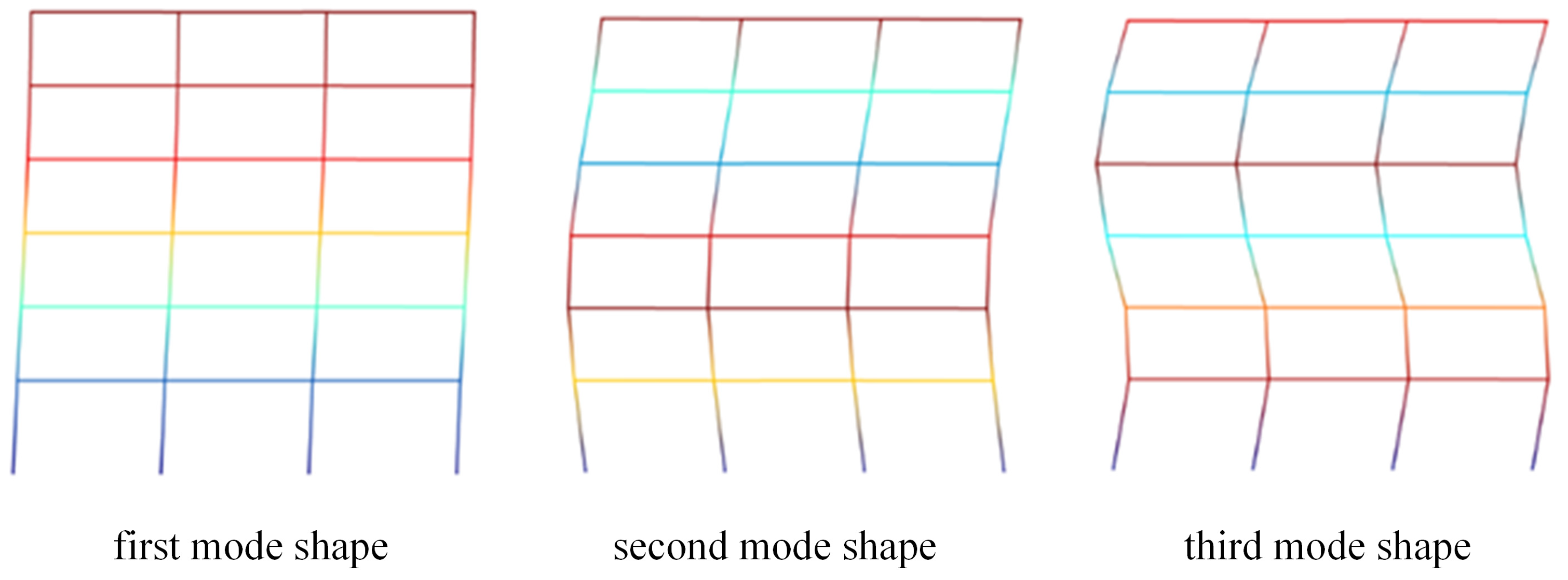
A six-story steel frame model is developed for numerical analysis. Beam and column members are modeled using the nonlinearBeamColumn element in OpenSees with fiber sections; this element is a force-based beam–column formulation that captures the spread of plasticity along the member through numerical integration. The steel material is simulated using the Steel01 uniaxial material model in the OpenSees material library; Steel01 is a uniaxial bilinear steel constitutive model with kinematic hardening (with optional isotropic hardening). The corresponding constitutive curve is provided in Figure 5, together with the Steel01 material parameters and their numerical values. The base of the frame is assumed to be fixed to the ground, and the story masses are assigned to the nodes according to the specified tributary distribution. Table 2 compares the first three modal periods of the developed model with those reported in the reference study. The maximum difference in the first three periods is within 5%, indicating good agreement and satisfying the accuracy requirement for the subsequent analyses. Figure 6 presents the corresponding mode shapes associated with the first three modal periods [44].
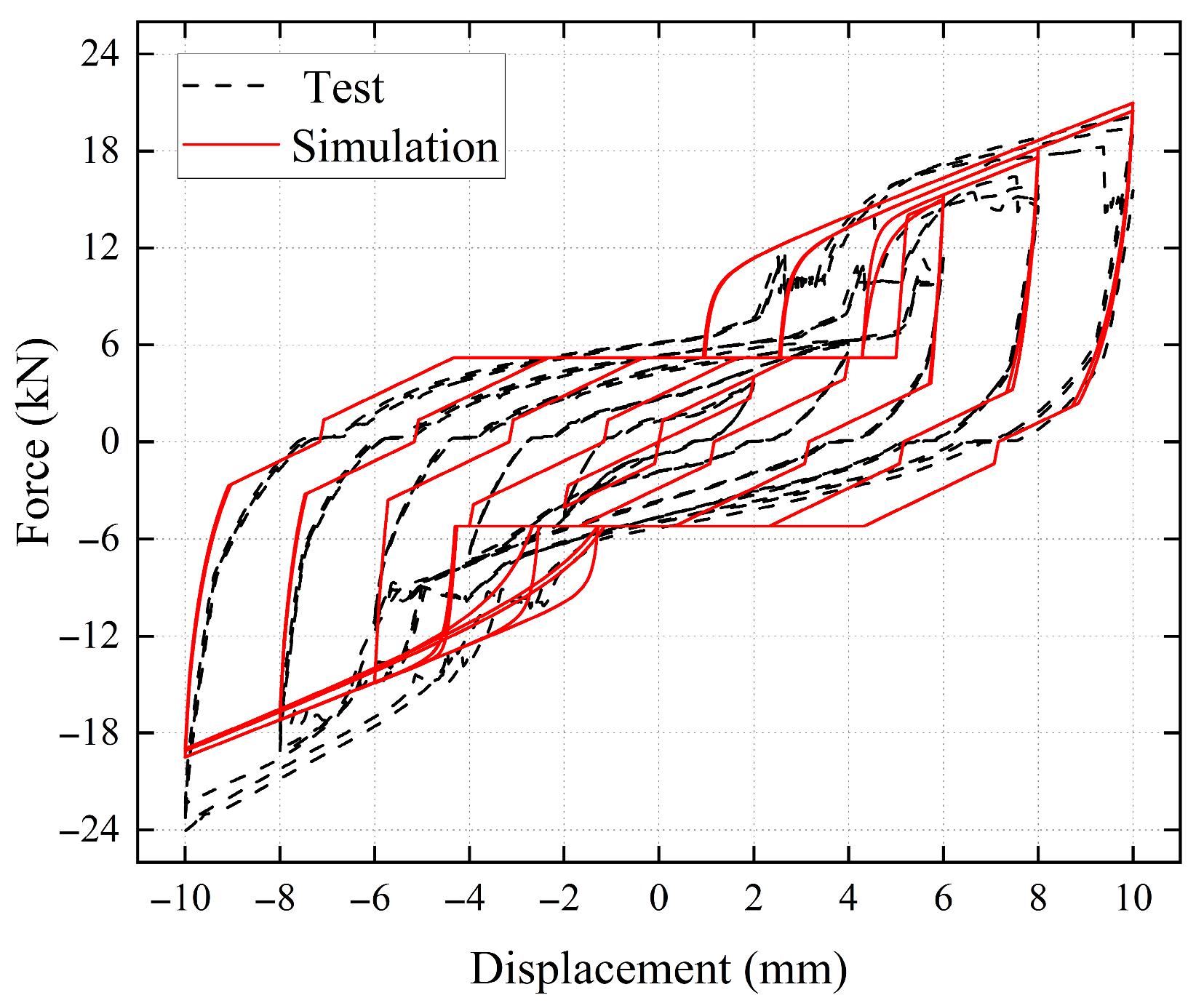
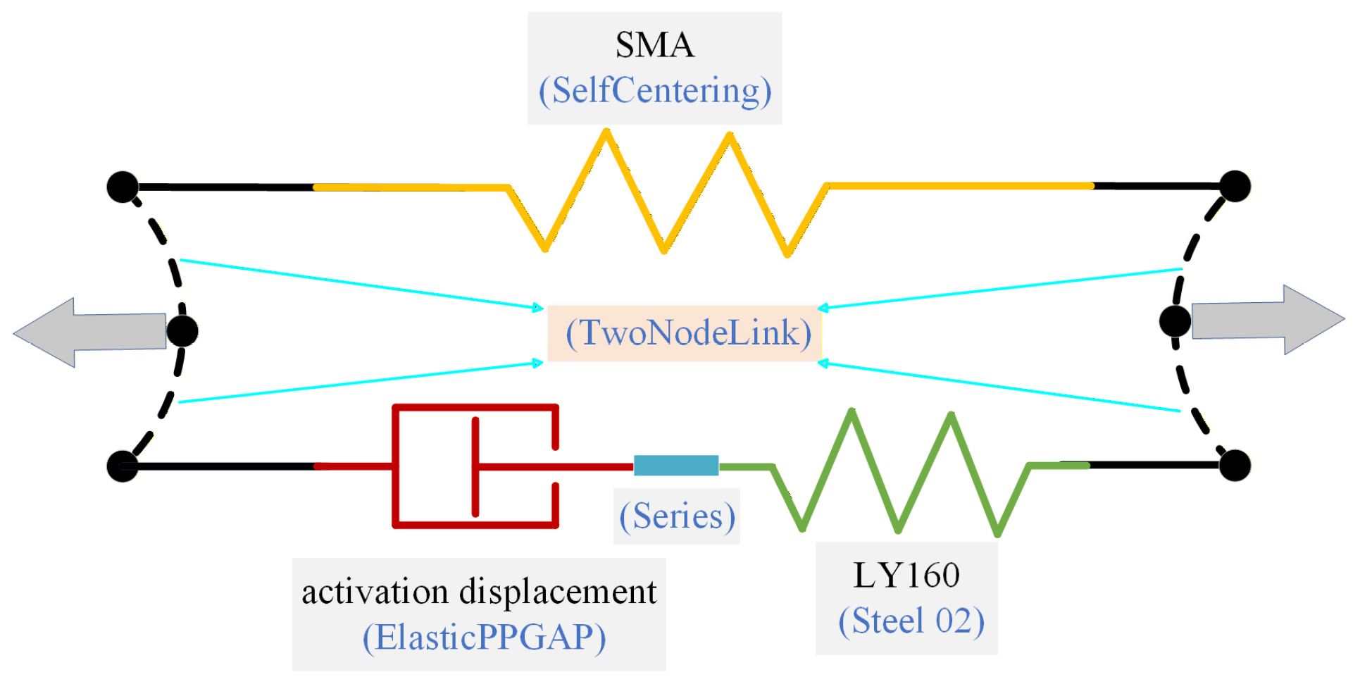
At the reserved brace locations, three types of braces are considered. The self-centering brace is modeled using the SelfCentering material, and the buckling-restrained brace is modeled using the Steel02 material; the corresponding constitutive curves and parameter values for SelfCentering and Steel02 are provided in Figure 7. The proposed SCDYB is modeled by placing these two components in parallel. The remaining materials (i.e., Parallel, ElasticPPGap, and Series) are used only as connector/assembly tools in OpenSees to (i) construct the activation displacement (gap) by combining two ElasticPPGap materials with opposite loading directions and (ii) connect the gap model in series with Steel02 to represent the second-stage core plate with an activation displacement. The detailed modeling scheme is shown in Figure 8. The comparison between the test results and numerical simulations is presented in Figure 9, demonstrating good agreement and adequate accuracy for subsequent analyses.

3.2. Selection of Ground Motions

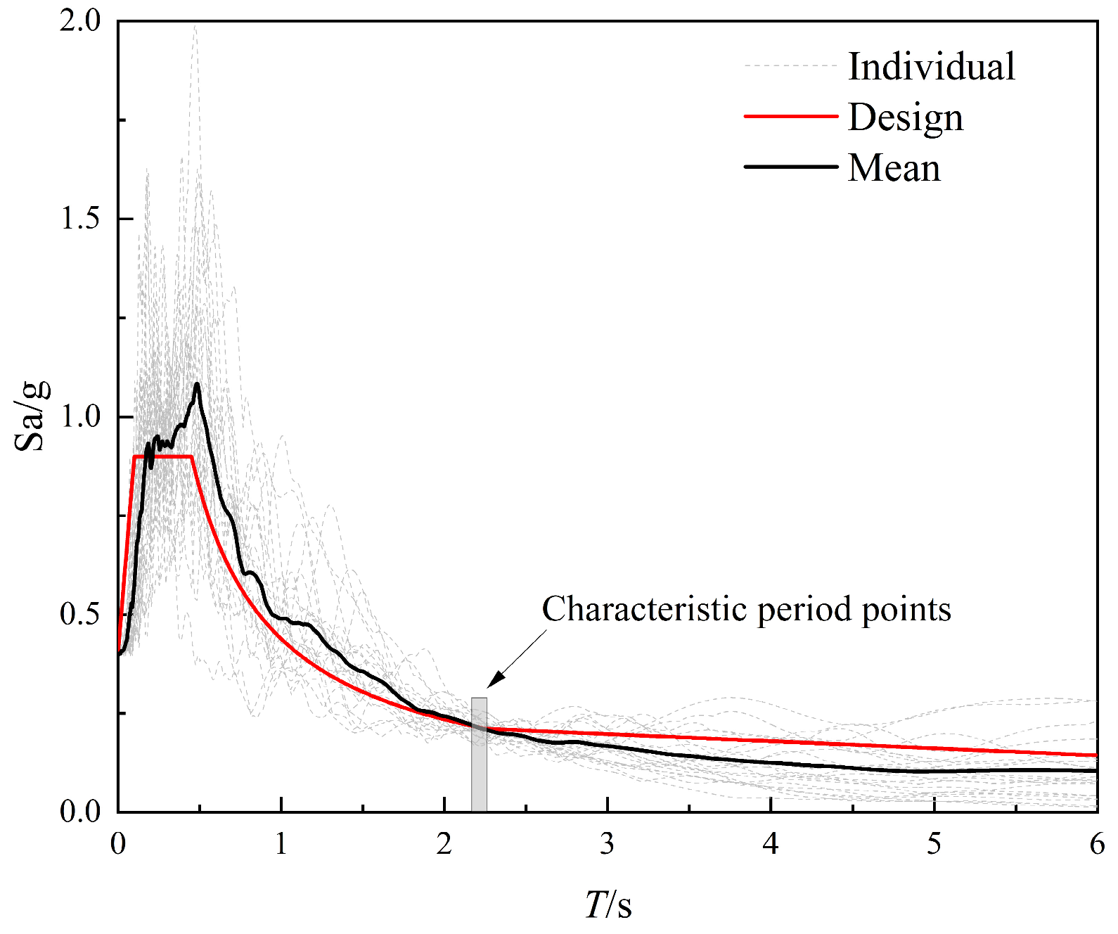
Based on the site conditions, seismic fortification intensity, and other seismic environmental parameters of the steel frame, a dual-band ground-motion selection method is adopted. This method yields a level of design reliability comparable to that of the code-based design response spectrum [45,46]. A total of 22 ground-motion records are selected from the earthquake ground-motion database of the Pacific Earthquake Engineering Research Center and used as seismic inputs. The response spectra of the selected records are shown in Figure 10, and the detailed information is summarized in Table 3.

4. Seismic Performance Evaluation

A six-story braced steel frame is analyzed, and three comparative cases are considered. Specifically, concentrically braced steel frames incorporating SCB, BRB, and SCDYB are established separately to evaluate the differences in seismic performance among the bracing systems. As shown in Figure 4, the braces are arranged in the middle bay using the same chevron (inverted-V) configuration for all three cases. Moreover, the brace layout and brace locations are identical in the three models; to represent different bracing systems, all braces at the reserved brace locations in the six-story frame are replaced with SCB, BRB, and SCDYB, respectively. This ensures a fair comparison of the control effectiveness of the three brace types under the same bracing configuration and placement (Figure 4).

4.1. Brace Layout

According to the recommendations in Ref. [42], the ratio of the fundamental period of the bare (uncontrolled) frame to that of the braced frame is preferably in the range of 1.5–2.0. When the brace area ratio is 0.5–1.0, the overall structural damage and the degree of non-uniform damage distribution are relatively small. Within this range, a brace area ratio of 0.5 is adopted as the initial value, and a parametric trial is then performed with an increment of 0.05. The brace area ratio for each story is finally determined as 0.9.
On this basis, an “equal-stiffness” principle is employed to design the SCB, BRB, and SCDYB systems, where the equivalent initial lateral stiffness of the steel frame with braces added is the same, ensuring that the three concentrically braced steel frames have the same fundamental period of 1.35 s. Compared to the fundamental period of the bare frame, the period ratio is approximately 1.6, which falls within the recommended range in Ref. [42]. This provides a rational basis for comparing different bracing schemes.

4.2. Peak Interstory Drift Ratios

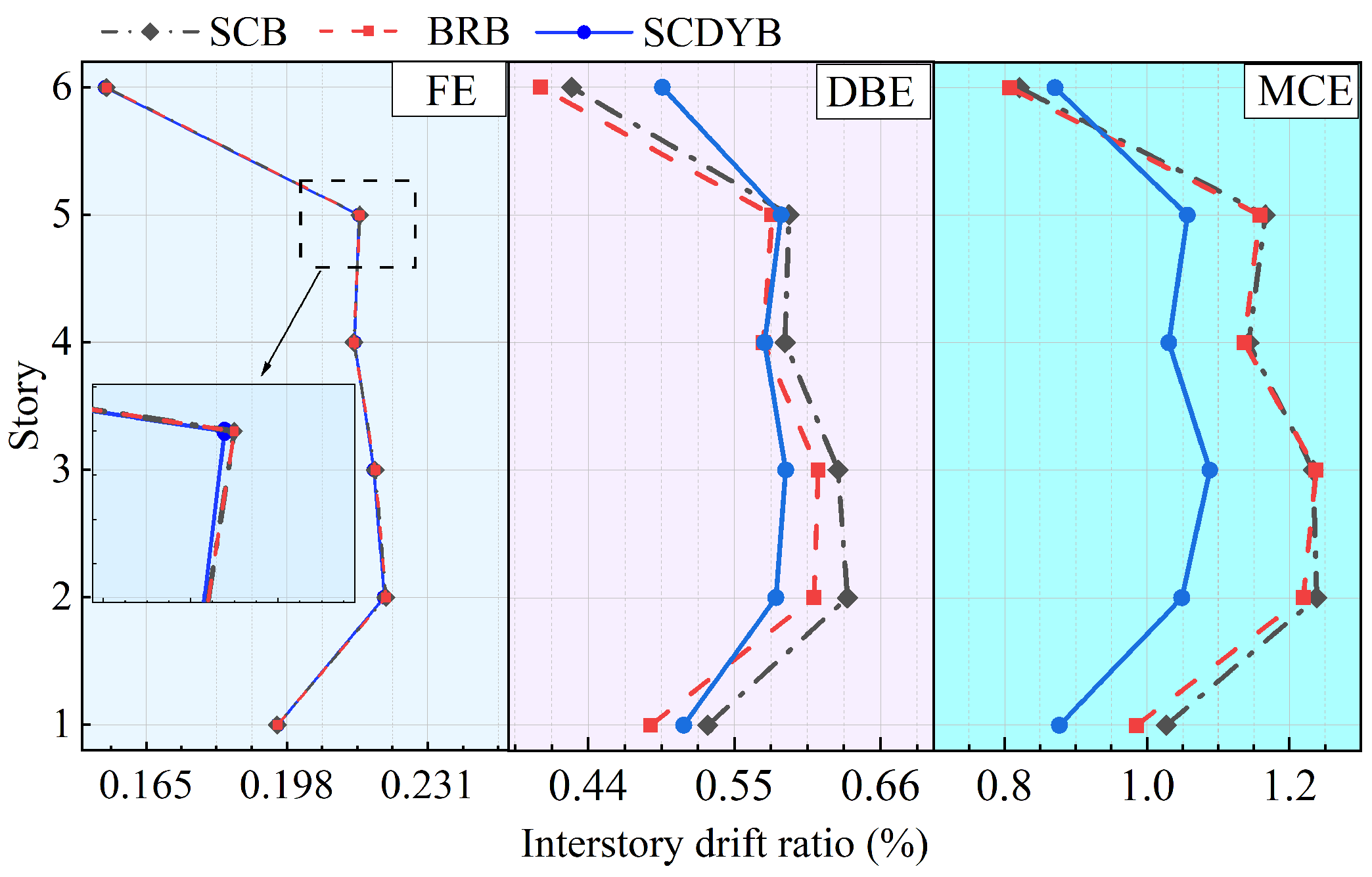
To evaluate the seismic response mitigation performance of different bracing systems, this study installs an SCB with a flag-shaped constitutive model to provide recentering capability, a BRB with a bilinear constitutive model to provide energy dissipation, and the proposed SCDYB that integrates the above two mechanisms and exhibits dual-stage yielding behavior, respectively, at the reserved brace locations of the six-story steel frame (Figure 4). The three brace devices correspond to different mechanical models, and their hysteretic models are shown in Figure 3. To evaluate the seismic response mitigation performance of different bracing systems under various hazard levels, the selected 22 ground-motion records are applied to the structural models in the X direction. The peak ground acceleration of each record is scaled to 0.07 g, 0.20 g, and 0.40 g, corresponding to frequent earthquake (FE), design-basis earthquake (DBE), and maximum considered earthquake (MCE), respectively, and nonlinear time-history analyses are performed [43]. Figure 11 presents the mean values of the peak interstory drift ratios for the three cases under each seismic hazard level, from which the following observations can be drawn.
(1) Under the frequent earthquake level, the peak interstory drift ratios of the three braced frames range approximately from 0.16% to 0.23%. The heightwise distribution is characterized by smaller drifts at the bottom and top stories (stories 1 and 6) and slightly larger drifts at the middle stories (stories 2–5), with only marginal differences among the three bracing systems. This behavior is mainly attributed to the equal-stiffness design adopted for all cases. At the FE level, the brace cores remain essentially elastic without significant yielding, resulting in limited energy dissipation. Consequently, the three bracing systems exhibit comparable interstory drift control.
(2) Under the design-basis earthquake level, the heightwise distribution pattern of interstory drift ratios is generally similar to that observed under the FE level; however, the differences among the three bracing systems become more pronounced. The SCDYB results in smaller interstory drifts overall and a more uniform distribution along the height, with particularly notable improvements at Stories 2–4. Because BRB can yield at relatively small deformation demands and thus dissipate input energy effectively, the frame equipped with BRB also exhibits good deformation control, except at Stories 2 and 3, where its performance is slightly inferior to that of the SCDYB, the frame equipped with BRB which performs well at the remaining stories. In contrast, owing to the relatively limited energy-dissipation capacity of SCB, the frame equipped with SCB exhibits larger interstory drifts than the other two systems.
(3) Under the maximum considered earthquake level, the second-stage core of the SCDYB yields and dissipates energy, resulting in significantly improved interstory drift control compared with the frame equipped with SCB and the frame equipped with BRB. Compared with the FE and DBE levels, the advantage of the SCDYB becomes more pronounced at the MCE level, indicating that, under large deformation demands, the energy-dissipation capacity of the second-stage core can be fully mobilized, thereby providing more effective seismic response mitigation. Overall, the SCDYB exhibits superior response control performance relative to both SCB and BRB.
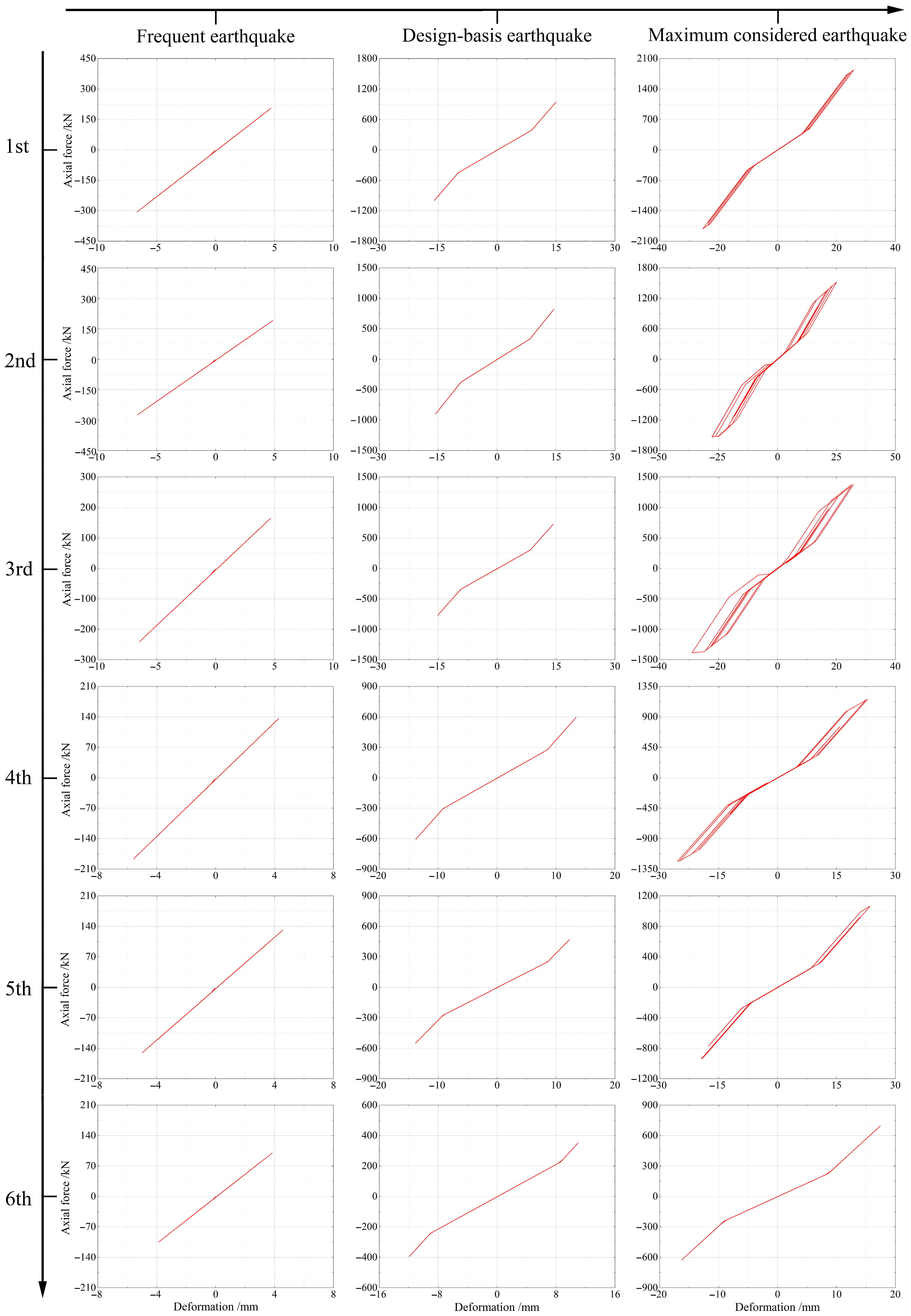
To further elucidate the response mitigation mechanism of the SCDYB, one ground-motion record (GM.09), whose response is closest to the mean of the 22 records, is selected as a representative input. Since the braces on each floor are symmetrically arranged in an inverted V configuration, the hysteresis curves for the same floor are quite similar. Therefore, the hysteresis curve for the brace on the left side of Figure 4 is selected as the representative for the corresponding floor. The story hysteresis curves under different seismic hazard levels are extracted and shown in Figure 12. The graph consists of three columns, corresponding to different seismic hazard levels: frequent earthquake, design-basis earthquake, and maximum considered earthquake. The rows correspond to the six floors of the structure, from the first to the sixth floor, from top to bottom. This allows for a comparison of axial force versus deformation for each story under various seismic conditions. The results indicate that under the frequent earthquake level, the restoring force is mainly provided by the first-stage core, while the second-stage core remains inactive. Under the design-basis earthquake level, the second-stage core begins to engage but remains in the elastic range, contributing limited energy dissipation. Under the maximum considered earthquake level, the first-stage and second-stage core plates work in coordination at each story. Notably, in the second and third stories, where interstory deformation is larger, the overall energy dissipation of the device is more significant.
It should be noted that, for the current parameter configuration (a relatively small activation displacement, with an activation-displacement ratio of 0.25), the brace parameters are determined following the conventional design approach for single-stage BRB. Consequently, the activation and yielding of the second-stage core may vary among stories, and the hysteresis curves of some stories do not exhibit an ideal fully superposed shape. In addition, owing to the difference between tension and compression behavior, the hysteretic responses exhibit a certain degree of asymmetry. Overall, the SCDYB can provide effective self-centering under FE excitation while achieving coupled recentering and energy dissipation under DBE and MCE excitations through the coordinated action of the first-stage and second-stage cores, thereby translating the staged device mechanism into improved global drift control, especially when the second-stage core is fully mobilized at higher hazard levels.

4.3. Interstory Drift Concentration

In building structural systems, the presence of a weak story has a significant influence on the global seismic performance. Due to insufficient strength and stiffness of structural components, a weak story can disrupt the original internal-force distribution under earthquake excitation, leading to pronounced concentration of forces and stresses. Its low lateral stiffness results in interstory drift demands that are substantially larger than those of adjacent stories, which may induce torsional response or global instability. Under seismic excitation, the weak story tends to concentrate seismic energy and is usually the first to enter the inelastic deformation stage, resulting in a marked degradation of load-carrying capacity and energy-dissipation capability. Consequently, the formation of a weak story is recognized as one of the primary causes of severe structural damage and even collapse.
The drift concentration factor (DCF) is a key quantitative index used to characterize the structural deformation pattern and the degree of interstory drift concentration, and it is defined as follows:
DCF = θ max θ roof
where θ max denotes the peak interstory drift ratio, and θ roof denotes the roof drift ratio. The minimum value of DCF is 1.00, indicating a perfectly uniform distribution of interstory drift ratios along the height. A larger DCF implies a more pronounced concentration of interstory deformation.
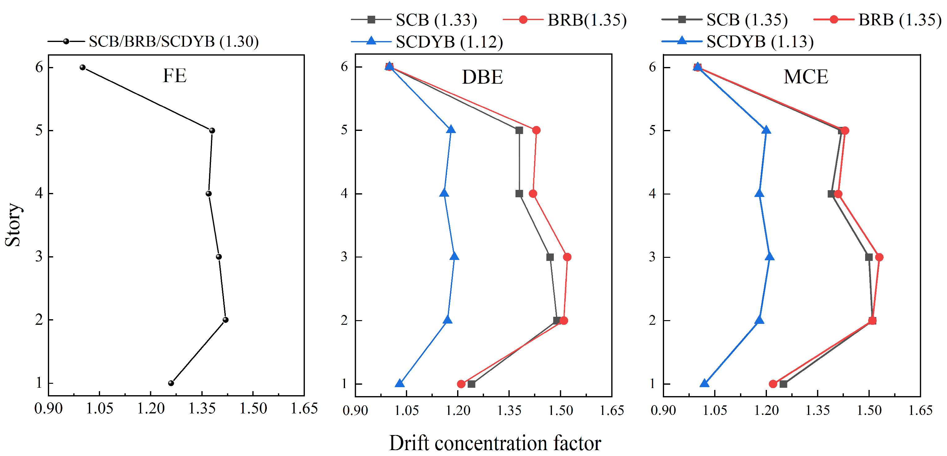
Figure 13 presents the drift concentration factors of the three braced frames under different seismic hazard levels; the value reported after each legend denotes the mean DCF of the corresponding braced-frame system. Under the frequent earthquake level, the DCF values are comparable among the three systems, which can be attributed to the equal-stiffness design and the essentially elastic behavior of all braces. Under the design-basis earthquake and maximum considered earthquake levels, the frame equipped with SCDYB exhibits smaller DCF values at all stories than the frame equipped with SCB and the frame equipped with BRB. Moreover, with increasing seismic intensity, the DCF of the SCDYB varies only slightly, indicating a stable and robust response mitigation performance. However, the results also indicate that, although BRB provides more effective reduction in interstory drift magnitude than SCB, its interstory drift distribution is less uniform.
Based on the above observations, the parameter design of the SCDYB should account for the dynamic characteristics of the structure and the story-dependent response demands. The activation-displacement ratio should be appropriately selected and adjusted for different stories. Timely activation of the second-stage core is essential at the target hazard level. It enables the core to participate effectively in force resistance and energy dissipation. This improves the energy-dissipation capacity and promotes more favorable internal-force redistribution. As a result, the overall seismic performance and deformation control of the structure are enhanced. In summary, an appropriate selection of the activation-displacement ratio ensures that the intended staged-working mechanism of the device can be effectively translated into improved global drift control and overall seismic performance at the structural level while contributing to a more uniform deformation pattern with a stable DCF under increasing seismic intensity.

4.4. Residual Displacement

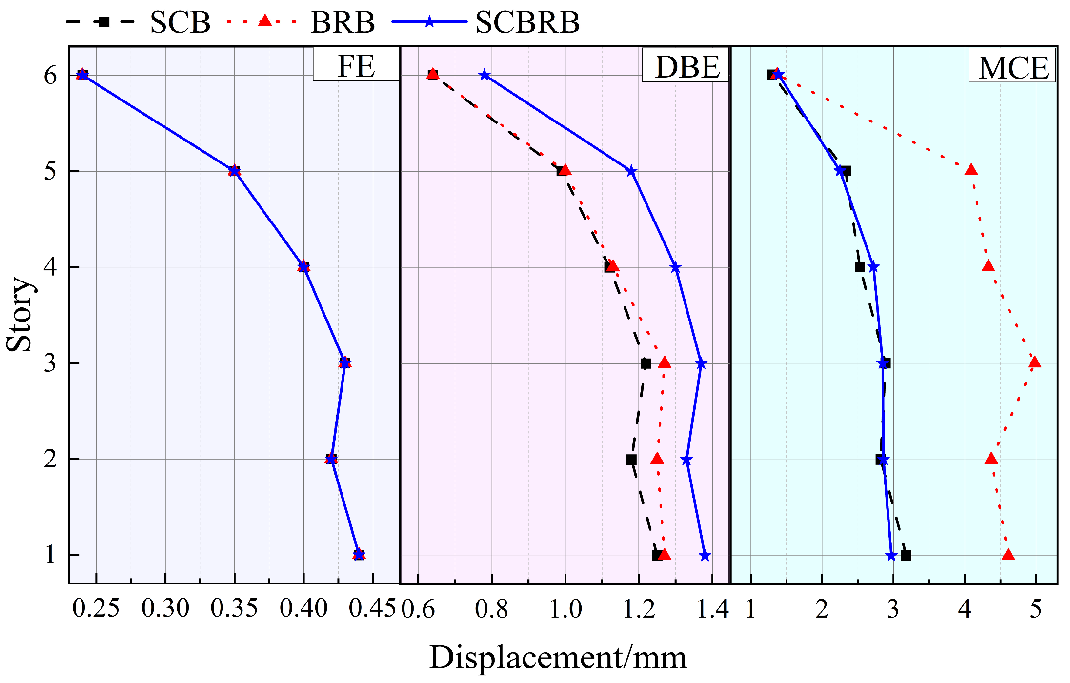
Figure 14 shows the mean residual story drifts at each floor under different seismic hazard levels. Under FE, the residual-drifts are comparable among the three systems because all braces remain essentially elastic; otherwise, due to different energy-dissipation characteristics, the residual drifts would differ noticeably at the structural level. Under DBE, the frame equipped with SCB and the frame equipped with BRB exhibit better residual drift control than the frame equipped with SCDYB. Specifically, SCB reduces residual deformation primarily through its recentering capability, while BRB yields and dissipates energy at DBE, which limits deformation and indirectly reduces residual drift.
In contrast, although the first-stage core of the SCDYB has begun to provide recentering, Figure 12 indicates that the second-stage core is still in the initial activation stage and has not yet contributed effective energy dissipation. For some relatively strong records, the second-stage core may undergo local yielding. The second-stage core may also enter a hardening regime before full development. This changes the internal force distribution within the device. This reduces the effectiveness of the first-stage core in limiting residual deformation. Meanwhile, although activation of the second-stage core is beneficial for reducing interstory drift, its contribution to the overall recentering mechanism is not yet fully mobilized at this hazard level.
Under the maximum considered earthquake level, the SCDYB and SCB cases exhibit comparable residual-drift control. This is primarily due to the second-stage core of the SCDYB fully entering the yielding energy-dissipation stage. This significantly enhances interstory drift control. This suppresses plastic deformation of the steel frame. Residual drifts remain at a relatively low level. By contrast, because BRB lacks an effective recentering mechanism, it exhibits relatively larger residual drifts after earthquakes, indicating weaker residual-deformation control.
Overall, the residual-drift results indicate that the effectiveness of the SCDYB in controlling post-earthquake deformation is strongly governed by the activation state of the second-stage core: limited activation at DBE can weaken residual-drift control, whereas full activation at MCE enables the staged mechanism to suppress frame plasticity and achieve residual-drift performance comparable to SCB, thereby demonstrating that the coordinated action of the two-stage cores is essential for realizing robust recentering effectiveness and stable residual-deformation control at higher hazard levels.

5. Parametric Analysis of the SCDYB

5.1. Parameter Description

For the parametric analysis, the SCDYB-related parameters are summarized in Table 4. The selected values of the yield-displacement ratio, stiffness ratio, and activation-displacement ratio are mainly determined by practical design considerations of the device: If the yield-displacement ratio or stiffness ratio is excessively large, the symmetric configuration of the SCDYB would require a substantial geometric discrepancy between the first-stage and second-stage core plates, leading to pronounced mechanical inconsistency and an increased risk of device instability. In addition, for the parameter matching between the SCDYB and the main steel frame, the yield-displacement ratio between the SCDYB and the steel frame is set to 0.3 and the stiffness ratio is set to 0.5, and the maximum considered earthquake (MCE) level is adopted as the input level to ensure timely activation of the device under strong ground-motion excitation so that it can engage early in force resistance and energy dissipation while keeping the peak interstory drift ratios of the six-story steel frame generally within the code limit of 2%. The different parameter combinations listed in Table 4 are used for the parametric study to evaluate the effects of the activation displacement and the yielding/stiffness matching between the two-stage core plates on the seismic response mitigation of the steel frame.
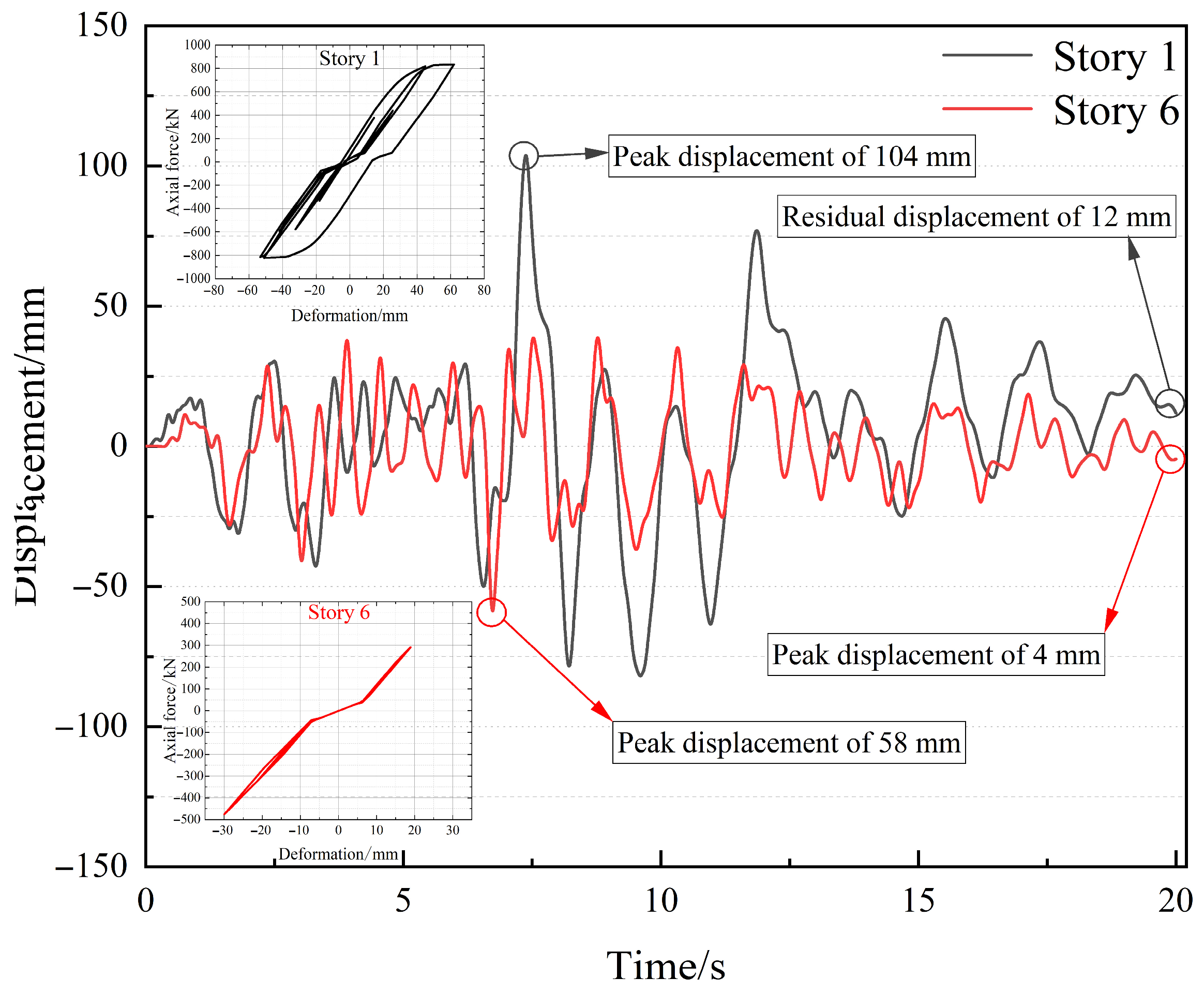
Figure 15 presents the time-history responses of the first and sixth stories of the steel frame. Figure 15 also shows the corresponding SCDYB hysteresis loops. The case has a yield-displacement ratio of 0.5 between the first-stage and second-stage cores, a stiffness ratio of 2.0, and an activation-displacement ratio of 1.25. The results indicate that the first story experiences relatively large seismic demands, with a peak displacement of 104 mm (corresponding to an interstory drift ratio of approximately 2.08%) and a residual displacement of 12 mm. The SCDYB hysteresis response at the first story exhibits stable and well-developed hysteretic behavior, and the second-stage core has fully yielded and dissipated energy. In contrast, the seismic response at the sixth story is considerably smaller, with a peak displacement of 58 mm (corresponding to an interstory drift ratio of approximately 1.1%) and a residual displacement of 4 mm. The corresponding hysteresis loop shows negligible energy dissipation, and the second-stage core remains in the elastic range.
It should be noted that the second-stage core may yield prior to the first-stage core when the activation-displacement ratio is 0.25 with a yield-displacement ratio smaller than 0.75, or when the activation-displacement ratio is 0.50 with a yield-displacement ratio smaller than 0.50. These cases are retained to maintain completeness of the dataset. However, because the second-stage core is fabricated from low-yield-point steel LY160, premature yielding may increase the risk of damage; such parameter combinations are therefore not recommended for practical design.

5.2. Yield Displacement Ratio

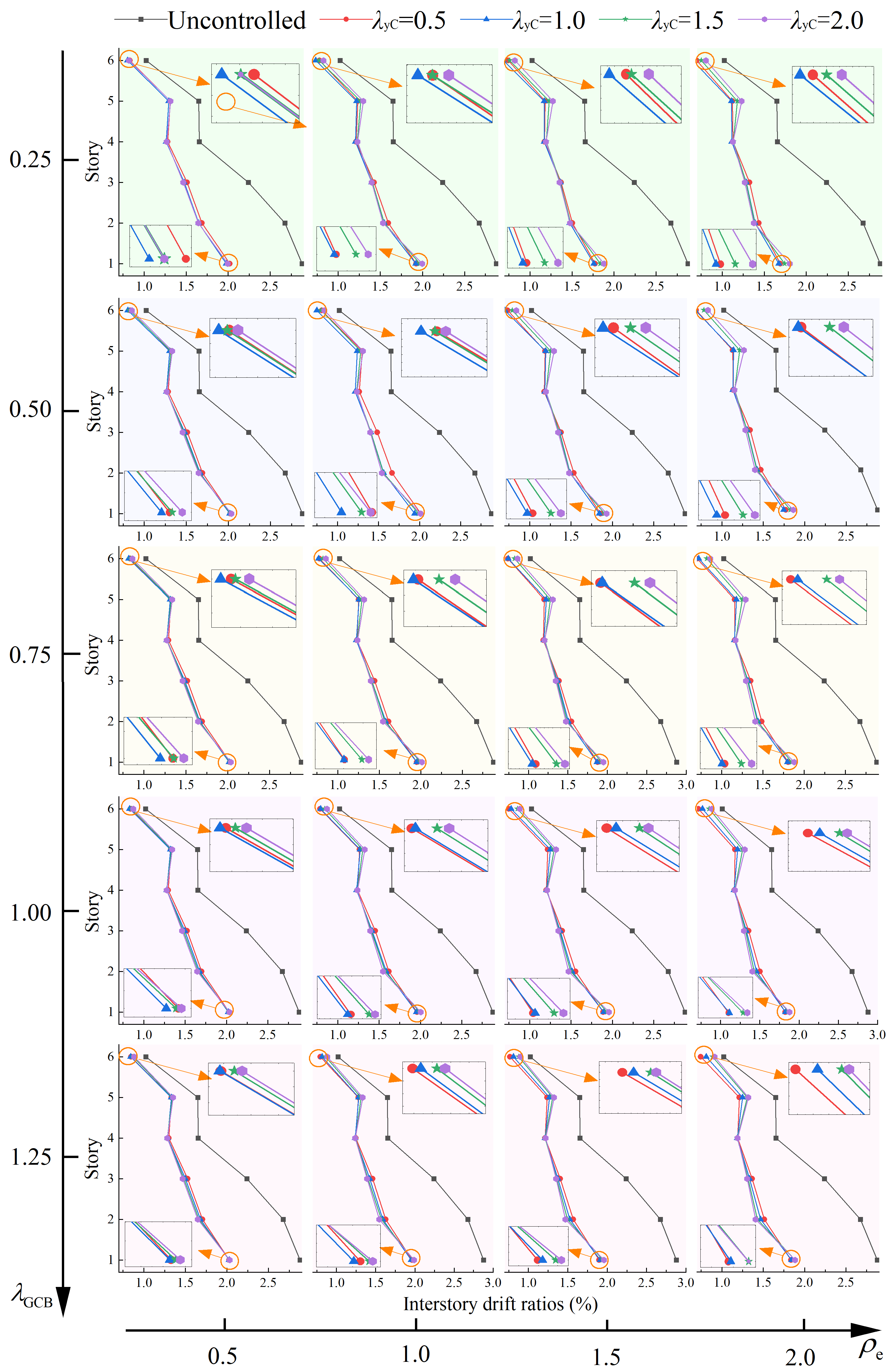
Figure 16 presents the mean values of the peak interstory drift ratios of the steel frame equipped with the SCDYB under different parameter combinations. The figure is arranged in a matrix form to facilitate direct comparison across the parameter space: moving from top to bottom, the activation-displacement ratio λGCB increases sequentially as 0.25, 0.50, 0.75, 1.00, and 1.25; moving from left to right, the stiffness ratio ρe increases sequentially as 0.50, 1.00, 1.50, and 2.00. For each (λGCB, ρe) combination, the mean peak interstory drift ratio profile along the building height is plotted, allowing the effects of the yield-displacement ratio on the interstory drift response to be compared under different combinations of activation-displacement ratio and stiffness ratio. Overall, the structural responses vary with the parameter combinations. Accordingly, the following three aspects are discussed.
  • Influence of the yield-displacement ratio on interstory drift
With an increase in the yield-displacement ratio, the interstory drift ratios generally decrease. For some parameter combinations, the structural response is relatively large and the working state of the device is similar, and thus the differences among various yield-displacement ratios are not pronounced when the overall drift demand is high. When the interstory drift ratios are relatively small, the differences among the yield-displacement-ratio cases become clearer. Taking Story 6 as an example, when the yield-displacement ratio increases from 1.0 to 1.5, a more distinct separation in interstory drift response is observed, indicating that the response is more sensitive to the yield-displacement ratio within this range. Overall, the yield-displacement ratio should not be too small, and a value no less than 1.0 is recommended.
2.
Influence of the activation-displacement ratio on the effect of the yield-displacement ratio
Taking the first story, which is more sensitive to the activation-displacement ratio, as an example, when the activation-displacement ratio is small (e.g., 0.25), the interstory drift responses corresponding to different yield-displacement ratios show more evident differences. As the activation-displacement ratio increases, the interstory drift responses for different yield-displacement ratios gradually converge, while the overall drift level increases. This indicates that a larger activation-displacement ratio delays the activation and energy-dissipation engagement of the second-stage core, thereby reducing the energy-dissipation contribution of the device and weakening deformation control. Therefore, provided that the design objectives are satisfied, the activation-displacement ratio should not be overly large; a value not exceeding 0.5 is recommended.
3.
Influence of the stiffness ratio on the effect of the yield-displacement ratio
As the stiffness ratio increases, the interstory drift ratios decrease overall, indicating that, for a given yield-displacement ratio, increasing the stiffness ratio is beneficial for improving deformation control. In particular, when the stiffness ratio is 2.0 (e.g., at story 6), the influence of the yield-displacement ratio on interstory drift becomes more pronounced, suggesting that a higher stiffness ratio amplifies the effectiveness of the yield-displacement ratio in response control. However, an excessively large stiffness ratio leads to greater size differences between the first-stage and second-stage core plates, which is unfavorable for practical configuration and force-transfer stability. Considering both seismic control effectiveness and constructability, the stiffness ratio should not be too large; a value not exceeding 2.0 is recommended.
In summary, the parametric results indicate that drift control is jointly governed by the yield-displacement ratio, activation-displacement ratio, and stiffness ratio through their influence on the staged engagement of the SCDYB. A yield-displacement ratio no less than 1.0 helps maintain stable drift reduction, whereas an overly large activation-displacement ratio delays the participation of the second-stage core and weakens deformation control (thus a value not exceeding 0.5 is preferred). Increasing the stiffness ratio generally improves drift control and can enhance the sensitivity to the yield-displacement ratio, but it should be limited for constructability and force-transfer stability (recommended not exceeding 2.0).

5.3. Stiffness Ratio

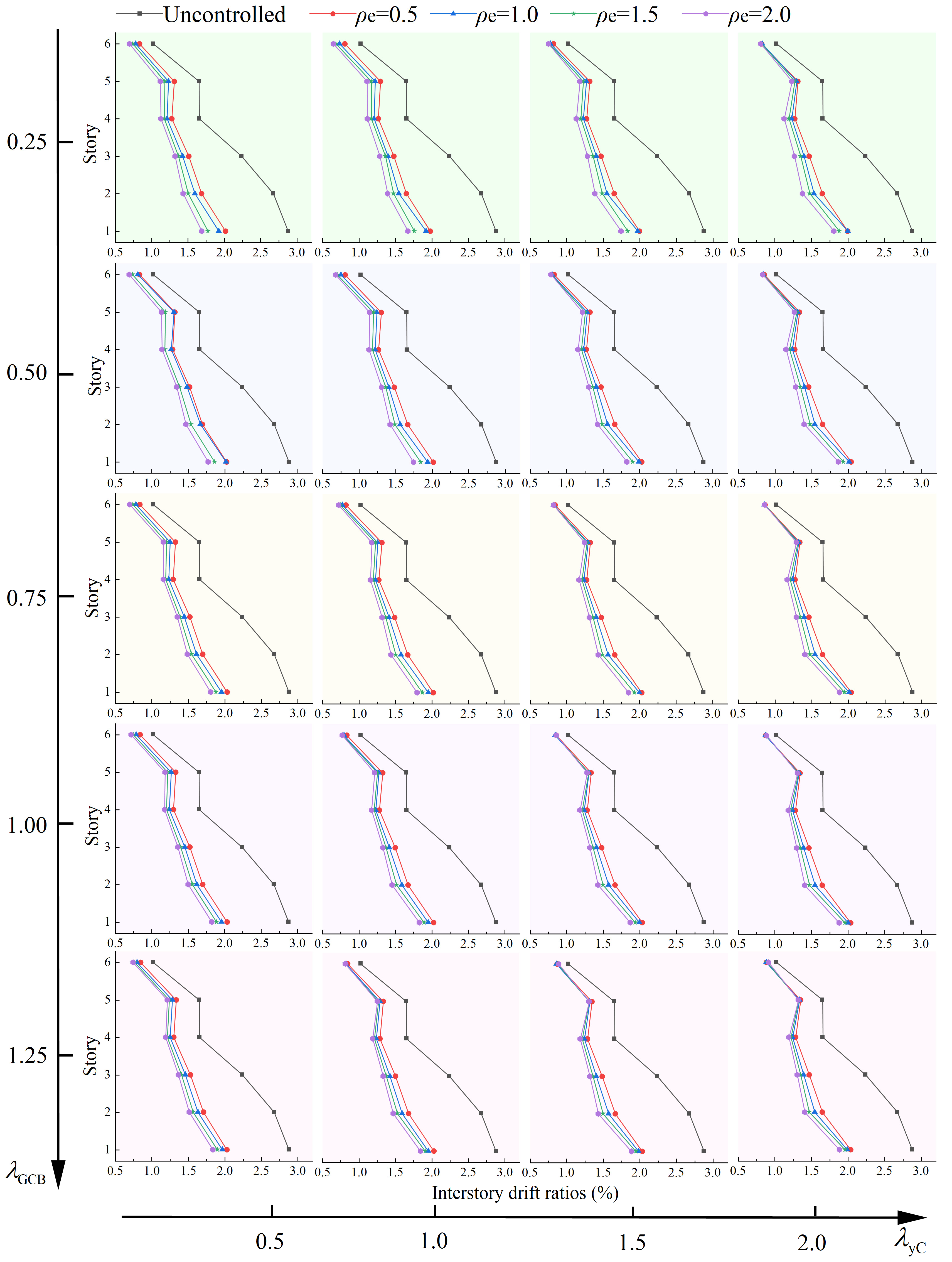
Figure 17 illustrates the variation in interstory drift control with stiffness ratio under different combinations of activation-displacement ratio and yield-displacement ratio, as can be observed:
(1)
Influence of the stiffness ratio on interstory drift
Compared with the yield-displacement ratio, the stiffness ratio exerts a more pronounced influence on interstory drift under various combinations of activation-displacement ratio and yield-displacement ratio. With increasing stiffness ratio, the interstory drift ratios at all stories (stories 1–6) exhibit a clear decreasing trend.
(2)
Influence of the activation-displacement ratio on the effect of the stiffness ratio
Taking the first story as an example, as the activation-displacement ratio increases, the differences in interstory drift among the stiffness-ratio cases gradually diminish, indicating that a larger activation-displacement ratio reduces the discriminability of stiffness ratio in controlling the first-story deformation. This trend is more evident than that observed for the yield-displacement ratio, further indicating that the stiffness ratio is generally more sensitive in affecting the response.
(3)
Influence of the yield-displacement ratio on the effect of the stiffness ratio
Taking the sixth story as an example, as the yield-displacement ratio increases, the change in interstory drift remains relatively limited. Meanwhile, the differences in interstory drift among the stiffness-ratio cases tend to decrease, indicating that a larger yield-displacement ratio at this story reduces the discriminability of stiffness ratio in the response.
Overall, after installing the SCDYB, the interstory drift ratios of the steel frame are substantially reduced at all stories. In addition, the stiffness ratio and activation-displacement ratio show higher sensitivity in drift control. Within a practical range, increasing the stiffness ratio and decreasing the activation-displacement ratio are beneficial for enhancing deformation control and amplifying the response differences among different parameter cases.

5.4. Activation-Displacement Ratio

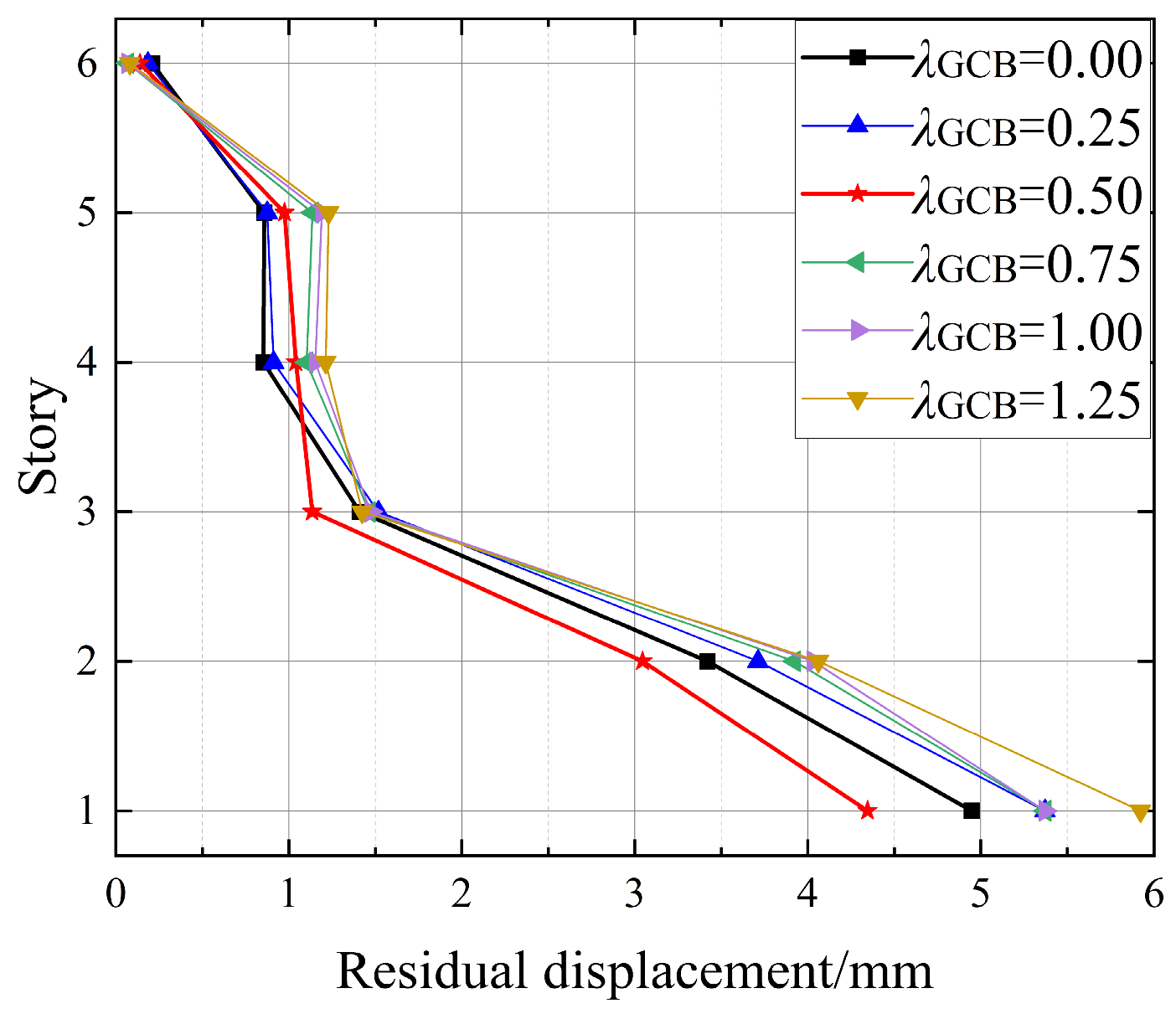
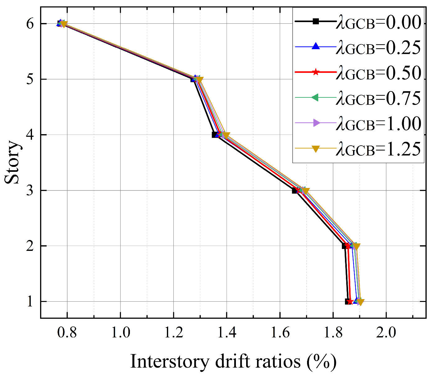
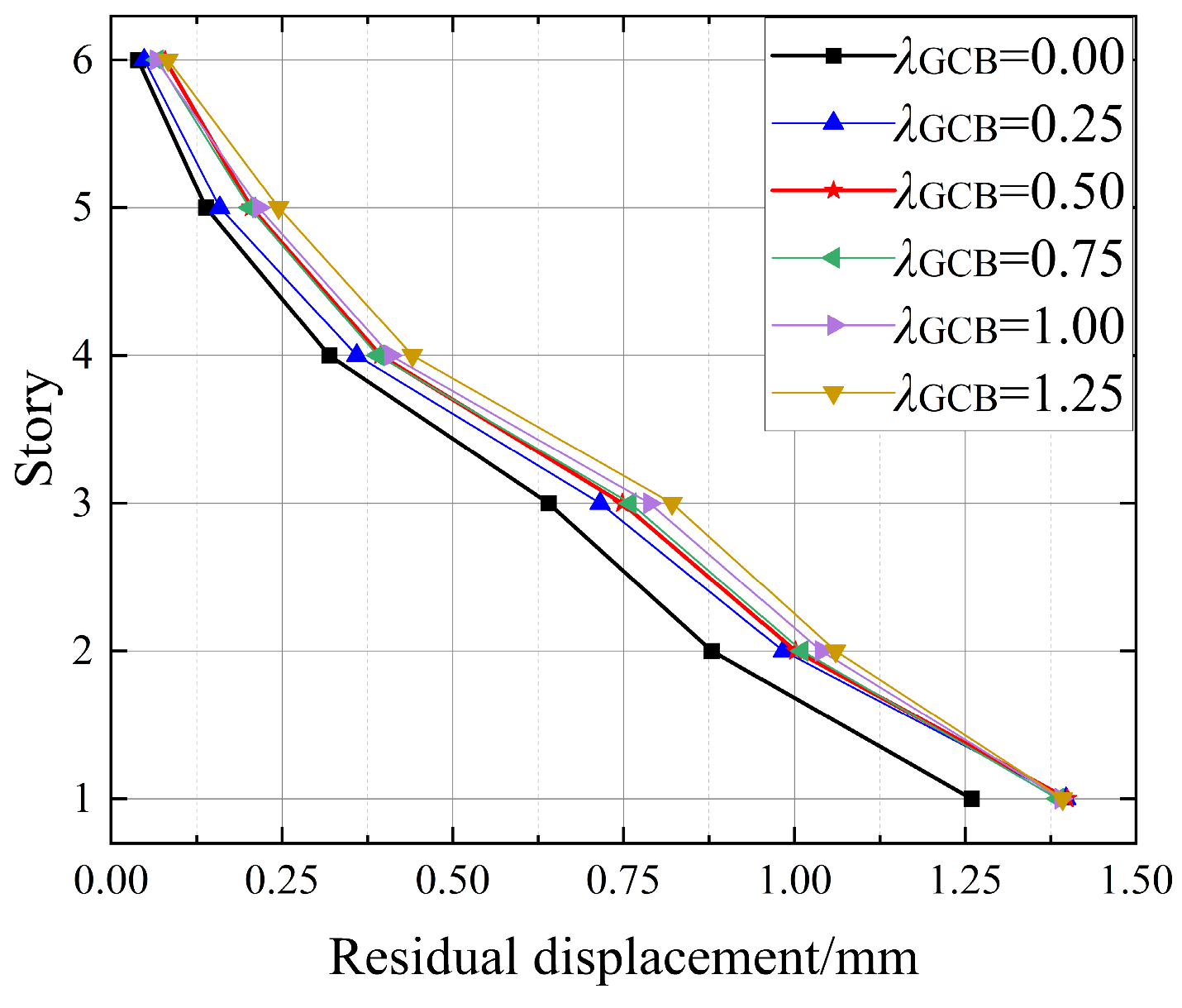
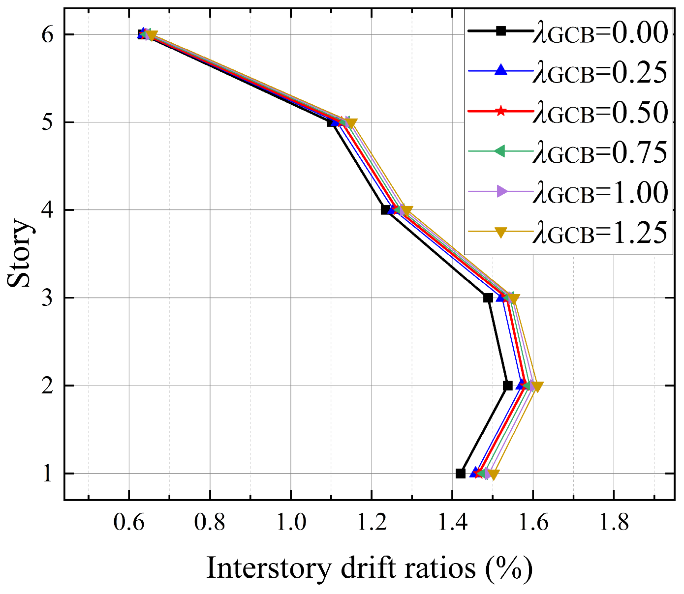
To clarify the influence of the activation-displacement ratio on the performance of the SCDYB, nonlinear time-history analyses are conducted for steel frames equipped with SCDYB having different activation-displacement ratios. The residual displacements and peak interstory drift ratios at each story are shown in Figure 18 and Figure 19, respectively. As indicated in Figure 18, for Stories 1–3 (where the interstory drift demands are relatively large, as shown in Figure 19), the smallest residual displacements are obtained when the activation-displacement ratio is 0.5. For Stories 4–6, the residual displacement levels are comparable when the activation-displacement ratio is 0 and 0.25.
Figure 19 shows that when the activation-displacement ratio is 0 (i.e., no gap is provided and the second-stage core engages from the beginning of loading), the peak interstory drift ratios are the smallest. However, when the activation-displacement ratio is 0.5, the interstory drift ratios are smaller than those for the case with an activation-displacement ratio of 0.25. This phenomenon may be attributed to the material behavior of the second-stage core and the cooperative recentering mechanism of the device. The second-stage core is made of conventional steel; after entering the yielding–hardening stage, it may accumulate relatively large residual deformation and provide additional resistance against the recentering of the first-stage core during unloading and recentering. Introducing an appropriate activation displacement provides a gap at the early loading stage, delaying the engagement of the second-stage core and reducing its reverse constraint during recentering. Consequently, the self-centering action of the first-stage core becomes more effective in controlling residual displacement. Compared with the case without a gap, introducing an activation displacement can reduce the resistance during recentering and improve residual deformation control.
To further examine the generality of this trend, the stiffness ratio between the SCDYB and the steel frame is increased to twice its original value. The corresponding residual displacements and interstory drift ratios are shown in Figure 20 and Figure 21, respectively. The results indicate that increasing the stiffness ratio leads to an overall reduction in both residual displacements and interstory drift ratios, confirming that a higher stiffness ratio is beneficial for improving displacement response control, which is consistent with common understanding. Meanwhile, because the overall deformation demand decreases, the modulation effect of the activation displacement on the engagement process of the second-stage core becomes less pronounced, and the response differences among cases with different activation-displacement ratios consequently diminish. Therefore, provided that the target performance is satisfied, a rational combination of the activation-displacement ratio, yield-displacement ratio, and stiffness ratio can achieve a more economical and effective seismic response mitigation performance.

6. Conclusions

A novel self-centering dual-stage yielding buckling-restrained brace (SCDYB) is proposed. The proposed device features a simple configuration and a stable, reliable load-transfer mechanism while providing both recentering capability and energy-dissipation capacity. A mechanical model and a dimensionless parameterization scheme are developed for the proposed brace. The brace is then implemented in a six-story single-bay steel frame, and nonlinear time-history analyses are conducted to compare the seismic performance of steel frames equipped with the proposed brace, a self-centering brace (SCB), and a buckling-restrained brace (BRB). The comparisons include peak interstory deformation, weak-story characteristics, and residual displacement responses. Finally, a parametric study is performed for the steel frame equipped with the proposed brace to quantify the influence of key parameters and to provide design-oriented references for practical applications. The main conclusions are summarized as follows:
  • The SCDYB integrates and further improves the configurations and force-resisting characteristics of BRB and SCB. In terms of load transfer, it inherits the simplicity and reliability of multi-stage yielding BRB that resists axial forces through direct tension–compression of core plates. In terms of recentering, an SMA plate is adopted as the first-stage recentering core component, which avoids the complex force-transfer mechanisms commonly required in conventional self-centering braces. In terms of energy dissipation, the second-stage core plates are fabricated from low-yield-point steel LY160, and their engagement in force resistance and energy dissipation is regulated through a prescribed activation displacement, enabling cooperative interaction with the recentering action of the first-stage core and thus improved residual deformation control.
  • The frame equipped with SCDYB exhibits overall superior performance in controlling lateral displacement responses and residual deformations compared with the frame equipped with SCB and the frame equipped with BRB. Due to the activation-displacement mechanism, the participation of the second-stage core is limited under FE, and the advantages of the SCDYB are mainly reflected in a more uniform distribution of interstory drifts. Under DBE and MCE, the second-stage core is progressively activated and enters the energy-dissipation stage, and the response mitigation advantage of the SCDYB becomes more pronounced.
  • Within the investigated parameter ranges, the yield-displacement ratio has a relatively small influence on displacement response control; however, to ensure timely engagement in force resistance and energy dissipation, the yield-displacement ratio should not be excessively large. The stiffness ratio has a more significant effect on displacement response control; increasing the stiffness ratio reduces interstory drift, whereas an overly large stiffness ratio is unfavorable for practical configuration and increases cost. Considering both seismic control effectiveness and constructability, the recommended parameter ranges are: the yield-displacement ratio should be no less than 1.0, the stiffness ratio should be no greater than 2.0, and the activation-displacement ratio should be no greater than 0.5.
  • Increasing the activation-displacement ratio delays the engagement of the second-stage core in energy dissipation and is generally unfavorable for displacement response control. However, with a rational parameter combination, the gap travel introduced by the activation displacement can reduce the reverse constraint imposed by the second-stage core during recentering, working together with the recentering capability of the first-stage core to improve residual displacement control. Within a certain range, appropriate activation-displacement ratios can result in better overall control performance than the case without an activation displacement.

Author Contributions

Conceptualization, Y.S.; methodology, Y.S.; software, Q.C.; validation, Q.C.; formal analysis, Q.C.; investigation, H.Q.; resources, H.Q.; data curation, Q.C.; writing—original draft preparation, Q.C.; writing—review and editing, Y.S.; visualization, Y.D.; supervision, Y.S.; project administration, H.Q.; funding acquisition, H.Q. All authors have read and agreed to the published version of the manuscript.

Funding

The research described in this paper was financially supported by the National Natural Science Foundation of China Grant (No. 52468071).

Data Availability Statement

The original contributions presented in this study are included in the article. Further inquiries can be directed to the corresponding author.

Conflicts of Interest

The authors declare no conflicts of interest.

Abbreviations

The following abbreviations are used in this manuscript:
BRBbuckling-restrained brace
SCBself-centering brace
SMAshape memory alloy
SCDYBself-centering dual-stage yielding buckling-restrained brace
FEfrequent earthquake
DBEdesign-basis earthquake
MCEmaximum considered earthquake
DCFdrift concentration factor

References

  1. Clifton, C.; Bruneau, M.; MacRae, G.; Leon, R.; Fussell, A. Steel building damage from the Christchurch earthquake series of 2010/2011. SESOC J. 2011, 24, 27–42. [Google Scholar]
  2. MacRae, G.A.; Clifton, G.C. Research on seismic performance of steel structures. In Proceedings of the Steel Innovations 2015 Conference, Auckland, New Zealand, 3–4 September 2015; pp. 3–4. [Google Scholar]
  3. Miller, D.K. Lessons learned from the Northridge earthquake. Eng. Struct. 1998, 20, 249–260. [Google Scholar] [CrossRef]
  4. Tremblay, R.; Filiatrault, A.; Bruneau, M.; Nakashima, M.; Prion, H.G.; DeVall, R. Seismic design of steel buildings: Lessons from the 1995 Hyogo-ken Nanbu earthquake. Can. J. Civ. Eng. 1996, 23, 727–756. [Google Scholar] [CrossRef]
  5. Ye, L.; Lu, X.; Qu, Z.; Peng, F. Analysis on building seismic damage in the Wenchuan earthquake. In Proceedings of the 14th World Conference on Earthquake Engineering (14WCEE), Beijing, China, 12–17 October 2008. [Google Scholar]
  6. Bruneau, M.; MacRae, G. Reconstructing Christchurch: A Seismic Shift in Building Structural Systems; The Quake Centre, University of Canterbury: Christchurch, New Zealand, 2017. [Google Scholar]
  7. Clifton, C.; Bruneau, M.; MacRae, G.; Leon, R.; Fussell, A. Steel structures damage from the Christchurch earthquake series of 2010 and 2011. Bull. New Zealand Soc. Earthq. Eng. 2011, 44, 297–318. [Google Scholar] [CrossRef]
  8. Tremblay, R.; Filiatrault, A.; Timler, P.; Bruneau, M. Performance of steel structures during the 1994 Northridge earthquake. Can. J. Civ. Eng. 1995, 22, 338–360. [Google Scholar] [CrossRef]
  9. Bradley, C.R.; Fahnestock, L.A.; Hines, E.M.; Sizemore, J.G. Full-scale cyclic testing of low-ductility concentrically braced frames. J. Struct. Eng. 2017, 143, 04017029. [Google Scholar] [CrossRef]
  10. Shi, Y.; Wang, J.; Qin, H.; Han, J.; Liu, Y. Constant-strength residual displacement ratio spectra for SDOF systems with energy-dissipating fuses. Soil Dyn. Earthq. Eng. 2025, 190, 109163. [Google Scholar] [CrossRef]
  11. Della Corte, G.; D’Aniello, M.; Landolfo, R.; Mazzolani, F.M. Review of steel buckling-restrained braces. Steel Constr. 2011, 4, 85–93. [Google Scholar] [CrossRef]
  12. AlHamaydeh, M.; Abed, F.; Mustapha, A. Key parameters influencing performance and failure modes for BRBs using nonlinear FEA. J. Constr. Steel Res. 2016, 116, 1–18. [Google Scholar] [CrossRef]
  13. Ding, Y.; Shi, Y.; Qin, H.; Pei, Y.; Chen, B. Ductility demand spectra for marine structures characterized by the self-centering system with the flag-shaped model under offshore ground motions. Adv. Struct. Eng. 2025, 29, 352–364. [Google Scholar] [CrossRef]
  14. Shi, Y.; Zhong, Z.; Qin, H.; Han, J.; Sun, Z. Toggle buckling-restrained brace systems and a corresponding design method for the seismic retrofit of bridge bents. Eng. Struct. 2020, 221, 110996. [Google Scholar] [CrossRef]
  15. Hu, S.; Wang, W.; Qu, B. Seismic economic losses in mid-rise steel buildings with conventional and emerging lateral force resisting systems. Eng. Struct. 2020, 204, 110021. [Google Scholar] [CrossRef]
  16. Dyanati Badabi, M. Seismic Performance Evaluation and Economic Feasibility of Self-Centering Concentrically Braced Frames. Ph.D. Thesis, University of Akron, Akron, OH, USA, 2016. [Google Scholar]
  17. Shi, Y.; Pei, Y.; Han, J.; Chen, B.; Wang, B. Strength reduction factor spectra of self-centering SDOF systems with flag-shaped model subjected to offshore ground motions. Soil. Dyn. Earthq. Eng. 2024, 184, 108801. [Google Scholar] [CrossRef]
  18. Pour, M.M.; Monajemi Nejad, S.; Sarvgad Moghadam, A. Experimental and numerical study of self-centering brace with arc steel plate. Buildings 2025, 15, 40. [Google Scholar] [CrossRef]
  19. Fang, C.; Wang, W.; Qiu, C.; Hu, S.; MacRae, G.A.; Eatherton, M.R. Seismic resilient steel structures: A review of research, practice, challenges and opportunities. J. Constr. Steel Res. 2022, 191, 107172. [Google Scholar] [CrossRef]
  20. Pan, P.; Cao, Y.; Wang, H.; Sun, J. Development of double-stage yielding coupling beam damper. J. Constr. Steel Res. 2020, 172, 106147. [Google Scholar] [CrossRef]
  21. Yang, C.; Xie, L.; Liu, Q.; Li, A.; Wang, X.; Liu, Q. Experimental and numerical investigations of a novel parallel double-stage crawler-track-shaped shear damper. Thin-Walled Struct. 2024, 195, 111428. [Google Scholar] [CrossRef]
  22. Hu, B.; Min, Y.; Wang, C.; Xu, Q.; Keleta, Y. Design, analysis and application of the double-stage yield buckling restrained brace. J. Build. Eng. 2022, 48, 103980. [Google Scholar] [CrossRef]
  23. Miller, D.J. Development and Experimental Validation of Self-Centering Buckling-Restrained Braces with Shape Memory Alloy. Ph.D. Thesis, University of Illinois at Urbana-Champaign, Urbana, IL, USA, 2011. [Google Scholar]
  24. Miller, D.J.; Fahnestock, L.A.; Eatherton, M.R. Development and experimental validation of a nickel–titanium shape memory alloy self-centering buckling-restrained brace. Eng. Struct. 2012, 40, 288–298. [Google Scholar] [CrossRef]
  25. Erochko, J.; Christopoulos, C.; Tremblay, R. Design and testing of an enhanced-elongation telescoping self-centering energy-dissipative brace. J. Struct. Eng. 2015, 141, 04014163. [Google Scholar] [CrossRef]
  26. Shi, F.; Zhou, Y.; Ozbulut, O.E.; Ren, F. Hysteretic response and failure behavior of an SMA cable-based self-centering brace. Struct. Control Health Monit. 2022, 29, e2847. [Google Scholar] [CrossRef]
  27. Shi, Y.S.; Shi, Y.; Qin, H.; Wang, X.; Pei, Y.; Cheng, Q. Inelastic response spectra for SDOF system with self-centering fuses considering the difference of offshore and onshore ground motions. Ocean Eng. 2026, 350, 124197. [Google Scholar] [CrossRef]
  28. Ding, Y.; Liu, Y. Cyclic tests of assembled self-centering buckling-restrained braces with pre-compressed disc springs. J. Constr. Steel Res. 2020, 172, 106229. [Google Scholar] [CrossRef]
  29. Haider, S.M.B.; Lee, D. A review on BRB and SC-BRB members in building structures. Struct. Eng. Mech. 2021, 80, 609. [Google Scholar]
  30. Yang, C.S.W.; DesRoches, R.; Leon, R.T. Design and analysis of braced frames with shape memory alloy and energy-absorbing hybrid devices. Eng. Struct. 2010, 32, 498–507. [Google Scholar] [CrossRef]
  31. Zheng, G.; Han, J.; Li, D.; Shi, Y. Development of a novel full-scaled self-centering brace with notched steel tubes. Thin-Walled Struct. 2024, 204, 112269. [Google Scholar] [CrossRef]
  32. Shi, Y.; Qian, H.; Kang, L.; Li, Z.; Xia, L. Cyclic behavior of superelastic SMA cable and its application in an innovative self-centering BRB. Smart Mater. Struct. 2021, 30, 095019. [Google Scholar] [CrossRef]
  33. Ning, Q.; Zhu, L.; Han, W.; Zhao, C. Experimental study on mechanical properties of large NiTi superelastic shape memory alloy bars. Smart Mater. Struct. 2021, 31, 015024. [Google Scholar] [CrossRef]
  34. Pan, P.; Li, W.; Nie, X.; Deng, K.; Sun, J. Seismic performance of a reinforced concrete frame equipped with a double-stage yield buckling restrained brace. Struct. Des. Tall Spec. Build. 2017, 26, e1335. [Google Scholar] [CrossRef]
  35. Sun, J.; Pan, P.; Wang, H. Development and experimental validation of an assembled steel double-stage yield buckling restrained brace. J. Constr. Steel Res. 2018, 145, 330–340. [Google Scholar] [CrossRef]
  36. Sitler, B.; Takeuchi, T.; Matsui, R.; Terashima, M.; Terazawa, Y. Experimental investigation of a multistage buckling-restrained brace. Eng. Struct. 2020, 213, 110482. [Google Scholar] [CrossRef]
  37. Jia, L.J.; Li, R.W.; Xiang, P.; Zhou, D.Y.; Dong, Y. Resilient steel frames installed with self-centering dual-steel buckling-restrained brace. J. Constr. Steel Res. 2018, 149, 95–104. [Google Scholar] [CrossRef]
  38. Li, G.Q.; Sun, Y.Z.; Jiang, J.; Sun, F.F.; Ji, C. Experimental study on two-level yielding buckling-restrained braces. J. Constr. Steel Res. 2019, 159, 260–269. [Google Scholar] [CrossRef]
  39. Dai, K.; Sun, T.; Liu, Y.; Li, T.; Camara, A. Concept and numerical analysis of a double-stage coupling damper for multilevel seismic protection. Thin-Walled Struct. 2023, 185, 110581. [Google Scholar] [CrossRef]
  40. Wu, C.; Zhang, Q.; Gong, C.; Li, D.; Zhang, Y.; Chen, Z. A double-stage buckling restrained brace with progressive failure pattern: Experimental verification and numerical calibration. Structures 2024, 62, 106242. [Google Scholar] [CrossRef]
  41. Shi, Y.; Zhang, Z.; Fan, X.; Han, J.; Qin, H.; Sun, Z. Seismic design and performance analysis of bridge bents retrofitted with multistage buckling-restrained braces. Structures 2023, 49, 779–791. [Google Scholar] [CrossRef]
  42. Feng, Y.; Wu, J.; Meng, S. Research on layout principle of braces for buckling-restrained braced frames. Eng. Mech. 2016, 33, 104–111. (In Chinese) [Google Scholar]
  43. GB 50011—2010; Code for Seismic Design of Buildings. China Architecture and Building Press: Beijing, China, 2010. (In Chinese)
  44. Yan, Y.; Xie, Y. opstool: A Python library for OpenSeesPy analysis automation, streamlined pre-and post-processing, and enhanced data visualization. SoftwareX 2025, 30, 102126. [Google Scholar] [CrossRef]
  45. Wang, B.W.; Ye, Y.F.; Song, G.Q.; Chen, B.K.; Chen, X.Y.; Hu, S.C. Identification and analysis of the offshore near-fault pulse ground motion and its influence on the seismic response of bridge piers. Mar. Struct. 2026, 107, 104013. [Google Scholar] [CrossRef]
  46. Yang, P.; Feng, L.; He, H. Shaking table tests of steel frame–steel plate shear wall and composite column–steel beam frame structures. J. Vib. Shock 2023, 42, 10–18. (In Chinese) [Google Scholar]
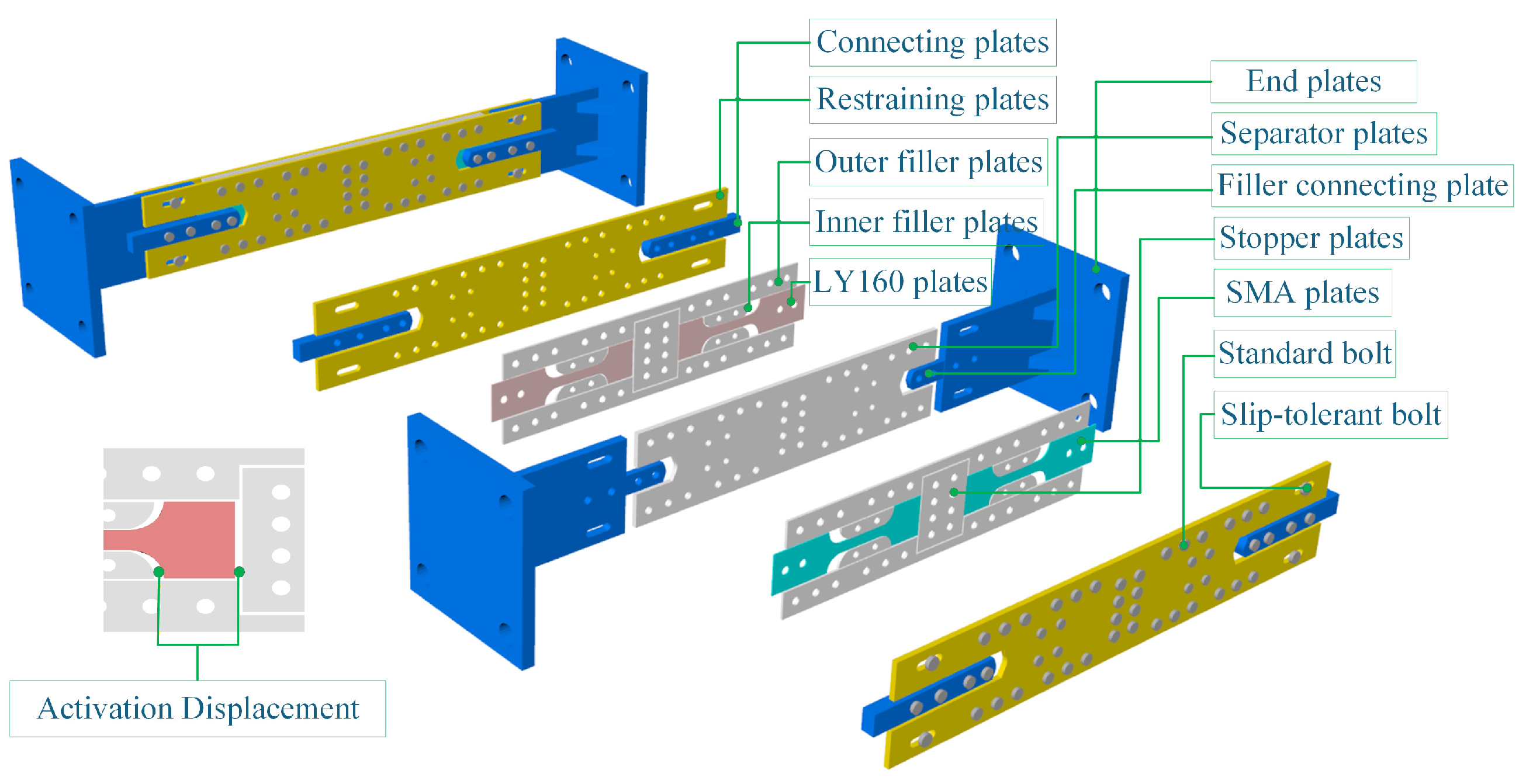
Figure 1. Schematic diagram of the SCDYB device.
Buildings 16 00960 g001
Figure 2. Schematic illustration of the working mechanism of the SCDYB.
Buildings 16 00960 g002
Figure 3. Mechanical model of the SCDYB.
Buildings 16 00960 g003
Figure 4. Benchmark frame model.
Buildings 16 00960 g004
Figure 5. Steel01 constitutive model and parameter values.
Buildings 16 00960 g005
Figure 6. Mode shape diagram.
Buildings 16 00960 g006
Figure 7. SelfCentering and Steel02 constitutive models and parameter values.
Buildings 16 00960 g007
Figure 8. Schematic illustration of the numerical model of the SCDYB.
Buildings 16 00960 g008
Figure 9. Comparison of hysteresis curves obtained from OpenSees simulations and experimental tests.
Buildings 16 00960 g009
Figure 10. Response spectra of the selected ground-motion records.
Buildings 16 00960 g010
Figure 11. Mean values of peak interstory drift ratios.
Buildings 16 00960 g011
Figure 12. Hysteresis curves of the SCDYB under different seismic hazard levels.
Buildings 16 00960 g012
Figure 13. Drift concentration factor.
Buildings 16 00960 g013
Figure 14. Mean residual story drifts.
Buildings 16 00960 g014
Figure 15. Time-history responses and hysteresis loops (GM.09).
Buildings 16 00960 g015
Figure 16. Effect of yield-displacement ratio on peak interstory drift ratios.
Buildings 16 00960 g016
Figure 17. Effect of stiffness ratio on peak interstory drift ratios.
Buildings 16 00960 g017
Figure 18. Residual displacements with varying activation-displacement ratios (β = 0.5).
Buildings 16 00960 g018
Figure 19. Interstory drift ratios with varying activation-displacement ratios (β = 0.5).
Buildings 16 00960 g019
Figure 20. Residual displacements with varying activation-displacement ratios (β = 1.0).
Buildings 16 00960 g020
Figure 21. Interstory drift ratios with varying activation-displacement ratios (β = 1.0).
Buildings 16 00960 g021
Table 1. Beam and column section dimensions of the benchmark frame model.
StoryColumn b1 × b2 × tBeam h × b × tw × tf
1~2400 × 400 × 20450 × 250 × 12 × 18
3~4400 × 400 × 15450 × 250 × 10 × 16
4~5400 × 400 × 10450 × 250 × 8 × 12
Table 2. Comparison of modal periods.
ComparisonFirst-Mode Period (s)Second-Mode Period (s)Third-Mode Period (s)
Ref. [42]2.170.730.40
Numerical model2.180.740.42
Table 3. Summary of the selected ground-motion records.
No.Earthquake EventDateStationMwRrup/km
GM.01Kern County1952LA-Hollywood Stor FF7.36117.75
GM.02Tabas_ Iran1978Boshrooyeh7.3528.79
GM.03Tabas_ Iran1978Sedeh7.35151.16
GM.04Loma Prieta1989SF-Diamond Heights6.9371.33
GM.05Northridge-011994LB-City Hall6.6957.68
GM.06Kocaeli_ Turkey1999Botas7.51127.05
GM.07Chi-Chi_ Taiwan1999CHY0887.6237.48
GM.08Chi-Chi_ Taiwan1999TTN0507.6289.28
GM.09Hector Mine1999San Bernardino-Del Rosa Wk Sta7.1396.91
GM.10Hector Mine1999San Bernardino-N Verdemont Sch7.13104.67
GM.11Chi-Chi_ Taiwan-021999TAP0525.9121.88
GM.12Chi-Chi_ Taiwan-031999TTN0316.273.73
GM.13Chuetsu-oki_ Japan2007GIF0216.8248.62
GM.14Iwate_ Japan2008AOM0246.9206.54
GM.15El Mayor-Cucapah_ Mexico2010Anza Borrego S.P.-Tierra Blan7.257.95
GM.16Tottori_ Japan2000KOC0166.61266.36
GM.17Tottori_ Japan2000MIE0136.61294.27
GM.18Darfield_ New Zealand2010MOLS7.0179.69
GM.19Darfield_ New Zealand2010SJFS7.0139.42
GM.20Christchurch_ New Zealand2011RDCS6.2172.19
GM.21Parkfield-02_ CA2004Bear Creek Road6.0180.94
GM.22El Mayor-Cucapah_ Mexico2010Salton Sea Wildlife Refuge7.257.97
Table 4. SCDYB parameter values.
ParameterValue
λyC0.51.01.52.0
ρe0.51.01.52.0
λGCB00.250.50.751.01.25
Disclaimer/Publisher’s Note: The statements, opinions and data contained in all publications are solely those of the individual author(s) and contributor(s) and not of MDPI and/or the editor(s). MDPI and/or the editor(s) disclaim responsibility for any injury to people or property resulting from any ideas, methods, instructions or products referred to in the content.