Article

Experimental Study on Axially Loaded Reinforced Concrete Columns Strengthened with Steel Cage

by
Aleksandar Landović
1,
Anka Starčev-Ćurčin
2,*,
Miloš Šešlija
2,* and
Danijel Kukaras
2
1
Faculty of Civil Engineering Subotica, University of Novi Sad, Kozaračka 2a, 24000 Subotica, Serbia
2
Faculty of Technical Sciences, University of Novi Sad, 21000 Novi Sad, Serbia
*
Authors to whom correspondence should be addressed.
Buildings 2026, 16(4), 882; https://doi.org/10.3390/buildings16040882
Submission received: 26 January 2026 / Revised: 18 February 2026 / Accepted: 20 February 2026 / Published: 23 February 2026

Abstract

The presented study investigates the structural behavior of reinforced concrete (RC) columns strengthened using an external steel cage and an additional concrete infill layer. An experimental program was conducted on short RC columns subjected to axial compressive force. A total of eleven columns were tested, including five plain RC and six strengthened specimens. The objective of the research was to evaluate the load-bearing capacity, failure mechanisms, and composite interaction between the steel cage, the infill concrete, and the original RC column. Two different distances between battens were considered in order to evaluate whether the number of batten plates significantly influences the efficiency of strengthening. The experimental results show that the proposed strengthening technique leads to an increase in axial capacity compared to unstrengthened specimens. Also, the variation in batten spacing within the investigated range has a negligible effect on the ultimate load. Failure was governed by cracking and bond deterioration in the infill layer, followed by progressive loss of composite action. The results indicate that the strengthening performance is primarily controlled by the properties of the infill concrete and the confinement mechanism, rather than by the spacing of the steel battens. The application of EN 1994-1-1 and EN 1998-3 in predicting the axial capacity of strengthened columns showed a good relation between experimental results and code calculations.

1. Introduction

Many reinforced concrete (RC) buildings undergo degradation or damage due to various factors, and their functions change over time. Increased loads, poor maintenance, a more hostile atmosphere, etc., frequently cause RC components to deteriorate. An older RC construction frequently lacks adequate earthquake protection due to increased requirements by updated seismic regulations. The load-bearing components must be strengthened since the forces in the structures are increased in each of the mentioned situations. In the case of the RC columns with the rectangular and square-shaped cross-section, a steel cage made from four angles interconnected with horizontal and/or diagonal battens can be positioned across the column’s whole height. This application makes use of four longitudinal steel angles (which are fastened at the corners) along the RC column, as well as orthogonal steel strips that are welded to the longitudinal angles to create a steel cage. The small gap between the RC column and the steel cage is filled with additional high-strength cement mortar or epoxy grout to form a complete composite cross-section. Additionally, before welding, battens might be preheated to provide the column with a positive confinement. Even though engineering manuals describe the use of angles and battens to strengthen RC columns [1,2], most of the contributing factors are frequently overlooked in current design practice.
Steel angles and battens create confinement pressures in the concrete core during compression, increasing load-bearing capacity, as it has been observed in [3,4,5,6]. Because of the composite action between concrete and the steel cage, the hoop stress condition is formed, which enhances concrete compressive strength while the concrete column keeps the steel elements from buckling inward [7]. Depending on the structural characteristics of the column-to-beam joint, the longitudinal angles may contribute to axial and flexural strength or just provide a confinement effect [8]. Also, the influence of different Poisson’s ratios for steel and concrete can be diminished if the load is applied only on the concrete part of the composite cross-section [9]. In that case, the steel cage only provides a confinement effect, which contributes to the axial strength of the concrete.
RC columns strengthened with steel angles linked by steel batten plates have been the subject of several investigations throughout the years. Strengthened RC columns under axial compressive loading have been the subject of multiple experimental investigations [7,10,11], while the behavior of reinforced columns under combined axial and bending stresses has been investigated experimentally in [12,13]. It has also been investigated how the beam–column junction affects the overall behavior of axially loaded RC columns strengthened by steel caging [14]. Adding capitals that are welded to the steel cage and in contact with the beam is one way to solve the beam–column joint [15]. Impact of the batten arrangement on the performance of axially loaded reinforced concrete columns strengthened with a steel cage is presented in [16]. Analyses of the specimen’s behavior and failure mechanism, as well as an increase in the reinforced column’s strength and ductility, are among the outcomes of the experimental investigations reported in the mentioned references. It has been noted that in columns without capitals at the ends, the cement mortar plays a significant role in the load transmission between the concrete material and the steel cage. Also, the use of capitals significantly enhances the load transmission between the concrete and the strengthening steel, especially at the ends of the strengthened column, and the steel battens apply high confinement pressure to the concrete at the RC column ends. Based on the experimental testing and numerical modeling using finite element analysis, numerous formulations have been proposed to determine the load-bearing capacity of an RC column strengthened using steel angles and battens [3,17,18,19]. Eurocode 4 [20] has no recommendation for direct application to an RC column strengthened with steel caging. However, the strengthened RC column could be assumed to behave similarly to a composite steel–concrete column, and Adam et al. [8,21] proposed using Eurocode 4 to estimate the ultimate load of an axially loaded steel-caged RC column. Lately, X-type batten steel plates and lightweight alkali-activated slag concrete have been used to improve the load-bearing capacity of existing RC columns [22].
One other method to increase the load-bearing capacity of the RC column is external jacketing using concrete and transverse reinforcement [23]. High-performance (HP) concrete and fiber-reinforced concrete (FRC) have been used to improve existing reinforced concrete elements, such as columns, beams, and beam–column joints. Cassese et al. presented experimental results on RC columns strengthened with HP-FRC jacket under concentric and eccentric compressive loads [24]. Additionally, [25] presents the strengthening of reinforced concrete columns using an ultra-high performance (UHP) FRC jacket. The findings indicate that all of the strengthened specimens had a brittle failure. Numerical analyses presented in [26] have been carried out to evaluate the impact of the jacket’s thickness on the load-bearing capacity of the RC column strengthened using a UHP-FRC jacket. The study’s findings show that the strength and stiffness of RC columns may be significantly increased using UHP-FRC. Although UHP concrete has high compressive strength, it is also highly brittle fracture.
The influence of concrete element size is important to evaluate when determining the bearing capacity of a concrete member under various loading conditions. A concrete specimen often demonstrates greater ductility at a small size, but at a sufficiently large scale, it shows brittle behavior [27,28]. Because of the size effect, a small-scale column may have different structural behavior than a full-scale column. Additionally, a size effect must also be used because quasi-brittle materials, such as concrete, fail through the formation and propagation of cracks. At small scales, the behavior of quasi-brittle materials aligns with strength-based theories governed by yield stress or material strength, whereas at larger scales, linear elastic fracture mechanics, which is defined by material strength and fracture energy, becomes more appropriate [29]. With appropriate geometric scaling of all test specimen components, such as the maximum aggregate size, cover thickness, and reinforcement arrangement, a size effect could be practically eliminated [30]. Taking geometric scaling guidelines into account, in the presented research, a geometric similarity was employed in a 1 by 3 ratio, where all dimensions of the specimens were scaled three times.
Previous studies have demonstrated the effectiveness of steel cages or concrete jacketing when applied separately, but experimental research on the structural behavior of RC columns strengthened using a combined steel cage and high-strength concrete infill system is limited. Existing research investigates either steel-only confinement systems or thick concrete jackets, while the interaction between a thin infill layer and an external steel cage remains insufficiently investigated. Therefore, the present study extends existing knowledge by experimentally examining the composite interaction of three parts of the composite cross-section by identifying the contribution of each part to the column’s axial capacity.
The novelty of the present study is in the experimental investigation of a three-component composite strengthening system for reinforced concrete columns, consisting of the basic RC column, an external steel cage, and an additional high-strength concrete infill layer. Most existing studies primarily focus either on steel jacketing without infill or on concrete jacketing without external steel confinement. The proposed solution combines both solutions into a single composite system. Furthermore, in previous experimental investigations, the load is typically applied directly to the steel jacket or is distributed over the entire composite section, while in the presented study, the load is applied only to the basic RC column. This approach allows assessment of the force transfer between the RC core, the infill concrete, and the steel cage. The experimental quantification of the load-sharing mechanism between the three components, which is based on measured strains, enables direct evaluation of the actual composite action. Finally, the study provides experimental validation of the applicability of existing design codes (EN 1994-1-1 [20], EN 1998-3 [1], and AISC 360 [31]) for this specific strengthening configuration, which is not explicitly covered in current codes.
The experimental program presented in this study has limitations that should be acknowledged. First, all specimens were tested as short, axially loaded columns, and therefore, the influence of global buckling, load eccentricity, and second-order effects was not considered. Therefore, the results are applicable to compact columns subjected to axial compressive force. Second, the investigation was limited to short-term loading, while long-term effects such as creep and shrinkage of the concrete were not included. The long-term effects may influence the bond between the concrete infill, steel cage, and basic RC column, which can influence the durability of the composite action. Third, only two values of batten spacing and one geometry of steel angles were examined. Although the results indicate a relatively minor influence of batten spacing within the tested range, different configurations, thicknesses, and steel grades may lead to different confinement efficiency. Finally, the column models were tested at a reduced size, and the scale effects may still influence cracking behavior and failure modes compared to full-scale columns. Finally, the column models were tested at a reduced scale, and while geometric similarity was preserved, scale effects may still affect cracking behavior and failure modes in comparison to full-scale columns.
The presented study is a part of research on strengthening RC columns using various methods, which is partially presented in [32].

2. Experimental Program

2.1. Test Specimens

The dimensions of the column models were chosen to correspond with a real concrete structure with a ratio of 1 by 3, i.e., the column model is 3 times smaller compared with a real structure column. The scale of the test models was designed to account for the constraints of the laboratory testing equipment, with the largest model potentially reaching one meter in height. Then, an aspect ratio of 1 by 3 was calculated assuming that a typical RC building has a 270 cm high story. Other test specimen characteristics, including column cross-section dimensions, steel angle dimensions and thickness, rebar diameter, and fresh concrete aggregate sizes, were properly scaled.
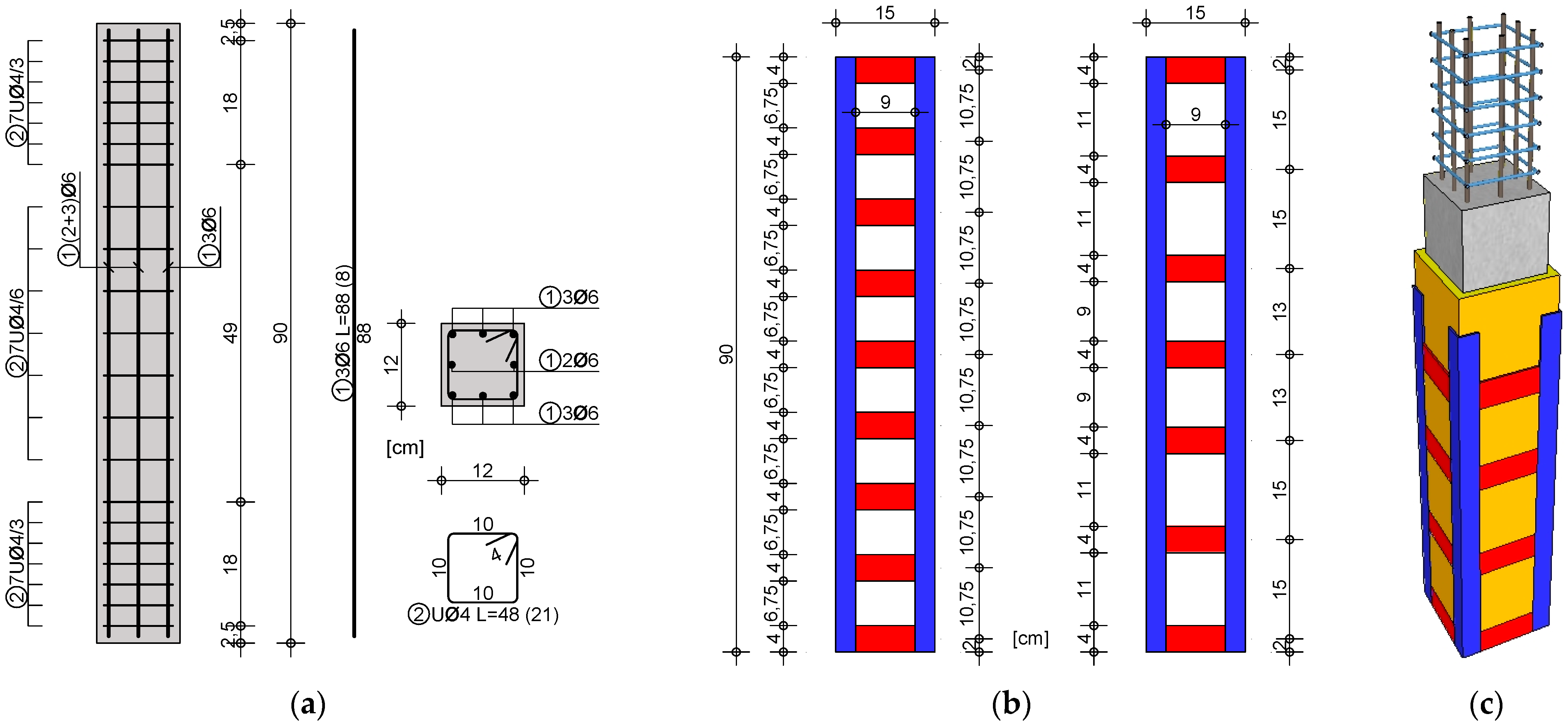
A total of 11 columns, separated into three groups, were tested under axial compressive loading. The first group, containing five models of plane RC columns, was the control specimens (Label S0x). The next two groups, containing three models, were RC columns strengthened using steel angles and battens (Labels L0x and L5x). In all series, x represents the specimen serial number. The columns, both strengthened and un-strengthened, were 90 cm high and had a square cross-section measuring 12 by 12 cm. All of the columns were built using class C35/45 concrete. Columns were reinforced with eight 6 mm diameter bars and 4 mm closed stirrups. Stirrups were spaced 6 cm in the center and 3 cm at the top and bottom of the column height (Figure 1a).
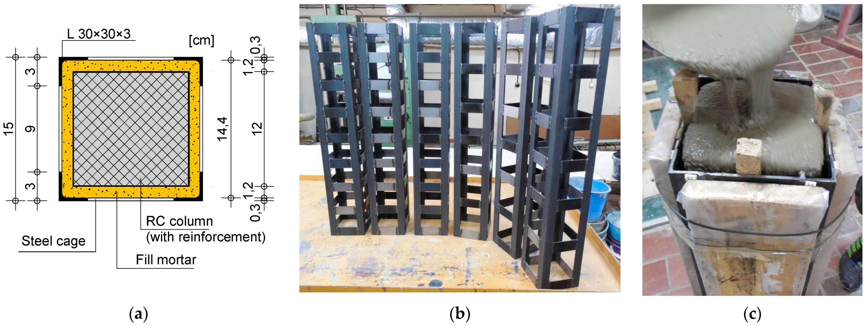
A model of an RC column was strengthened using a steel cage made from four steel angles and steel horizontal plates. A multi-part steel cage was formed from four hot-rolled L30 × 30 × 3 angles spaced 90 mm apart. The angles are connected by steel splice plates—battens, with the dimensions 90 by 40 mm and the thickness of 3 mm. The vertical position of the horizontal cross battens was varied for two cases, as shown in Figure 1b. For the first case, nine splice plates per side of the column were used, arranged at a spacing of 107.5 mm, while in the second case steel cage was made with seven splice plates per side at a spacing of 150 mm (Figure 1b). The batten spacing was chosen as a representative of the real structure application, appropriately scaled. Figure 1c shows a 3D section through the multi-part composite column formed by combining the concrete column, reinforcement, mortar infill, steel angles, and splice plates. The dimensions of the composite cross-section of the column after strengthening are presented in Figure 2a. The connection between the splice plates and the L-shaped flange profiles was made by butt welding using a 1/2V weld. The welds were not additionally treated by grinding. Figure 2b shows prepared steel cages. An RC column was pre-made and then placed inside the welded steel cage, and the remaining gap was filled with fresh concrete (Figure 2c). Before the fill concreting, the steel cages were cleaned with solvent to eliminate any corrosion, oil, or grease deposits. After strengthening, the columns were kept in a laboratory to air-dry at a constant temperature of 18 °C and 60% humidity.
To ensure effective composite action between the concrete and steel, the space between the cage and the RC column was filled with high-quality, fine-grained, expansive mortar. For filling all six strengthened columns, SikaGrout 212 (Sika, Serbia) was used. The compressive strength of the used material corresponds to concrete strength class C60/75.
The main characteristics of all tested specimens are summarized in Table 1, where a is the width of the square section, t is the wall thickness of the steel cage, L is the length of the specimen, respectively, and Nu is the test ultimate bearing capacity.

2.2. Material Properties

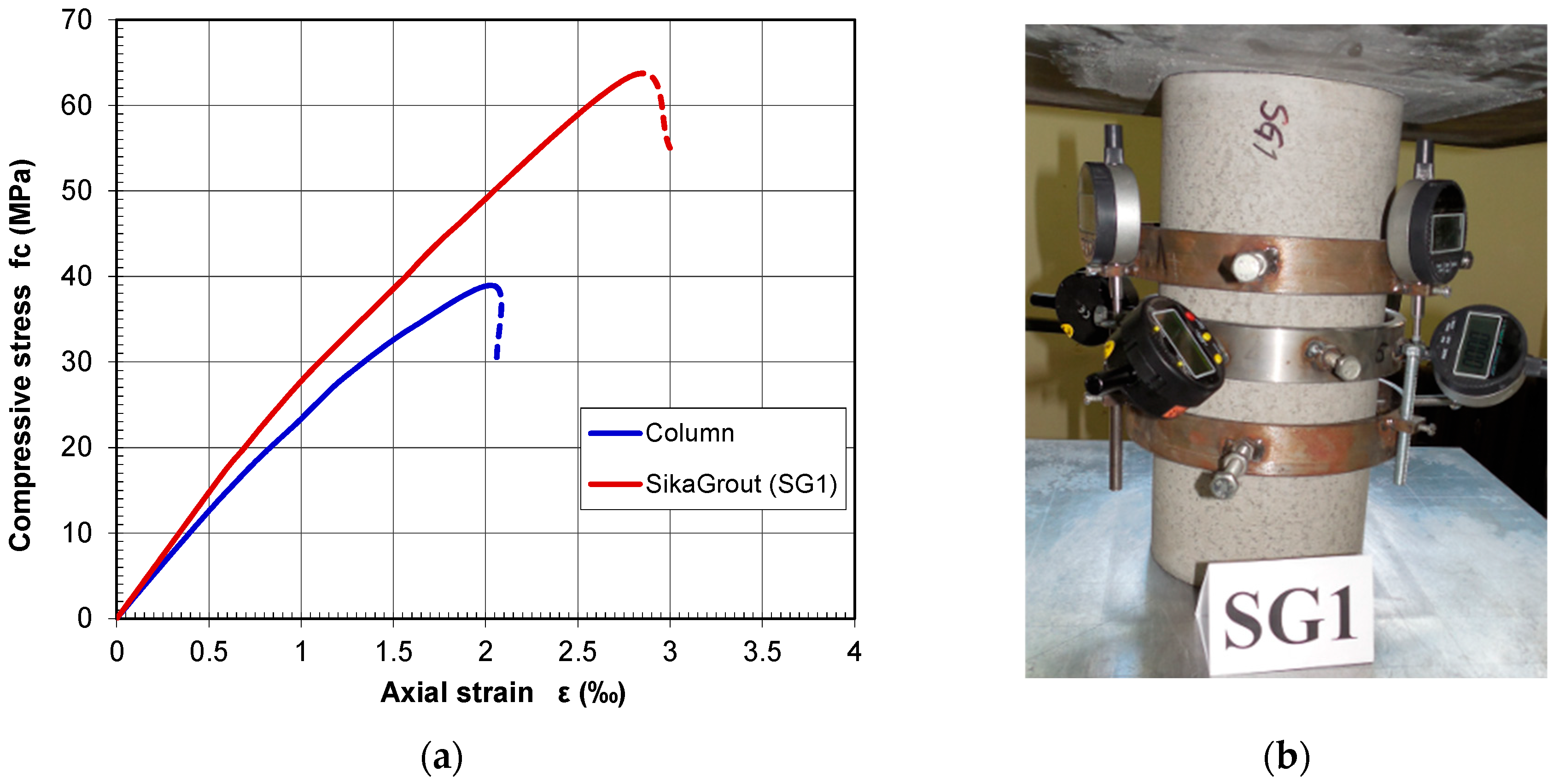
The materials used to prepare fresh concrete mix for the RC column models were: cement 443 kg/m3, fine aggregate (siliceous sand) 466 kg/m3, coarse aggregate (crushed carbonaceous rock) 1098 kg/m3, and water 250 kg/m3. The cement used for RC columns was CEM II/A-M 42.5R (Lafarge Beočin, Serbia). In addition to column manufacturing, six cubes with sides of 15 cm and three cylinders with a 15 cm diameter and 30 cm length were cast. All test specimens were cured under the same conditions as column specimens. Experiments to determine the mechanical characteristics of hardened concrete followed EN 12390 criteria. Table 2 shows the average values of compressive cube and cylinder strength, splitting tensile cube strength, static modulus of elasticity, Poisson’s ratio, and density. The noted parameters were tested two days before the testing of the column models, ensuring that the properties of the concrete were precisely known at the time of the experiment. Figure 3a shows representative compressive stress–strain curves for concrete used for RC columns and SikaGrout derived from load–displacement relationships observed during cylinder tests. Testing of the Young’s modulus and Poisson’s ratio using digital deflection gauges is presented in Figure 3b.
The properties of the reinforcement steel were experimentally determined on standard test coupons. The average yield strength (fsk) was 550 MPa with a tensile strength (fusk) of 650 MPa.
The angles and splice plates used for strengthening were manufactured from 3 mm thick steel. The splice plate was cut out from a mild steel sheet and welded to hot-rolled steel angles. Standard testing coupons were cut from the steel angles and tested in tension. The average yield strength (fy), ultimate tensile strength (fu), and Young’s modulus (Es) are 265 MPa, 378 MPa, and 200 GPa, respectively. In the presented study, residual stresses and initial geometric imperfections of the steel angles were neglected when calculating yield strength, as indicated in [33]. The assumption can be justified by the configuration of the structural elements of the strengthened column. The steel angles are restrained by the concrete infill and the basic RC column, which provides lateral support along the entire height of the steel member. This lateral support suppresses local buckling and limits the development of additional stresses caused by initial imperfections.

2.3. Test Setup

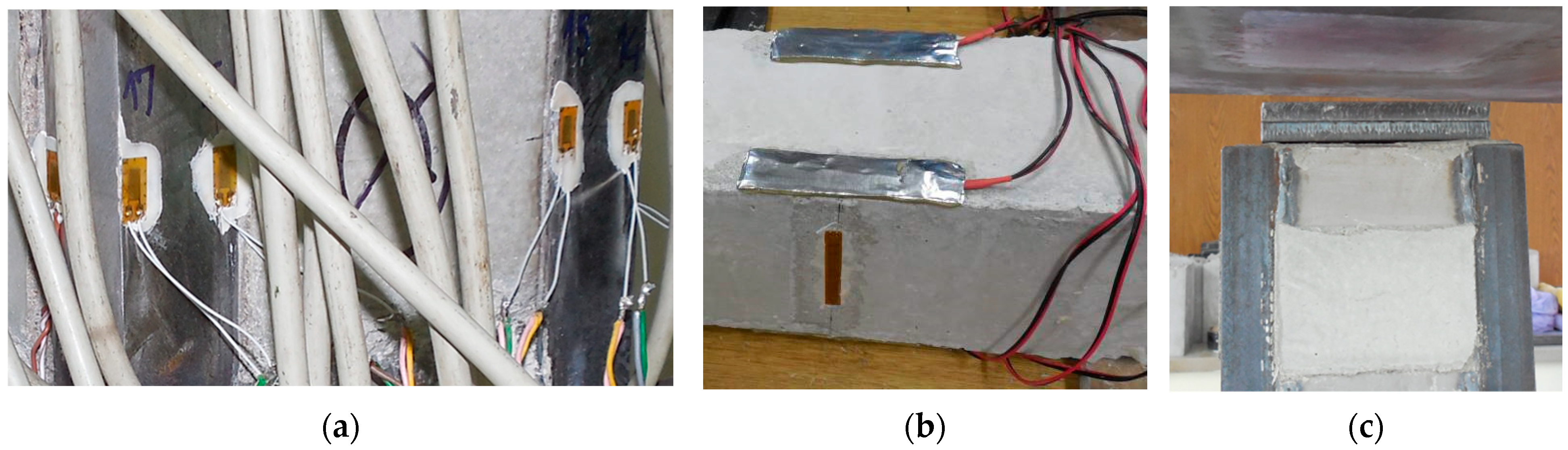
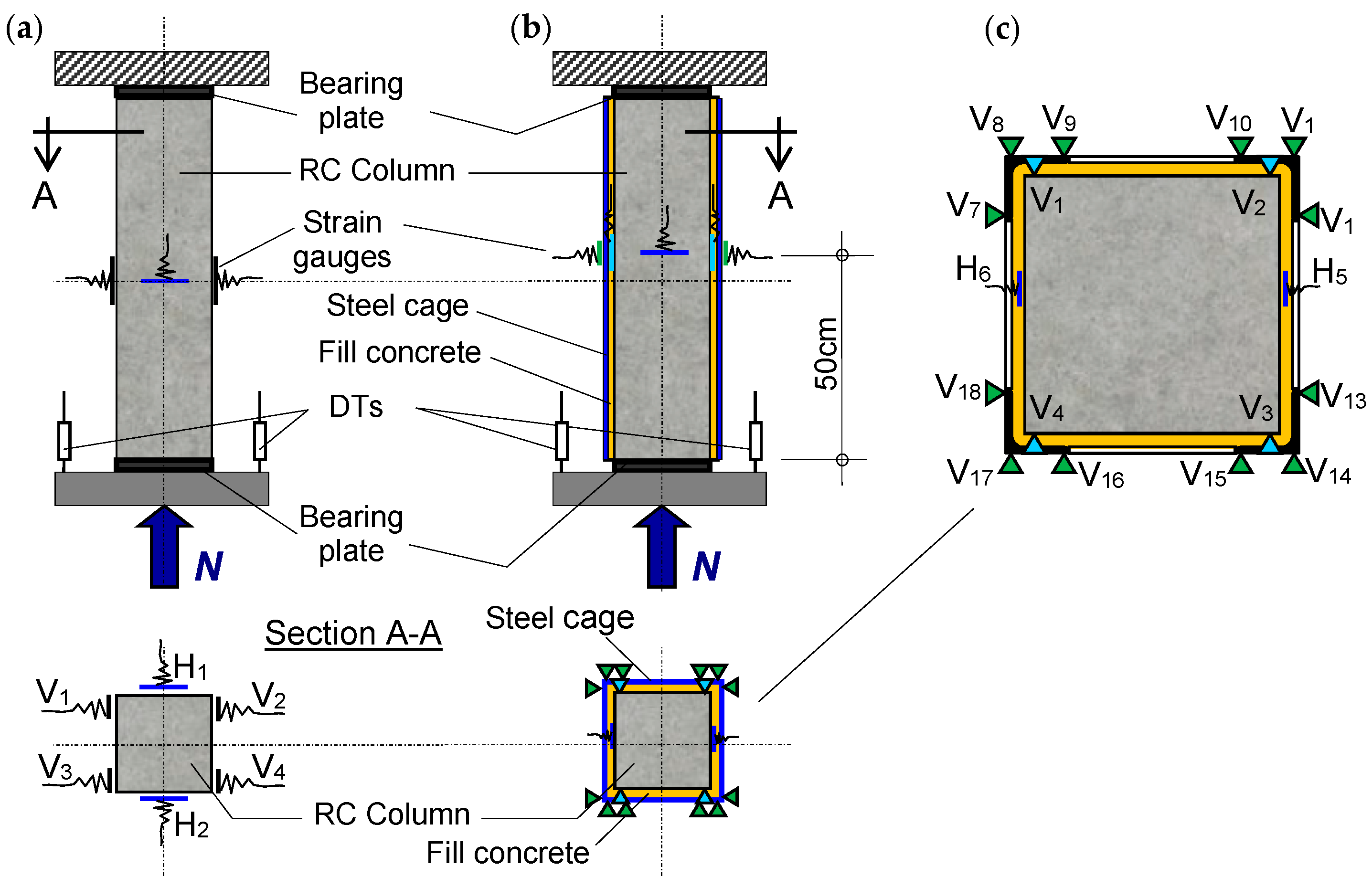
The experimental testing included measurement of local deformations (axial and lateral strains) and measurement of global deformation (the column’s shortening). A schematic view of the test setup is presented in Figure 4. In order to monitor strain changes at a section near the middle of the column’s height, strain gauges were symmetrically arranged around the column’s cross-section. Axial strain gauges were designated as V (vertical), while lateral strain gauges were designated as H (horizontal). Four vertical and two horizontal strain gauges were used on the plain (Figure 4a). For the columns strengthened with a steel cage, the measurement sections were located near the mid-height of the column, positioned so that the strain gauges were placed midway between the splice plates. Figure 4b shows the vertical position of the measurement sections. The testing sections of columns L0x and L5x were equipped with a total of 18 strain gauges. Four vertical and two horizontal strain gauges were installed on the RC column before fill concreting, while three vertical strain gauges were installed on each steel angle (Figure 4c and Figure 5a). The measurement of specific strains in the direction of the principal stresses on the concrete specimens was carried out using HBM K-LY41-50/120 strain gauges with a gauge length of 50 mm, while the strains on the steel angles were measured using HBM K-LY41-6/120 gauges with a gauge length of 6 mm.
Strain gauges placed on the RC column inside the steel cage were protected using ABM75 elastic protection cover manufactured by HBM (Figure 5b). Conduction wires from the strain gauges were guided through the infill concrete to the top of the specimen and connected to the acquisition system. Additionally, two symmetrically positioned displacement transducers (DTs) were used to detect the axial deformations (shortening) of specimens, as shown in Figure 4a,b. Throughout the loading process, all instruments’ readings were automatically recorded. For all columns, the analysis included registration of changes in stresses and deformations, ultimate strength, and shape of global deformation at maximal capacity, and force engagement of the different parts of the composite cross-section. In addition to ultimate force and deformation, the analysis of RC models included the force that caused concrete cracking, fracture progress, and crack propagation. This study focused on short-term loads, while long-term effects such as concrete creep and shrinkage were not considered.
A hydraulic testing machine with a 2000 kN capacity was used for all of the tests. The load on the test specimen was applied in an upward direction. The axial loads on the specimens were imposed across the top and bottom steel bearing plates using the passive composite column loading technique. The bearing plates (12 by 12 cm in dimensions) on strengthened specimens allowed only the central RC column to be loaded directly (Figure 5c). Using bearing plates, the conditions of a real structure strengthened by the steel cage were simulated, where the load transfer occurs solely over the concrete column. This approach also eliminated the influence of surface irregularities of the concrete on load introduction.
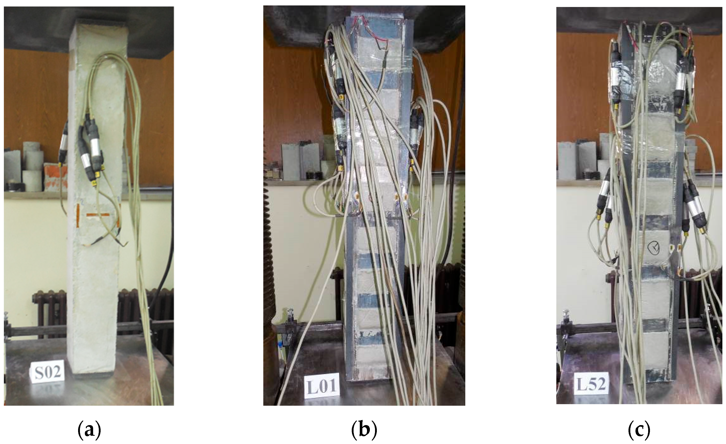
Every column was loaded with increasing axial force up until failure. The hydraulic press was operated using a force control technique with a value of each load step that corresponds to one-twentieth of the predicted load-bearing capacity. Each load step was sustained for about 5 min. The loading process was stopped when the weld failure of the steel cage was registered or when the applied force dropped below the peak value. Figure 6 shows the column specimens of each group just before experimental testing.

3. Experimental Results

3.1. Reinforced Concrete Columns

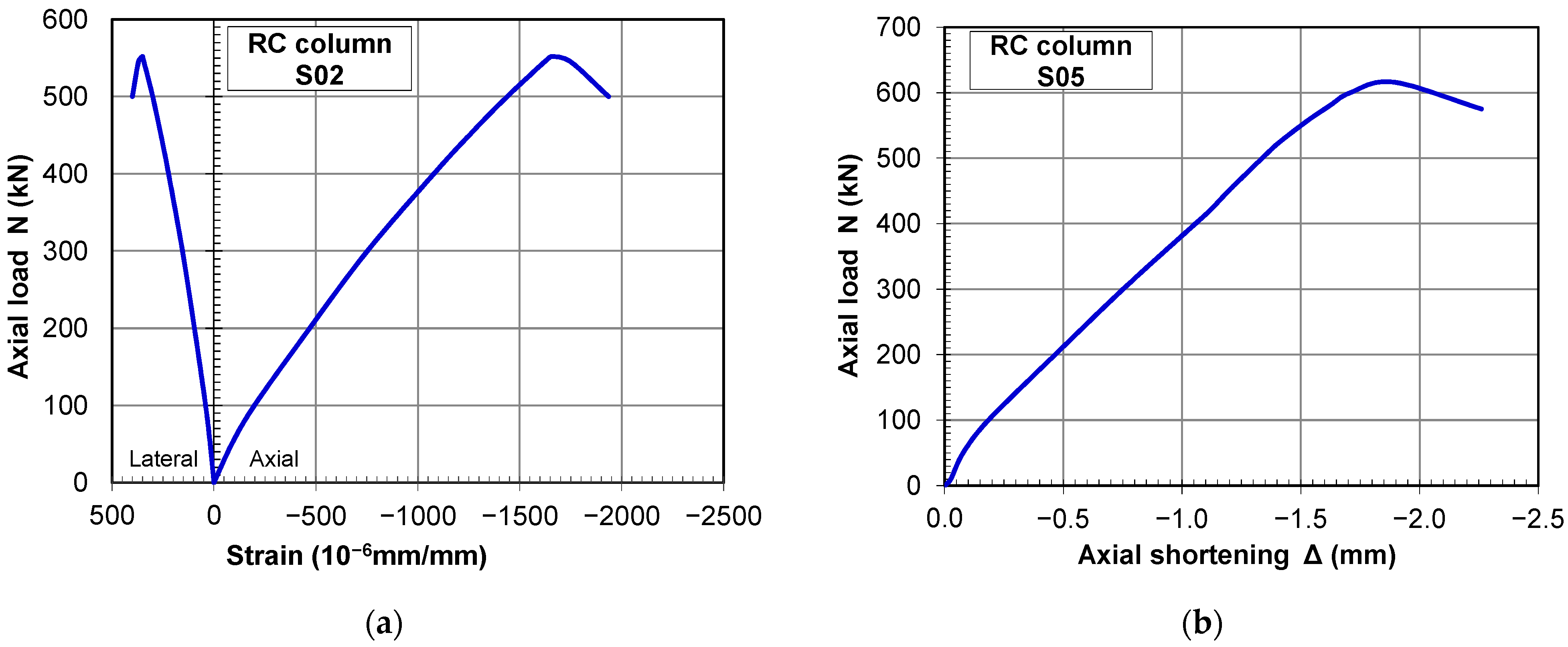
Five axially loaded, plain RC specimens were tested in order to compare the results and to determine the effects of the strengthening. The registered load versus stresses and load versus displacement curves are displayed in the diagrams in Figure 7. From examining the diagram in Figure 7a, it can be noticed that column models exhibited essentially linear behavior all the way through the loading procedure up to the ultimate strength. At failure, the longitudinal strains were around 2.0‰, which is an expected value for axially compressed concrete columns.
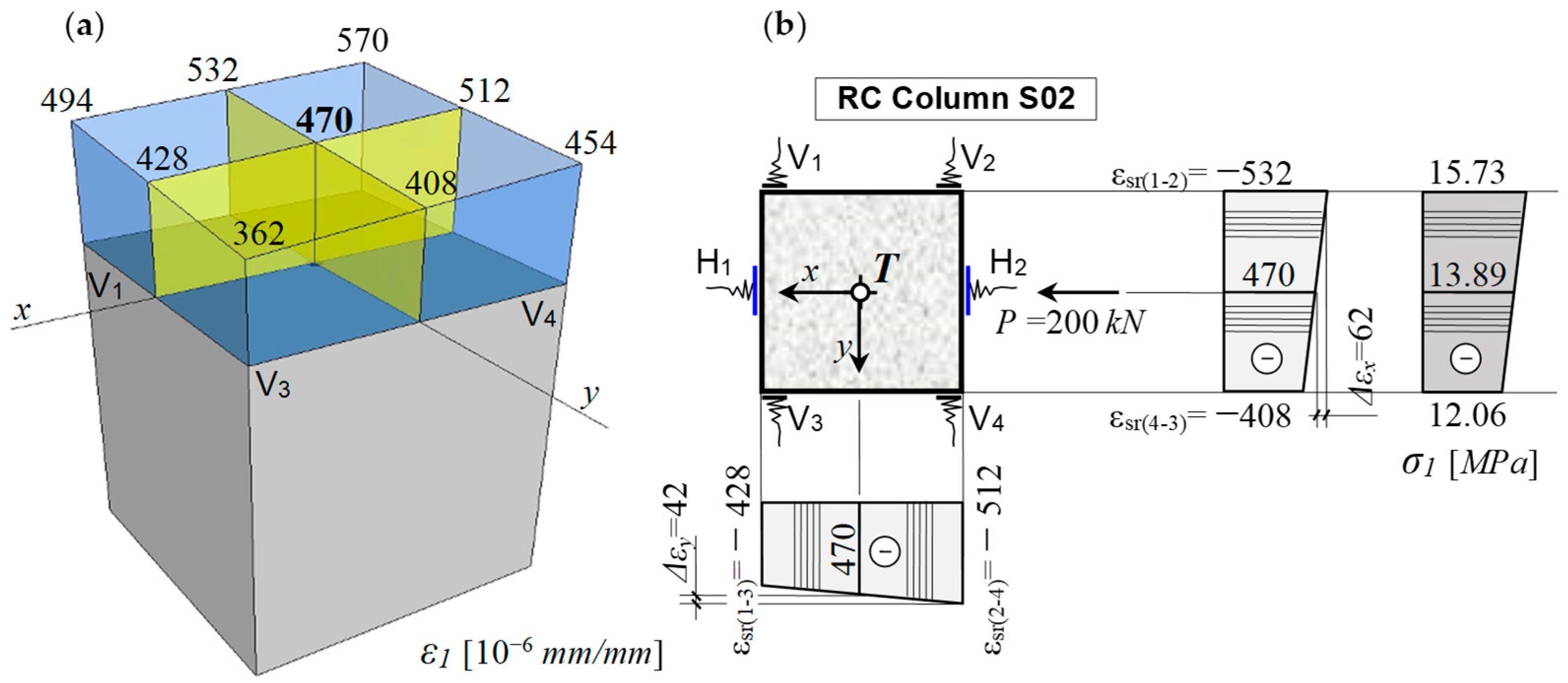
The stress–strain analysis was conducted for a load of a concentrated compressive force of P = 200 kN at the cross-section located at mid-height of the column. The ratio between the applied load from the analysis and its ultimate value, P/Pu = 0.362, approximately corresponds to 40% of the compressive strength of the specimen. For this level of compressive stress and the corresponding strains, the secant modulus of elasticity was defined in accordance with Eurocode 2. The state of longitudinal strains in column model S02, as well as the method for determining the centroid stress and strain, is presented in Figure 8a. In the stress analysis, the specific compressive strains were taken in absolute values. From the diagram in Figure 8b, it can be observed that the difference between the strains at opposite points and those at the centroid of the cross-section is relatively small. This indicates that the column model was loaded concentrically and that bending moments resulting from load eccentricity were minimal. Therefore, it can be considered that the specimen was tested as a purely axially loaded column, which was the intended objective of the experiment.
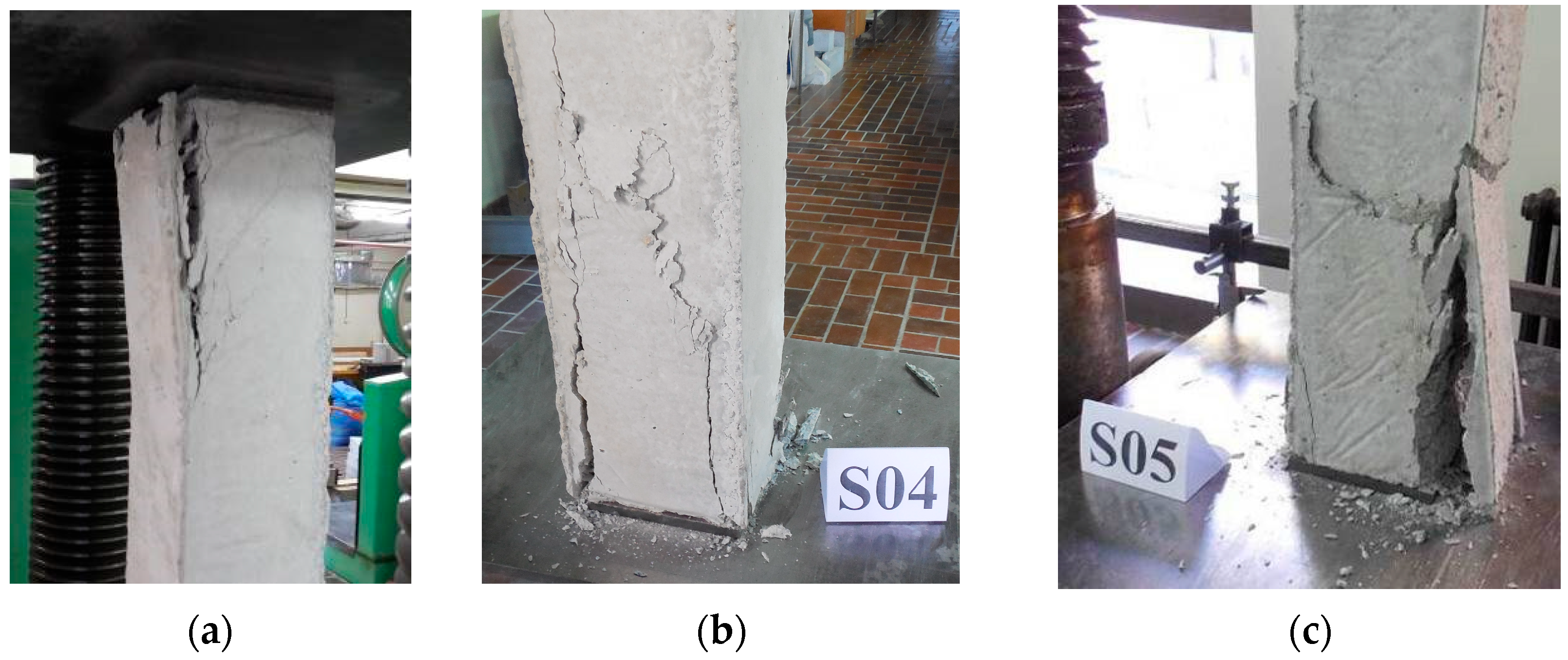
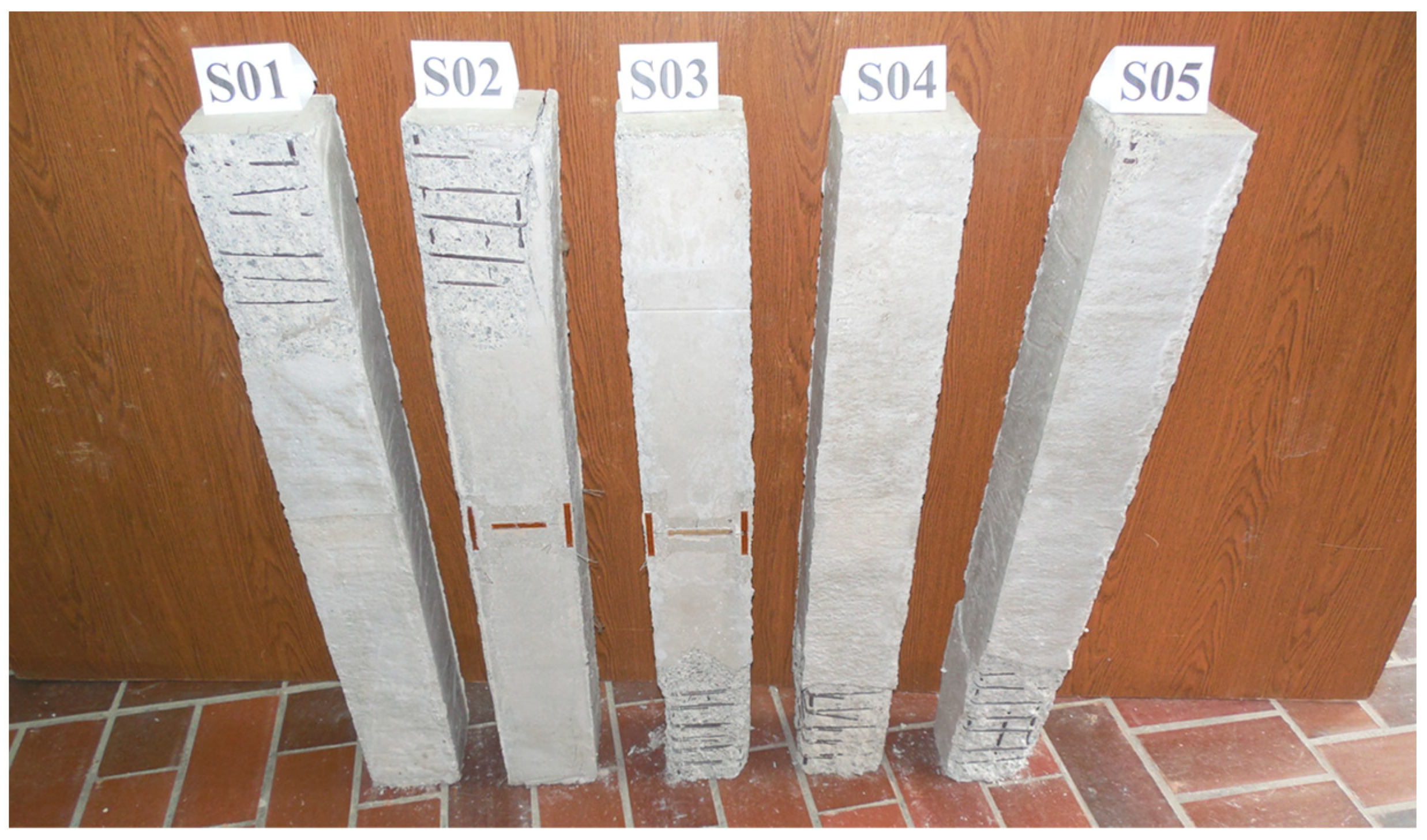
First longitudinal fractures were registered at the ends of columns in plain RC specimens when loaded to approximately 90% of the ultimate force. For that load, lateral stresses and strains in concrete met the axial tension limit with a strain of 0.25‰. The failure of the plain RC specimens was caused by fracture formation and breaking of the concrete around the point of force application, as seen in Figure 9a–c. In the areas of high stress near the steel bearing plates, the fractures penetrated the aggregate and cement. The frictional confinement prevented the formation of splitting fractures under the steel loading plate. Because of the crack formation, an inverted pyramid developed under the load-bearing plate at both ends of the column, and the column collapsed. All specimens began to fracture at both ends of the column; however, Figure 8 shows that only one end had significant crack development and loss of cross-section as a result of concrete splitting and breaking. Table 1 shows the values of ultimate load forces for columns from the control group, while Table 3 provides the mean value of registered forces, standard deviation of the results (Sn), and coefficient of variation (COV). All test models of plain RC columns are shown in Figure 10.

3.2. Strengthened Columns

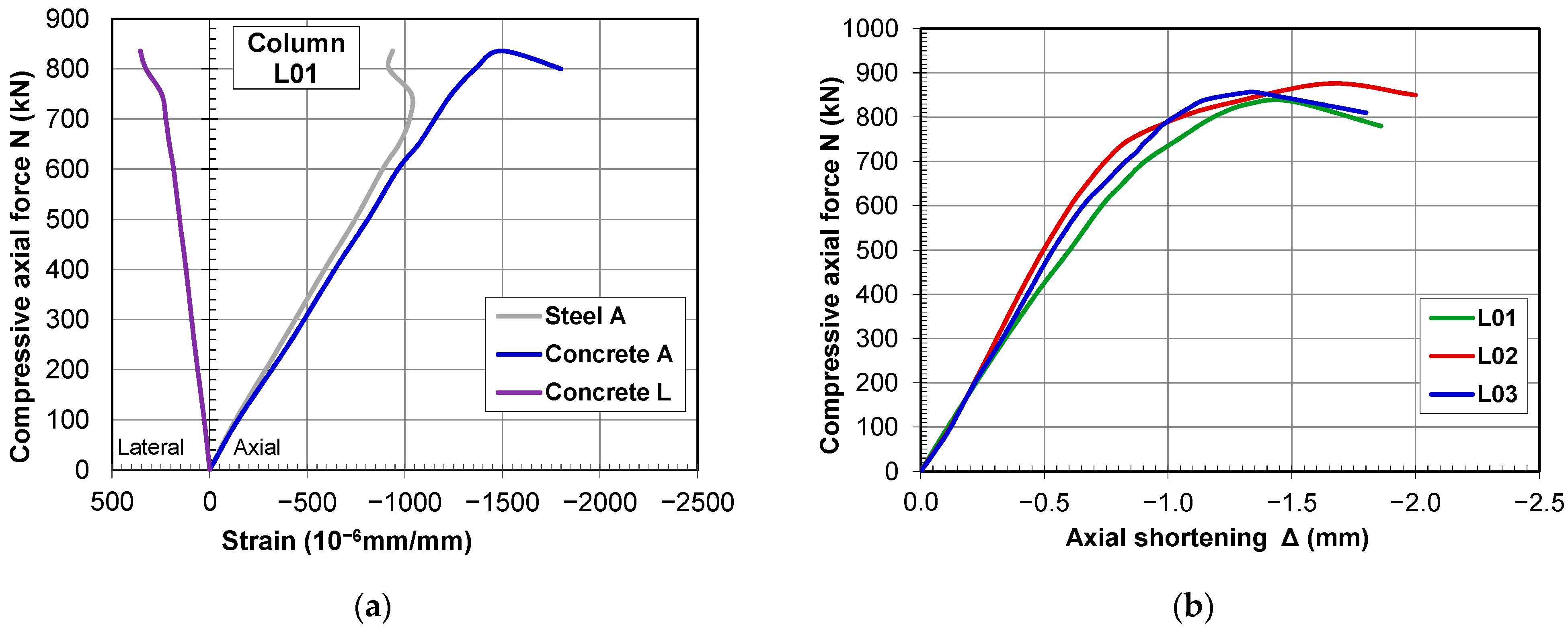
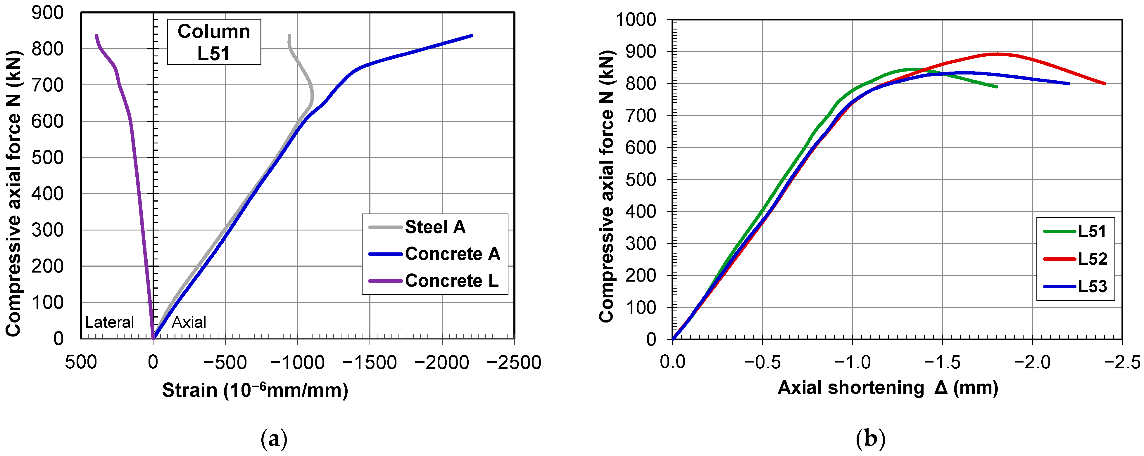
To ensure that findings could be directly compared, testing of all strengthened models was carried out with comparable experiment program stages as for the models of the control group. This made it possible to directly evaluate the effectiveness of the steel cage strengthening technique for RC columns. Additionally, strengthened models may be cross-compared, allowing for the evaluation of the impact of different distances between horizontal battens. Diagrams showing the force to axial shortening for reinforced specimens and the relation of compression axial force to longitudinal and lateral stresses are shown in Figure 11 and Figure 12.
From the stress–strain diagrams for the L0x specimens, it can be observed that, within the service load range, the longitudinal specific strains in the steel angles and in the RC column have very close values, which indicates that a good composite action was achieved. A relatively small deviation between the strains in steel and concrete was recorded, up to 80% of the specimen’s ultimate load. At a load of approximately P = 690 kN, the transverse strain of 0.2‰ was reached in the basic RC column, corresponding to the tensile strength limit of the concrete, and at nearly the same moment, the steel strain of 1‰ was reached. With a further increase in load, a more pronounced divergence between the measured deformations in the steel and concrete occurred. The differing values of specific strains in concrete and steel indicate that the bond within the composite cross-section began to deteriorate. Once the tensile capacity of the infill concrete was reached, longitudinal cracks developed in the SikaGrout infill, which affected the force transfer between the RC column, the infill, and the steel cage. This is also reflected in the strain readings: the steel strain showed only a very small increase up to failure, while the concrete strain exhibited a significantly larger growth. The divergence between the concrete and steel strains became pronounced in the domain of ultimate loading and immediately before the specimen’s failure. At higher stress levels, differences in strain values in concrete and steel led to the conclusion that slippage between composite cross-section parts had occurred.
Similar behavior was registered for the L5x specimens. The longitudinal specific strains within the service load range in the steel profiles and in the RC column have almost identical values, which indicates very good composite action of the cross-section for the loads up to 70% of the specimen’s failure load. For the load of around P = 660 kN, the transverse strain corresponding to the tensile stress limit in the concrete of the basic RC column was reached, and the steel strain of 1‰ was also attained. With further increase in load, a more pronounced divergence occurred between the measured deformations in the steel and in the concrete, similar to the L0x group. The differing values of specific strains in concrete and steel are a consequence of the deterioration of the bond between the components of the composite cross-section.
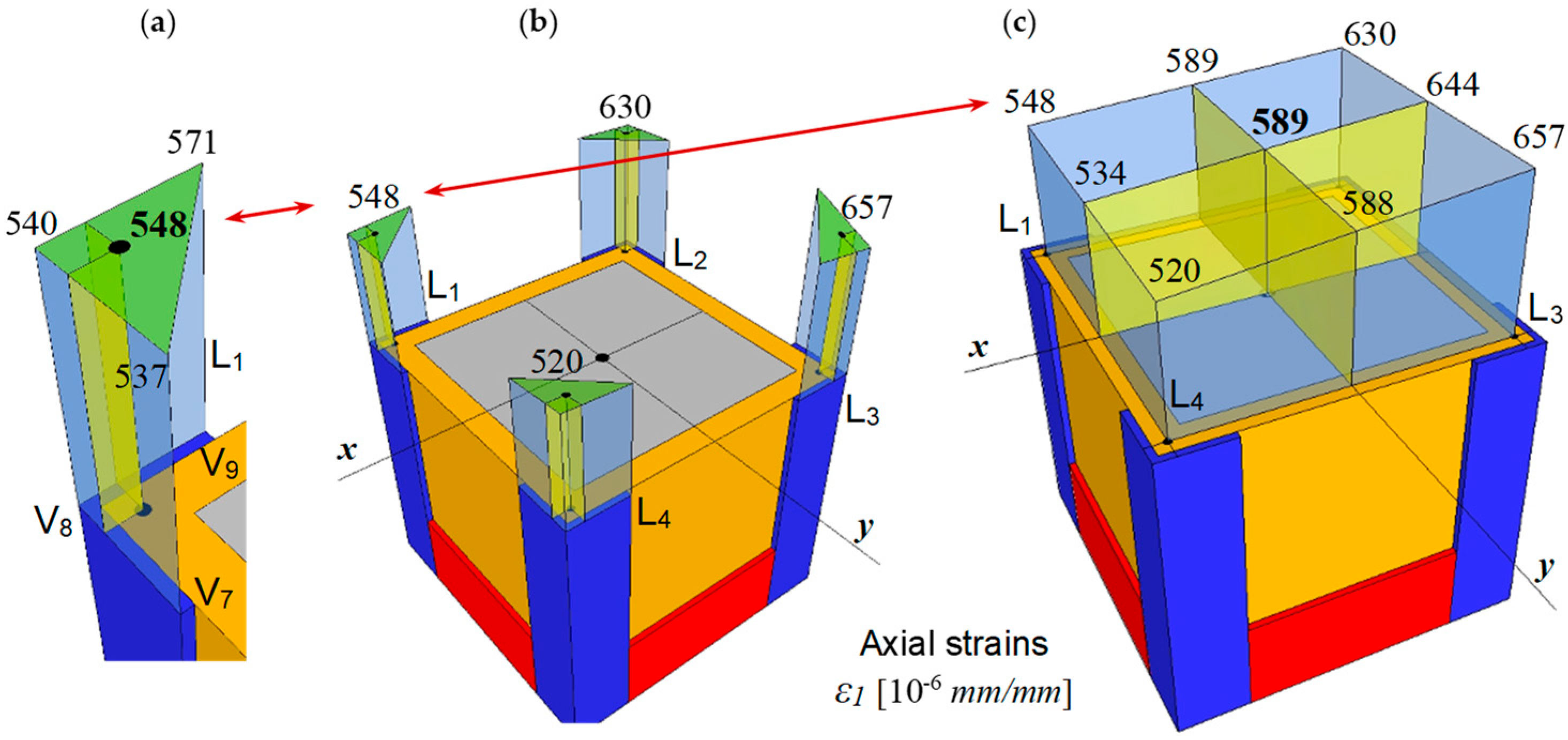
The stress–strain analysis was carried out for a concentrated compressive load of P = 400 kN. The ratio between the applied load and its ultimate value corresponds approximately to 50% of the specimen’s capacity, which is in the domain of exploitation loads. The principle of determining the centroidal strain from the three measured values (V7, V8, and V9) on steel angle L1 is shown in Figure 13a, while Figure 13b presents the specific strain values at the centroids of profiles L1–L4. Based on the strains of the individual profiles, the centroidal strain of the group of profiles was determined, as illustrated in Figure 13c. These centroidal values are shown in the diagrams in Figure 11a. Analysis of the values in Figure 13c shows that the difference between the strains at opposite points and those at the centroid is relatively small, indicating that the bending moments caused by load eccentricity were minimal.
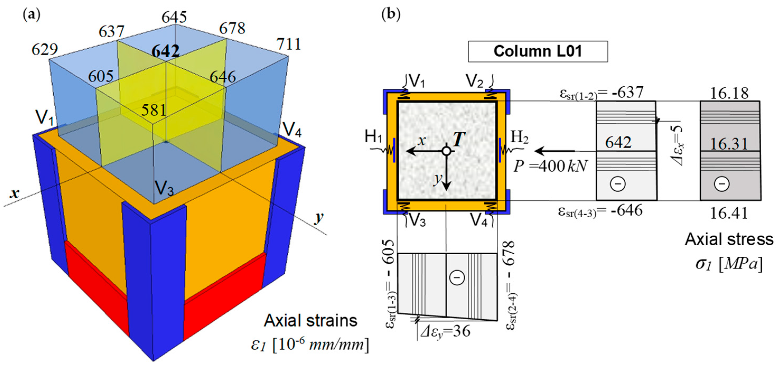
Figure 14a shows the method used to determine the centroidal strains in the concrete of the RC column. As with the steel parts of the cross-section, it can be observed that the difference between the strains at opposite points and those at the centroid is relatively small (Figure 14b), which confirms that the column model was loaded concentrically and that the bending moments resulting from load eccentricity were minimal. All of this indicates that the specimen can be considered as a purely axially loaded column, which was the main objective of the experiment.
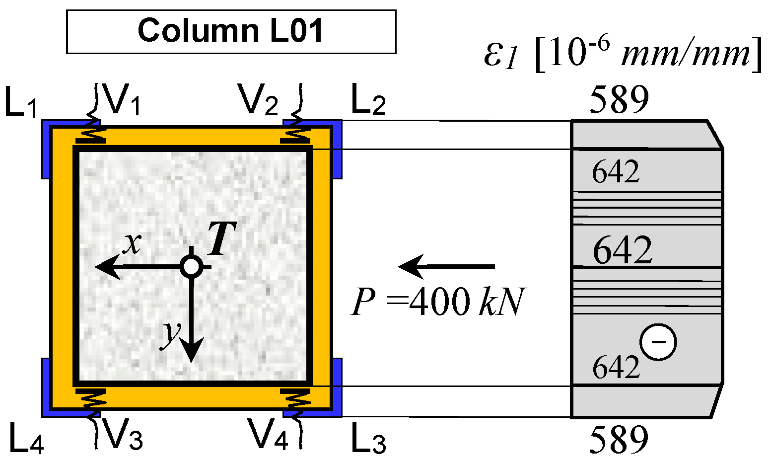
The engagement of the individual components of the composite three-part cross-section (“Concrete–Infill–Angles”) is presented through the force balance at the service load level of P = 400 kN. Figure 15 shows the centroidal values of the longitudinal (axial) strains in the concrete and in the steel.
The load in the column is distributed among the individual parts of the cross-section proportionally to their axial stiffness and the measured specific strain. The portion of the axial force carried by each part of the cross-section (Pi) is determined using the expression Pi = εi·Ei·Ai, where εi is the measured longitudinal specific strain, Ei is the elastic modulus, and Ai is the area for the corresponding part of the cross-section. The elastic modulus of the RC column corresponds to the secant modulus at the load level equal to 40% of the compressive strength of column model S03. The force balance calculation for the L01 column model is given in Table 4.
From the presented results, it can be seen that the basic RC column carries 54.1%, the infill 26.3%, and the steel angles 19.6% of the total load acting on the composite column. The balance of these forces gives a total value of Peff = 420.3 kN, which is approximately 5% higher than the applied load of P = 400 kN. The presented stress–strain analysis refers to column model L01, which was selected as the representative of the group. The same analysis was carried out for models L02 and L03, yielding similar results.
The force balance calculation for the L51 column model is given in Table 5. Based on the presented analysis, it can be observed that, in this group, of the total load applied to the specimen, the basic RC column carries 54.3%, the infill 26.2%, and the steel angles 19.5%, which are ratios almost identical to those obtained for the models in the previous group. The force balance calculation gives a total effective load of Peff = 453.9 kN, which is approximately 13% higher than the applied load of P = 400 kN. As for the previous group, the same study was conducted for column models L52 and L53 with comparable results.
Small differences between the forces recorded on the testing machine and the forces obtained from the force-balance calculation were likely influenced by several factors. The main causes of the discrepancies could be in the values of the elastic moduli of both the column concrete and the SikaGrout infill. Another possible source of difference between the measured and calculated forces may be the cross-sectional areas of the individual components. The force-balance calculation was performed using the actual constructed areas, which is why the recorded deviations are relatively small, around 5% and 13% for the L0x and L5x group, respectively. This confirms the accuracy of the used assumptions, as well as the reliability of both the measurements on the column model and the measurements used to determine the elastic modulus.
Theoretical force distribution between the composite column’s parts determined using axial stiffness of individual components ( E i A i / E i A i ) gave that the basic RC column carries 52.6%, the infill 26.6%, and the steel angles 19.5%, which is very close to the distribution obtained using measured strains. The theoretical distribution assumes that all strains have the same value.
The behavior of the experimental specimen in these two groups corresponds most closely to the model in which the entire cross-section is assumed to be uniformly loaded. Although in the experiment the specimen was loaded solely over the central RC column, the small thickness of the infill allowed full transfer of force to the steel cage. The high mechanical properties of the SikaGrout contributed to a more uniform distribution of the load.
The diagrams in Figure 11b and Figure 12b comparatively present the relationship between the axial force and the longitudinal strain for all three column models for each group. It can be observed that the global behavior of all three models from one group is almost identical up to failure. The column models in both groups exhibit very similar failure loads and ultimate strains, as well as a nearly linear response up to a load of P = 700 kN, which corresponds to the load at which the tensile strain limit in the concrete is reached. With further increase in load, a more pronounced growth of deformation relative to the increase in force becomes noticeable. After reaching the ultimate load, the composite column cross-section was no longer able to sustain any additional increase in force, even though the deformation continued to grow.
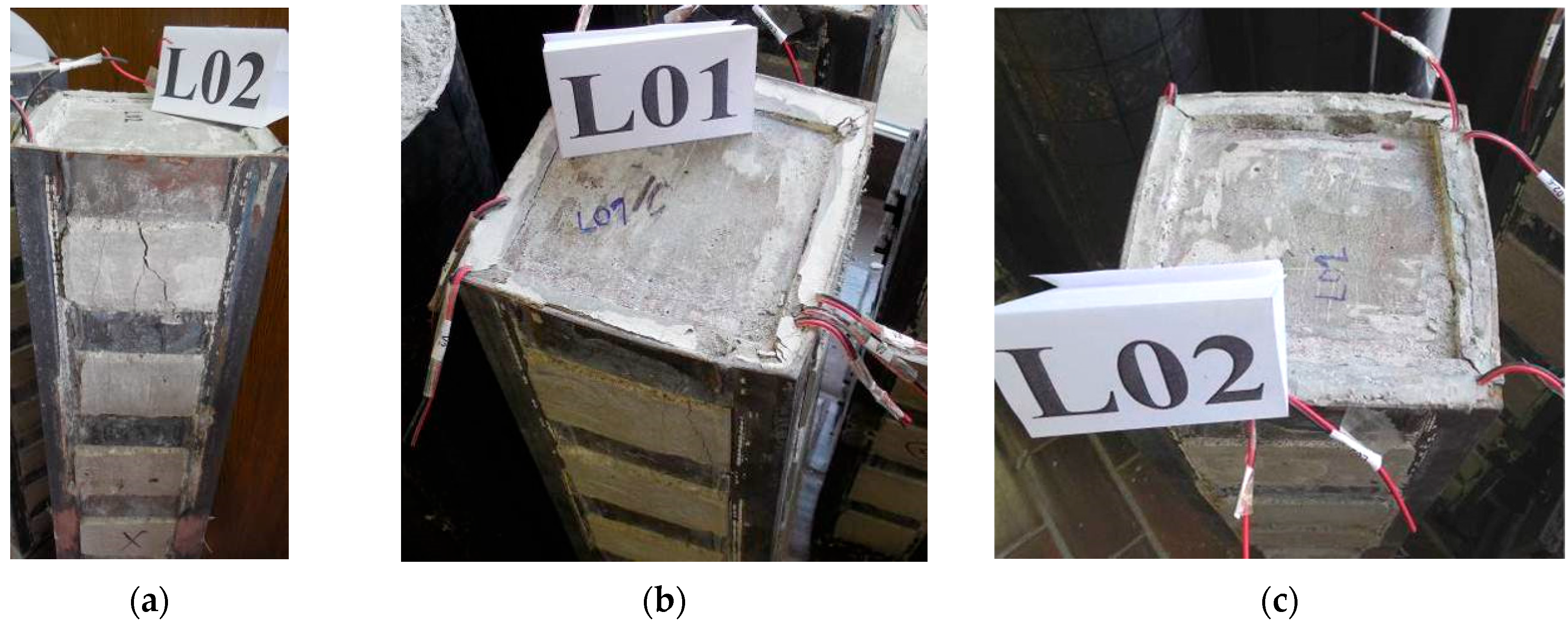
For the L0x group, cracks in all three specimens were observed in the infill concrete at a load of approximately P = 520 kN. The cracks initiated at both ends and progressed upward along the height of the column within the first segment bounded by two horizontal steel plates, at which point failure of the model occurred. The crack width immediately before failure ranged between 0.5 and 0.7 mm. The initiation, location, and development of the longitudinal cracks and fissures were almost identical for all models. As the load increased, the top steel connector plates stretched, affecting the connections between the steel cage, concrete fill, and basic RC column. As a result, the steel cage was unable to effectively restrain the infill concrete, causing the basic RC column to collapse and the load-bearing steel plates to press down into the concrete. Just before failure, indentation of the steel bearing plates into concrete occurred; however, the loss of specimen capacity occurred before the hydraulic press plate came into contact with the steel cage. The local buckling of the angles between battens was not observed.
Figure 16a,b show the top of column model L02 and L01, where the longitudinal cracks in the first segment between the horizontal plates are clearly noticeable. Figure 17b shows the shortening of the original RC column and the formation of an indentation caused by the bearing plate pressing into the surface of the concrete. Transverse cracks formed at the interface between the infill concrete and the basic RC column can also be observed, confirming the conclusion that the bond was compromised and that slip occurred between the components of the composite cross-section. Figure 17c shows the top of column model L02, where the shortening of the original RC column can be seen, similar to the previous specimen. Noticeable bending and stretching of the connecting plates occurred as a consequence of the lateral expansion of the basic RC column and the infill. As with the previous model, transverse cracks around the perimeter at the interface between the two concrete layers are also visible.
All column models strengthened with steel angles and horizontal ties spaced at e = 100 mm exhibited relatively similar failure loads. Ultimate load forces of strengthened columns registered during experimental testing are listed in Table 1, while Table 3 provides the mean value of registered forces, standard deviation of the results (Sn), and coefficient of variation (COV). The standard deviation of the ultimate loads is Sn = 20.0 kN, with a coefficient of variation of COV = 2.2%. Such good agreement between the results indicates uniformity in the quality of the materials used, the fabrication of the models, and the testing procedure itself.
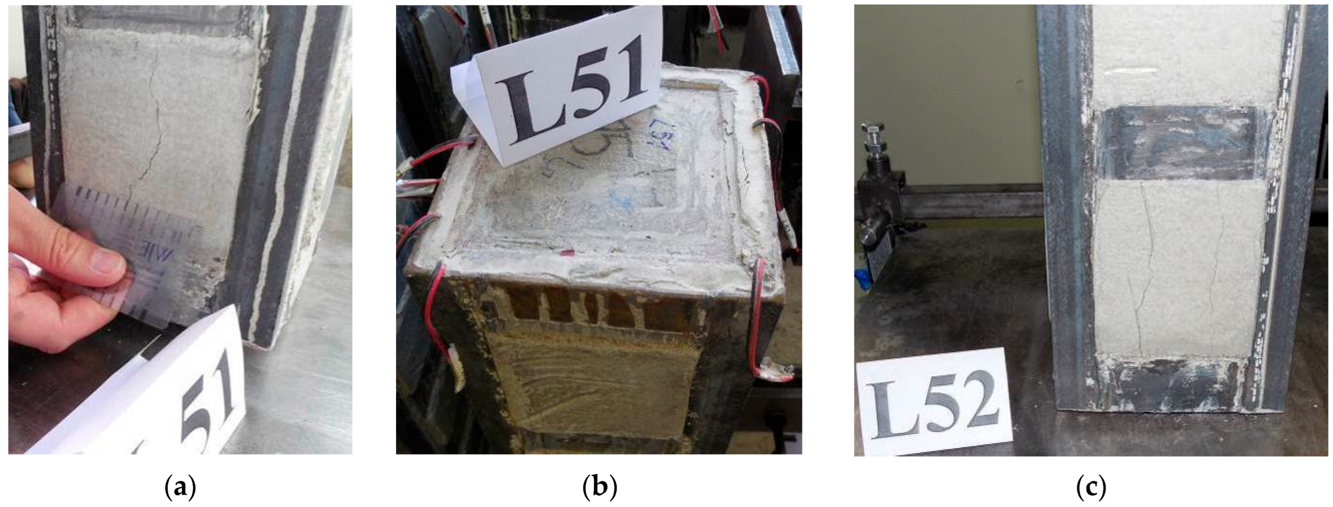
For all specimens of the L5x group, cracks formed in the infill concrete at a load of approximately P = 500 kN. The cracks developed at both ends in the first segment, bounded by the horizontal steel connector plates. The crack width just before failure ranged between 0.7 and 1 mm. The initiation and propagation of longitudinal cracks were almost identical for all models. Similar to the models from the previous group, immediately before failure, the steel loading plates began to indent the concrete surface, but the loss of load-bearing capability occurred before the hydraulic press plate made contact with the steel cage.
Figure 17a,b show the top of specimen L51, where longitudinal cracks can be clearly observed in the first segment between the horizontal steel plates. In Figure 17b, the shortening of the primary RC column is visible, together with the indentation formed by the steel loading plate pressing into the concrete. The same figure also shows cracks that developed at the interface between the infill concrete and the basic RC column, confirming, also for this group, that the bond between the elements of the composite section had been compromised. Figure 17c shows the longitudinal cracks that formed near the bottom of specimen L52, where the cracks extended through the first segment between the steel connector plates.
Table 1 lists the ultimate load forces of strengthened columns measured during experimental testing, whereas Table 3 shows the mean value of recorded forces, standard deviation, and coefficient of variation. The standard deviation of the ultimate loads is Sn = 29.5 kN, with a coefficient of variation of COV = 3.45%. The slightly higher ultimate load observed in column model L52 is likely due to several factors, with the most probable cause being the higher load-bearing capacity of the basic RC column compared to that of the basic RC columns in the other two specimens.
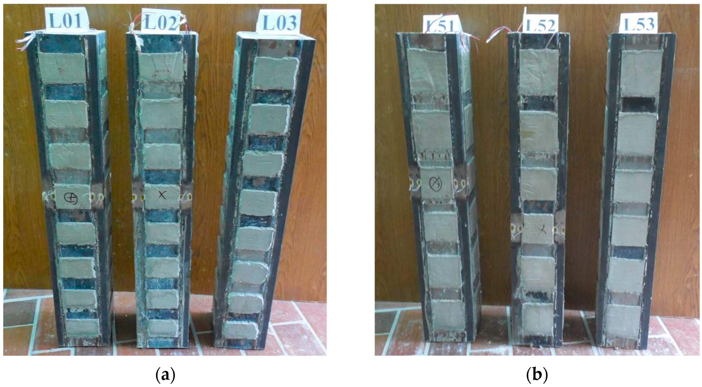
In contrast to the crushing failure of plain RC columns, depicted in Figure 9a–c, the concrete in the basic reinforced columns can maintain its integrity due to the confining pressure imposed by the steel cage. As a result, the strengthened column can retain a significant portion of its load-bearing capacity following the failure of the basic RC column. The steel cage’s confinement to the fill concrete and onto the RC column is reasonably equal throughout the specimen’s height, and the whole portion of the concrete core is well contained. Figure 18a,b, presents all strengthened column models after testing.

4. Analysis of the Test Results

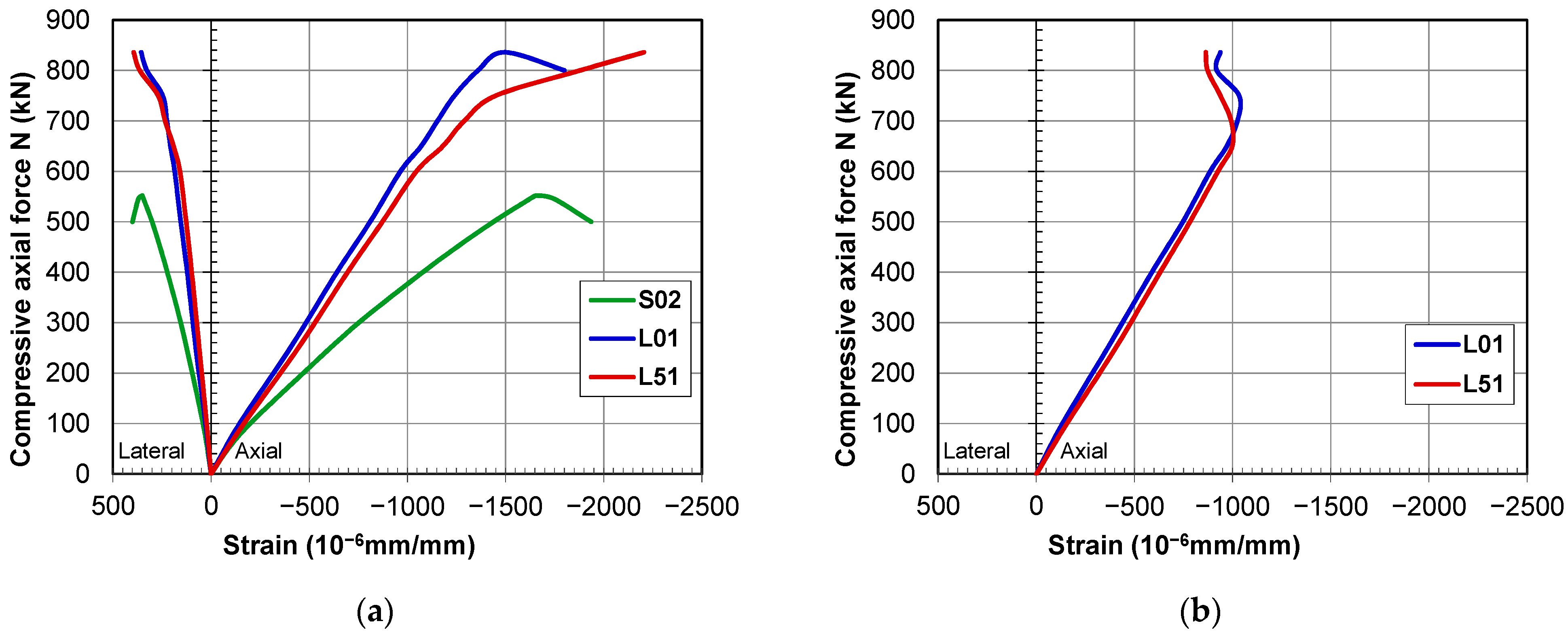
Figure 19a comparatively shows the diagrams of longitudinal and transverse specific strains in the concrete of the basic RC column for representative models from both groups strengthened with steel cages. The diagram also includes the deformations for the plain RC specimen (S02).
For the composite-section models, the longitudinal specific strains in the concrete at the final loading stage (failure) were very similar for specimens in both strengthened groups compared to the control group specimens. The strengthened columns exhibited higher initial stiffness, so for the same values of ultimate strain, they achieved higher load-bearing capacity. Column models with different arrangements of connector plates (L01 and L51) showed almost identical behavior up to 80% of the specimen capacity, i.e., at a load of P = 700 kN. Specimen L01 exhibited slightly stiffer behavior, which resulted in a slightly lower ultimate strain compared to the model from the other strengthened group. The difference between the models is relatively small, so it can be considered that both groups exhibit almost identical behavior with a clearly linear stress–strain response.
When observing the behavior in the service load range, corresponding to a load of up to P = 400 kN, it can be seen that the deviation between the strengthened models is very small, almost negligible. The ratio of the principal strains in the concrete remains constant up to failure.
Figure 19b comparatively shows the diagrams of the axial force versus longitudinal compressive strains in the steel profiles for representative models from both strengthened groups. As in the previous diagram, it can be observed that the deformation behavior of both groups of composite columns is almost identical, and the linear response extends well beyond the service load range. At a load of P = 700 kN, the tensile strain limits in the concrete were reached. Upon reaching the tensile capacity of the infill concrete, longitudinal cracks developed in the SikaGrout (infill). These cracks affected the further transfer of force from the RC column to the infill and the steel profiles. This is also reflected in the specific strain values: in model L01, the strains in the steel increased very little up to failure, whereas in model L51, a small reduction and relaxation of strains in the steel occurred. When comparing the specific strains in the basic RC column with those in the L profiles, it is evident that full composite action and behavior consistent with Bernoulli’s assumption of plane sections remained valid up to 80% of the specimen’s failure load. Beyond this limit, a divergence occurs between the specific strains measured in the RC column and those in the profiles, which is a direct consequence of the cracks and fissures in the infill, leading to deterioration of the composite action of the cross-section components.
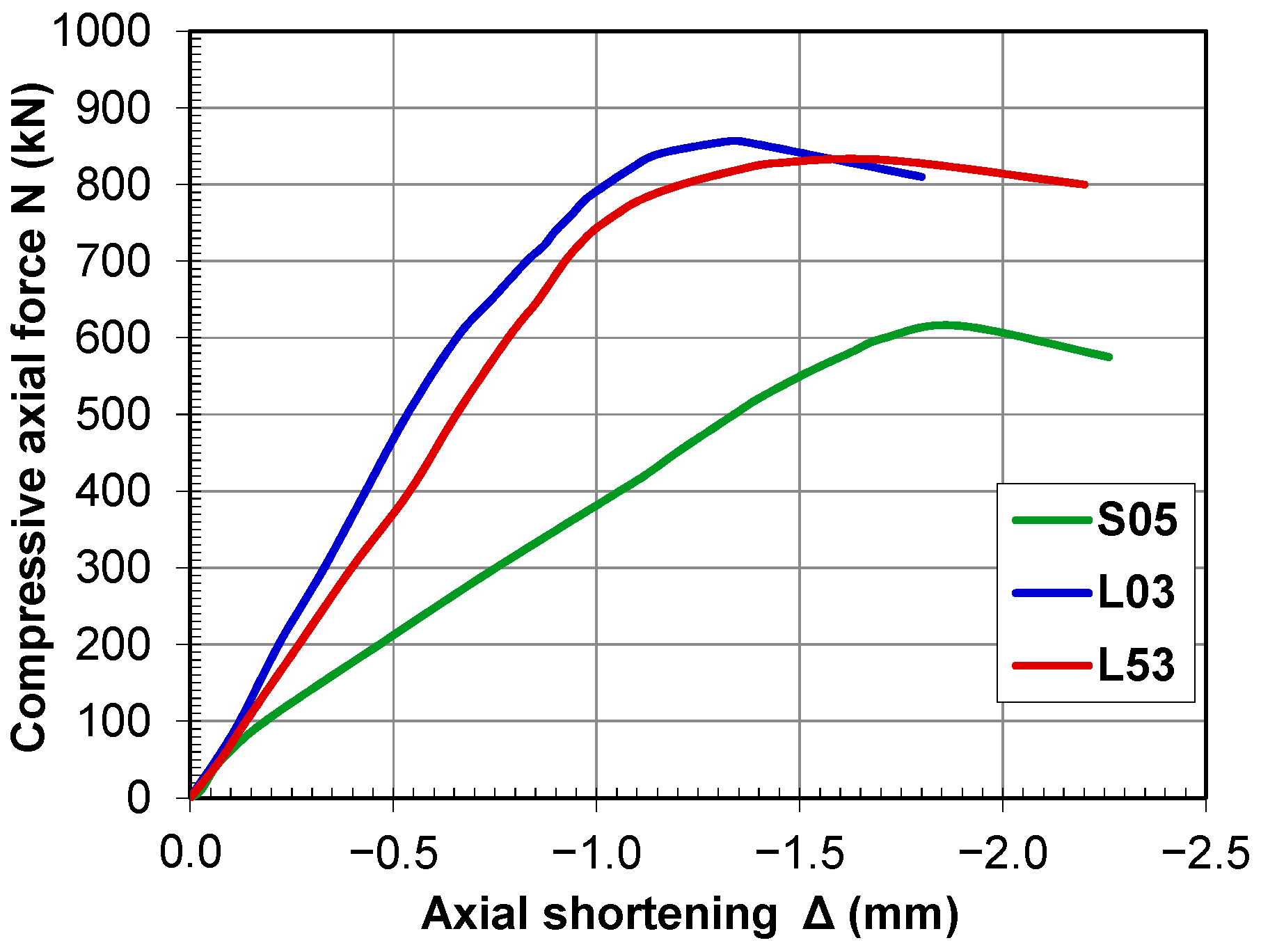
The diagrams in Figure 20 comparatively show the relationship between axial force and longitudinal shortening for the representative column of all three groups. It can be observed that the behavior of all composite-section models is almost completely identical up to failure, and all specimens exhibit a clearly linear response up to a load of 650 to 700 kN. As previously mentioned, at this load, the infill connecting the steel cage and the basic RC column begins to fail, which compromises the composite action of the cross-section. This leads to a significant increase in deformations in the primary RC column and shortly thereafter to specimen failure.
During testing, all six column models with composite cross-sections showed similar behavior. The loss of load-bearing capacity in both groups with composite sections occurs in a similar manner. In the first stage, the tensile strain limits in the RC column, and consequently in the infill, are reached. This is followed by the development of cracks through the infill concrete, which reduces the portion of the load carried by the steel profiles and the infill. As a result, the primary RC column accepts a greater portion of the load. After the infill fails, any further increase in load can only be carried by the primary RC column until its compressive strength is reached. At that point, specimen failure occurs through a combination of concrete crushing and transverse stretching of the connector plates at the column ends. The observed behavior indicates that the bond between the components of the composite cross-section probably failed at the interface of the RC column and the infill. The failure of the interface layer is probably a result of the column model’s characteristic load transfer mechanism. It can be concluded that the ultimate load of the composite-section model is governed by the tensile strains in the infill concrete and the load-bearing capacity of the primary RC column. Although the high compressive strength of the SikaGrout could not be fully utilized, the use of high-quality concrete for the infill is recommended due to the small element dimensions and for the better redistribution of load between the components of the composite section.
Although the experimental program was not specifically designed to evaluate ductility in a quantitative sense, the recorded force–deformation curves and the observed failure modes allow a qualitative assessment of post-peak behavior. Unlike the plain RC specimens, which failed abruptly, the strengthened columns conserved a large part of their load-bearing capability after cracking began, due to the containment provided by the steel cage. This behavior indicates a more stable failure process and higher deformation capacity of strengthened columns. For a deeper assessment of ductility, energy dissipation, and residual capacity, additional cyclic or displacement-controlled testing is needed, which was outside the scope of the presented study.
The cracking and slipping at the interface between two concrete indicate that the post-peak behavior is largely determined by progressive bond deterioration rather than sudden material collapse. The applied strengthening method exhibits quasi-ductile behavior, which is defined by a moderate decrease in stiffness and sustained deformation at constant load. This behavior is important for effective structural retrofitting since it indicates a more predictable and less brittle response of a structure. From a structural safety perspective, the observed post-peak behavior suggests that the proposed strengthening technique enhances not only ultimate capacity but also the robustness of the failure process.
Table 3 shows the mean ultimate load forces for the control group and two groups of strengthened models. In addition to the standard deviation and coefficient of variation of the results, the coefficient of enhanced load-bearing capacity (ks) for a column strengthened using a steel cage is presented.
k s = N u , S C N u , R C
where Nu,SC is the load-bearing capacity of the strengthened column, and Nu,RC is the load-bearing capacity of the plain RC column.
Analysis of the ks values shows that reinforced-concrete columns strengthened with steel angles and SikaGrout infill have approximately 1.45 times higher load-bearing capacity compared to the control group. When comparing the failure loads of the composite columns, it can be observed that the difference is relatively small. The experimentally obtained capacity increase factor is valid for the tested specimens, which can be classified as short columns for which the bearing capacity is governed by material strength rather than stability effects. For slender columns, where second-order effects and global buckling significantly influence structural behavior, the same strengthening efficiency cannot be directly assumed. In slender members, the ultimate capacity is controlled not only by cross-sectional resistance but also by the flexural stiffness of the composite system and by geometric imperfections. Although the steel cage and the concrete infill are expected to increase axial stiffness and delay buckling, the relative contribution of confinement to the overall capacity would likely be reduced compared to compact columns. As a result, the coefficient ks is expected to be lower than the value observed in the presented study. Therefore, the reported strength increase should be interpreted as an upper-bound estimate applicable to short columns under concentric axial loading, and not as a general factor for slender or eccentrically loaded columns.
The experimental results indicate that increasing the batten spacing from 100 mm to 150 mm has a negligible effect on the axial load-bearing capacity of the strengthened columns. Within the investigated spacing range, the steel battens primary role is to ensure geometric integrity of the cage and provide lateral restraint to maintain composite action between the steel angles and the concrete infill. Since the steel angles are continuously supported by the infill concrete along their full height, the confinement mechanism is mainly controlled by the stiffness of the infill layer rather than by the spacing of the batten plates. As long as the battens are spaced appropriately to avoid local separation between steel and concrete, additional spacing decrease has no major effect on confinement efficiency. Consequently, both tested arrangements give a similar amount of restriction, resulting in approximately equivalent load-bearing capabilities. It should be noted that this conclusion applies to the tested geometry, material properties, and loading. For larger columns, weaker infill strength, or increased batten spacing, the impact of connection plate arrangement may become more noticeable, which should be examined in future studies.

5. Theoretical Investigation

5.1. The Design Code Considerations

Numerous authors presented design models for a column strengthened by a steel cage, such as Campione [18], EN 1994-1-1 (EC4) [20], and AISC 360 [31] reported that the axial load capacity Nu of the RC column strengthened with steel is principally calculated from:
N u = N c + N a + N s
where Nc, Na, and Ns represent the contribution of concrete, steel cage, and reinforcement, respectively.
Since the RC column strengthened using the steel cage may be treated as a form of composite steel–concrete element, codes for steel–concrete composite structures are considered in the presented analysis. Additionally, code EN 1988-3 (EC8) [1] is also considered, as it directly takes into account the use of steel angles and battens for enhancing the strength of RC columns. A check if available design codes are suitable for the analysis of RC columns strengthened using a steel cage with an additional concrete layer is presented. The ultimate bearing load is calculated by EC4, AISC 360, and EC8. Since in this research the SikaGrout is used to fill the space between the RC column and steel cage, thus forming an additional layer, the code formulas are expanded to include the use of infill concrete. The contribution of the infill layer (Nf) is added to Equation (2) to form:
N u = N c + N a + N s + N f
The extension of design code formulas to include the contribution of the infill concrete is based on the assumption that the strengthened column behaves as a column with a composite cross-section. This assumption is based on the strain compatibility between the basic RC column, the infill layer, and the steel cage, which is supported by the experimental strain measurements. The infill concrete is confined by the steel cage and is therefore subjected to a triaxial stress state, which is similar to confined concrete in composite columns. The contribution of the infill to the axial capacity of the column can be included in the cross-sectional capacity by extending the effective concrete area in the code formulations.
The EC4 design guide gives the plastic resistance to compression Npl,EC4 of a composite cross-section as the sum of the plastic resistances of its components:
N u , E C 4 = 0.85 ( A c f c k , c ) + A a f y + A s r f s k + 0.85 ( A f f c k , f )
where Ac = 144 cm2, Aa = 7 cm2, Asr = 2.26 cm2, and Af = 63 cm2 are the areas of basic column concrete, steel angles, reinforcement, and fill concrete, respectively, and fck,c, fy, fsd, and fck,f are the characteristic compressive strength of basic column concrete, steel yield strength, yield strength for reinforcement, and compressive strength of fill concrete, respectively. The reduction factor for flexural buckling was 0.998. Since EC4 does not consider the design of composite structures with concrete strength class higher than C60/75, in the presented research, the EC4 approach is extended beyond the concrete strength limits. The effective compressive strength (fc,eff) of SikaGrout is determined as:
f c , e f f = η f c = 1 ( f c 50 ) 200 f c
where the reduction coefficient η is defined in [34]. In that way, the compressive cylinder strength was reduced from fck,f = 63.5 MPa to fck,f = 59.2 MPa.
Code ANSI/AISC 360 gives the compressive strength of compact axially loaded doubly symmetric composite members with a rectangular cross-section, so the axial load-bearing capacity (Nu,AISC) of the CFST member is calculated as a sum of the strength of its individual parts:
N u , A I S C = f y A a + 0.85 f c k , c A c , c + A s r E s E c , c + 0.85 f c k , f A c , f
where Ec,c and Es are the elastic modulus of the concrete and reinforcement, respectively. The reinforcing bars are included in the calculation of the column’s strength as part of the basic RC column. The composite column is considered compact because b / t = 150 / 3 = 50 which is lower than the limit 2.26 E / f y = 62 for non-compact composite columns.
The EC8 design code considers the section’s resistance (Nu,EC8) of a concentrically loaded rectangular RC member with the confinement effects made by steel angles and battens. The load-carrying capacity of the steel angles is excluded from the plastic resistance of the strengthened column. The load-bearing capacity of the confined concrete core, as given by Campione [18], is determined from:
N u , E C 8 = f c d b 2 1 + 2.02 ω s 1 2 3 ( b 2 L 1 ) 2 b 2 1 s 2 b 2 0.87
where the mechanical ratio of steel battens ωs is defined as:
ω s = 4 t 2 . s 2 b s f y d b f c d
In Equations (7) and (8), fcd and fydb are the design strengths of concrete and steel battens, respectively. Additionally, b is the side of a square cross-section, s is the pitch of battens, s2 is the height of a steel batten, L1 is the side length of a steel angle, t1 is the thickness of a steel angle, and t2 is the thickness of a steel batten. The strength of the additional SikaGrout layer is included in the calculation with the equivalent compressive strength determined as:
f c d = A c f c k , c + A f f c k , f A c + A f
with the side length of concrete b = 144 mm.
An additional check using all three codes is performed, assuming Af = 0, hence excluding the SikaGrout fill layer from the load-bearing capacity calculation. In that way, it was possible to assess the impact of the additional layer on the load-bearing capacity of the column.

5.2. Code Result Discussion

The feasibility of using the chosen design codes to estimate the axial bearing capacity (Nu) of an RC column strengthened with a steel cage and infill concrete was investigated for two cases: assuming Af = 0 and Af = 63 cm2.
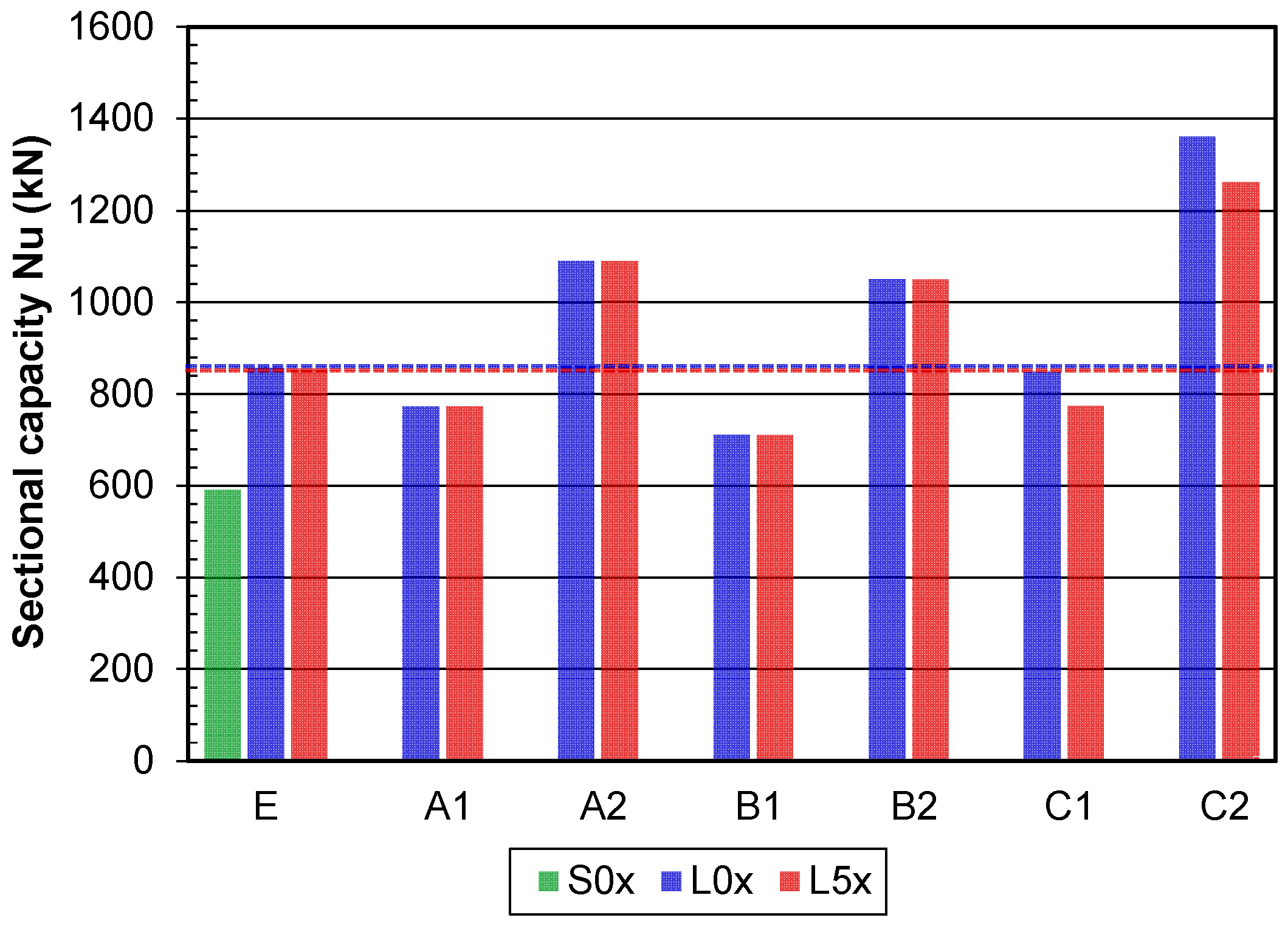
Table 6 and Table 7 show the comparison of the design predictions (Nu,c) and experimental (Nu,e) compressive strengths based on absolute forces and Nu,c/Nu,e ratios. The results in which the fill concrete is not included in the calculation of the bearing capacity are given in Table 6 (Af = 0). Codes EC4 and EC8 gave predictions within 10% of the test value. The mean value of Nu,EC4/Nu,e ratio is 0.90, and for Nu,EC8/Nu,e ratio is 0.95. Code AISC 360 gives conservative predictions with the mean value of Nu,AISC/Nu,e ratio of 0.83. Design codes EC4 and AISC 360 do not differentiate between the two different distances among battens since they assume a continuous steel plate over the entire height of the column. The influence of batten distances is only determined by the EC8 code. For the distances e = 100 mm and e = 150 mm, the ratio Nu,EC8/Nu,e is 0.990 and 0.906, respectively. All three codes gave estimations that are within 10% of the test value, and on the safe side, which leads to the conclusion that the codes are suitable for the calculation of the load-bearing capacity of strengthened RC columns. The results when the strength of the fill concrete is included in the calculated bearing capacity are given in Table 7 (Af = 63 cm2). All three considered codes gave overestimated values, which are between 22% and 59% higher than the experimental values. Based on the given results, it can be concluded that fill concrete does not influence the axial capacity of the strengthened column given by the codes.
The column capacities obtained by the codes and experiments are presented in Figure 21. The experimental values include mean values of the control group column (S0x) and both strengthened groups (L0x and L5x). The dashed lines represent the mean value of the experimental results for the strengthened columns. Column labels are given in Table 6 and Table 7. As can be seen, C1 predictions are closest to the experimental values, followed by A1 and B1. Values A2, B2, and C2 given by the expanded code expressions are over the registered experimental values.
The differences between compared values were anticipated to some degree, mainly because codes take into account composite elements composed of a single type of concrete. Additionally, EC4 and AISC 360 design codes assume that the load acting on a column is transferred through the entire cross-sectional area, but the cage does not provide confinement of the concrete along the full height of the column since the distribution of steel along the column height is discontinuous, which is not accounted for in those codes. The EC8 solutions could be recommended for the design strength calculation.
A good agreement between experimental results and analytical predictions confirms the validity of the approach for the investigated configuration. The proposed extension of the code formulas has limitations since it assumes full composite action and a reliable bond between the infill concrete, the steel cage, and the original RC column. In cases where bond degradation occurs due to interface slip or in cases of poor manufacturing quality, the infill contribution to column strength may be reduced. The formula extension has been validated only for the tested material properties, geometries, and confinement configurations. Its general applicability to different strengthening cases should be treated with caution.

6. Conclusions

This study presents the results of an experimental and theoretical examination into the axial compressive behavior of reinforced concrete columns enhanced with a steel cage and concrete fill. Based on the presented results and within the selected test parameter range, the following conclusions are drawn:
(1) Even if the axial load is only transmitted to the basic RC column, the strain study showed that the steel cage and the infill concrete are engaged for load-carrying. The primary RC column carries 54% of the load, the infill 26%, and the steel cage 20%.
(2) The strengthened column model compared to the plain RC column model demonstrates a higher stiffness and a greater deformation capability. The crushing of the basic RC column concrete, localized outward deformation of the steel plates, and cracking of the fill concrete were the causes of the strengthened columns’ collapse.
(3) The ultimate strength of the strengthened RC columns increased to approximately 1.45 times that of the plain RC column. Increasing the spacing of the steel connector plates from 100 mm to 150 mm had only a minor effect on reducing the column’s load-bearing capacity.
(4) The comparison of results of applied codes shows that Eurocode 4 and Eurocode 8 provide acceptable estimates of the compressive axial strengths of strengthened RC columns, neglecting the infill concrete.
Based on the presented experimental results, the following practical implications and construction guidance for the application of the proposed strengthening method in real structures can be drawn:
(a) The spacing of battens, which is equal to the side length of the cross-section on the compact columns, is sufficient to provide effective composite action.
(b) The compressive strength of the infill concrete should be larger than the compressive strength of the existing concrete.
(c) Surface preparation of the existing column and infill compaction is needed to achieve effective strengthening.
The presented study provides a foundation for understanding the axial performance of columns strengthened with a steel cage and an additional concrete layer. Future studies could investigate the response of strengthened RC columns under the combined influence of axial load and bending, and the performance under cyclic loading. Additionally, parametric studies considering infill thicknesses, material properties, and different steel cage geometries would provide a base for the formulation of practical design-oriented expressions.

Author Contributions

Conceptualization, A.L. and D.K.; methodology, A.L. and D.K.; validation, M.Š. and A.S.-Ć.; formal analysis, A.L.; investigation, A.L. and M.Š.; resources, D.K. and M.Š.; data curation, A.L.; writing—original draft preparation, A.L.; writing—review and editing, A.S.-Ć. and D.K.; visualization, A.L. and M.Š.; supervision, D.K. All authors have read and agreed to the published version of the manuscript.

Funding

The publication of the presented research was supported by the company “Construction Center Ltd.” (Centar za konstrukcije, d.o.o.) from Subotica, Serbia.

Data Availability Statement

The original contributions presented in this study are included in the article. Further inquiries can be directed to the corresponding authors.

Acknowledgments

The authors acknowledge the help from colleagues from the Laboratory for Material Testing at the Faculty of Civil Engineering Subotica.

Conflicts of Interest

The authors declare no conflicts of interest.

References

  1. EN 1998-3:2005; Eurocode 8: Design of Structures for Earthquake Resistance—Part 3: Assessment and Retrofitting of Buildings. European Committee for Standardization: Brussels, Belgium, 2005.
  2. Fib. Model Code for Concrete Structures 2020; International Federation for Structural Concrete: Lausanne, Switzerland, 2023. [Google Scholar]
  3. Campione, G. Strength and ductility of R.C. columns strengthened with steel angles and battens. Constr. Build. Mater. 2012, 35, 800–807. [Google Scholar] [CrossRef]
  4. Khalifa, E.S.; Al-Tersawy, S.H. Experimental and analytical behavior of strengthened reinforced concrete columns with steel angles and strips. Int. J. Adv. Struct. Eng. 2014, 6, 61. [Google Scholar] [CrossRef]
  5. Tarabia, A.M.; Albakry, H.F. Strengthening of RC columns by steel angles and strips. Alex. Eng. J. 2014, 53, 615–626. [Google Scholar] [CrossRef]
  6. Ferrotto, M.F.; Cavaleri, L.; Papia, M. Compressive response of substandard steel-jacketed RC columns strengthened under sustained service loads: From the local to the global behavior. Constr. Build. Mater. 2018, 179, 500–511. [Google Scholar] [CrossRef]
  7. Calderón, P.; Adam, J.M.; Ivorra, S.; Pallarés, F.J.; Giménez, E. Design strength of axially loaded RC columns strengthened by steel caging. Mater. Des. 2009, 30, 4069–4080. [Google Scholar] [CrossRef]
  8. Adam, J.M.; Giménez, E.; Calderón, P.; Pallarés, F.J.; Ivorra, S. Experimental study of beam-column joints in axially loaded RC columns strengthened by steel angles and strips. Steel Compos. Struct. 2008, 8, 329–342. [Google Scholar] [CrossRef]
  9. Johansson, M.; Gylltoft, K. Mechanical Behavior of Circular Steel–Concrete Composite Stub Columns. J. Struct. Eng. 2002, 128, 1073–1081. [Google Scholar] [CrossRef]
  10. Adam, J.M.; Ivorra, S.; Giménez, E.; Moragues, J.J.; Miguel, P.; Calderón, P. Behaviour of axially loaded RC columns strengthened by steel angles and strips. Steel Compos. Struct. 2007, 7, 405–419. [Google Scholar] [CrossRef]
  11. Giménez, E.; Adam, J.M.; Ivorra, S.; Moragues, J.J.; Calderón, P.A. Full-scale testing of axially loaded RC columns strengthened by steel angles and strips. Adv. Struct. Eng. 2009, 12, 169–181. [Google Scholar] [CrossRef]
  12. Garzón-Roca, J.; Adam, J.M.; Calderón, P. Behaviour of RC columns strengthened by steel caging under combined bending and axial loads. Constr. Build. Mater. 2011, 25, 2402–2412. [Google Scholar] [CrossRef]
  13. Garzón-Roca, J.; Ruiz-Pinilla, J.; Adam, J.M.; Calderón, P. An experimental study on steel-caged RC columns subjected to axial force and bending moment. Eng. Struct. 2011, 33, 580–590. [Google Scholar] [CrossRef]
  14. Montuori, R.; Piluso, V. Reinforced concrete columns strengthened with angles and battens subjected to eccentric load. Eng. Struct. 2009, 31, 539–550. [Google Scholar] [CrossRef]
  15. Adam, J.M.; Ivorra, S.; Pallarés, F.J.; Giménez, E.; Calderón, P.A. Axially loaded RC columns strengthened by steel caging. Finite element modelling. Constr. Build. Mater. 2009, 20, 2265–2276. [Google Scholar] [CrossRef]
  16. Giménez, E.; Adam, J.M.; Ivorra, S.; Calderón, P. Influence of strips configuration on the behaviour of axially loaded RC columns strengthened by steel angles and strips. Mater. Des. 2009, 30, 4103–4111. [Google Scholar] [CrossRef]
  17. Badalamenti, V.; Campione, G.; Mangiavillano, M.L. Simplified Model for Compressive Behavior of Concrete Columns Strengthened by Steel Angles and Strips. J. Eng. Mech. 2010, 136, 230–238. [Google Scholar] [CrossRef]
  18. Campione, G. RC Columns Strengthened with Steel Angles and Battens: Experimental Results and Design Procedure. Pract. Period. Struct. Des. Constr. 2013, 18, 1–11. [Google Scholar] [CrossRef]
  19. Sayed, A.M.; Diab, H.M. Modeling of the Axial Load Capacity of RC Columns Strengthened with Steel Jacketing under Preloading Based on FE Simulation. Model. Simul. Eng. 2019, 179, 500–511. [Google Scholar] [CrossRef]
  20. EN 1994-1-1:2004; Eurocode 4: Design of Composite Steel and Concrete Structures Part 1-1: General Rules and Rules for Building. European Committee for Standardization: Brussels, Belgium, 2004.
  21. Adam, J.M.; Ivorra, S.; Pallarés, F.J.; Giménez, E.; Calderón, P.A. Axially loaded RC columns strengthened by steel caging. Proc. Inst. Civ. Eng. Struct. Build. 2009, 162, 199–208. [Google Scholar] [CrossRef]
  22. Zhu, J.; Wen, Z.; Li, Y.; Hou, X.; Lu, Y. Experimental and Numerical Study on Reinforced Concrete Columns Strengthened with Lightweight Alkali-Activated Slag Concrete and X-Type Encased Steel. Buildings 2025, 15, 1692. [Google Scholar] [CrossRef]
  23. Hwanga, Y.-H.; Yang, K.-H.; Mun, J.-H.; Kwon, S.-J. Axial performance of RC columns strengthened with different jacketing methods. Eng. Struct. 2020, 206, 110179. [Google Scholar] [CrossRef]
  24. Cassese, P.; Menna, C.; Occhiuzzi, A.; Asprone, D. Experimental Behavior of Existing RC Columns Strengthened with HPFRC Jacket under Concentric and Eccentric Compressive Load. Buildings 2021, 11, 521. [Google Scholar] [CrossRef]
  25. Shehab, H.; Eisa, A.; Wahba, A.M.; Sabol, P.; Katunský, D. Strengthening of Reinforced Concrete Columns Using Ultra-High Performance Fiber-Reinforced Concrete Jacket. Buildings 2023, 13, 2036. [Google Scholar] [CrossRef]
  26. Lampropoulos, A.; Paschalis, S.; Tsioulou, O.; Dritsos, S. Numerical Investigation of Reinforced Concrete (RC) Columns Strengthened with Ultra-High-Performance Fiber-Reinforced Concrete (UHPFRC) Jackets. Materials 2024, 17, 3380. [Google Scholar] [CrossRef] [PubMed]
  27. Bažant, Z.P. Size effect in blunt fracture: Concrete, rock, metal. J. Eng. Mech. 1984, 110, 518–535. [Google Scholar] [CrossRef]
  28. Carpinteri, A. Decrease of apparent tensile and bending strength with specimen size: Two different explanations based on fracture mechanics. Int. J. Solids Struct. 1989, 25, 407–429. [Google Scholar] [CrossRef]
  29. Bažant, Z.P.; Pfeiffer, P.A. Determination of fracture energy properties from size effect and brittleness number. ACI Mater. J. 1987, 84, 463–480. [Google Scholar]
  30. Taylor, H.P.J. Shear strength of large beams. J. Struct. Div. ASCE 1972, 98, 2473–2489. [Google Scholar] [CrossRef]
  31. ANSI/AISC 360-22; Specification for Structural Steel Buildings. American Institute of Steel Construction: Chicago, IL, USA, 2022.
  32. Landović, A.; Bešević, M. Experimental Research on Reinforced Concrete Columns Strengthened with Steel Jacket and Concrete Infill. Appl. Sci. 2021, 11, 4043. [Google Scholar] [CrossRef]
  33. Han, L.H.; Zhao, X.L.; Tao, Z. Tests and mechanics model of concrete filled SHS stub columns, columns and beam-columns. Steel Compos. Struct. 2001, 1, 51–74. [Google Scholar] [CrossRef]
  34. Chiew, S.P.; Cai, Y.Q. Design of High Strength Steel Reinforced Concrete Columns: A Eurocode 4 Approach; CRC Press: Boca Raton, FL, USA; Taylor & Francis Group: Boca Raton, FL, USA, 2018; ISBN 978-0815384601. [Google Scholar]
Figure 1. Column models: (a) RC column dimensions and reinforcement arrangement; (b) Steel cage dimensions; (c) 3D section of the composite column.
Buildings 16 00882 g001
Figure 2. Strengthening of the columns: (a) Dimensions of the cross-section for the composite column; (b) Steel cages; (c) Pouring fresh concrete in a gap between the steel cage and RC column.
Buildings 16 00882 g002
Figure 3. Testing of concrete properties: (a) Compressive stress–strain curves of column concrete and SikaGrout (SG1); (b) Testing of the elastic modulus on SikaGrout cylinder.
Buildings 16 00882 g003
Figure 4. The test setup schematic and strain gauge positions: (a) RC column; (b) Strengthened RC column; (c) Detail of the strain gauge position on the strengthened RC column.
Buildings 16 00882 g004
Figure 5. Strain gauges and bearing plates: (a) Placement of strain gauges on the steel cage; (b) Protection of the strain gauges on the RC column before strengthening; (c) Load input through the steel plate.
Buildings 16 00882 g005
Figure 6. Column models before the experimental testing: (a) RC column; (b,c) Strengthened columns.
Buildings 16 00882 g006
Figure 7. Plain reinforced concrete specimens (S0x series): (a) Axial load vs. strains diagram; (b) Load vs. deformations diagram.
Buildings 16 00882 g007
Figure 8. The state of longitudinal strains: (a) 3D arrangement of the strains; (b) The centroid stress and strains.
Buildings 16 00882 g008
Figure 9. Failure modes of plain RC columns: (a) The top end of specimen S01; (b) The bottom end of specimen S04; (c) The bottom end of specimen S05.
Buildings 16 00882 g009
Figure 10. Column models after the experiment.
Buildings 16 00882 g010
Figure 11. Strengthened reinforced concrete specimens (L0x series): (a) Axial load vs. strains diagram; (b) Load vs. deformations diagram.
Buildings 16 00882 g011
Figure 12. Strengthened reinforced concrete specimens (L5x series): (a) Axial load vs. strains diagram; (b) Load vs. deformations diagram.
Buildings 16 00882 g012
Figure 13. 3D representation of longitudinal (axial) strains in steel elements: (a) determination of the centroid strains in steel angle L1; (b) The centroid strains in all four angles; (c) The strains in the steel cage.
Buildings 16 00882 g013
Figure 14. Longitudinal (axial) strains in concrete column: (a) 3D arrangement of the strains; (b) The centroid stress and strains.
Buildings 16 00882 g014
Figure 15. Axial strains on the composite column.
Buildings 16 00882 g015
Figure 16. Failure modes of plain L0x columns: (a) Vertical cracks in specimen L02; (b) The top end of specimen L01; (c) The top end of specimen L02.
Buildings 16 00882 g016
Figure 17. Failure modes of plain L0x columns: (a) Vertical cracks in specimen L51; (b) The top end of specimen L51; (c) The top end of specimen L52.
Buildings 16 00882 g017
Figure 18. Strengthened column models after testing: (a) L0x group; (b) L5x group.
Buildings 16 00882 g018
Figure 19. Comparative relationships of the test specimens: (a) Axial force vs. strains in concrete; (b) Axial force vs. strains in steel angles.
Buildings 16 00882 g019
Figure 20. Comparative relationships of compressive axial force vs. axial shortening of specimens.
Buildings 16 00882 g020
Figure 21. Comparison of the calculated and experimental column capacities.
Buildings 16 00882 g021
Table 1. Specimen labels and summary of test information.
No.Specimen
Label
a
(cm)
t
(mm)
L
(cm)
Nu
(kN)
1S0112 90610
2S0212 90558
3S0312 90552
4S0412 90624
5S0512 90616
6L0115390836
7L0215390876
8L0315390856
9L5115390844
10L5215390888
11L5315390832
Table 2. Properties of concrete—mean values.
LabelClassfc (MPa)fcu (MPa)fct (MPa)Ec (GPa)μ (−)ρ (kg/m3)
RC ColumnsC35/4538.650.72.2924.60.162229
SikaGrout (SG1)C60/7563.574.42.2628.50.132295
Note: “fc”, compressive strength of a cylinder; “fcu”, compressive strength of a cube; “fct”, splitting tensile strength of a cube; “Ec”, Young’s modulus, “μ”, Poisson’s ratio; “ρ”, density.
Table 3. Ultimate load forces of column models.
S0xL0xL5x
Nu, exp. (kN)592.0856.0854.7
Sn (kN)36.720.029.5
COV (%)6.22.343.4
ks (−)1.451.45
Note: ks is the coefficient of enhanced load-bearing capacity.
Table 4. Equilibrium of forces for the load P = 400 kN for the L01 specimen.
εi (10−6 mm/mm)Ei (GPa)Ai (cm2)Pi (kN)Pi/Peff (%)
RC column64224.6144227.454.1
SikaGrout infill61528.563110.426.3
Steel angles589200782.519.6
Sum Pi = Peff =420.3100
Note: εSG—strain in SikaGrout infill is the average value of strains in steel and concrete, Peff—effective force in composite column.
Table 5. Equilibrium of forces for the load P = 400 kN for the L51 specimen.
εi (10−6 mm/mm)Ei (GPa)Ai (cm2)Pi (kN)Pi/Peff (%)
RC column69624.6144246.654.3
SikaGrout infill66328.563119.026.2
Steel angles631200788.319.5
Sum Pi = Peff =453.9100
Table 6. Comparison between design predictions and test results—fill concrete neglected.
LabelNu,e (E)Nu,EC4 (A1)Nu,EC4/Nu,eNu,AISC (B1)Nu,AISC/Nu,eNu,EC8 (C1)Nu,EC8/Nu,e
Group L0x856.0773.10.903710.80.830847.60.990
Group L5x854.7773.10.905710.80.832774.10.906
Table 7. Comparison between design predictions and test results—fill concrete included.
LabelNu,e (E)Nu,EC4 (A2)Nu,EC4/Nu,eNu,AISC (B2)Nu,AISC/Nu,eNu,EC8 (C2)Nu,EC8/Nu,e
Group L0x856.01089.51.2731050.91.2281362.51.592
Group L5x854.71089.51.2751050.91.2301260.91.475
Disclaimer/Publisher’s Note: The statements, opinions and data contained in all publications are solely those of the individual author(s) and contributor(s) and not of MDPI and/or the editor(s). MDPI and/or the editor(s) disclaim responsibility for any injury to people or property resulting from any ideas, methods, instructions or products referred to in the content.