1. Introduction
The construction industry is widely recognised as one of the primary contributors to environmental degradation at a global scale. Within the European Union (EU), the built environment sector accounts for approximately 40% of total greenhouse gas emissions and generates nearly one-third of all waste produced, with only around 40% of construction and demolition waste (CDW) undergoing recycling or reuse during building demolition operations [
1]. In terms of absolute mass, CDW represents the largest waste stream in the EU, amounting to approximately 374 million tonnes in the EU-28 in 2016, with figures remaining broadly stable in subsequent years [
2]. As shown in Iacovidou & Purnell [
3], although recovery rates appear elevated on an aggregate scale, the vast majority of CDW recovery is in fact achieved through low-grade operations such as backfilling and the use of recycled aggregates in road sub-bases, which correspond to only modest levels of material circularity. In [
3], the excellent reuse potential (>50%) of structural steel components is highlighted, classifying such material as one with the highest reuse potential across all construction sectors; for instance, the reuse of steel and glass components can save more than 60% of the carbon associated with their recycling.
Exploiting the full environmental potential of CDW management—estimated by the European Commission Joint Research Centre as approximately 33 Mtons of CO
2-equivalent saving per year—requires a paradigm shift, i.e., from material recycling towards the direct reuse of structural components [
4].
To this end, the circular economy has emerged as the overarching strategic framework for the transition towards a sustainable construction sector. The European Green Deal, made operational through the Circular Economy Action Plan, has identified the built environment as one of the priority sectors for achieving climate neutrality by 2050 [
5]. Within this paradigm, the concept of design for deconstruction (DfD)—also referred to as design for disassembly—has been progressively established as the foundational design philosophy enabling the disassembly, recovery and redeployment of structural elements at the end of their service life in a given application [
6]. The underlying principle is clear: for structures to be genuinely demountable and reconfigurable, the DfD philosophy must be embedded from the earliest stages of the design process, with the type of connections adopted playing a decisive role in this regard, especially for steel and timber structures [
7].
In Europe, despite the acknowledged environmental advantages of direct reuse, currently only 11% of structural steel is directly reused, whilst 88% is recycled [
8], a disparity that the construction industry shall urgently address if it is to meet its climate commitments within the timeframe set by European policy.
In this framework, structural steel possesses a distinctive combination of material characteristics that render it particularly well-suited to direct structural reuse. Its inherent properties—high strength-to-weight ratio, material homogeneity and isotropy, ductility, weldability and workability—allow the structural performance of recovered elements to be basically unaltered over multiple service lives, provided that appropriate service and storage conditions are observed. Unlike reinforced concrete—in which the separation of steel reinforcements from the concrete matrix is technologically challenging and economically prohibitive—hot-rolled steel profiles can be dismantled and redeployed whilst retaining their full cross-sectional geometry and original mechanical properties [
3]. Demountable and reconfigurable steel structures capable of repeated reuse without the loss of structural performance have been shown to reduce environmental impacts and advance circular economy principles, constituting an attractive option for modern facilities subject to frequent modifications [
9].
In Kanylmaz et al. [
10], quantitative evidence of these long-term environmental benefits is provided via a multi-objective sensitivity study across 36 building configurations with variable geometries, material types and floor systems. Results highlighted how structures employing reused steel sections exhibited the lowest embodied carbon levels among all material options assessed—i.e., approximately 43% lower than those obtained using typical structural steel, 14% lower than recycled steel, and 25% lower than sustainably sourced mass timber with carbon sequestration [
10].
At the component level, the first available Environmental Product Declaration for reused structural steel reports a global warming potential of approximately 50 kgCO
2eq/ton of steel for life-cycle stages A1–A3 (material supply to manufacturing [
11]), representing a potential reduction of up to 95% compared to primary steel production via basic oxygen furnace processes [
12]. Life-cycle assessment (LCA) studies on beam-to-column joints incorporating DfD connections have further confirmed that, whilst embodied carbon may increase during the construction phase relative to conventional solutions, the total carbon emissions over the entire service life of the structure are significantly reduced when reuse is accounted for [
13]. These findings are consistent with the position of the international steel industry, which recognises that modular design using steel construction methods and demountable connections allows buildings to be repurposed rapidly and cost-effectively without the need for remanufacturing [
14].
A successful, pioneering demonstration of this approach is indeed represented by the BedZED zero-energy development in South London, in which 98 tonnes of reclaimed structural steel—i.e., 95% of the used structural steel—were successfully incorporated, with a cost ≈4% below that of equivalent new sections and an estimated saving of 21 tonnes of CO
2 [
15].
The institutional recognition of structural steel reuse as a viable and desirable engineering strategy has been formalised at the European level through the publication of CEN/TS 1090-201:2024: Execution of Steel Structures and Aluminium Structures—Reuse of Structural Steel [
16]. This technical specification provides complementary provisions to EN 1090-2 [
17] for the use of reclaimed structural components in the execution of steel structures with execution classes EXC1, EXC2, and EXC3. CEN/TS 1090-201:2024 specifies requirements for the reusability assessment of reclaimed structural components, including the declaration of mechanical and geometrical properties as well as their weldability, and applies to hot-rolled profiles and hot-finished or cold-formed hollow sections used as constituent products in accordance with EN 1090-2.
In line with the purposes of the present work, it is worth highlighting that CEN/TS 1090-201:2024 provisions currently only apply to structures designed according to EN 1993-1-1 [
18], that is, without seismic and/or fatigue design, although national standards retain the discretion to add non-contradictory requirements with regard to seismic loading [
16]. This normative boundary implies that, under the European regulatory framework in force, the direct reuse of reclaimed structural steel components is formally permitted for gravity-load-resisting (GLR) members—that is, those not assigned to the seismic-load-resisting (SLR) system—thereby delineating a specific and practically relevant scope of application for the development of demountable connection solutions for GLR frames of steel-framed structures. This regulatory evolution is further supported by the EU Taxonomy for Sustainable Finance, which requires that at least 70% of the total metallic material in new buildings originate from secondary sources, reinforcing the urgency of developing practical frameworks for structural steel reuse [
12].
Whilst the material properties of structural steel are inherently conducive to reuse, the practical realisation of demountable structures critically depends on the type of connection adopted. Conventional joining methods—e.g., welding and “standard” bolting—present fundamental limitations in a reuse-oriented perspective. Welding, despite offering high stiffness and load-carrying capacity, introduces residual thermal deformations and localised micro-structural modifications to the base metal, rendering the connection irreversible in practice and compromising the integrity of the element for subsequent service lives. On the other hand, standard bolting—whilst reversible in principle—requires pre-drilling of the cross-section, which (i) reduces the net-area of the member, (ii) introduces local stress concentrations, and (iii) permanently alters the geometry of an element intended for reuse.
A systematic review by Bartsch [
8], encompassing 130+ publications, confirmed that the absence of demountable connection solutions is one of the main technical barriers impeding the widespread diffusion of structural steel reuse in Europe, i.e., due to existing connections being frequently monolithic—welded or cast; this prevents non-destructive disassembly and precludes subsequent reuse of the members. Alongside this technical barrier, the same review identified the lack of adequate design rules and standards as one of five key challenges facing the field, a finding corroborated by Kanyilmaz et al. [
12], who further highlighted that the reuse practice was slowly proceeding precisely because designers, contractors and property owners lacked sufficient guidance and rules for planning and executing reuse projects.
DfD guidelines therefore recommend explicitly minimising the use of fixings to structural steel elements that require welding or the drilling of holes and instead, advocate the use of clamped fittings wherever possible [
19]. Clamp-based systems achieve fully reversible connections without altering the geometry or integrity of the structural element: this connection type is particularly well-suited to applications where it is necessary to rehabilitate or modify existing steel structures by attaching new profiles without the need to drill or weld the original member [
20]. From an operational standpoint, clamping avoids time-consuming site welding, eliminates the requirement for hot-work permits, and enables straightforward positional adjustment without the need to introduce additional holes.
Research on clamp-based connection systems for demountable steel structures has grown steadily over the past decade, stimulated by the progressive consolidation of the DfD paradigm. A systematic state-of-the-art review by Cabaleiro et al. [
7] demonstrated that clamp-based systems represented the optimal solution for entirely demountable structures, as they permitted fully reconfigurable configurations—with the sole operation of cutting the profile to size—and accommodated a wide variety of connection arrangements. Subsequent experimental and numerical investigations have examined the structural performance of clamp-based joints in a range of configurations. Cabaleiro et al. [
21] conducted experimental tests on beam-to-column connections using triangular clamp-based fastening systems of two sizes (180 mm and 260 mm), applying controlled bolt pre-tension and progressive vertical loading whilst continuously monitoring displacements and forces. Relevant numerical simulations confirmed that all configurations remained within the elastic domain, and that clamp-based joints maintained a uniform stress distribution across the clamping surface under monotonic loading, thereby preserving elastic behaviour and enabling component reuse.
In a first attempt to overcome CEN/TS 1090-201:2024 applicability limitations, the fatigue behaviour of clamp-based connections has also received recent attention: Cabaleiro et al. [
20] identified a significant gap in the literature regarding the response of such joints under dynamic loading as a function of the geometric characteristics of the clamp levers.
From a sustainability perspective, quantitative LCA and life-cycle cost (LCC) evidences confirmed that demountable and reconfigurable steel structures with clamp-based connections possessed the capacity for repeated reuse without the loss of structural performance over multiple service cycles [
9].
Notwithstanding the ongoing research on clamp-based systems and demountable connections, a specific and significant gap persists in the technical literature. Indeed, whilst research on clamp-based and bolted-pinned beam-to-column connections are currently emerging, dedicated studies on demountable shear beam-to-column connections specifically designed for the gravity frame of steel-framed structures are still absent in the literature. Existing contributions focus predominantly on steel–concrete composite systems (e.g., shear connectors for bridge girders, seismic joints for composite frames [
22,
23,
24]), clamp-based joints for light industrial platforms [
7], or moment-resisting connections for seismic frames [
25].
Fully demountable simple shear connections—specifically conceived for GLR beams in steel-framed buildings and designed to avoid any welding or drilling of the members intended for reuse—remain essentially unexplored from the perspectives of structural design, finite-element modelling, and systematic comparison with conventional solutions. This gap is of key practical relevance in light of (i) the mentioned limitations on reusable members as per CEN/TS 1090-201:2024 [
16] and (ii) requirements from the EU Taxonomy to have at least 70% secondary metallic material in new buildings [
12]—especially if one considers that direct reuse of structural steel can reduce embodied carbon by up to 95% compared to primary production [
10].
The present paper aims at addressing such a gap by proposing a design approach, the finite-element modelling and the performance evaluation of demountable friction-type beam-to-column shear connections. Accordingly, the work is mainly divided into three parts. In
Section 2, the design procedure for the proposed demountable connections is described in detail. Subsequently, the main assumptions and the extent of the parametric numerical study—i.e., performed to provide a first validation of such procedure—are presented in
Section 3. Finally,
Section 4 summarises the main results from FE analyses, providing useful insights about parameters governing the performance of the investigated demountable joints.
2. Design Procedure
2.1. Conceptual and Typological Definition of the Connection
The connection investigated in the present study is a demountable beam-to-column shear connection conceived in accordance with the principles of DfD. The proposed solution is based on a friction-type load-transfer mechanism achieved through clamp-based components, thereby avoiding any form of permanent modification to the structural members intended for reuse.
The proposed beam-to-column shear connection is conceived as a fully demountable clamped joint system specifically developed to avoid any drilling or permanent modification of the primary steel members. The connection relies on a combination of internal clamping inserts, external clamping plates, and high-strength bolted assemblies that, together, provide the transfer of shear forces between the connected members while preserving the integrity and reusability of the steel profiles.
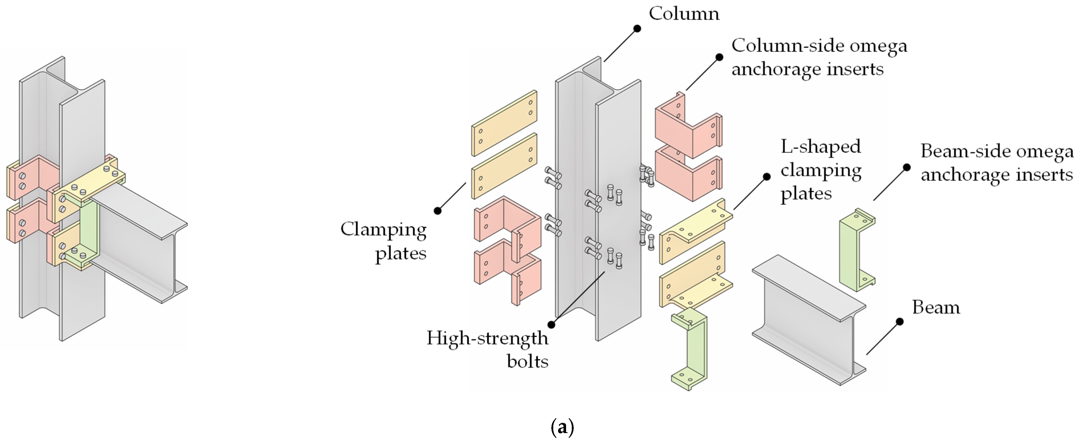
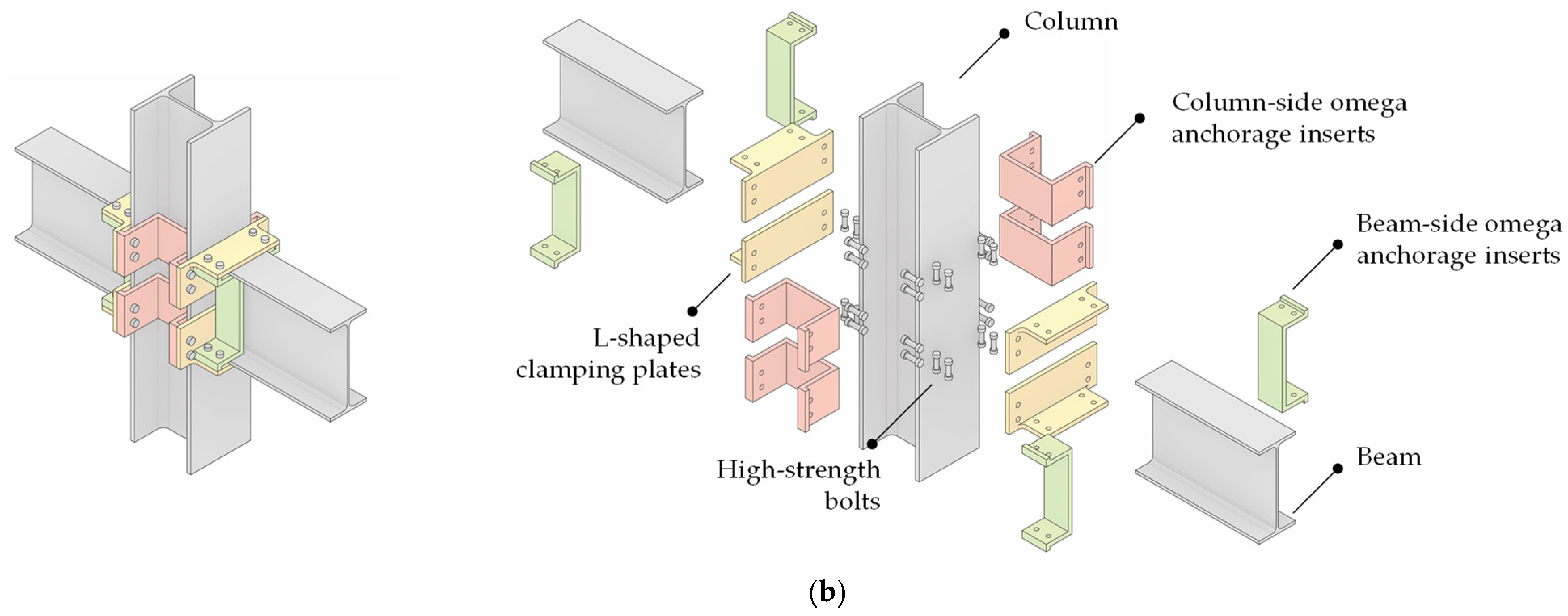
The joint configuration is composed of four principal components (see
Figure 1):
- (i)
internal omega-shaped anchorage inserts;
- (ii)
external L-shaped clamping plates;
- (iii)
high-strength bolted fasteners;
- (iv)
connected steel beam(s) and column.
The primary steel members consist of standard rolled I-sections arranged in an orthogonal beam-to-column configuration. The column remains continuous through the joint region, while the beam frames into the column-flange intersection without requiring welded attachments or drilled bolt holes in either member. Such a solution is particularly suitable for structures designed according to circular economy principles, where reversibility, adaptability, and component reuse are of primary importance.
The
beam-side omega anchorage inserts (see
Figure 1, green elements) and the
column-side omega anchorage inserts (see
Figure 1, red elements) are Ω-shaped steel profiles specifically designed to fit inside the open regions of hot-rolled steel members. Their geometry and positioning near beam/column flanges enable them to act as internal reaction devices for the clamping system. Due to their folded geometry, these inserts exhibit enhanced local stiffness while maintaining relatively low material consumption. Moreover, the omega configuration facilitates stable positioning within the steel sections and improves resistance against local deformation induced by bolt preloading.
The
external L-shaped clamping plates or
angle clamping brackets (see
Figure 1, yellow elements) constitute the external load-transfer mechanism of the connection. Each component is fabricated from bent steel plates forming an L-shaped cross-section, with the two orthogonal legs arranged to be respectively in contact with the beam and the column surface. Their geometry enables simultaneous engagement of both connected members, thereby creating an efficient force-transfer path between beam and column.
The horizontal leg of each clamping bracket bears against the beam-flange region, while the vertical leg bears against the column-flange region. The arrangement generates a three-dimensional confinement effect around the joint zone. In addition, the use of paired clamping brackets on opposite sides of the connection ensures a balanced distribution of forces and reduces eccentricities within the load-transfer mechanism.
The force transfer between the external clamping plates and the internal omega inserts is achieved through high-strength bolts passing through the clamping assembly. Importantly, fasteners do not penetrate the primary structural members themselves. Instead, they only connect external L-shaped clamping brackets and internal omega anchorage inserts. Upon tightening, the bolts generate a clamping force that compresses the beam and column surfaces between the internal and external steel components. The resulting frictional resistance and bearing interaction allow the transfer of shear forces across the connection without requiring any perforation of the connected members.
This solution offers several structural and practical advantages. First, the absence of drilling operations eliminates stress concentrations and avoids weakening of the parent steel sections. Second, the fully bolted and detachable nature of the assembly facilitates rapid erection and dismantling procedures. Third, all hot-rolled members can potentially be recovered and reused at the end of the structure’s service life, thus enhancing sustainability and reducing construction waste.
From a mechanical perspective, the connection behaves as a friction-based clamped shear joint. The preload introduced in the bolts generates contact pressures between the external clamping plates and the steel members, while the omega inserts provide the internal reaction necessary to stabilise the assembly. Depending on the adopted bolt preloading level and surface treatment conditions, the connection may develop significant slip resistance prior to the activation of bearing mechanisms.
Furthermore, the modular nature of the system allows straightforward scalability and adaptation to different beam and column sizes. The geometry and thickness of both the omega anchorage inserts and the L-shaped clamping brackets may be tailored according to the required resistance, stiffness, and assembly constraints. Additional rows of bolts or supplementary clamping modules may also be introduced to enhance the load-carrying capacity of the joint.
From a practical perspective, the installation of the proposed connection requires adequate access around the joint for positioning the clamping components and tightening the preloaded bolts. This may influence the detailing of adjacent secondary beams, floor decking and other non-structural components, which should not interfere with the clamping assembly or hinder inspection and dismantling. Attention should also be given to controlling the beam-to-column clearance gap during fabrication and erection, since excessive deviations may affect the rotational capacity and force-transfer mechanism of the joint. Temporary positioning devices or calibrated spacers may therefore be required. Finally, bolt tightening should follow controlled procedures, and the achieved preload should be verified using standard inspection methods for preloaded bolted assemblies.
2.2. Design of the Clamped Connection
The design procedure adopted for the proposed demountable clamped beam-to-column joint is based on (i) resistance models for slip-resistant preloaded bolted connections [
26], (ii) the principles of capacity design [
27], and (iii) the local equilibrium of the clamping components. In addition, serviceability and reusability considerations are implemented at the member and connection scale to ensure complete reversibility of the structural system while avoiding any drilling or welding operations on the primary steel members.
The preliminary stage of the design process consists of the selection of the beam and column cross-sections according to ultimate limit state (ULS) combinations as per EN 1991-1 [
28]. As opposed to conventional steel design approaches—in which attaining the plastic resistance of members is generally accepted—the DfD philosophy intentionally limits stress levels within the elastic range, i.e., in order to preserve the integrity and future reusability of the structural members. Accordingly, beams and columns are designed by satisfying the following conditions (Equation (1)):
where X
el,Rd and X
Ed (X = M, N, V) represent the design, elastic cross-section capacity and the relevant design demand, respectively.
Once beam and column profiles have been selected, the design shear force acting on the beam-to-column connection is determined according to a local hierarchy criterion [
26]. Since the structural arrangement corresponds to a simply supported beam scheme, the maximum bending moment develops at mid-span, whereas the maximum shear force is transferred at the beam ends. In order to ensure an adequate hierarchy between member resistance and connection resistance, the beam-end shear force is evaluated assuming the formation of a plastic hinge in the most stressed section, i.e., at mid-span. Under this assumption, the design shear force V
Ed,j transmitted by the connection may be evaluated through equilibrium considerations (Equation (2)):
where M
pl,Rd,beam is the plastic bending resistance of a beam spanning L
b and α is a load-distribution coefficient (e.g., α = 4 for uniformly distributed loads or α = 2 for a single mid-span applied force).
This approach ensures that the connection possesses sufficient overstrength with respect to the beam response and prevents premature slippage of the clamped joints.
A fundamental aspect in the design of clamped joints is the definition of the internal lever arms governing the transfer of forces within the clamping assembly. Unlike conventional slip-resistant lap joints, the proposed connection does not consist of fully contacting plates, but rather of external L-shaped clamping brackets interacting with internal omega anchorage inserts. Consequently, the load-transfer mechanism is strongly influenced by the eccentricity of the clamping forces.
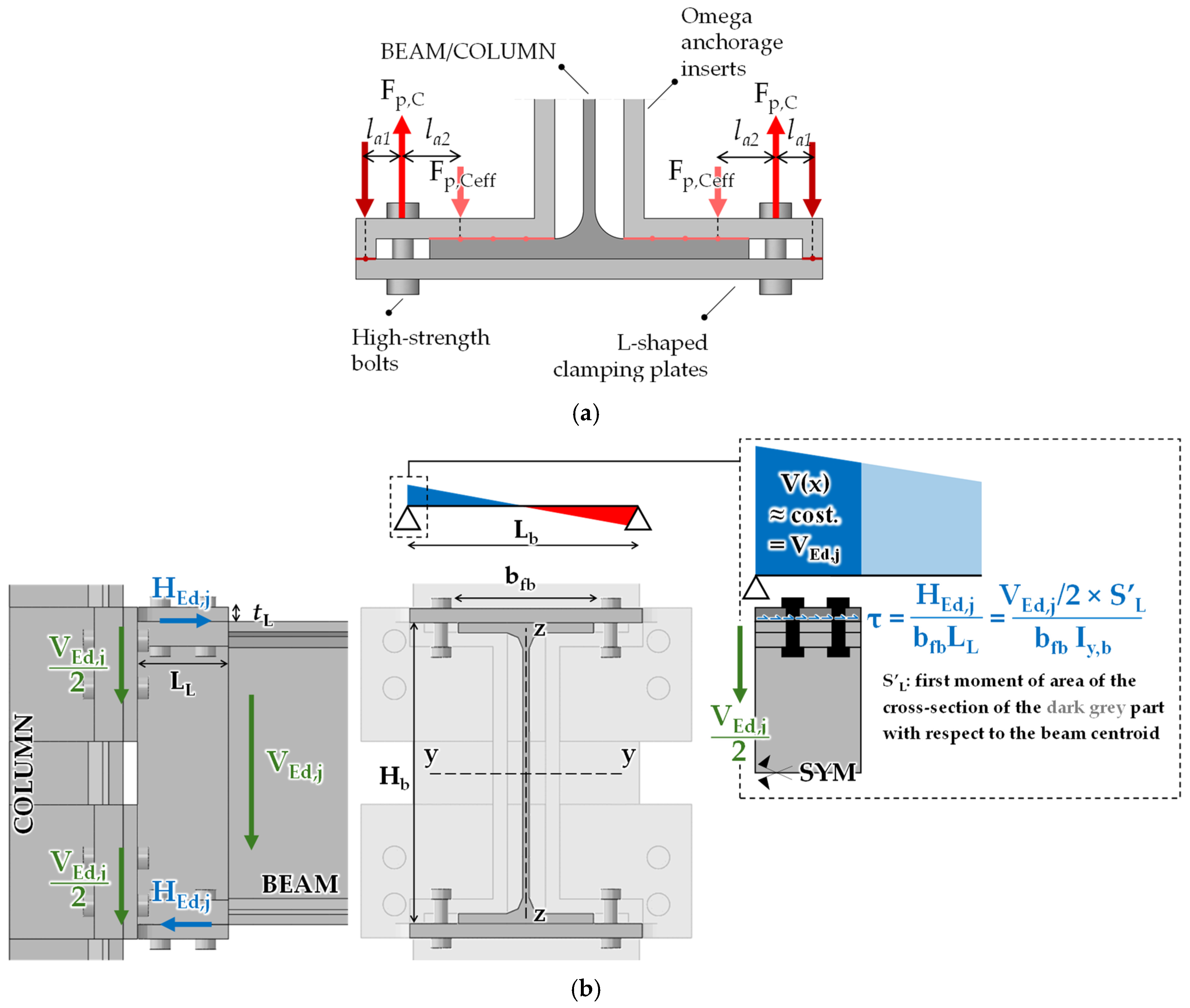
Two distinct lever arms may therefore be identified (see
Figure 2a):
the external lever arm , defined as the distance between the bolt axis and the contact interface between the L-shaped clamping bracket and the omega anchorage insert;
the internal lever arm, defined as the distance between the bolt axis and the resultant compressive contact force transmitted to the column flange.
The interaction between these two lever arms affects the effective slip resistance of the joint, i.e., as confirmed by experimental and analytical investigations available in the literature [
21].
Namely, the effective clamping force F
p,C,eff decreases as the eccentricity ratio between the two lever arms increases. To account for this phenomenon, a reduction coefficient β may be introduced (Equation (3)):
so that the effective clamping force acting within the connection becomes (Equation (4)):
where
is the nominal bolt preload force.
The design slip resistance of a preloaded bolt is then evaluated according to EN 1993-1-8 provisions (Equation (5) [
26]):
where
is the hole factor;
is the number of slip planes;
is the slip factor (friction coefficient);
is the bolt preload force;
is the partial safety factor for slip resistance.
For the proposed clamped configuration, the effective slip resistance is therefore reduced as (Equation (6)):
The coefficient hence explicitly accounts for the non-uniform force transmission mechanism typical of clamped assemblies.
From a geometrical perspective, efficient clamped joints are obtained when the bolts are positioned as close as possible to the column surface (
→ 0). Such a configuration indeed maximises the effectiveness of the preload transfer and reduces secondary bending effects within the clamping brackets. Conversely, the distance
can be generally reduced up to the minimum edge distance
e2,min as per EN 1993-1-8 [
26]. This approach allows the overall transverse dimension of the connection to be limited while maintaining adequate bearing resistance and constructability.
The required number of preloaded bolts on the column-side
nb,c may then be directly obtained by comparing the design action to the effective slip resistance capacity (Equation (7)—see
Figure 2b):
Concerning the sizing of both the omega anchorage inserts and the external L-shaped clamping brackets, their thickness and should be such as to ensure adequate out-of-plane stiffness of the clamping components. In particular, a sufficient thickness is required to prevent significant bending deformations and potential instability phenomena of the plates. Otherwise, local loss of contact pressure at the faying interfaces may occur due to plates opening, with a consequent reduction in the slip resistance of the connection.
On the beam side, the same geometrical and mechanical principles are adopted. In this case, the bolts are primarily subjected to horizontal slip forces H
Ed,j; they can be approximately estimated via a Jourawsky-like expression based on treating the Beam+L-brackets subset as a composite element with partially prevented slippage between the parts (see
Figure 2b). The resulting expression ensures equilibrium with vertical shear on the column side and local axial forces on the beam flanges (Equation (8)):
where
Hb, bfb, and Iy,b are the beam depth, flange width and strong-axis second moment of the area;
LL and tL are the L-shaped clamping plate length and thickness.
As anticipated, the connection is intended to behave as a nominally pinned shear joint. Therefore, the beam-side clamping system must satisfy two requirements: (i) its slip resistance must be larger than the horizontal force HEd,j required to ensure equilibrium of the clamping mechanism, while (ii) should be sufficiently limited to avoid undesired transmission of a significant bending moment.
According to the resistance classification framework of EN1993-1-8 [
26], a joint may be classified as nominally pinned when its design moment resistance M
j,Rd does not exceed 0.25 M
pl,Rd,beam—provided that an adequate rotation capacity is available.
In the present case, the maximum moment transmitted by the beam-side clamping mechanism before slip may be conservatively estimated as per Equation (9):
where
is the vertical lever arm between the upper and lower beam-side clamping interfaces. Assuming
, resistance boundaries for the beam-side connections can be finally written as follows (Equation (10)):
It is worth emphasising that the above conditions—while preserving a simple and practice-oriented form—only ensure the fulfilment of Eurocode 3 resistance requirements for pinned connections, while no insights are provided in terms of bending stiffness. Defining a design criterion in this regard would require the use of more complex analytical approaches, which are beyond the scope of this preliminary study—e.g., a dedicated application of the component method [
26].
Nevertheless, the adopted connection configuration—which does not involve components extending beyond the beam’s footprint—is still expected to only provide moderate bending stiffness, due to its typological similarity to flush-end plate connections commonly adopted for pinned joints [
29,
30]. The validity of this assumption is extensively assessed in the following sections based on results from refined numerical simulations.
3. Extent of the Parametric Analyses and Relevant Assumptions
3.1. Case Study Selection and Design of Members
The structural performance of the proposed demountable clamped shear connection was investigated through an extensive finite-element parametric study carried out on four beam-to-column joint configurations representative of typical steel-framed buildings. Particular attention was devoted to interior beam-to-column joints, since these configurations were typically characterised by higher shear demands with respect to edge joints, i.e., due to the contribution of beams framing into both sides of the column.
The selected case studies were defined in order to cover the typical application range of multi-storey residential and office steel buildings [
30,
31]. In these structural systems, gravity loads are mainly carried by secondary beams supporting the composite floor slab, while the secondary beams, in turn, transfer their reactions onto the main beams connected to the columns. For conventional hot-rolled steel floor systems, the span of the primary beams typically ranges up to approximately 9 m. Consequently, four representative beam spans were considered within the parametric investigation [4.5 m, 6.0 m, 7.5 m, 9.0 m].
Main beams were modelled as simply supported members subjected to a combination of distributed and concentrated gravity loads. The distributed load accounts for the self-weight of the structural and non-structural components, as well as façade loads in the case of perimeter beams. In addition, concentrated forces were introduced at the locations corresponding to the secondary beam connections.
The number of secondary beams was selected consistently with the typical span range of composite floors made of profiled steel decking and reinforced concrete topping [≈2–3 m]. Accordingly, the considered structural layouts included:
two secondary beams for main beam spans Lb = 4.5 m, 6.0 m;
three secondary beams for Lb = 7.5 m;
four secondary beams for Lb = 9.0 m.
This assumption directly affects the shear force transferred to the beam-to-column connection, due to relevant modifications of the internal force distribution along the main beam (see Equation (2)).
In accordance with the design methodology described in
Section 2.2, the design shear force transferred by the connection was evaluated through a local hierarchy criterion based on the development of the beam plastic resistance at mid-span. For the configurations with two secondary beams, concentrated forces due to load transfer were assumed as located at approximately L
b/3 and 2L
b/3. This results in a load-distribution coefficient α = 3. The same value is achieved for the 7.5 span configuration involving three equally spaced forces (
i = L
b/4), while α = 10/3 is obtained for the longest span configuration subjected to four concentrated loads.
With regard to main beams’ cross-sections, profiles were selected to fulfil ULS and serviceability requirements as per EN1993-1-1 [
18] under typical gravity loads for a steel-framed building with composite deck (
gk ≈ 4.5 kN/m
2,
qk = 2.0–3.0 kN/m
2). Accordingly, the span-to-depth ratios reported in Di Lorenzo et al. [
32]—derived via an extensive parametric study—were used, resulting in the following hot-rolled I-sections:
Lb = 4.5 m → IPE300;
Lb = 6.0 m → IPE400;
Lb = 7.5 m → IPE500;
Lb = 9.0 m → IPE600.
Selected beam profiles ensure a realistic representation of practical design solutions are adopted in residential and office steel buildings, i.e., both in technological and structural terms.
For the columns, a constant HEB300 section was adopted throughout the investigation. This choice, which was suitable for low-to-medium rise steel-framed buildings [
30,
31], allowed isolation of the influence of the lone beam size and connection geometry on the behaviour of the proposed clamped joint, without further variability associated with the column stiffness.
3.2. Design of Beam-to-Column Joints
After defining relevant case-study configurations, demountable beam-to-column joints were dimensioned in accordance with the design principles presented in
Section 2.2, and finite-element analyses (FEAs) were hence performed with three complementary objectives: (i) to assess whether the proposed analytical procedure provided a reliable prediction of the force corresponding to the onset of slip, (ii) to check if designed connections could transfer the required beam-end shear force without premature sliding and (iii) to investigate the influence of the principal geometrical parameters on the local response of the clamping assembly—with particular attention to the thicknesses of the external L-shaped brackets and internal omega-shaped inserts.
Although the global response of the proposed joint is intended to approximate that of a nominally pinned shear connection, the beam-end rotation induced by gravity loading generates local flexural demands within the clamping components. On the column side, the leg of each L-shaped bracket is subjected to out-of-plane bending in the region beyond the outer bolt head, i.e., due to rotation of the connected beam. Similarly, the ends of omega-shaped inserts and column flanges may undergo coupled local bending and opening due to lever effects arising when transmitting the clamping force (see
Figure 2a). These deformations may alter the intended shear-transfer mechanism and should hence be properly limited.
The flexural stiffness of the clamping components is consequently a governing parameter for preserving the friction-based load-transfer mechanism. Excessive bending of either the external bracket or the internal omega insert may produce partial opening of the contact interfaces, redistribution of the contact pressure and a reduction in the effective clamping force. Since the available slip resistance is directly related to the normal force acting at the friction interfaces, such deformations may cause the connection to slip at a force lower than that predicted by the analytical model, even when the nominal bolt preload satisfies the design requirements. The thicknesses of the clamping components must therefore be sufficient not only to prevent yielding or local instability but also to limit bending-induced separation before the design slip resistance is attained.
For this purpose, a parametric FE investigation was carried out by systematically varying and while keeping the other connection parameters consistent with the analytical design. For each beam size, the numerical force–displacement response was used to determine the resistance associated with the onset of relative slip and to evaluate the development of local deformations and opening. The numerical slip resistance was subsequently compared with the analytical resistance calculated according to Equation (7). In this way, configurations exhibiting premature slip as a consequence of insufficient component stiffness could be distinguished from those in which the intended friction resistance was effectively mobilised.
To generalise the numerical results beyond the individual cross-sections considered, the thickness of the external L-shaped brackets was expressed through a normalised geometrical ratio
rL involving the beam depth H
b (Equation (11)):
An increase in rL corresponds to a more slender and flexible bracket, whereas its decrease results in enhanced resistance to local out-of-plane bending. Parametric FEAs hence aimed at identifying a limiting value rL,lim above which the flexural deformation of the bracket caused a significant redistribution of the contact pressure or premature slip of the connection.
Once the limiting ratio has been established from the numerical results, the minimum thickness of the L-shaped bracket may be expressed as follows (Equation (12)):
where
tfc is the column-flange thickness. In anticipation of future studies, the condition
is introduced as a good practice guideline, i.e., to also ensure satisfactory transmission of contact forces for column sizes not covered by the present work.
The thickness of the omega-shaped insert was subsequently related to that of the L-shaped bracket by considering that, on the internal side of the clamping assembly, the bolt reaction was resisted jointly by the omega insert and the column flange. The following geometrical condition was therefore adopted (Equation (13)):
This relationship does not imply a rigorous equivalence between the flexural stiffness of the L-shaped bracket and that of the combined omega–column-flange system, since the latter components may not fully work in parallel. The adequacy of this simplifying and practice-oriented design assumption was therefore assessed based on FEAs outcomes, i.e., by examining local bending, contact-pressure redistribution and separation at the relevant interfaces.
To avoid undesired moment transferring for large beam rotations—i.e., due to unforeseen beam–column contact—a clearance gap
g was introduced between the connected members. More specifically, such a gap was introduced between the beam end and the column flange in order to accommodate the relative beam-end rotation associated with ULS gravity loads. Based on preliminary FEAs, a reference rotation value of
= 0.03 rad was deemed sufficient to encompass all considered configurations with a further margin of safety. Assuming the rigid-body rotation of the beam end, the required gap size
g may therefore be estimated as:
The design of the clamped assembly was performed assuming a slip factor of μ = 0.3, representative of standard untreated steel-to-steel contact surfaces according to EN 1993-1-8 [
26]. Two slip planes were considered in the evaluation of the slip resistance of each preloaded bolt.
As anticipated in the previous section, the friction resistance of each portion of the connection is governed by the magnitude of the internal and external lever arm,
la1 and
la2. Differently from the idealised case in which contact actions develop in the form of concentrated forces, the proposed joint involves distributed contact pressures between omega-shaped inserts, L-shaped brackets and connected members’ flanges. Determining the exact locations of corresponding resultant compressive forces would require an explicit assessment of the contact-pressure distribution on a case-by-case basis. However, rational and enough simple mechanical assumptions can still be introduced for a suitable, approximated calculation of
la1 and
la2 (see also
Figure 2a).
With reference to the external lever arm la1, it is reasonable to assume the relevant overall compressive force as located at the centroid of the contact area between the omega-shaped insert and the external L-shaped bracket. This is motivated by the very limited width of such contact area, which allows consideration of the contact pressure as almost uniformly distributed.
As for the internal lever arm la2, the relevant contact region is much more extended, and the pressure distribution is expected to be non-uniform due to the eccentric position of the bolt with respect to the clamped interface. Larger contact pressures will hence develop close to the portion of the flange nearest to the bolt, while a localised opening may occur on the opposite end. Accordingly, the resultant compressive force was assumed to act at a distance equal to one-fourth of the contact length measured from the external edge of the contact surface with the omega insert.
While the above assumptions allow a plausible estimation of the effective clamping force via equilibrium considerations, they are not intended to represent the real, experimentally established pressure distribution. Their suitability is hence discussed in the following sections based on FEAs results.
Table 1 summarises main design outcomes obtained for the clamped beam-to-column joints in terms of design actions V
Ed,j and H
Ed,j, lever arms
la1 and
la2, the resulting reduction coefficient
, the adopted arrangement of preloaded bolts and the corresponding clamped slip resistance
/
. High-strength 10.9 bolts (yielding stress
fyb = 900 N/mm
2, ultimate tensile strength
fub = 1000 N/mm
2) were used in all cases, i.e., assuming a pre-tightening stress σ
p,C = 0.7 ×
fub as per EN1993-1-8 [
26].
It can be easily noticed how a progressive increase in bolt diameter was required to accommodate the increase in design demand associated with deeper main beams—from M14/M16 up to M24/M27 for beam/column-side connections, respectively. In all cases, the selected 4 + 4 bolt layout provides a slip resistance higher than the corresponding design action, thereby satisfying the analytical pre-slip design requirement for both the column-side and beam-side clamping systems. Moreover, the beam-side slip resistance is always lower than the upper limit 0.25 Mpl,Rd,beam/Hb associated with the EN1993-1-8-compliant resistance classification. This confirms that the beam-side clamping system is sufficiently resistant to avoid premature slip under the design action and yet not sufficiently strong to mobilise a significant bending moment in the beam-to-column joint.
The geometrical detailing of the clamped connection (i.e., edge distances and bolt pitches) was defined in compliance with provisions from EN1993-1-8 [
26].
The resulting joint configurations were hence used for subsequent parametric FEAs. The numerical investigation aimed at assessing the validity of the assumed force-transfer mechanism, the prediction of the effective slip resistance, the influence of the component thicknesses and the preservation of the nominally pinned response within the prescribed rotational range.
3.3. Modelling Assumptions
Refined numerical models were developed in the ABAQUS 2017 environment [
33]. The complex geometry of the proposed demountable clamped connection was accurately reproduced via three-dimensional brick elements (C3D8R—eight nodes, linear geometry, reduced integration to avoid shear locking phenomena), i.e., to provide a precise representation of the contact interfaces between bolts, clamping plates, omega anchorage inserts, and structural members.
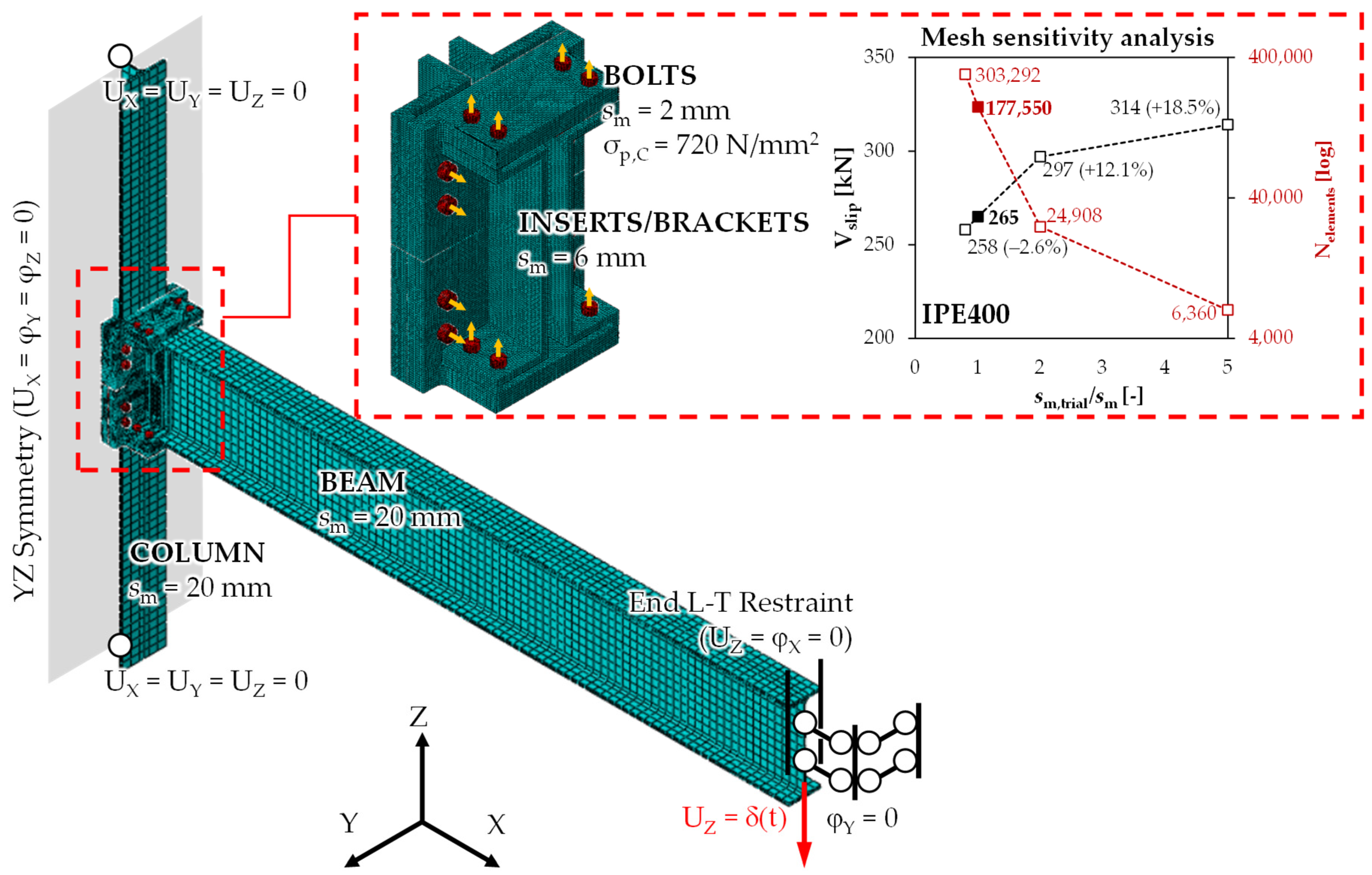
In order to account for realistic loading conditions under ULS gravity loads while balancing analysis accuracy and computational effort, subassemblages of considered steel-framed buildings were extracted at inflexion points of expected bending moment diagrams on beams and columns. Moreover, only half of the assembly was explicitly modelled, accounting for the joints’ symmetry with respect to the YZ plane. Structural continuity was hence restored through proper boundary conditions, which are depicted in
Figure 3.
Both geometric and material nonlinearity sources were explicitly accounted for in analyses. European S355 steel grade was assumed for all structural steel members and clamping components, while Class 10.9 high-strength steel was considered for bolts.
Accordingly, a mean yielding stress
fy = 1.25 × 355 = 444 N/mm
2 was assumed for beams, columns, inserts and brackets—in compliance with EN1998-1-1 prescriptions concerning material randomness [
34]—while
fyb = 898 N/mm
2,
fub = 1028 N/mm
2 were assumed for 10.9 bolts in compliance with D’Aniello et al. [
35].
Material yielding was modelled via the Von Mises criterion. In the absence of experimental calibration, combined isotropic–kinematic hardening was approximately accounted for based on indications from Dutta et al. [
36], i.e., by scaling relevant hardening parameters to match S355 steel grade. Although ductile damage was not explicitly accounted for, post-peak degrading branches were introduced in true stress–strain curves to equivalently capture possible local failure mechanisms as suggested in Milone et al. [
37].
Based on mesh sensitivity analyses and previous numerical studies carried out by the authors on bolted joints [
38], a refined mesh size
sm = 2 mm was adopted for bolts, while inserts clamping brackets were meshed assuming an average element size of ≈6 mm. Conversely, a coarser mesh (
sm ≈ 20 mm, with at least two FEs through the thickness) was used for the remaining regions of beams and columns, which were expected to remain in their elastic range.
Owing to the peculiar nature of investigated joints, all potential contact regions were carefully detected through the pair-finding algorithm included in ABAQUS 2017 [
33]. Therefore, surface-to-surface interactions were introduced to model contact. In line with previous refined numerical studies on steel friction joints [
25,
39], a “hard contact” formulation (rigid interface in compression without interpenetration, null tension with opening allowed) was assumed for the normal contact behaviour, while the tangential response was governed by a penalty-based Coulomb friction model (friction coefficient μ = 0.3—EN1993-1-8 [
26] reference value for cleaned steel surfaces without specific treatments).
The pre-tightening of fasteners was modelled through the “Bolt load” command, assuming σc,P = 0.7 fub for each bolt. Monotonic displacement histories were hence applied at (half-)beam ends to reproduce gravity load conditions, i.e., up to a beam chord rotation of θ = arctan (Δb/Lb*) = 0.02 rad, Δb being the relative vertical displacement between the beam-end and joint reference points and Lb* being their horizontal distance in the undeformed configuration. To ensure stable results in the presence of highly nonlinear behaviour, the dynamic implicit ABAQUS solver was used for FEAs. Quasi-static load increments were considered to mitigate convergence issues; this condition was verified by monitoring the energy balance throughout simulations, i.e., ensuring that kinetic energy remained negligible compared to the internal energy.
In addition to reference models, an additional set of numerical simulations was developed by assuming the beam member was infinitely elastic, whilst maintaining no change in all other modelling assumptions and loading conditions, i.e., to isolate and characterise the mechanical response of the clamped joints per se, allowing the evaluation of their vertical slip resistance and elastic stiffness.
4. Results and Discussion
4.1. Performance Assessment of Each Considered Assembly
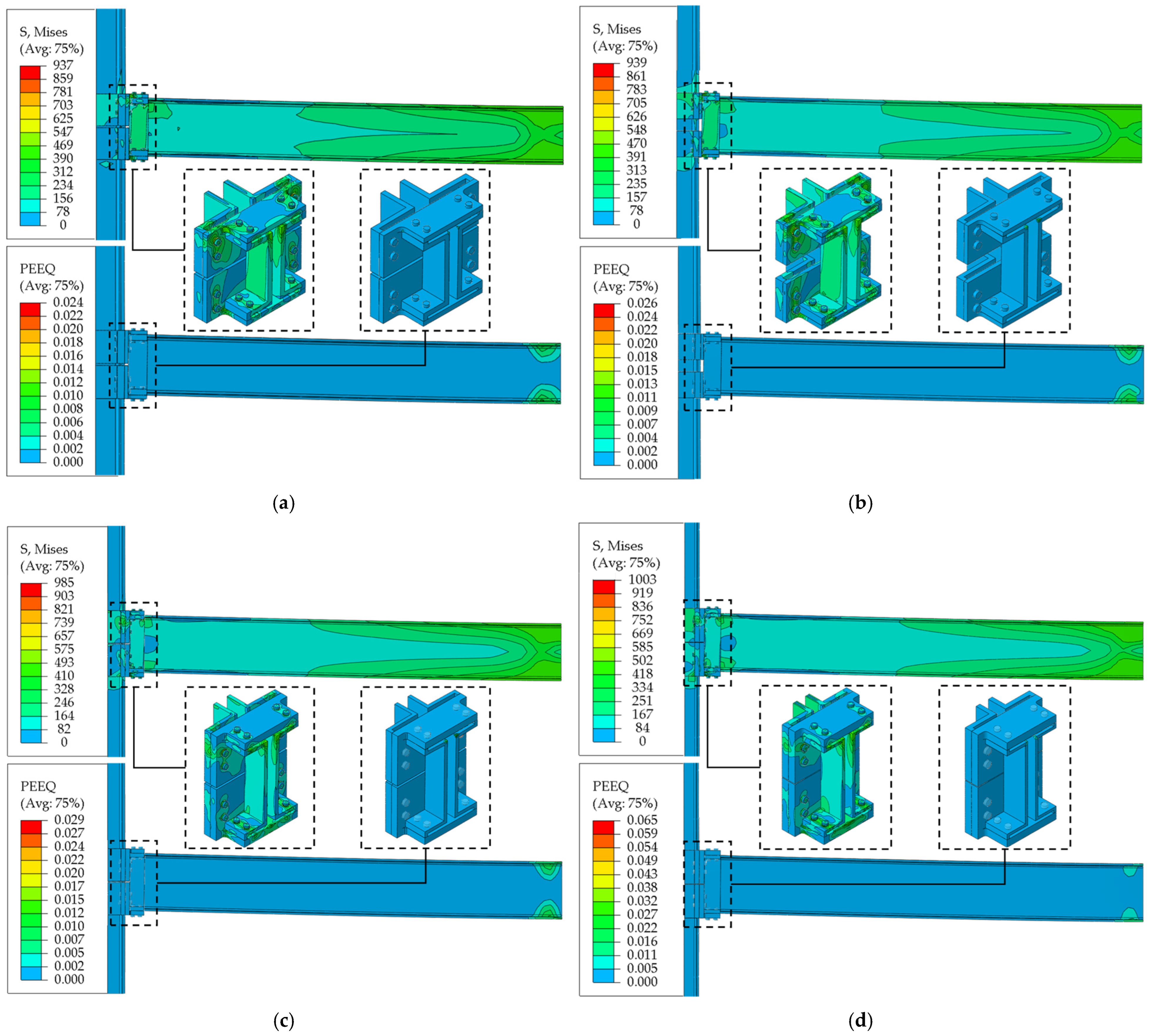
The structural performance of each considered configuration in monotonic conditions is depicted in
Figure 4 in terms of Von Mises stresses (S_MISES) and equivalent plastic strains (PEEQ =
—
εpl being the plastic strain tensor and “:” denoting the scalar product [
33]) at the peak chord rotation.
For the sake of clarity, depicted FEAs outcomes are referred to the final design iteration, in which the thicknesses of both omega inserts and L-brackets were—when needed—iteratively increased to avoid undesired loss of contact among the parts.
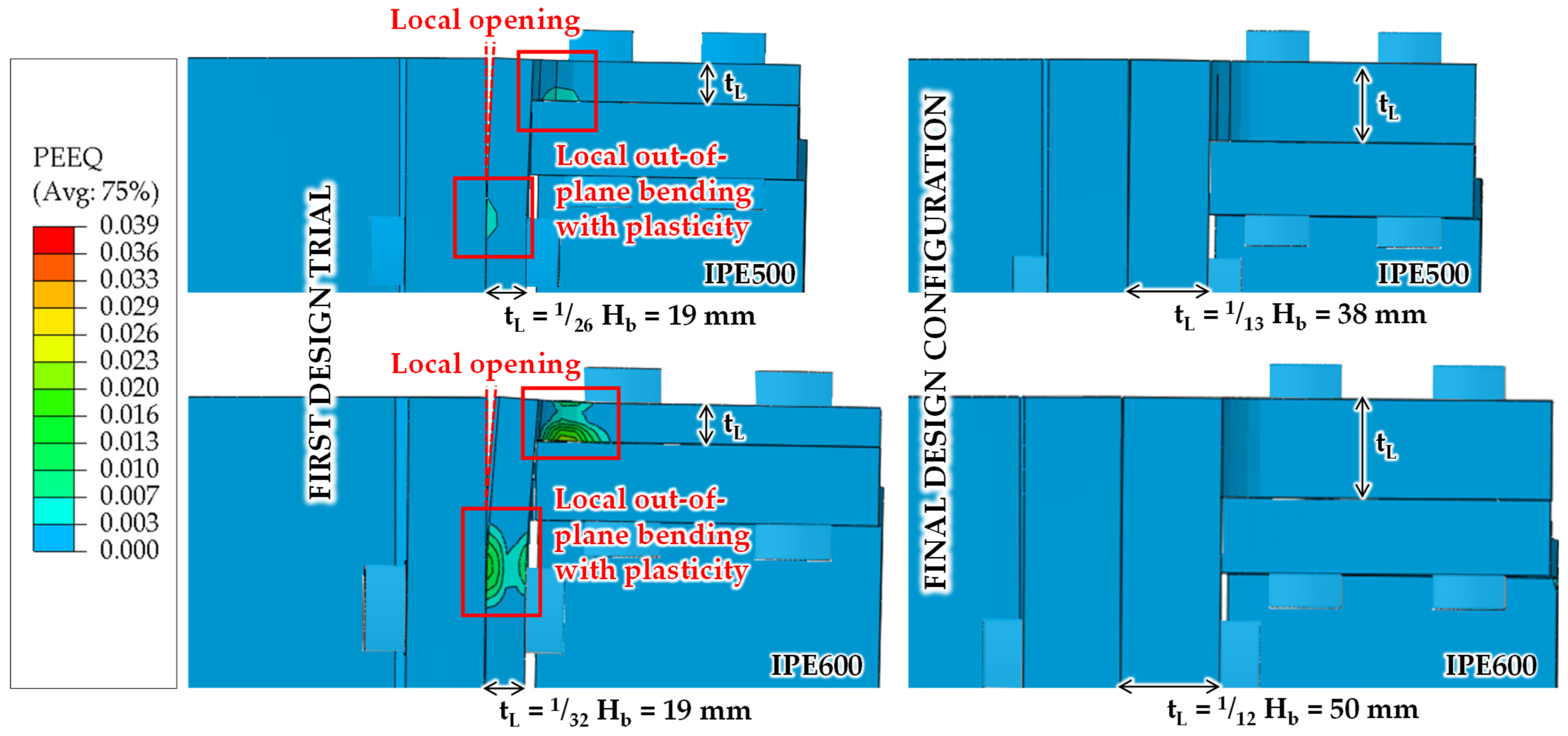
Indeed, as a first trial configuration, for each investigated beam-to-column configuration, the same thickness was initially assumed for clamping components, i.e., equal to the column-flange thickness (tL = tΩ = tfc). This preliminary choice was made to assess whether a direct relationship with the thickness of the connected column flange could already provide sufficient local stiffness to preserve the clamping action. The efficiency of trial assemblies was hence investigated by checking if the beam could develop its plastic moment at mid-span without a significant relative slip between the beam and column and/or local opening due to bending deformation of inserts/brackets.
Geometrical features of clamping components for the first and last design iterations are summarised in
Table 2. It can be easily noticed how the initial assumption on
tL and
tΩ proved to be sufficient in the case of smaller beams (IPE300, IPE400), whereas it did not result in an adequate response for IPE500 and IPE600 configurations. Indeed, in these latter cases, the increased beam depth resulted in larger local deformation demands within the clamping assembly, leading to excessive out-of-plane flexibility of the L-shaped brackets with consequent loss of contact pressure at friction interfaces and damage (see
Figure 5).
By looking at the final design outcomes, the mechanical link among the beam’s and the brackets’ response can be clearly identified. Namely, a very similar ratio Hb/tL was obtained for each case (≈13.5 on average), with the lone exception of IPE 400, for which tL = tfc was sufficient.
In light of this, Equation (12) may represent a useful preliminary criterion for sizing the L-shaped brackets. To this end, although a wider parametric study is still needed, rL = 13.5 appears as a first reasonable choice in view of a future, deeper investigation on the influence of the column stiffness—which will involve a parametric variation in columns’ profiles as well.
To partially address this issue, when deriving omega inserts’ thicknesses through Equation (13), tΩ = tfc should at least be assumed, with this condition typically governing design in the case of smaller beams. More generally speaking, for configurations that are substantially different from the ones considered in this preliminary study—e.g., in terms of member sizes, joint geometries, surface treatments, fabrication tolerances, and structural layouts—the relative stiffness among the clamping components and the column flange should be carefully checked and may involve some design iterations.
With reference to all final design configurations, the expected formation of a mid-span plastic hinge in the lone beam is confirmed by the PEEQ distributions at peak chord rotation. Conversely, L-shaped brackets and omega-shaped inserts remain essentially within the elastic range, with only negligible plasticity in corners due to moderate stress amplification. In the same fashion, bolts always behave elastically, ensuring that they can be easily dismantled in absence of shank/hole distortions.
To this end, it is worth emphasising that plasticity in beams only occurs for very large chord rotations, while the design ULS moment under gravity loads—estimated by assuming
gk = 4.5 kN/m
2,
qk = 3.0 kN/m
2 on a square-shaped footprint—only reaches 61–88% of the beam elastic moment as per EN1993-1-1 [
18]. Therefore, the reuse potential for beams and columns can be considered achieved in all cases from a mechanical perspective.
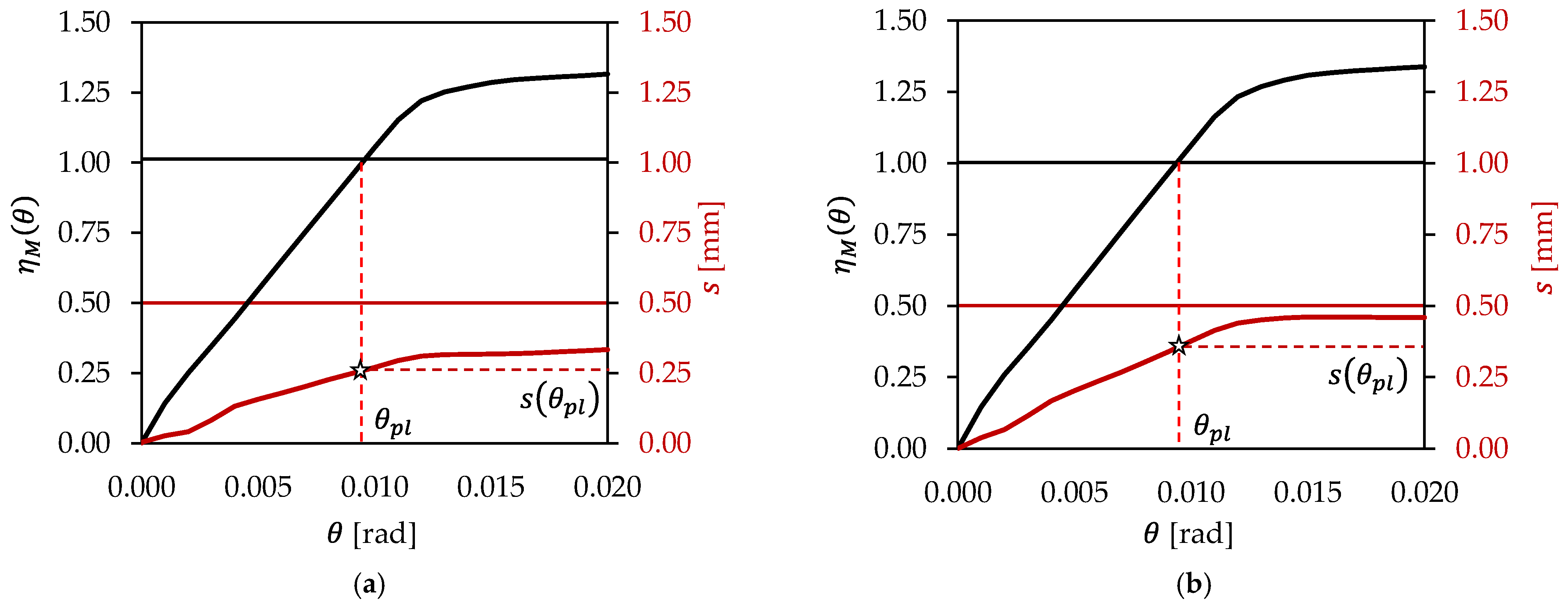
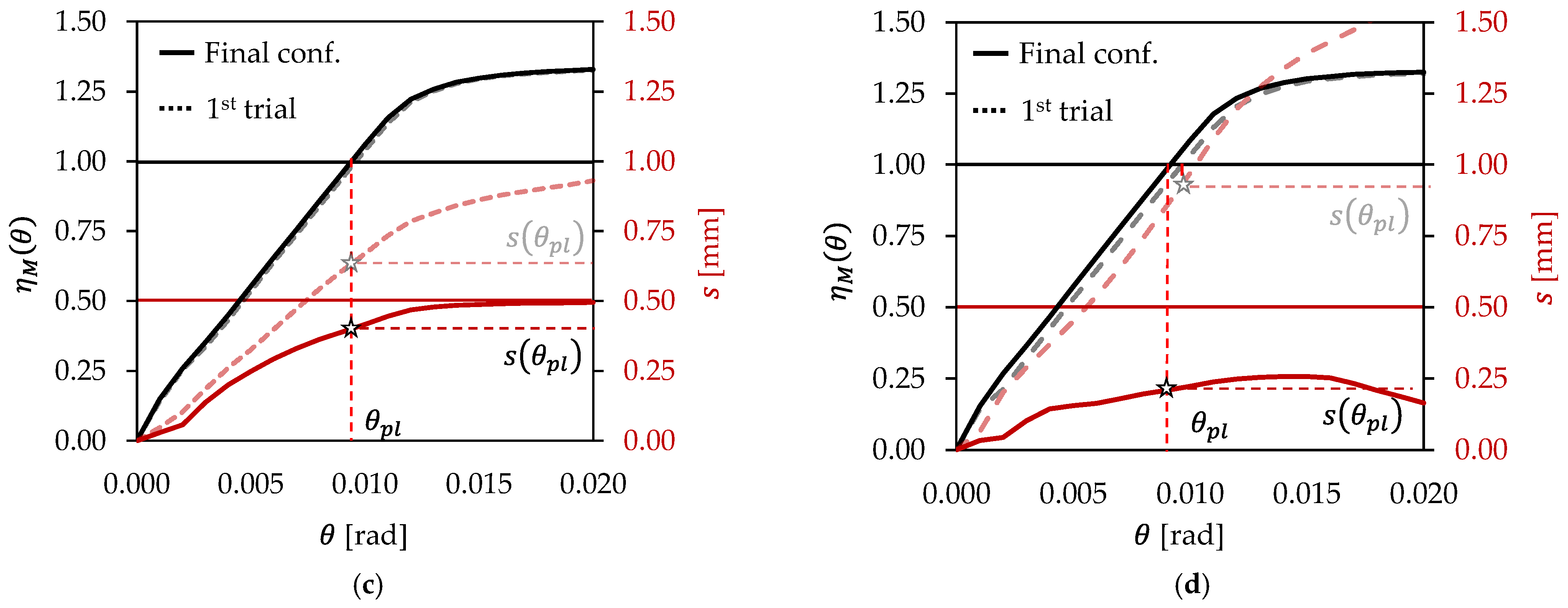
In order to further check for the occurrence of significant slips in beam-side connections—which largely contribute to joint deformability and may hinder the serviceability performance of the assembly—the mid-span bending moment Mmid developing in the beam was monitored against both chord rotations θ and beam–column relative displacements s. To provide a consistent representation of the results for each case, Mmid was normalised with respect to the nominal plastic resistance of the beam Mpl,beam = Wpl,y × fyk (ηM = Mmid(θ, s)/Mpl,beam).
The relative slip s was estimated from FEAs as the displacement difference between reference points located on the beam and column sides of the clamped interface, i.e., projected along the direction of shear transfer.
A displacement of 0.50 mm (0.02 inches) was adopted as the operational threshold for identifying significant slip (s
lim). This value is based on the slip-load identification procedure given in Appendix A of the American RCSC Specifications for Structural Joints Using High-Strength Bolts [
40]. Accordingly, the slip load is estimated as the one corresponding to either (i) a sudden increase in the slip rate or (ii) a 0.02 inch slip—whichever condition occurs earlier. Due to the observed progressive development of relative displacements in investigated connections, the latter criterion was hence used as a conventional, and yet consistent, reference for numerical comparisons.
In this regard, for each connection, the intended resistance–slip hierarchy was considered to be fulfilled if M
pl,beam was attained before reaching
slim. In other words, being
the rotation for which η
M = 1, the following condition was checked (Equation (15)):
Figure 6 depicts η
M and
s trends against increasing beam-end rotations. For the sake of clarity, reference lines are reported in correspondence with η
M = 1, i.e., to clearly identify
and
s(
), and for
s =
slim.
For the sake of comparison, response curves for IPE500 and IPE600 configurations are reported with reference to both the first trial configurations (dotted lines) and the final ones (continuous lines). It can be easily noticed how adopting an adequate L-bracket thickness effectively contrasts deformability issues due to local opening and slipping. Namely—as also reported in
Table 3—a reduction of 37% (IPE500)/66% (IPE600) in terms of
s(
) was achieved among the initial and final configurations. More generally speaking, this outcome highlights that the resistance of a friction-based clamped connection cannot be assessed solely from the nominal slip resistance of the preloaded bolts: the deformation of the components transferring the clamping force shall be controlled as well, to avoid undesired mechanical behaviour both in service and at failure.
4.2. Numerical Estimation of the Friction Resistance of the Clamped Joints
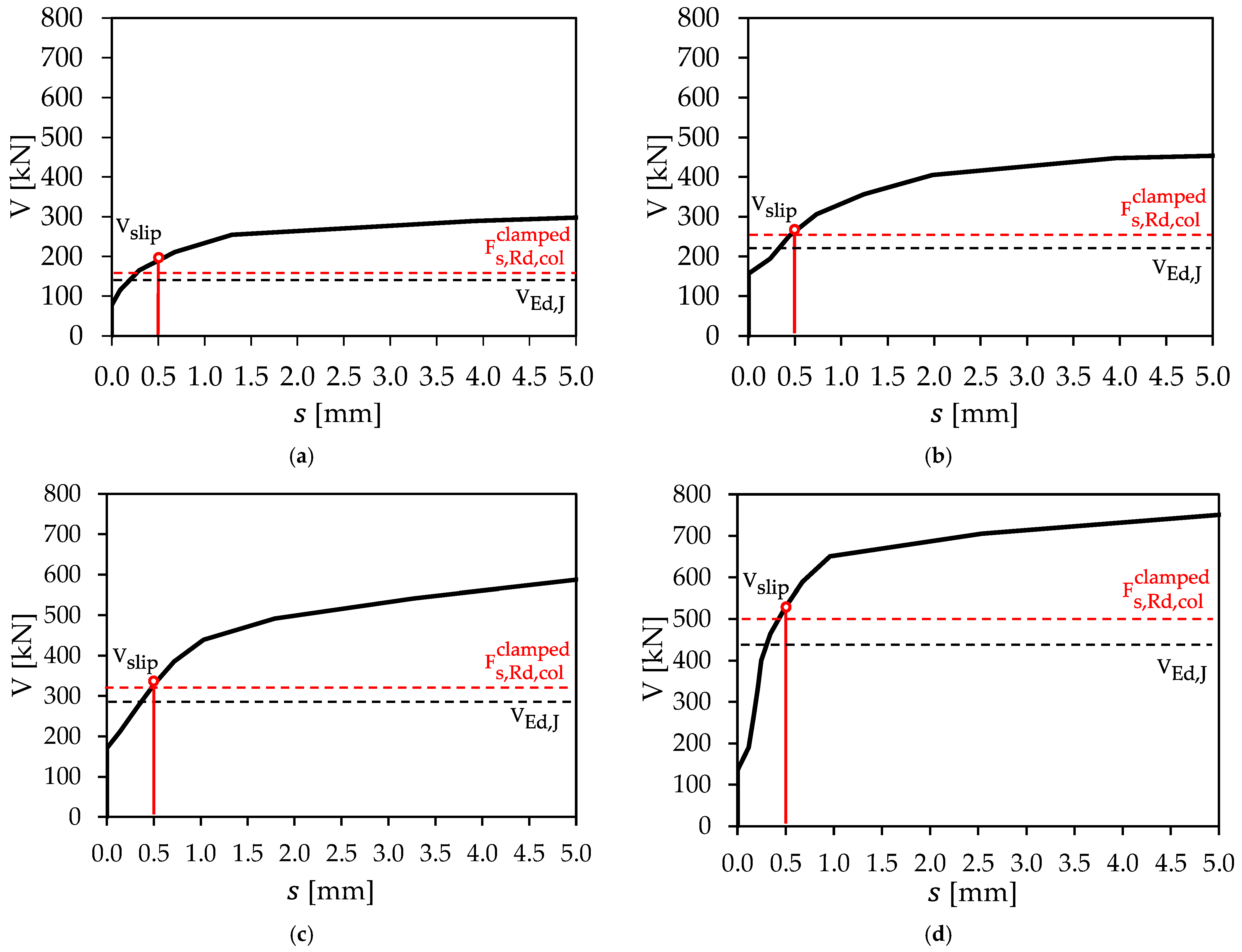
After assessing the structural performance of the entire subassembly, the indefinitely linear–elastic beam models were subsequently used to directly observe the mobilisation of the vertical friction resistance Vslip of clamped joints, i.e., for load levels beyond the ones inducing beam failure. For the sake of consistency, Vslip was once again estimated either in correspondence with the flattening of the shear–slip curve or for s = slim = 0.50 mm.
Figure 7 and
Table 4 summarise outcomes in terms of shear–slip performance for each configuration, i.e., with the indication of V
slip = V(
slim), V
Ed,J as per Equation (2) and
as per Equation (7). The clamping reduction coefficient β (Equation (3)) is also reassessed based on numerical results to check the validity of the design assumption on
la2 (compressive force assumed to act at a distance equal to one-fourth of the contact length among the member and the omega insert—see
Figure 2a).
It can be easily noticed that:
- (i)
the FEA-based slip resistance is always 1.16–1.30 times higher with respect to the joint shear demand derived via local hierarchy criteria;
- (ii)
the code-compliant vertical resistance is always comparable with Vslip, with variations (7–20%) always being on the safe side;
- (iii)
the location of the internal compressive force is between one-fourth and one-third of the relevant contact length, as slightly lower values of β (–12% on average) can be inferred from FEA results with respect to design assumptions. Still, these uncertainties are absorbed by γM2 = 1.25 in all considered cases.
With reference to the ratio Vslip/, it is worth highlighting that in all cases, its value is not greater than 1.25 (=γM2). This condition implies that the expected code-compliant resistance (i.e., estimated for γM2 = 1.00) is indeed higher than Vslip, highlighting how the analytical formulation is still not totally able to capture local effects accounted for in FE models, e.g., contact-pressure redistribution, local bending of the clamping components and partial reduction in the effective preload.
Remarkably, if a moderate variation in μ is assumed (e.g., in the range [0.25–0.35]) to potentially simulate uncertainties about surface treatments, a less than proportional change in Vslip is obtained (e.g., —13/+6% for IPE400 configuration).
Nevertheless, (i) from a practical perspective, using proper partial safety factors can still approximately cope with all the above effects and (ii) Vslip does not physically correspond to the ultimate shear resistance of the joint, but was rather defined on a conventional basis. In all cases, additional resistance develops after initial slip through bearing and other contact mechanisms, with the V-s curve starting to behave asymptotically only for s > 1.5–2.0 mm.
4.3. Joints Stiffness and Resistance Classification as per EN1993-1-8
In
Section 2.1 and
Section 2.2, (i) joint conception was addressed to minimise its expected bending stiffness and (ii) quantitative design assumptions were introduced to avoid undesired moment transmission descending from the friction resistance of the beam-side connection. To verify the above assumptions, the moment–rotation response of the clamped beam-to-column joint was classified within the framework of EN 1993-1-8 [
26] prescriptions.
Accordingly, the initial rotational stiffness of the joint S
j,ini [kNm/rad] was first expressed in a normalised form (
) as follows (Equation (16)):
where EI
b is the flexural stiffness of the main beam, spanning length L
b.
According to EN 1993-1-8, joints can be regarded as nominally pinned from a stiffness perspective if , whereas they are considered as fully rigid if , i.e., with krigid = 25 or = 8 for unbraced and braced frames, respectively.
On the other hand, nominally pinned conditions are achieved in terms of resistance when the joint capacity Mj,Rd does not exceed 0.25 Mpl,Rd,beam, while full strength performance is obtained for Mj,Rd > Mpl,Rd,beam.
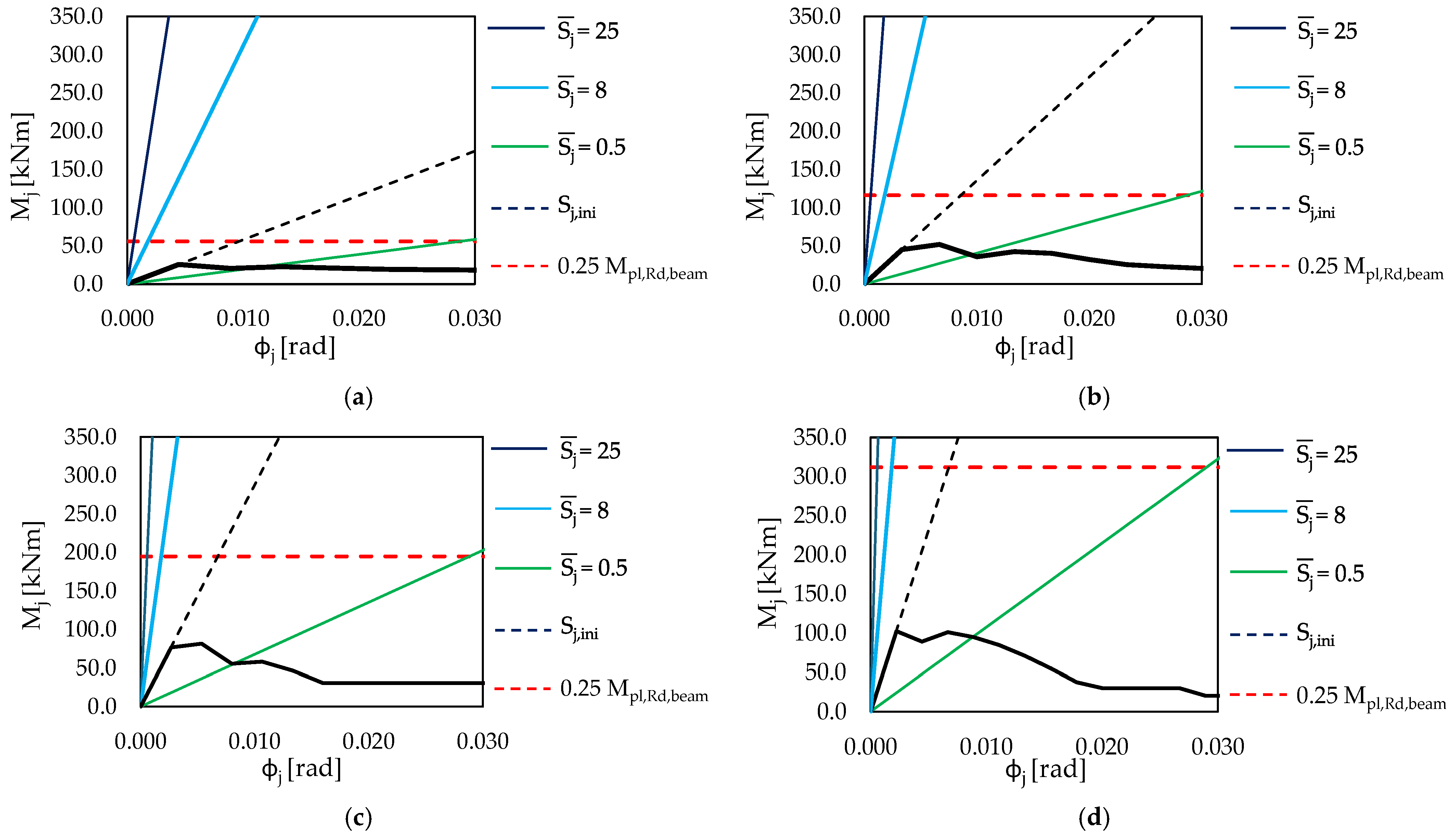
For a consistent assessment of the joint performance, (i) the relevant rotation was evaluated as the relative rotation between reference sections located on the beam and the column, i.e., to detract deformability contributions derived from the beam-elastic response, (ii) the relevant bending moment Mj was estimated by integrating FE nodal forces with reference to the inner beam-end section and (iii) was determined with a secant approach to exclude initial nonlinearity sources (microslips, local adjustments of parts in contact), i.e., deriving it through a linear approximation of the moment–rotation curve among zero and 0.4 Mj,max—Mj,max being the maximum moment as per numerical analyses.
FEA-based
curves are reported in
Figure 8 for each considered configuration. For the sake of comparison, stiffness limits for both unbraced and braced frames are depicted—i.e., to account for different uses of proposed connections in real steel buildings—as well as the relevant strength condition for nominally pinned joints. The stiffness and resistance classification results are summarised in
Table 5.
According to the results, all investigated joints can be considered as semi-rigid from the stiffness point of view. In fact, the initial rotational stiffness is higher than
, although it still remains far lower than the rigid-joint limits (i.e.,
and especially
). Clamped assemblies, hence, provide some rotational restraint, although their response is indeed far from that of a fully restrained connection. The highest stiffness levels were obtained for IPE500 and IPE600, in which thickness increase was required for L-brackets, as shown in
Section 4.1.
This outcome preliminarily suggests that—for the considered configurations—local deformability and global stiffness issues cannot be fully decoupled in design.
Conversely, all joints behave as nominally pinned from a resistance point of view, with Mj,max being at most equal to 0.12 Mpl,Rd,beam. This confirms the effectiveness of Equation (10) for the design of the beam-side connection.
It is worth remarking that the above outcomes are consistent with the behaviour commonly observed in other beam-to-column joint typologies used in GLR steel frames. In particular, flush end-plate connections (FEPCs)—which are frequently adopted in practice as nominally pinned or simple shear connections, since they are mainly intended to transfer vertical shear rather than significant bending moments [
29,
41]—also exhibit a moment–rotation response that is not perfectly pinned, and several studies have shown that FEPCs typically fall within the semi-rigid stiffness range when classified according to EN1993-1-8 [
41,
42]. This confirms that the simultaneous occurrence of limited moment resistance and non-negligible rotational stiffness is not specific to the proposed clamped connection but is a recognised feature of many steel beam-to-column joints adopted in practice.
4.4. Limitations of the Developed Solution and Numerical Study
Despite the favourable numerical response observed in previous sections for the investigated configurations, the developed connections still present some limitations that should be considered before their introduction in technical practice.
Indeed, the involved shear-transfer mechanism is governed by friction and is therefore sensitive to the actual condition of the faying surfaces, the variability of the slip factor, the accuracy of bolt preloading and the possible reduction in the clamping force over time due to relaxation, local embedding or repeated loading. Consequently, appropriate surface preparation, installation procedures and inspection requirements would be necessary to ensure that the assumed slip resistance is reliably achieved in practice.
Moreover, the relevant numerical study also showed some limitations that leave room for future investigations. Firstly, the developed numerical study will need support in the form of experimental validation, which will be the subject of future research on demountable clamped connections. This work should be therefore intended as a first proof of concept to explore the validity of the proposed solution from both a structural and deconstruction perspective.
Additionally, the sensitivity of joints’ response to other key aspects (e.g., cyclic and fatigue conditions, structural degradation, repeated dismantling, etc.) also deserves further examination. Finally, the performance of other structural layouts involving different members’ sizes needs to be investigated deeper, both through numerical and experimental assessment.