Article

Effect of Artificial Saw-Cut Notch Depth on the Bond–Slip Behavior and Modeling of CFRP-to-Concrete Interfaces

1
School of Civil and Transportation Engineering, Guangdong University of Technology, Guangzhou 510006, China
2
Beihai Vocational College, Beihai 536000, China
*
Author to whom correspondence should be addressed.
Buildings 2026, 16(15), 3111; https://doi.org/10.3390/buildings16153111
Submission received: 13 July 2026 / Revised: 1 August 2026 / Accepted: 4 August 2026 / Published: 5 August 2026
(This article belongs to the Special Issue Research on Recent Developments in Building Structures)

Abstract

Carbon fiber-reinforced polymer (CFRP) composites are widely used for strengthening concrete structures, but the bond behavior of CFRP–concrete interfaces in cracked concrete remains insufficiently understood. This study investigates the effect of saw-cut notch depth on the interfacial bond behavior between CFRP sheets and concrete through double-shear tests. Twelve specimens were prepared with saw-cut notch depths of 0, 10, 20, and 30 mm, where the crack width of the cracked specimens was fixed at 1 mm. The ultimate bearing capacity, CFRP strain transfer behavior, load-relative displacement response, interfacial bond shear stress distribution, and local bond–slip relationship were systematically analyzed. The results show that increasing saw-cut notch depth weakens both the bearing capacity and deformation capacity of the CFRP–concrete interface. Compared with the uncracked specimens, the average ultimate load decreased by approximately 5.0%, 9.2%, and 14.7% for crack depths of 10 mm, 20 mm and 30 mm. Deeper cracks promoted earlier expansion of the CFRP strain transfer region toward the free end and accelerated the development of interfacial relative displacement. The shear stress distribution further indicated that the saw-cut notch altered the interfacial stress transfer path and promoted earlier redistribution of bond shear stress along the bonded length. Based on the experimental results, an empirical normalized curve-shape function was developed to describe the effects of saw-cut notch depth and distance from the notch on the normalized local bond–slip response. Within the present dataset, the calculated curves showed general consistency with the experimental normalized curve trends, particularly in the post-peak descending branch.

1. Introduction

Concrete is one of the most widely used construction materials in building and civil infrastructure owing to its abundant raw materials, relatively low cost, good compressive strength, castability, and adaptability to different structural forms [1,2]. These advantages make concrete widely used in bridges, buildings, tunnels, industrial facilities, and other infrastructure systems. However, during long-term service, concrete structures may suffer from cracking, reinforcement corrosion, freeze–thaw damage, chemical attack, and other durability-related deterioration under the combined effects of mechanical loading and environmental exposure [3,4,5]. Such deterioration may reduce structural serviceability, durability, and load-bearing capacity. Therefore, effective strengthening and rehabilitation techniques are required to improve the safety and long-term performance of existing concrete structures.
Among various strengthening techniques, fiber-reinforced polymer (FRP) composites have been widely used in civil engineering because of their advantages, including high strength-to-weight ratio, excellent corrosion resistance, convenient construction, and high design flexibility. In particular, they have shown great potential in the strengthening and rehabilitation of existing normal concrete structures [6,7,8]. In recent years, extensive studies have been conducted on FRP-strengthened concrete structures, and significant research achievements have been reported in flexural strengthening [9,10,11], seismic strengthening, and shear strengthening [12,13].
The mechanical performance of FRP-strengthened concrete structures largely depends on the interfacial bond behavior between FRP and concrete. The ultimate bearing capacity of strengthened specimens is usually governed by the bond strength between the FRP layer and the concrete substrate [14]. As shown in Figure 1, depending on the mechanical properties of the constituent materials and the interfacial interaction mechanism, several failure modes may occur at the FRP–concrete interface, including shallow concrete substrate failure, debonding between the adhesive layer and concrete, shear failure within the adhesive layer, debonding between the FRP sheet and adhesive layer, and delamination of the FRP sheet [15,16]. Since FRP materials generally possess high tensile strength, the failure of FRP-strengthened concrete structures is typically not controlled by rupture of the FRP sheet, but rather by interfacial debonding caused by insufficient bond strength at the FRP–concrete interface. Therefore, the interfacial bond behavior is one of the key factors affecting the strengthening effectiveness and load-bearing capacity of FRP-strengthened concrete structures [17,18,19].
For the bond behavior of the FRP–concrete interface, previous studies have systematically investigated the effects of interfacial defects, FRP geometric parameters, fatigue damage, and durability. Shi et al. [20] reported that interfacial bond defects are one of the main causes of bond debonding failure. Mensah et al. [21] conducted double-shear tests and found that the width and thickness of the FRP layer have significant effects on the interfacial bond behavior between FRP and concrete. Increasing the width and thickness of the FRP layer can improve the maximum load-bearing capacity of specimens to some extent. Li et al. [22] investigated the interfacial slip behavior between CFRP and concrete with interfacial defects and established a bond strength degradation model considering the influence of such defects. Min et al. [23] proposed a fatigue life prediction model considering the interaction among different components, fatigue damage accumulation, and the effect of FRP fatigue debonding. They also proposed a stress threshold to prevent fatigue debonding of FRP.
Regarding FRP-strengthened concrete beams, Pohoryles et al. [24] investigated the contribution of FRP to the shear strengthening of concrete beams and indicated that increasing the amount of FRP can effectively improve the shear capacity and stiffness of specimens. Zhang et al. [25] found that near-surface-mounted FRP can enhance the overall stiffness and shear strength of beams and delay the development of diagonal cracks. Askar et al. [26] concluded that using multiple FRP layers with a closed wrapping scheme along the shear span can provide better shear strength and ductility. In addition, compared with a 90-degree arrangement, placing FRP layers at a 45-degree angle, approximately perpendicular to shear cracks, can more effectively improve the shear capacity of members.
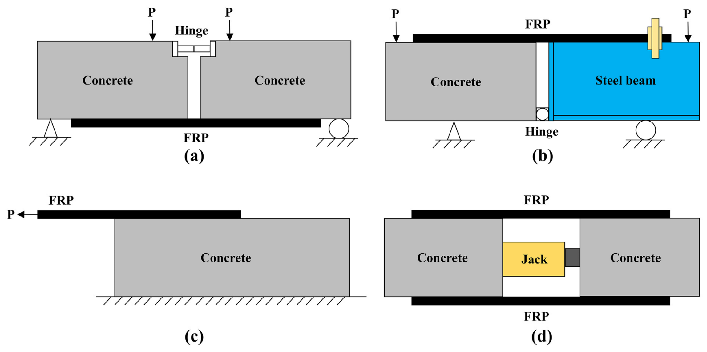
At present, the experimental methods commonly used to investigate the bond behavior of the FRP–concrete interface mainly include beam tests and modified beam tests [27,28], single-shear tests, and double-shear tests [29], as shown in Figure 2. Among them, the double-shear test is considered an effective method for studying the bond–slip relationship of the FRP–concrete interface because of its clear force transfer path and relatively well-defined boundary conditions. For example, Wang et al. [30] proposed an ultimate load prediction model for the FRP–concrete interface based on double-shear tests. Ferrier et al. [31] used double-shear tests to investigate the durability of FRP–concrete bonded joints and emphasized the importance of interfacial durability in maintaining the overall performance of strengthened structures.
Studies relevant to CFRP strengthening of pre-cracked or notched concrete have also been conducted within the broader field of FRP–concrete bonding. Mohammadi et al. [32] used simple notched-beam specimens to represent an existing flexural–shear crack and investigated intermediate-crack debonding and the associated FRP–concrete bond–slip response. Their tests showed that debonding initiated from the tip of a diagonal crack near the notch or from a flexural crack at the beam midspan. Dai et al. [33] investigated unidirectional FRP sheets externally bonded to notched concrete beams under dowel loading and evaluated mixed-mode interfacial peeling while considering parameters including the pre-crack length, concrete strength, FRP tensile stiffness, adhesive properties, and surface treatment. Zheng et al. [34] subsequently developed an analytical approach for FRP-plated notched concrete beams by coupling Mode II interfacial debonding with Mode I concrete crack propagation. These studies demonstrate that concrete cracking or notching can alter the local stress state and debonding process of an externally bonded FRP system. However, their responses were obtained from beam-type specimens and were simultaneously influenced by member flexure, concrete crack propagation, and mixed-mode loading.
Modified local bond–slip formulations have also been proposed for FRP–concrete interfaces subjected to different forms of degradation or substrate damage. Biscaia et al. [35] proposed a two-parameter local bond–slip model for artificially aged GFRP–concrete joints, with the parameters determined from experimental results under different environmental exposure conditions. Lv et al. [36] developed a nonlinear local bond–slip model for FRP laminates externally bonded to thermally damaged concrete by extending an existing two-parameter formulation and relating the response to the interfacial fracture energy and brittleness index. These studies confirm that degradation of the bonded interface or damage to the concrete substrate can alter the local bond–slip response. Nevertheless, the corresponding damage variables mainly describe environmental aging or distributed thermal damage rather than a controlled transverse discontinuity with a specified depth and spatial position.
Although the above studies have advanced the understanding of FRP debonding from cracked, notched, aged, or otherwise damaged concrete substrates, two limitations remain. First, studies involving predefined cracks or notches have mainly adopted beam-type specimens, for which the measured response is affected by member flexure, concrete crack propagation, and mixed-mode loading. Second, existing damage-dependent bond–slip formulations generally represent deterioration through environmental exposure parameters, distributed substrate damage, or interfacial defect characteristics and do not explicitly describe the spatial variation in local bond behavior around a controlled transverse saw-cut notch. Consequently, the combined effects of saw-cut notch depth and distance from the notch on the normalized local CFRP–concrete bond–slip response have not been sufficiently clarified.
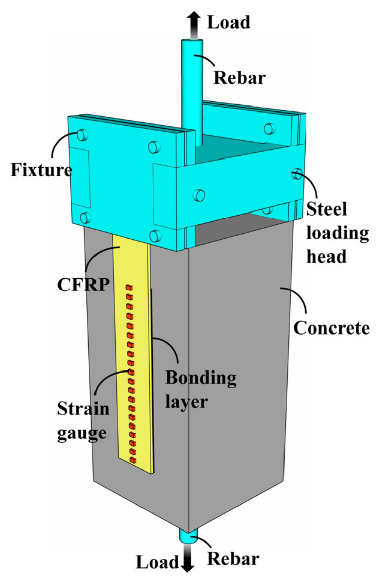
Based on this background, the present study adopts the double-shear test method to investigate the effects of saw-cut notch depth in concrete specimens and the distance from the CFRP–concrete interfacial measurement point to the saw-cut notch on the local bond–slip curve. To more accurately reveal the bond stress transfer mechanism of the CFRP–concrete interface under saw-cut notch conditions, an optimized double-shear loading scheme is adopted, as shown in Figure 3. Furthermore, based on the normalized bond–slip curve form proposed by Lu [37], an empirical normalized curve-shape function was developed to describe the effects of saw-cut notch depth and distance from the notch on the local normalized bond–slip response. The proposed function is intended to characterize the normalized curve shape within the tested range rather than to independently predict the dimensional bond–slip parameters.
Accordingly, the specific contribution of this study is to experimentally examine the combined effects of saw-cut notch depth and spatial distance from the notch on the local CFRP–concrete bond-transfer response under double-shear loading and to develop, within the tested range, an empirical normalized curve-shape function incorporating these two variables.

2. Experimental Details

2.1. Specimen Design

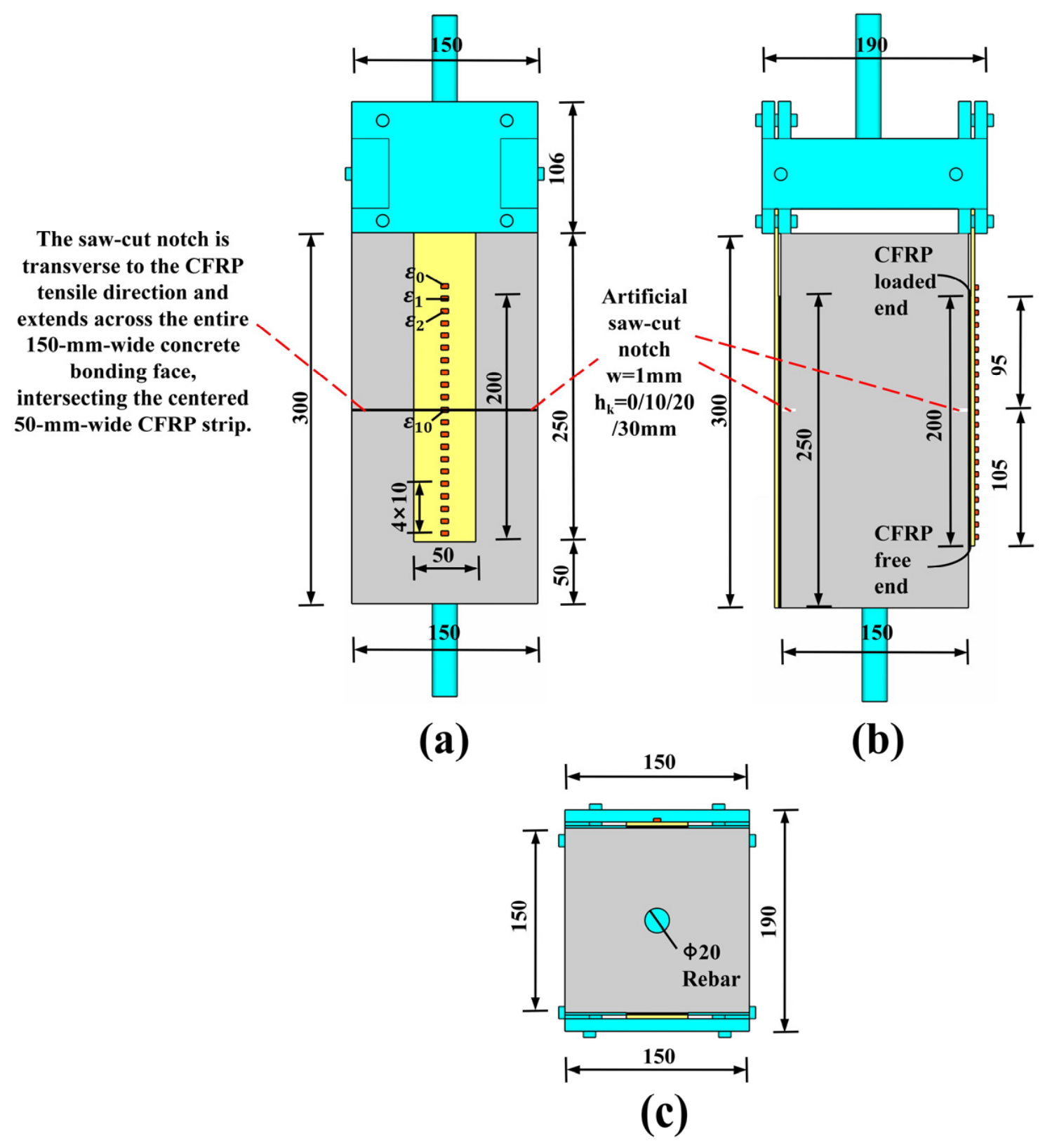
A total of 12 specimens were fabricated in this study. According to the depth of the artificial saw-cut notch, the specimens were divided into four groups, with three repeated specimens in each group. Each specimen consisted of four main components: concrete, CFRP sheet, epoxy resin adhesive, and auxiliary steel bars for load transfer. The dimensions of the concrete block were 300 mm × 150 mm × 150 mm, and the dimensions of the CFRP sheet were 200 mm × 50 mm × 0.25 mm. The detailed dimensions of the specimens are shown in Figure 4.
Before CFRP bonding, a transverse saw-cut notch was introduced into the concrete bonding face. The notch extended across the full width of the 150 mm wide concrete face and therefore intersected the entire width of the centered 50 mm wide CFRP strip. Its centerline was located 95 mm from the CFRP-loaded end and 105 mm from the free end. The nominal notch width was 1 mm. The investigated notch-depth levels were (hk = 0), 10, 20, and 30 mm, where (hk = 0) denotes the unnotched control specimens.
The epoxy resin adhesive used in the test was Shenliling epoxy resin adhesive, consisting of components A and B, which were mixed at a volume ratio of 1:1 before application. HRB400-grade steel rebars were used as auxiliary load-transfer reinforcement.
In the specimen designation, “NC” denotes normal concrete, “W” denotes the width of the artificial saw-cut notch, and “D” denotes the depth of the artificial saw-cut notch. For example, NC-W1D20-1 represents a normal concrete specimen with an artificial saw-cut notch introduced by saw cutting, where the crack width is 1 mm and the crack depth is 20 mm. The suffix “1” indicates the first repeated specimen in this group. The main parameters of all specimens are listed in Table 1.

2.2. Specimen Fabrication

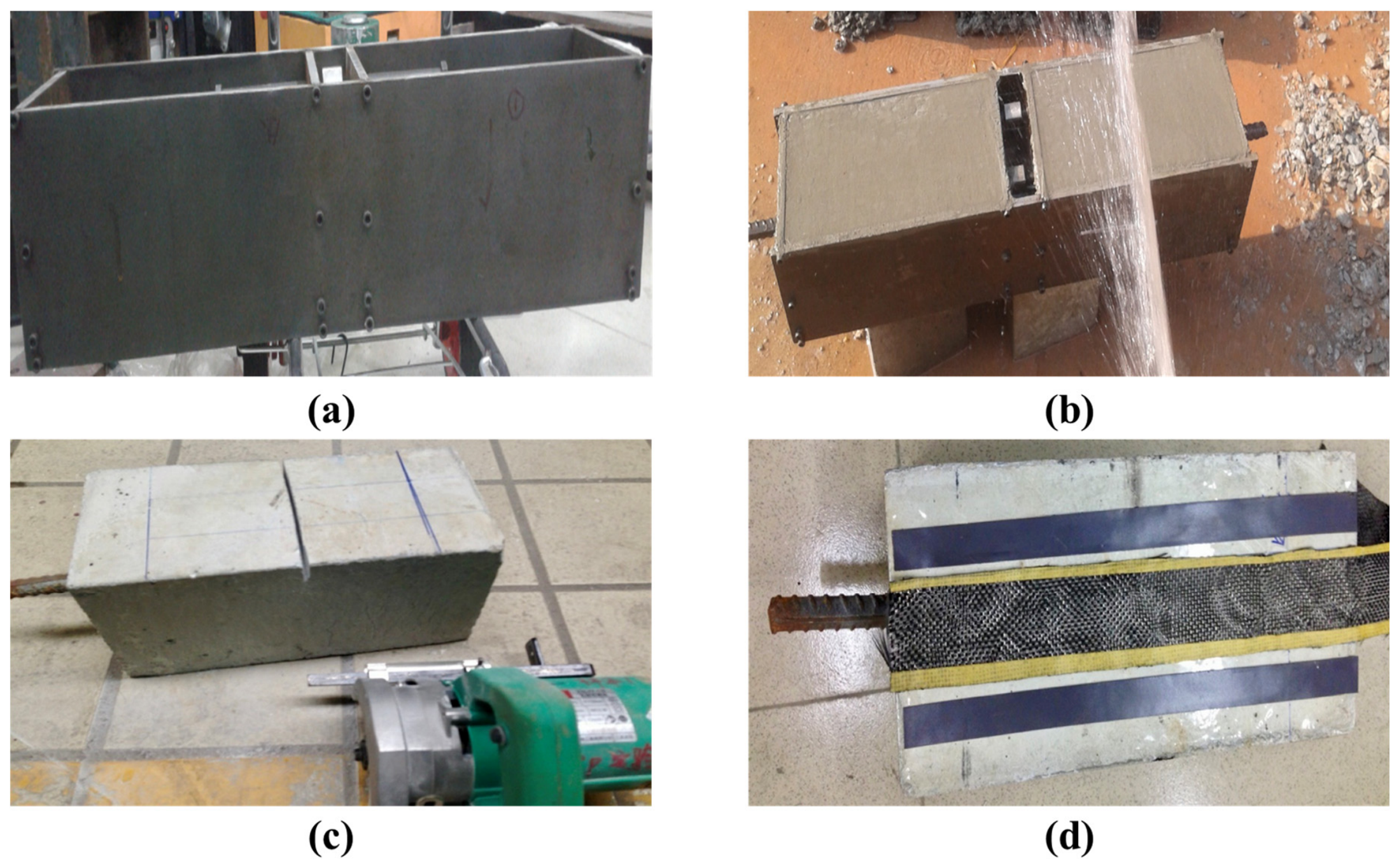
The specimen preparation process included formwork fabrication, concrete casting and curing, CFRP sheet bonding, and end anchorage. First, the formwork was fabricated according to the designed dimensions, and the concrete was then cast, as shown in Figure 5a. After casting, the concrete specimens were subjected to standard curing and were subsequently demolded, as shown in Figure 5b. Subsequently, the concrete bonding surfaces were ground, cleaned, and marked, and the transverse saw-cut notches were introduced according to the test design, as shown in Figure 5c. The CFRP sheets were bonded to the designated regions using epoxy resin adhesive when the concrete specimens were 42 days old. During the bonding process, rolling was performed to ensure a uniform adhesive layer thickness and to eliminate visible air bubbles, as shown in Figure 5d. The specimens were then cured at room temperature for 5–7 days until the adhesive had fully hardened, after which the displacement measurement devices were installed.
Before CFRP bonding, the concrete bonding surface was mechanically ground. Dust was removed with cotton yarn two to three times, after which the surface was wiped with cotton yarn and acetone two to three times. During adhesive application, 1 mm thick spacers were placed along both sides of the bonded region to improve the uniformity of adhesive application. The actual cured adhesive-layer thickness and quantitative surface roughness were not measured, and the elastic modulus and tensile strength of the epoxy adhesive were unavailable in the existing material records. Therefore, the independent effects of these parameters on the CFRP-to-concrete interfacial bond response could not be evaluated in the present study.
No filling or sealing treatment was applied to the 1 mm saw-cut notch before CFRP bonding. Transparent tape was applied only to the non-bonded surface areas to control adhesive overflow. Therefore, limited local epoxy ingress into the notch may have occurred, although its extent was not measured. Accordingly, the experimental variable represents the depth of an artificial saw-cut notch formed under the adopted bonding procedure, rather than the depth of an idealized, fully traction-free natural crack.
To prevent slippage of the CFRP sheet or pull-out of fiber bundles during loading, aluminum plates were used to strengthen the loaded end. In addition, the free end of the CFRP sheet was wrapped around a high-strength bolt to provide reliable anchorage, thereby ensuring that the CFRP sheet could fully develop its load-bearing capacity during the test.

2.3. Material Properties

The detailed mix proportion of the C40 concrete used in this study is listed in Table 2. The mechanical properties of the normal concrete were tested in accordance with the Chinese Standard for Test Methods of Concrete Physical and Mechanical Properties [38]. The cube compressive strength, denoted as fcu, was determined using three 150 mm cubic specimens. The cylinder compressive strength, denoted as fc, was determined using three cylindrical specimens with a diameter of 150 mm and a height of 300 mm. The measured 28-day average cube compressive strength of the C40 concrete was 48.58 MPa, while the measured 28-day average cylinder compressive strength was 38.35 MPa.
The A/B epoxy adhesive was mixed at a volume ratio of 1:1, with a recorded mass ratio of 1:0.9. The product information reported a standard shear strength of 14 MPa for an aluminum-to-aluminum bonded joint. This value should not be interpreted as the shear strength of the CFRP-to-concrete interface. The elastic modulus and tensile strength of the epoxy adhesive were not available in the existing material records.
The CFRP used in this study was UT70-30 carbon fiber fabric manufactured by Toray Industries, Inc., Japan. Its material properties were tested in accordance with the Chinese standard Code for Safety Appraisal of Engineering Structural Strengthening Materials [39], and the corresponding results are summarized in Table 3.

2.4. Measurement of Interfacial Bond Shear Stress and Slip

To obtain the local mechanical and deformation responses of the CFRP–concrete bonded interface along the bonded length, surface-mounted electrical resistance strain gauges were used to measure the longitudinal axial strain distribution of the CFRP sheet. The interfacial bond shear stress and slip were then calculated based on the measured relative displacement at the loaded end. To avoid conceptual confusion between discrete strain measurement points and continuous interfacial mechanical quantities, the coordinate direction, measurement point numbering, and physical meanings of the related calculated quantities are defined as follows.
Taking the free end of the CFRP sheet as the coordinate origin, a one-dimensional coordinate axis x was established along the tensile direction of the CFRP sheet. In other words, the positive direction of the x-axis was defined from the free end of the CFRP sheet to the loaded end. Surface-mounted electrical resistance strain gauges were arranged along the longitudinal centerline of the CFRP sheet to measure the axial strain of the CFRP sheet at different positions. The strain measurement points located at distances of 5 mm, 15 mm, 25 mm, …, 195 mm, and 205 mm from the free end of the CFRP sheet were sequentially numbered as i = 20, 19, 18, …, 0. It should be noted that, although the coordinate x was defined with the CFRP-free end as the origin, as shown in Figure 4a,b, the strain gauges were indexed from the loaded end toward the free end to facilitate the subsequent discrete integration of interfacial slip. The position of measurement point i was denoted as xi, and the spacing between adjacent strain measurement points was denoted as Δx. In this test, Δx was 10 mm.
The axial strain measured at strain measurement point i was denoted as εi. Since the CFRP sheet used in this study had a relatively small thickness and the interfacial calculation was based mainly on the variation in the axial tensile force of the CFRP sheet, the strain distribution through the thickness of the CFRP sheet was assumed to be uniform. Therefore, the axial strain measured by the surface-mounted strain gauge was considered to represent the average axial strain of the CFRP sheet at the corresponding cross-section. The CFRP sheet was also assumed to remain linearly elastic within the strain range of the test. Accordingly, the local axial stress in the CFRP sheet at strain measurement point iii was calculated as
σ f , i = E f ε i
where σf,i is the local axial stress in the CFRP sheet at the cross-section corresponding to strain measurement point i; Ef is the axial elastic modulus of the CFRP; and εi is the measured axial strain of the CFRP at strain measurement point i.
To obtain the relative displacement, Δw, between the concrete specimen and the steel loading head, a displacement sensor contact block was fixed at the intersection between the centerline on the side surface of the concrete specimen and the line connecting the starting sections of the CFRP-loaded ends on both sides. The displacement sensor was installed at the corresponding position on the side centerline of the steel loading head, so that the sensor probe remained in stable contact with the contact block along the loading direction. During the test, the displacement recorded by the displacement sensor was used to represent the relative displacement, Δw, between the steel loading head and the concrete specimen. This displacement was further used as the boundary displacement condition for the subsequent calculation of interfacial slip.
Referring to the testing methods for local bond shear stress and slip of CFRP–concrete interfaces proposed by Han [40] and Zheng [41], the local interfacial bond response was calculated based on the variation in the axial strain of the CFRP sheet between adjacent strain measurement points. Since the strain gauges were discretely arranged at a center-to-center spacing of 10 mm, the bond shear stress obtained by direct finite differencing of adjacent strain measurements was not a strict pointwise shear stress. Instead, it represented the average bond shear stress over the 10 mm CFRP–concrete interface segment between strain gauges i and i + 1. BHF350-2AA resistance strain gauges with a 2 mm × 2 mm active grid were used, and the manufacturer-reported gauge factor was 2.12 with a tolerance of approximately ±0.5%. No numerical smoothing or fitted differentiation was applied before the finite-difference calculation. To characterize the local bond behavior of the interface, the segment-average bond shear stress was denoted by τi, and its representative position, xτ,i, was assigned to the midpoint between the two adjacent strain gauges. The first-order strain-measurement contribution to the uncertainty of τi was also considered. These quantities were calculated as follows:
τ i = E f t f Δ x ε i + 1 ε i x τ , i = x i + x i + 1 2 u ε τ i = E f t f Δ x u 2 ε i + u 2 ε i + 1
where τi is the segment-average interfacial bond shear stress, in MPa, over the 10 mm CFRP–concrete interface segment between strain gauges i and i + 1; xτ,i is the representative coordinate of τi, assigned to the midpoint of the corresponding interface segment and measured from the CFRP-free end, in mm; xi and xi+1 are the coordinates of adjacent strain measurement points i and i + 1, in mm; Ef is the axial elastic modulus of the CFRP, in MPa; tf is the effective thickness of the CFRP, in mm; εi and εi+1 are the measured axial strains of the CFRP at adjacent strain measurement points i and i + 1 and are dimensionless when expressed in their basic form; Δx is the center-to-center spacing between adjacent strain gauges, in mm; u(εi) and u(εi+1) are the standard uncertainties associated with the two adjacent strain measurements and are dimensionless; and uεi) is the first-order propagated standard uncertainty of τi arising from the strain-measurement uncertainties, in MPa. The subscript ε indicates that this term accounts only for the strain-measurement contribution.
After obtaining the average interfacial bond shear stress τi for each interface segment, the corresponding interfacial slip was further calculated. The slip Si at representative point i on the interface is defined as the relative axial displacement between the CFRP sheet and the concrete substrate, including the adhesive-impregnated layer, at this position, which can be expressed as:
S i = S f , i S c , i
where Sf,i denotes the axial displacement of the CFRP sheet at representative point i, and Sc,i denotes the axial displacement of the concrete substrate and the adhesive-impregnated layer at the same position.
Since the local interfacial slip is difficult to measure directly, the discrete strain integration method proposed by Ferracuti et al. [42,43] was adopted in this study. Based on the discrete strain data measured along the bonded length of the CFRP sheet, and using the measured relative displacement at the loaded end as the boundary displacement condition, the axial strain of the CFRP sheet was discretely integrated along the negative direction of the x-axis, namely from the loaded end toward the free end. Through this method, the axial displacement distribution of the CFRP sheet along the bonded length was obtained, and the interfacial slip between the CFRP sheet and the concrete substrate, including the adhesive-impregnated layer, was further calculated. The slips at representative point 0 and representative point i are expressed as follows:
S 0 = Δ x ε 0 2 Δ w S i = S i 1 ε i + ε i 1 Δ x 2 ,   i 1
where S0 is the interfacial slip at representative point 0; Si is the interfacial slip at representative point i; Si−1 is the interfacial slip at representative point i − 1; Δx is the spacing between two adjacent strain measurement points; Δw is explicitly defined as the measured system-relative displacement between the concrete specimen and the steel loading head, and ε0, εi, and εi−1 are the axial strains measured by the CFRP surface-mounted strain gauges at the corresponding measurement points.

2.5. Specimen Installation and Loading Procedure

To prevent local debonding failure at the edge of the concrete specimen during loading and to ensure that the CFRP–concrete interface was mainly subjected to shear, a 50 mm spacing was reserved between the CFRP bonding region and the edge of the concrete specimen. In this test, the designed bonded length of the CFRP sheet, L, was 200 mm. According to the method proposed by Chen et al. [44] for calculating the effective bond length of CFRP, the effective bond length of the CFRP sheet, Le, was calculated to be 97.8 mm. The effective bond length Le represents the critical length required for the CFRP–concrete interface to fully develop its bond stress transfer capacity. In this test, Le was smaller than L, indicating that the designed bonded length was sufficient to satisfy the requirement for effective interfacial load transfer. To make the actual bonded length involved in load transfer close to the effective bond length and to control the interfacial failure region, an artificial saw-cut notch was introduced at a distance of 95 mm from the CFRP-loaded end, corresponding to a distance of 105 mm from the CFRP-free end. The crack width of 1 mm was selected to represent a visible saw-cut notch while maintaining a controllable and repeatable crack geometry during specimen preparation. The crack depths of 10, 20, and 30 mm corresponded to approximately 6.7%, 13.3%, and 20.0% of the concrete specimen thickness, covering shallow to relatively deep saw-cut notch conditions within the laboratory specimen scale. In addition, the crack was placed at a distance of 95 mm from the CFRP-loaded end, which was close to the calculated effective bond length of 97.8 mm. This arrangement allowed the crack to intersect the main interfacial stress transfer region, thereby facilitating the evaluation of the influence of saw-cut notch depth on local bond–slip behavior.
To ensure that the CFRP sheet was uniformly stressed in the clamping region at the loaded end, aluminum plates were bonded to both surfaces of the CFRP sheet inserted into the steel loading head using epoxy resin adhesive. Meanwhile, to prevent the longitudinal fibers at the end of the CFRP sheet from being pulled out before failure of the CFRP–concrete interface, an additional length of approximately 50 mm was reserved at the end of the CFRP sheet away from the bonded interface. This portion was wrapped around and bonded to the surface of a high-strength bolt, so that the CFRP sheet and the high-strength bolt formed an integrated anchorage system.
To verify the stress uniformity of the CFRP sheet, three strain gauges were bonded side by side along the width direction at a distance of approximately 20 mm from the CFRP-loaded end. Preloading was conducted before the formal test. When the strain responses of the three strain gauges showed consistent trends and no obvious eccentric loading characteristics were observed, the stress state of the CFRP sheet was considered to be basically uniform. Otherwise, the specimen position or clamping condition was adjusted until the requirement was satisfied.
The double-shear tests were conducted when the concrete specimens were 56 days old. After specimen preparation and installation of the measurement instruments, each specimen was placed on the tensile testing machine, and the loaded end of the CFRP sheet was clamped into the steel loading head. The formal test was conducted under load control, with a loading rate of approximately 0.1 kN/s. During loading, the surface strain of the CFRP sheet and the relative displacement Δw between the concrete specimen and the steel loading head were synchronously recorded using a DH-3816 multi-channel static strain testing system. The sampling frequency was 1 Hz.

3. Experimental Results

For each saw-cut notch depth, the three repeated specimens exhibited consistent trends in ultimate load, CFRP strain distribution, load-relative displacement response, and interfacial bond shear stress distribution. In particular, the main features of the curves, including the expansion of the strain transfer region, the shift in the transition load level, and the migration of the internal shear stress peak, were generally similar among the repeated specimens. Therefore, the first group of specimens was selected as a representative set for detailed discussion to avoid repetitive descriptions, while the second and third groups were used to confirm the repeatability and reliability of the observed trends.

3.1. Failure Modes

The governing failure modes of all 12 specimens are summarized by saw-cut notch depth in Table 4. As shown in the table, the specimens in all four groups exhibited the same governing failure mode, which was classified as cohesive debonding within the near-surface concrete substrate.
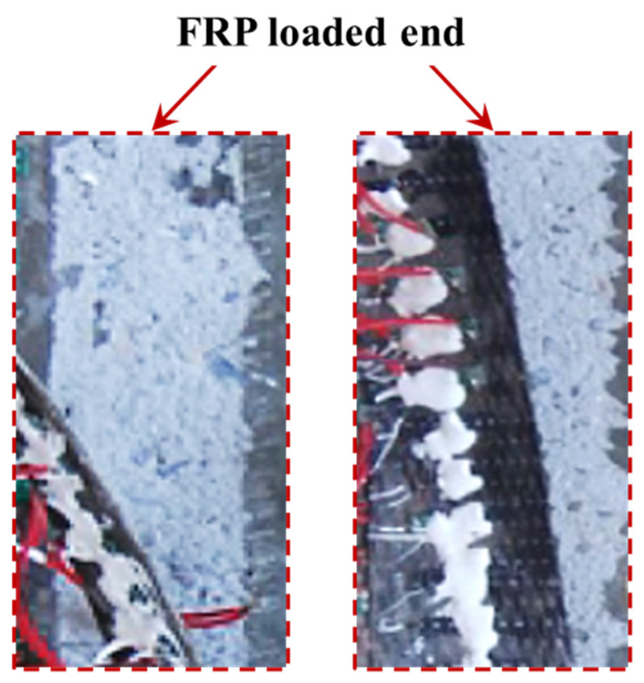
Figure 6 presents representative photographs of this failure mode. A thin layer of near-surface concrete remained attached to the detached CFRP layer, indicating that the debonding path developed within the concrete adjacent to the CFRP–concrete bonded interface rather than entirely along the adhesive-concrete or CFRP-adhesive interface. No CFRP rupture, premature end failure, or anchorage-slip failure was observed during the tests. These observations confirm that the governing failure occurred within the intended CFRP–concrete bonded region rather than through rupture of the CFRP sheet or failure of the end-anchorage system.

3.2. Effect of Saw-Cut Notch Depth on the Interfacial Ultimate Bearing Capacity

As shown in Table 5, when the artificial saw-cut notch depths were 0, 10, 20, and 30 mm, the average ultimate loads of the specimens were 28.97, 27.51, 26.31, and 24.70 kN. Taking the specimen without an artificial saw-cut notch as the reference, the ultimate load decreased by approximately 5.0%, 9.2%, and 14.7% when the crack depth increased from 0 mm to 10, 20, and 30 mm. In addition, the average ultimate relative displacements, Δw, between the concrete specimen and the steel loading head were 0.36, 0.32, 0.28, and 0.25 mm. These values showed an overall decreasing trend with increasing crack depth. The above results indicate that increasing the crack depth weakens both the ultimate bearing capacity and deformation capacity of the CFRP–concrete interface.
As the artificial saw-cut notch depth increased, the local integrity of the concrete near the crack tip was reduced, and the effective load-bearing region became smaller. As a result, stress concentration and tensile crack propagation were more likely to occur near the crack. Meanwhile, a larger crack depth expanded the disturbance range of the crack in the surrounding concrete substrate and the CFRP–concrete interface, leading to a more nonuniform distribution of interfacial shear stress and promoting the premature development of local bond damage.
Therefore, increasing the crack depth weakens the restraining effect of the concrete near the crack on the CFRP sheet, reduces the effective bond strength of the CFRP–concrete interface, and promotes the premature initiation or accelerated propagation of interfacial debonding. Consequently, the ultimate load of the specimen and the ultimate bearing capacity of the interface are reduced.
To further evaluate the repeatability of the test results, the mean value, standard deviation, and coefficient of variation in the ultimate load and ultimate relative displacement were calculated, as summarized in Table 6 and Table 7. The COV values of the ultimate load for the four saw-cut notch-depth groups were 0.98%, 1.11%, 0.46%, and 0.41%, indicating good repeatability of the ultimate-load results. The corresponding COV values of the ultimate system-relative displacement were 2.78%, 1.79%, 5.39%, and 4.68%. Although the displacement COV values were higher than those of the ultimate load, they all remained below 6%, indicating acceptable repeatability of the ultimate system-relative displacement within the present test series. Moreover, the displacement COV did not increase monotonically with saw-cut notch depth, suggesting that increasing notch depth did not systematically increase the variability of the ultimate system-relative displacement. Compared with the uncracked specimens, the ultimate load decreased by 5.0%, 9.2%, and 14.7% for crack depths of 10, 20, and 30 mm, whereas the corresponding ultimate relative displacement decreased by 10.2%, 21.3%, and 31.5%. Therefore, the deformation capacity of the CFRP–concrete interface was more sensitive to saw-cut notch depth than the bearing capacity. When the crack depth increased to 30 mm, the reduction in ultimate relative displacement was approximately 2.14 times that of the ultimate load.
One-way ANOVA indicated that notch depth had a statistically significant effect on both the ultimate load F(3,8) = 196.59, p < 0.001 and the ultimate system-relative displacement F(3,8) = 57.78, p < 0.001. Pairwise Welch’s t-tests were conducted to compare each notched group with the unnotched group, and the resulting p-values were adjusted for three comparisons using the Holm procedure. For the ultimate load, the Holm-adjusted p-values were 0.0039, 0.0023, and 0.0014 for notch depths of 10, 20, and 30 mm. In particular, the 5.0% reduction in the mean ultimate load for the 10 mm notch-depth group remained statistically significant after the Holm adjustment. For the ultimate system-relative displacement, the corresponding adjusted p-values were 0.0100, 0.0066, and 0.0007. The two-sided 95% confidence intervals and detailed statistical results are presented in Table 6 and Table 7.

3.3. Effect of Saw-Cut Notch Depth on CFRP Strain Transfer Behavior

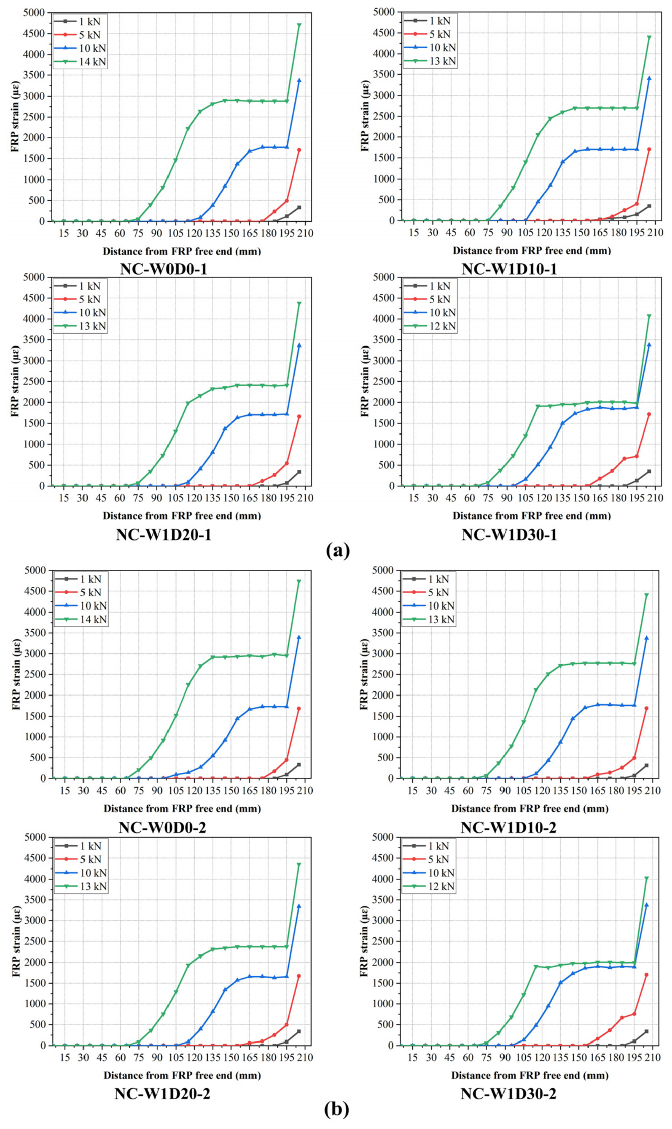
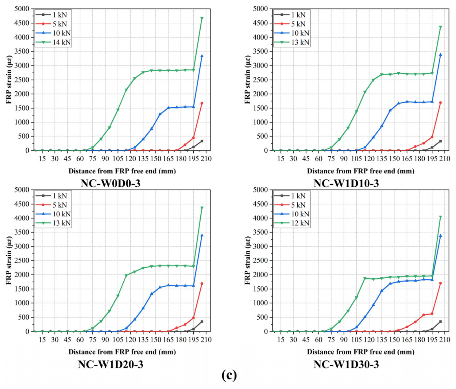
To further reveal the effect of crack depth on the load transfer process of the CFRP–concrete interface, the measured CFRP strain results were analyzed at single-side interfacial loads, Pi, of 1 kN, 5 kN, 10 kN, and near the ultimate state. Here, Pi denotes the nominal single-side interface load, which was taken as one-half of the total applied load, p, based on the approximate equal-load-sharing assumption for the two bonded sides. Near failure, Pi was therefore taken as approximately Pu/2, where Pu is the measured ultimate load of the specimen. Based on the strain data measured at distances of 5 mm, 15 mm, 25 mm, …, 195 mm, and 205 mm from the free end of the CFRP sheet, the strain distribution curves of the CFRP sheet along the bonded length under different load levels were plotted for specimens with different crack depths, as shown in Figure 7.
When Pi was 1 kN, the CFRP strain distributions of specimens with different notch depths showed only minor differences. The measured strain responses were mainly concentrated at gauge locations near the loaded end. At this relatively low load level, the effect of notch depth on the measured CFRP strain distribution was not pronounced.
When Pi was 5 kN, the overall CFRP strain levels of the specimens remained relatively close. However, specimens with deeper saw-cut notches generally exhibited larger strain responses at gauge locations farther toward the CFRP-free end. This result indicates that the notch depth affected the spatial distribution of interfacial load transfer.
When Pi was 10 kN, the differences in CFRP strain distribution among specimens with different notch depths became more evident. Specimens with deeper saw-cut notches generally exhibited larger strain responses at gauge locations farther toward the free end, indicating a more pronounced redistribution of the interfacial load-transfer field.
Near the ultimate state, appreciable CFRP strain responses were observed over a larger portion of the bonded region for all specimens. Because the ultimate loads differed among the specimens, the final curves in Figure 7 did not correspond to exactly the same Pi level and were used primarily to characterize the measured CFRP strain distributions near failure.
Overall, the CFRP strain was concentrated near the loaded end and decreased toward the free end. At the load levels of 5 and 10 kN, specimens with deeper saw-cut notches generally exhibited larger strain responses at gauge locations farther toward the free end, indicating that the interfacial load-transfer field was redistributed over a larger portion of the bonded region at an earlier load level. Geometrically, increasing the notch depth reduces the remaining concrete ligament beneath the notch and is therefore expected to decrease its local stiffness and restraint on the bonded CFRP. The reduced local restraint promotes earlier transfer of part of the interfacial load toward regions farther from the loaded end, which explains the observed development of CFRP strain toward the free end. Because the strain gauges were discretely arranged at 10 mm intervals and no predefined quantitative strain threshold was adopted, no characteristic strain-transfer length is assigned.

3.4. Effect of Saw-Cut Notch Depth on the Load-Relative Displacement Response

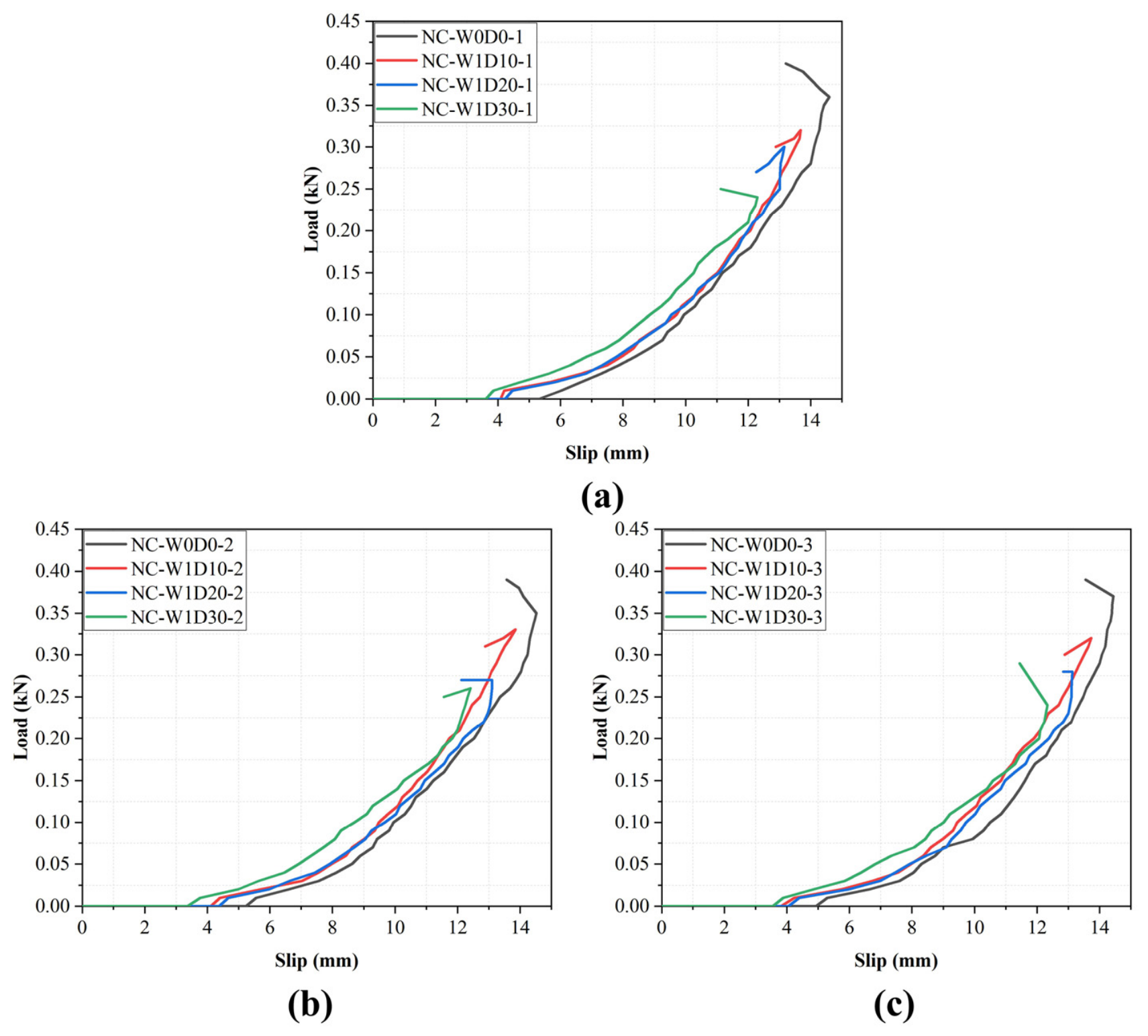
Figure 8 shows the curves of the relative displacement, Δw, between the concrete specimen and the steel loading head versus the single-side interfacial load, Pi, for specimens with different crack depths.
For all specimens, the measured system-relative displacement remained relatively small at low load and increased continuously and nonlinearly as the applied load approached the ultimate level. The repeated specimens within each notch-depth group exhibited consistent load–displacement trends.
With increasing notch depth, the specimens generally exhibited larger system-relative displacements at comparable load levels. Accordingly, a given displacement level was reached at a lower load as the notch depth increased. The mean ultimate system-relative displacement decreased from 0.360 mm for the unnotched group to 0.323, 0.283, and 0.247 mm for the groups with notch depths of 10, 20, and 30 mm, respectively.
The combination of larger system-relative displacement at comparable load levels and smaller terminal displacement with increasing notch depth indicates earlier compliance growth and earlier development of bond damage, rather than improved deformation capacity. As the remaining concrete ligament beneath the notch becomes smaller, its local stiffness and restraint are expected to decrease. Consequently, deformation and damage within the bonded region develop at a lower applied load, promoting earlier redistribution of interfacial bond shear stress and reducing the load- and system-relative displacement that can be sustained before cohesive debonding occurs.
The load–displacement behavior is therefore discussed as a continuous response rather than being divided into discrete stages with characteristic transition loads.

3.5. Effect of Saw-Cut Notch Depth on Interfacial Bond Shear Stress Distribution

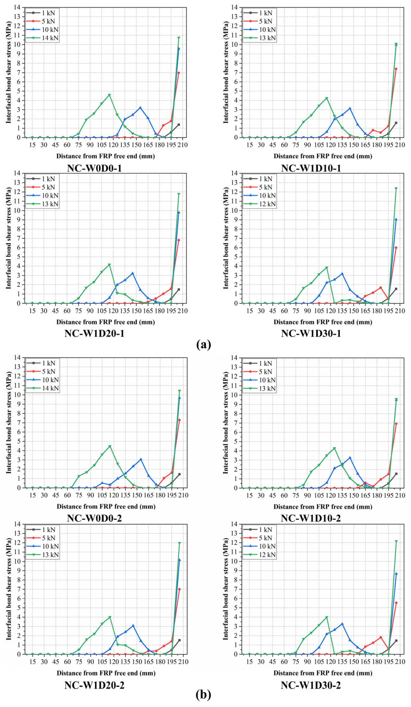
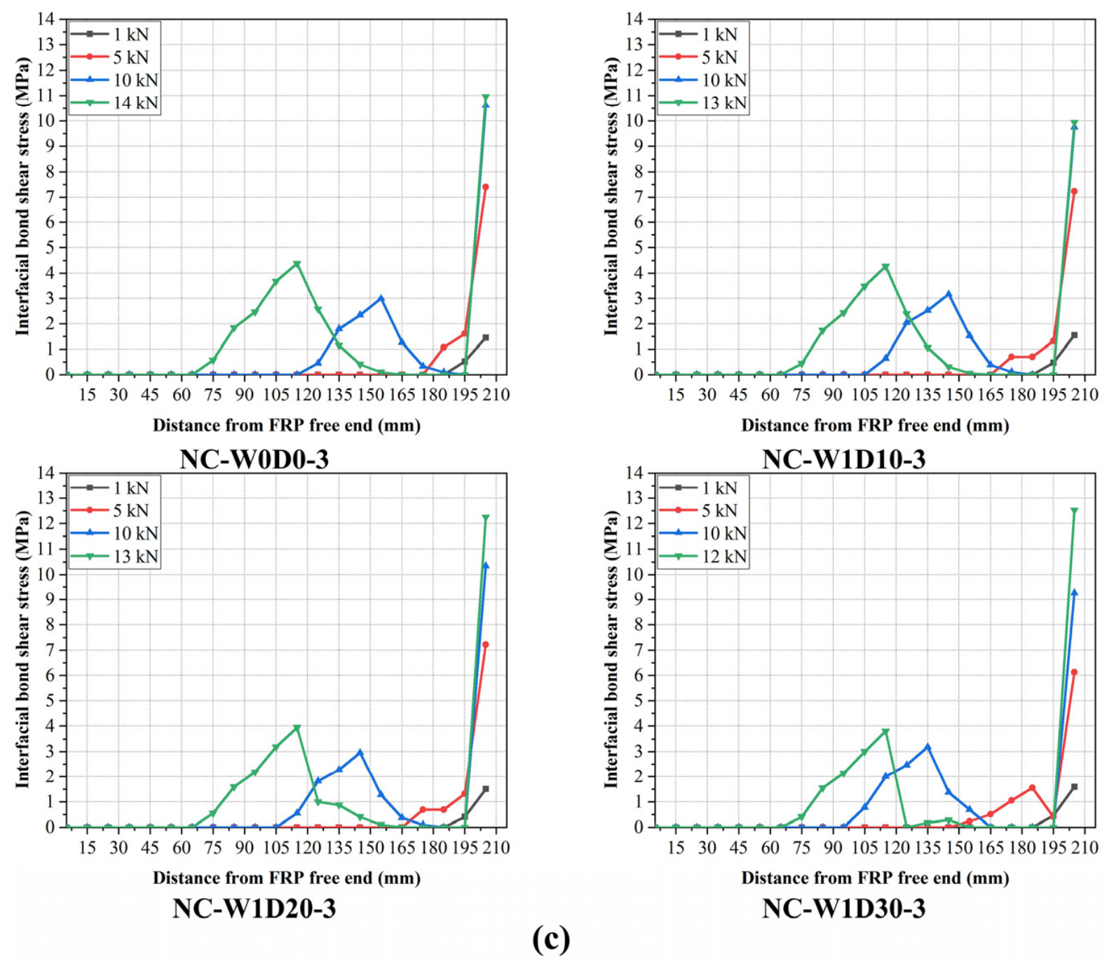
Figure 9 presents the segment-average interfacial bond shear stress distributions along the bonded length at different load levels. Two characteristic features were observed consistently among the repeated specimens. A high shear stress occurred near the CFRP-loaded end because of load introduction and the associated boundary effect, whereas an internal shear stress peak developed within the bonded region as the applied load increased. The migration of this internal peak provides a more representative indication of the advancement of the interfacial load-transfer front than the high value near the loaded end.
At 1 kN, the bond shear stress was mainly concentrated near the CFRP-loaded end, and the differences among the notch-depth groups were minor. At 5 kN, specimens with deeper saw-cut notches exhibited a broader nonzero shear stress region extending toward the CFRP-free end. At 10 kN, the effect of notch depth became more pronounced: the internal shear stress peak was located at approximately 155 mm from the CFRP-free end for the unnotched specimen, approximately 145 mm for the specimens with 10 and 20 mm deep notches, and approximately 135 mm for the specimen with a 30 mm deep notch. Near the ultimate state, stress concentration near the loaded end coexisted with an internal peak located at approximately 115 mm from the free end, indicating that the load-transfer field had developed over a relatively large portion of the bonded length.
These observations can be interpreted through the effect of the saw-cut notch on the remaining concrete ligament. Increasing the notch depth reduces the remaining ligament beneath the notch and is expected to decrease its local stiffness and its restraint on the bonded CFRP. The weakened local continuity causes part of the load introduced near the CFRP-loaded end to be redistributed earlier toward bonded regions farther from the loaded end. This mechanism explains both the larger CFRP strain responses observed farther toward the free end and the migration of the internal shear stress peak with increasing notch depth.
The same mechanism is also consistent with the load–displacement and failure results. Earlier redistribution and local compliance growth produced larger system-relative displacement at comparable load levels, while earlier accumulation of bond damage reduced the ultimate load and terminal system-relative displacement. All four notch-depth groups nevertheless exhibited near-surface concrete cohesive debonding, indicating that the saw-cut notch primarily altered the onset and spatial development of damage rather than changing the governing failure category. This redistribution mechanism also provides the physical basis for the notch-depth- and distance-dependent post-peak bond–slip responses discussed in Section 4.

4. Bond–Slip Behavior and Modeling of the CFRP–Concrete Interface Affected by Saw-Cut Notches

4.1. Normalized Bond–Slip Behavior and Development of the Curve-Shape Function

Based on the CFRP strain data collected from the 12 specimens during testing and the measured relative displacement between the concrete specimen and the steel loading head, the local interfacial bond shear stress and interfacial slip of the CFRP–concrete interface were calculated using Equations (1), (2), and (4). Accordingly, the experimental bond–slip curves of the interface under the influence of saw-cut notches were obtained.
Most existing bond–slip models have been established for interfaces without saw-cut notches and therefore do not account for the effects of notch depth and distance from the notch on the local bond response. Based on the normalized bond–slip curve form proposed by Lu [37], the saw-cut notch depth hk and the distance Li from the interfacial measurement point to the notch were introduced. Iterative trial calculations were conducted by comparing the calculated curves with the normalized experimental curves obtained from all 12 specimens. Based on the overall consistency of the curve trends and shapes, the coefficients a = 0.5, b = 0.5, and c = 5 were selected, resulting in the normalized curve-shape function given in Equation (5). Because the coefficients were not determined through pointwise residual minimization or a formal optimization-based regression procedure, Equation (5) is presented as an empirical normalized curve-shape function calibrated using the present experimental dataset.
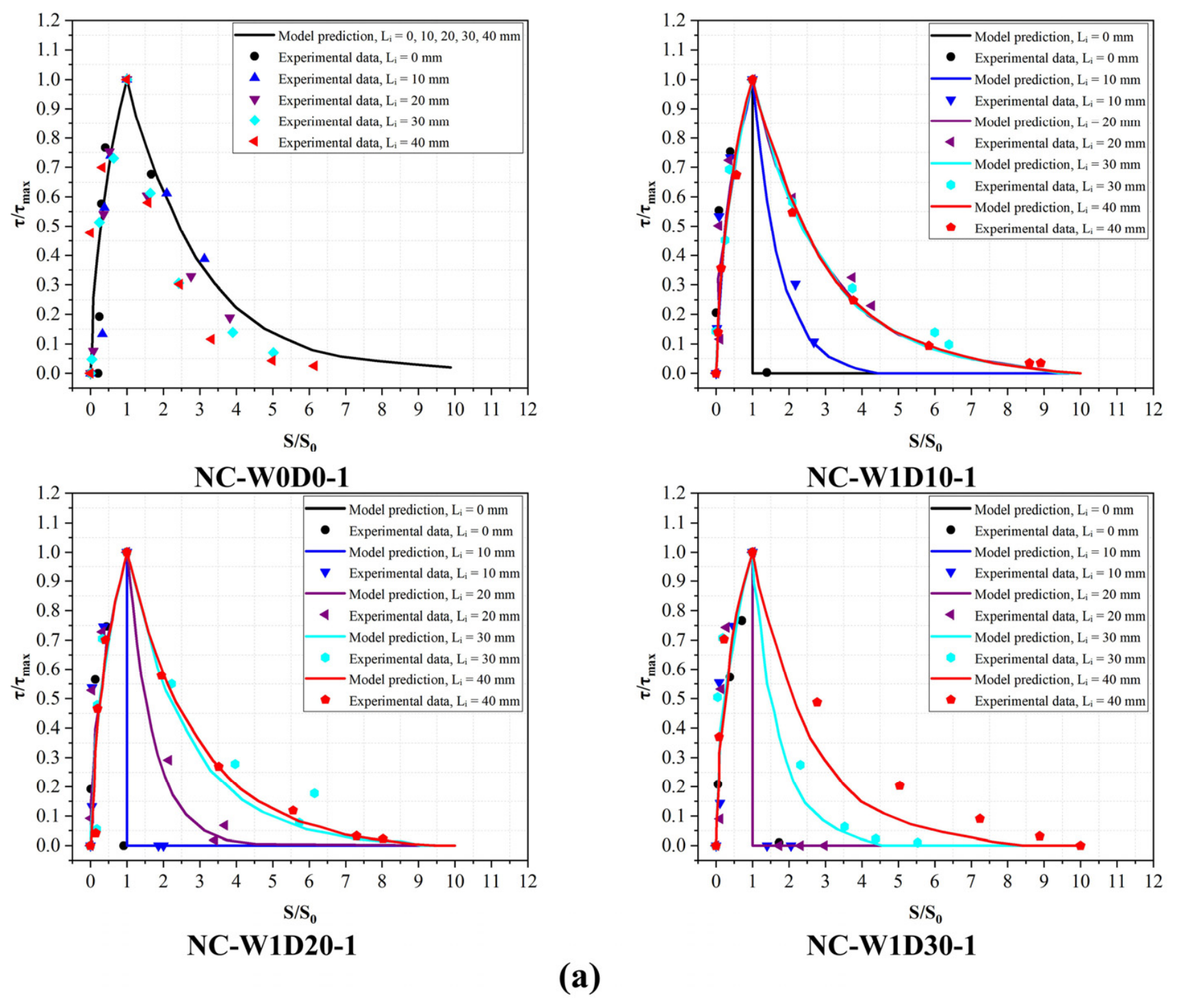
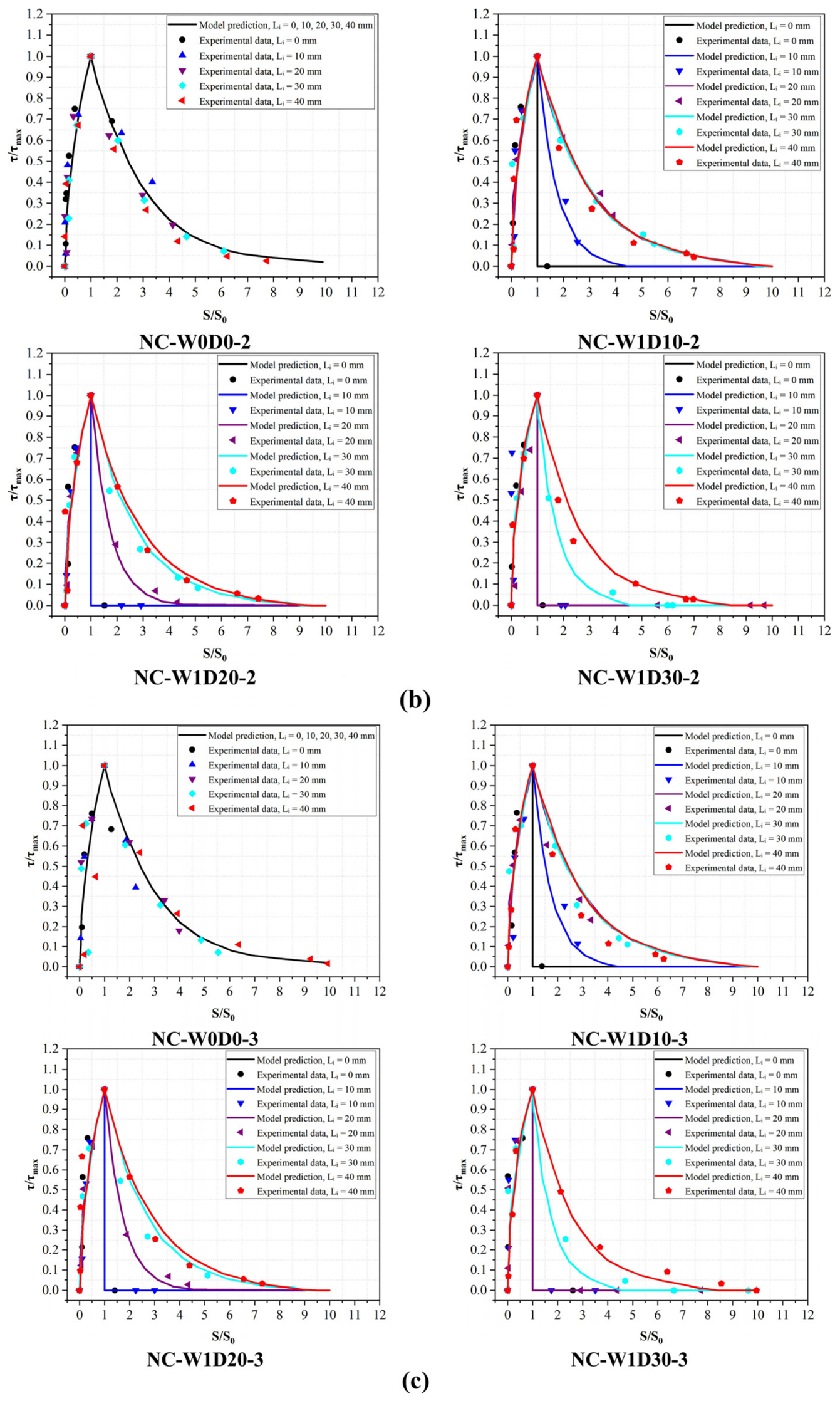
To compare the bond–slip curve shapes at different notch depths and Li positions, both the experimental and calculated curves were normalized. The normalized slip S/S0 was used as the horizontal coordinate, and the normalized bond shear stress τ/τmax was used as the vertical coordinate. Figure 10 presents an in-sample comparison of the experimental and calculated normalized curve shapes using the dataset adopted for parameter calibration.
As shown in Figure 10, the normalized bond–slip curves under different crack depths were mainly composed of a pre-peak ascending branch and a post-peak descending branch. When S/S0 was smaller than 1, the interfacial bond shear stress increased rapidly with increasing interfacial slip. When S/S0 reached 1, the interfacial bond shear stress reached its peak value, corresponding to τ/τmax of 1. When S/S0 was greater than 1, the curves entered the post-peak descending branch. Overall, the differences in the pre-peak ascending branch were relatively small under different crack depths and different Li positions, whereas the differences in the post-peak descending branch were significant. This indicates that the influence of saw-cut notches on the interfacial bond–slip relationship was mainly reflected in the post-peak softening stage.
For the specimens without saw-cut notches, namely NC-W0D0-1, NC-W0D0-2, and NC-W0D0-3, the experimental data at different Li positions were generally distributed around the same calculated curve, and the three repeated specimens showed good consistency. Since no saw-cut notch existed in these specimens, the variation in Li no longer represented an actual crack-position effect. Therefore, the differences among the normalized bond–slip curves at different measurement points were relatively small. After reaching the peak value, the curves decreased gradually. The post-peak descending branch was relatively gentle, and a certain residual bond stress was still maintained over a relatively large range of S/S0. This result indicates that, in the absence of saw-cut notches, the post-peak degradation of the CFRP–concrete interface was relatively slow, and the interface still retained a certain slip deformation capacity and residual bond capacity.
For the specimens with a crack depth of 10 mm, namely NC-W1D10-1, NC-W1D10-2, and NC-W1D10-3, the post-peak softening characteristics near the crack began to change significantly. When Li was 0 mm, the calculated curve dropped rapidly after reaching the peak value, and the experimental data also showed a rapid stress attenuation trend. This indicates that the post-peak bond capacity of the interface at the crack position degraded rapidly. When Li was 10 mm, the curve still showed a relatively rapid post-peak decrease, but the descending rate was lower than that at Li of 0 mm. When Li increased to 20 mm, 30 mm, and 40 mm, the post-peak descending branch gradually became gentler and progressively approached the curve shape of the specimens without saw-cut notches. This phenomenon indicates that, when the crack depth was 10 mm, the influence of the saw-cut notch on the interfacial bond–slip relationship was mainly concentrated near the crack, and this influence gradually weakened as the distance from the measurement point to the crack increased.
For the specimens with a crack depth of 20 mm, namely NC-W1D20-1, NC-W1D20-2, and NC-W1D20-3, the influence range of the crack further expanded. When Li was 0 mm and 10 mm, the curves both showed a rapid decrease after the peak, indicating obvious post-peak degradation in the interfacial region close to the crack. When Li was 20 mm, the curve showed a transitional characteristic. The post-peak descending rate was still relatively high, but the curve did not immediately attenuate to zero. When Li was 30 mm and 40 mm, the post-peak descending branch became obviously gentler and gradually approached the post-peak curve shape of the specimens without saw-cut notches. These results show that, with increasing crack depth, the interfacial region significantly affected by the saw-cut notch expanded outward from the crack position.
For the specimens with a crack depth of 30 mm, namely NC-W1D30-1, NC-W1D30-2, and NC-W1D30-3, the influence of the saw-cut notch on the interfacial bond–slip relationship was the most significant. When Li was 0 mm, 10 mm, and 20 mm, the calculated curves dropped rapidly after reaching the peak value, and the experimental data also showed relatively low post-peak residual bond stress. This indicates that post-peak softening was more pronounced at these positions. When Li was 30 mm, the curve exhibited an obvious transitional characteristic, and the post-peak descending rate was between those of the region near the crack and the region far from the crack. When Li was 40 mm, the post-peak descending branch became relatively gentle, and the overall curve shape was closer to the bond–slip relationship of the interface without saw-cut notches. This result further confirms that a greater crack depth leads to a larger influence range on the surrounding interfacial bond behavior.
Based on the three groups of repeated specimens shown in Figure 10, the calculated normalized curves generally reflect the main variation trends of the experimental normalized curves at different notch depths and Li positions within the present dataset. The comparison shows that the differences associated with notch depth and measurement-point position are mainly reflected in the post-peak descending branch. In particular, measurement points closer to the notch generally exhibited a steeper post-peak decrease and lower normalized residual bond stress, whereas the curves became gentler as the distance from the notch increased. This comparison is based on the dataset used for parameter calibration and does not constitute independent validation.
From the perspective of the crack-affected region, the influence of saw-cut notches on the interfacial bond–slip relationship did not disappear abruptly at a certain position. Instead, it exhibited an obvious spatial transition characteristic. According to the variation trends shown in Figure 10, the interfacial region near the crack can be approximately divided into a significantly affected region, a transition region, and a weakly affected region. The region close to the crack belongs to the significantly affected region, where the post-peak curve decreases rapidly and the residual bond capacity is relatively low. The region where the distance from the measurement point to the crack is approximately equal to the crack depth shows transitional characteristics, and the post-peak descending rate is between those of the region near the crack and the region far from the crack. When the distance from the measurement point to the crack further increases, the curve shape gradually approaches the bond–slip relationship of the interface without saw-cut notches. As the crack depth increased from 10 mm to 20 mm and 30 mm, both the significantly affected region and the transition region expanded away from the crack. This indicates that a greater crack depth leads to a larger influence range of the saw-cut notch on the local bond behavior of the CFRP–concrete interface.
In summary, the influence of saw-cut notches on the bond–slip relationship of the CFRP–concrete interface exhibits obvious spatial locality and depth dependence. The spatial locality is reflected by the fact that measurement points closer to the saw-cut notch show more pronounced post-peak softening and lower residual bond capacity. As the measurement point moves away from the saw-cut notch, the curve gradually recovers to a shape close to the bond–slip relationship of the interface without saw-cut notches. The depth dependence is reflected by the fact that a greater crack depth leads to a larger affected interfacial region and a wider post-peak degradation zone. These results indicate that saw-cut notches not only change the post-peak bond behavior of the local interface near the crack, but also affect the bond–slip evolution of the CFRP–concrete interface within a certain surrounding range.
Z = S / S 0 L i , e f f = m a x L i , Δ x 2 ,   Δ x = 10 mm τ / τ max = Z 0.5 ,   0 Z 1 τ / τ max = e 0.5 ( Z 1 ) ,   Z > 1 , h k = 0 τ / τ max = e 0.5 Z 1 e h k / L i , e f f 5 ,   Z > 1 , h k > 0
where Z denotes the normalized interfacial slip; S denotes the interfacial slip; S0 denotes the interfacial slip corresponding to the maximum interfacial bond shear stress; Li,eff denotes the effective distance used in Equation (5); Li denotes the nominal distance from measurement location i on the interface to the centerline of the saw-cut notch; Δx denotes the spacing between adjacent strain gauges, taken as 10 mm in this study; τ denotes the interfacial bond shear stress of the CFRP–concrete interface; τmax denotes the maximum interfacial bond shear stress; and hk denotes the saw-cut notch depth. Because the measured peak bond stress τmax and its corresponding slip S0 are used for normalization, Equation (5) describes the normalized curve shape rather than independently predicting a complete dimensional bond–slip relationship. The function does not independently determine the dimensional values of τmax and S0, which must be obtained from experimental measurements or from an independently established dimensional model.
The saw-cut notches in this study were artificially introduced to obtain a controllable and repeatable crack geometry, thereby isolating the effect of crack depth on the CFRP–concrete interfacial bond behavior. Such controlled cracks can be regarded as simplified representations of cracks in existing concrete structures. In actual structures, natural cracks may exhibit irregular paths, rough fracture surfaces, aggregate interlock, and residual contact between crack faces, which may influence local stress concentration, residual load transfer, and post-peak bond degradation near the crack. Therefore, the results and the proposed bond–slip model should be interpreted within the tested range of artificial saw-cut notches, namely a crack width of 1 mm and crack depths of 0–30 mm. The applicability of the model to naturally cracked concrete substrates and other crack widths requires further verification. The comparison presented in Figure 10 is based on the dataset used for parameter calibration. The broader applicability of the normalized curve-shape function should be evaluated using independent experimental datasets without recalibrating the coefficients a, b, and c.

4.2. Comparison with Established Models and Implications for Effective Bond Length and Anchorage Design

The present results can be compared with established bond models for intact concrete substrates and previous studies of cracked or notched substrates. The normalized bond–slip curve form proposed by Lu et al. [37] provides a reference response for conventional FRP-to-concrete bonded interfaces without a predefined transverse discontinuity. Consistent with this intact-substrate framework, the unnotched specimens in the present study exhibited relatively gradual post-peak softening and comparatively small spatial differences among the normalized curves obtained at different measurement positions. By contrast, the notched specimens exhibited steeper post-peak degradation near the notch, lower residual bond capacity, and an affected region that expanded with increasing notch depth. Thus, the intact-substrate model provides a useful baseline but does not explicitly represent the depth-dependent and spatially localized degradation caused by a transverse saw-cut notch.
The observed response is qualitatively consistent with previous investigations of cracked or notched concrete substrates. Mohammadi et al. [32] showed that existing cracks in notched beams could initiate intermediate-crack debonding. Dai et al. [33] investigated mixed-mode interfacial peeling in FRP-bonded notched beams, and Zheng et al. [33] coupled Mode II interfacial debonding with Mode I concrete crack propagation in an analytical framework. These studies demonstrated that cracks or notches modify the local stress state and debonding process. However, their beam-type responses were influenced by member flexure, concrete crack development, and mixed-mode loading. The present double-shear tests complement these studies by showing, under a predominantly shear-transfer condition, that increasing saw-cut notch depth promotes earlier redistribution of CFRP strain and interfacial bond shear stress and enlarges the region of rapid post-peak bond degradation.
For the intact substrate, the effective bond length calculated using the Chen and Teng model [44] was 97.8 mm, whereas the adopted bonded length was 200 mm. The saw-cut notch was located 95 mm from the CFRP-loaded end, approximately within the principal load-transfer region indicated by the intact-substrate effective-bond-length calculation. Although the total bonded length exceeded the calculated effective bond length, the ultimate load and ultimate system-relative displacement decreased as the notch depth increased. Therefore, satisfying an effective-bond-length requirement established for an intact substrate does not, by itself, prevent local bond degradation when a discontinuity intersects the principal load-transfer region.
These results suggest that anchorage design for CFRP strengthening of cracked concrete should consider the condition of the bonded substrate in addition to the total bonded length. In particular, the depth and position of a crack relative to the expected load-transfer region should be evaluated, and sufficient continuous sound bonded length should be provided beyond the crack in the load-transfer direction. Where necessary, local strengthening, confinement, or supplementary anchorage may be considered. In the present tests, no anchorage-slip failure was observed, whereas all specimen groups exhibited near-surface concrete cohesive debonding. This indicates that preventing end-anchorage slip does not necessarily eliminate substrate-controlled debonding within a cracked or notched bonded region. Because bonded length and anchorage configuration were not varied systematically, the present results do not provide a revised effective-bond-length equation or a quantitative anchorage design model for cracked substrates.

5. Conclusions

Within the experimental range considered in this study, namely a fixed saw-cut notch width of 1 mm and crack depths of 0, 10, 20, and 30 mm, the influence of saw-cut notch depth on the bond behavior of the CFRP–concrete interface was investigated through double-shear tests. The variations in the ultimate bearing capacity, CFRP strain transfer, load-relative displacement relationship, interfacial bond shear stress distribution, and interfacial bond–slip relationship were analyzed. An empirical normalized curve-shape function considering saw-cut notch depth and distance from the notch was also developed.
(1)
Under the fixed saw-cut notch width of 1 mm, increasing saw-cut notch depth reduced both the bearing capacity and deformation capacity of the CFRP–concrete interface, but the influence on deformation capacity was more pronounced. When the crack depth increased from 0 mm to 10 mm, 20 mm, and 30 mm, the average ultimate load decreased by approximately 5.0%, 9.2%, and 14.7%, whereas the ultimate relative displacement decreased by approximately 10.2%, 21.3%, and 31.5%. For the 30 mm crack depth, the reduction in ultimate relative displacement was about 2.14 times that of the ultimate load, indicating that saw-cut notches had a stronger effect on interfacial deformation capacity than on strength.
(2)
Increasing the saw-cut notch depth altered the spatial distribution of the measured CFRP strain. At the same nominal single-side interface load, specimens with deeper notches generally exhibited larger strain responses at gauge locations farther toward the CFRP-free end, indicating redistribution of the interfacial load-transfer field toward locations farther from the loaded end. Meanwhile, the mean ultimate system-relative displacement decreased with increasing notch depth, demonstrating a reduction in the deformation capacity of the bonded interface.
(3)
The interfacial bond shear stress distribution showed clear load-stage dependence. At the low load stage, the shear stress was mainly concentrated near the CFRP-loaded end. At Pi of 10 kN, the internal shear stress peak moved from approximately 155 mm from the CFRP-free end in the uncracked specimen to approximately 135 mm in the specimen with a 30 mm crack depth. This indicates that increasing crack depth promoted the earlier advancement of the interfacial shear stress transfer front toward the CFRP-free end.
(4)
Based on the normalized bond–slip curve form proposed by Lu [37], an empirical normalized curve-shape function was developed by introducing the saw-cut notch depth and the distance from the interfacial measurement point to the notch. Within the present dataset, the experimental and calculated normalized curves showed similar overall trends. The effect of the notch was mainly reflected in the post-peak descending branch: measurement points closer to the notch generally exhibited a steeper decrease and lower normalized residual bond stress. Because the function uses the measured τmax and S0, its dimensional application requires these parameters to be supplied independently.
(5)
Within the tested range of artificial saw-cut notches, the influence of saw-cut notches on the bond–slip relationship of the CFRP–concrete interface exhibited spatial locality and depth dependence. As the crack depth increased, the affected interfacial region gradually expanded. Therefore, in the CFRP strengthening design of existing cracked concrete structures, the crack depth and local interfacial bond degradation near the crack should be considered. The effects of crack width and naturally formed cracks require further investigation.

Author Contributions

Conceptualization, B.Y. and H.J.; methodology, B.Y. and J.W.; software, Z.L. and J.L.; validation, Z.L., F.M.; formal analysis, Z.L. and F.M.; investigation, F.M.; resources, J.X.; data curation, Z.L.; writing—original draft preparation, F.M. and Z.L.; writing—review and editing, F.M. and Z.L.; visualization, J.W.; supervision, J.L. and J.X.; project administration, B.Y.; funding acquisition, H.J. All authors have read and agreed to the published version of the manuscript.

Funding

The research presented was funded by the National Natural Science Foundation of China (No. 51778150 and No. 52278160).

Data Availability Statement

The original contributions presented in the study are included in the article; further inquiries can be directed to the corresponding author.

Conflicts of Interest

The authors declare no conflicts of interest.

References

  1. Diaferio, M.; Varona, F.B. Concrete structures: Latest advances and prospects for a sustainable future. Appl. Sci. 2024, 14, 3803. [Google Scholar] [CrossRef]
  2. Jiang, H.B.; Lai, Z.W.; Chen, Z.Q.; Cao, Z.P.; Xiao, J.; Zhang, S.F.; Zhang, W.L.; Chen, M.Z. Interfacial shear behaviors of transverse PBL connectors deeply embedded in steel-UHPC joints. Constr. Build. Mater. 2026, 534, 146856. [Google Scholar] [CrossRef]
  3. Li, C.; Li, J.; Ren, Q.; Zheng, Q.; Jiang, Z. Durability of concrete coupled with life cycle assessment: Review and perspective. Cem. Concr. Compos. 2023, 139, 105041. [Google Scholar] [CrossRef]
  4. Jiang, H.B.; Wu, K.S.; Shen, R.Y.; Li, B.X.; Xiao, J.; Mo, F.; Tian, Y.Q. Interfacial shear behavior between precast UHPC girder and cast-in-place NC slab with large groove and rebars. Structures 2026, 85, 111041. [Google Scholar] [CrossRef]
  5. Xiao, J.; Liu, J.J.; Liang, R.Q.; Liu, L.F.; Feng, J.H.; He, Z.X.; Chen, X.Y.; Jiang, H.B. Durability assessment of UHPC with varying steel fiber contents under sulfuric acid attack: Macro-Micro characterization. Eng. Fail. Anal. 2026, 186, 110523. [Google Scholar] [CrossRef]
  6. Feng, R.; Li, W.; Quach, W.-M.; Zeng, J.-J. Axial compressive performance of FRP-strengthened reinforced concrete columns in corrosive environment. Eng. Struct. 2026, 360, 122819. [Google Scholar] [CrossRef]
  7. Naser, M.Z.; Hawileh, R.A.; Abdalla, J.A. Fiber-reinforced polymer composites in strengthening reinforced concrete structures: A critical review. Eng. Struct. 2019, 198, 109542. [Google Scholar] [CrossRef]
  8. El-Sayed, A.K.; Al-Zaid, R.A.; Al-Negheimish, A.I.; Shuraim, A.B.; Alhozaimy, A.M. Long-term behavior of wide shallow RC beams strengthened with externally bonded CFRP plates. Constr. Build. Mater. 2014, 51, 473–483. [Google Scholar] [CrossRef]
  9. Aljidda, O.; Alnahhal, W.; El Refai, A. Influence of cut-out openings on the flexural behavior of one-way concrete slabs strengthened with NSM-FRP bars and EB-CFRP strips. Structures 2025, 79, 109547. [Google Scholar] [CrossRef]
  10. Lal, M.; Chidambaram, R.S. Flexural strengthening of RC beams with glass fiber textile reinforced concrete and hybrid anchorage technique. Constr. Build. Mater. 2025, 505, 144615. [Google Scholar] [CrossRef]
  11. Bai, Y.-L.; Niu, W.-Q.; Xie, W.-J. Flexural behavior of reinforced concrete beams strengthened with hybrid carbon-PET FRP laminates. Constr. Build. Mater. 2024, 411, 134372. [Google Scholar] [CrossRef]
  12. Mansouri, S.; Rahai, A.; Hosseinnia, A. Performance evaluation of FRP-strengthened self-compacting concrete filled double-steel-plate composite shear walls: Experimental and numerical studies. Structures 2025, 81, 110174. [Google Scholar] [CrossRef]
  13. Kabashi, N.; Muhaxheri, M.; Krasniqi, E. Advancements in Fiber-Reinforced Polymer (FRP) retrofitting techniques for seismic resilience of reinforced concrete structures. Buildings 2025, 15, 587. [Google Scholar] [CrossRef]
  14. Nguyen, M.H.; Ho, M.H.; Tran, V.R. Flexural performance of reinforced concrete beams strengthened with prestressed FRP sheets: Experiments and numerical investigations. Case Stud. Constr. Mater. 2024, 21, e03475. [Google Scholar] [CrossRef]
  15. Malla, P.; Dolati, S.S.K.; Ortiz, J.D.; Mehrabi, A.; Nanni, A. Damage and defects in fiber-reinforced polymer reinforced and strengthened concrete elements. J. Compos. Constr. 2023, 27, 04023017. [Google Scholar] [CrossRef]
  16. Meier, U.; Erica, M.A. Advantages of composite materials in the post-strengthening technique for developing countries. In Proceedings of the 6th International Colloquium on Concrete in Developing Countries, Lahore, Pakistan, 4–6 January 1997; pp. 1–11. [Google Scholar]
  17. Al-Zu’bi, M.; Fan, M.Z.; Anguilano, L. Advances in bonding agents for retrofitting concrete structures with fibre reinforced polymer materials: A review. Constr. Build. Mater. 2022, 330, 127115. [Google Scholar] [CrossRef]
  18. Aram, M.R.; Czaderski, C.; Motavalli, M. Debonding failure modes of flexural FRP-strengthened RC beams. Compos. Part B Eng. 2008, 39, 826–841. [Google Scholar] [CrossRef]
  19. Gunes, O.; Buyukozturk, O.; Karaca, E. A fracture-based model for FRP debonding in strengthened beams. Eng. Fract. Mech. 2009, 76, 1897–1909. [Google Scholar] [CrossRef]
  20. Shi, H.; Guo, J.; Xia, Z. Detection of interfacial bonding defects in FRP-strengthened concrete using thermal deformation analysis and DIC. Case Stud. Constr. Mater. 2025, 23, e05471. [Google Scholar] [CrossRef]
  21. Mensah, C.; Wang, Z.; Bonsu, A.O.; Liang, W. Effect of different bond parameters on the mechanical properties of FRP and concrete interface. Polymers 2020, 12, 2466. [Google Scholar] [CrossRef] [PubMed]
  22. Li, P.-D.; Zhao, Y.; Wu, Y.-F.; Lin, J.-P. Effect of defects in adhesive layer on the interfacial bond behaviors of externally bonded CFRP-to-concrete joints. Eng. Struct. 2023, 278, 115495. [Google Scholar] [CrossRef]
  23. Min, X.; Yang, D.; Song, S.; Li, X. Study on the stress threshold of preventing interfacial fatigue debonding in concrete beams strengthened with externally-bonded FRP laminates. Buildings 2024, 14, 430. [Google Scholar] [CrossRef]
  24. Pohoryles, D.A.; Melo, J.; Rossetto, T. Combined flexural and shear strengthening of RC T-beams with FRP and TRM: Experimental study and parametric finite element analyses. Buildings 2021, 11, 520. [Google Scholar] [CrossRef]
  25. Zhang, Y.; Li, N.; Wang, Q.; Li, Z.; Qin, X. Shear behavior of T-shaped concrete beams reinforced with FRP. Buildings 2022, 12, 2062. [Google Scholar] [CrossRef]
  26. Askar, M.K.; Hassan, A.F.; Al-Kamaki, Y.S.S. Flexural and shear strengthening of reinforced concrete beams using FRP composites: A state of the art. Case Stud. Constr. Mater. 2022, 17, e01189. [Google Scholar] [CrossRef]
  27. Yao, J.; Teng, J.G.; Chen, J.F. Experimental study on FRP-to-concrete bonded joints. Compos. Part B Eng. 2005, 36, 99–113. [Google Scholar] [CrossRef]
  28. De Lorenzis, L.; Miller, B.; Nanni, A. Bond of fiber-reinforced polymer laminates to concrete. ACI Mater. J. 2001, 98, 256–264. [Google Scholar] [CrossRef] [PubMed]
  29. Chen, J.-F.; Yang, Z.J.; Holt, G. FRP or steel plate-to-concrete bonded joints: Effect of test methods on experimental bond strength. Steel Compos. Struct. 2001, 1, 231–244. [Google Scholar] [CrossRef]
  30. Wang, Y.; Huang, C.; Guo, X. Study on the influence of end anchoring on CFRP-concrete interface through double-lap shear testing. Structures 2024, 69, 107457. [Google Scholar] [CrossRef]
  31. Ferrier, E.; Gagnon, A.; Le Roy, C. Durability of FRP-to-concrete bonded joints subjected to accelerated ageing in laboratory and to field natural ageing. Constr. Build. Mater. 2026, 535, 146975. [Google Scholar] [CrossRef]
  32. Mohammadi, T.; Wan, B.; Harries, K.A.; Sweriduk, M.E. Bond behavior of FRP–concrete in presence of intermediate crack debonding failure. J. Compos. Constr. 2017, 21, 04017018. [Google Scholar] [CrossRef]
  33. Dai, J.G.; Ueda, T.; Sato, Y. Bonding characteristics of fiber-reinforced polymer sheet–concrete interfaces under dowel load. J. Compos. Constr. 2007, 11, 138–148. [Google Scholar] [CrossRef]
  34. Zheng, J.J.; Dai, J.G.; Fan, X.L. Fracture analysis of FRP-plated notched concrete beams subjected to three-point bending. J. Eng. Mech. 2016, 142, 04015096. [Google Scholar] [CrossRef]
  35. Biscaia, H.C.; Chastre, C.; Silva, M.A.G. A simple method for the determination of the bond-slip model of artificially aged joints. J. Compos. Constr. 2019, 23, 04019028. [Google Scholar] [CrossRef]
  36. Lv, H.D.; Xie, W.J.; Gao, W.Y. Nonlinear bond-slip model for fiber-reinforced polymer laminates externally bonded to thermally damaged concrete. Adv. Struct. Eng. 2024, 27, 585–605. [Google Scholar] [CrossRef]
  37. Lu, X.Z.; Teng, J.G.; Ye, L.P.; Jiang, J.J. Bond-slip models for FRP sheets/plates bonded to concrete. Eng. Struct. 2005, 27, 920–937. [Google Scholar] [CrossRef]
  38. GB/T 50081-2019; Standard for Test Methods of Concrete Physical and Mechanical Properties. China Architecture & Building Press: Beijing, China, 2019.
  39. GB50728-2011; Technical Code for Safety Appraisal of Engineering Structural Strengthening Materials. China Architecture & Building Press: Beijing, China, 2011.
  40. Han, Q. Research on Bond-Slip Mechanism Between CFRP and Concrete Interface. Ph.D. Thesis, South China University of Technology, Guangzhou, China, 2011. [Google Scholar]
  41. Zheng, X. Research on Bond-Slip Mechanism Between CFL and Concrete Interface in Hygrothermal Environment. Ph.D. Thesis, South China University of Technology, Guangzhou, China, 2014. [Google Scholar]
  42. Ferracuti, B.; Savoia, M.; Mazzotti, C. Interface law for FRP-concrete delamination. Compos. Struct. 2007, 80, 523–531. [Google Scholar] [CrossRef]
  43. Biscaia, H.C.; Chastre, C.; Silva, M.A.G. Nonlinear numerical analysis of the debonding failure process of FRP-to-concrete interfaces. Compos. Part B Eng. 2013, 50, 210–223. [Google Scholar] [CrossRef]
  44. Chen, J.; Teng, J.G. Anchorage strength models for FRP and steel plates attached to concrete. J. Struct. Eng. 2001, 127, 784–791. [Google Scholar] [CrossRef]
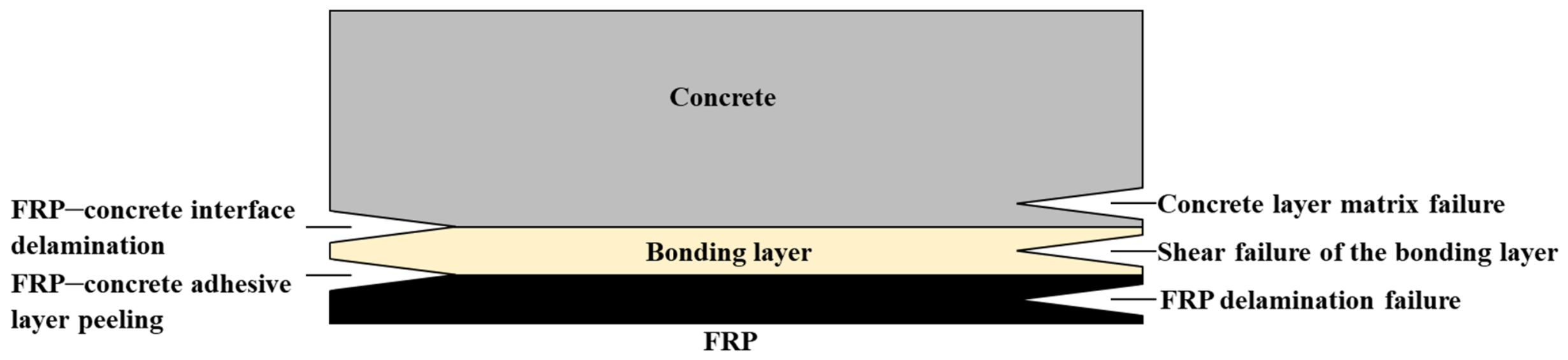
Figure 1. FRP–concrete interface failure modes.
Buildings 16 03111 g001
Figure 2. FRP–concrete testing methods. (a) beam test; (b) modified beam test; (c) single-shear test; (d) double-shear test.
Buildings 16 03111 g002
Figure 3. Schematic diagram of double-shear loading test.
Buildings 16 03111 g003
Figure 4. Specimen size (mm): (a) elevation view; (b) side view; (c) bottom view.
Buildings 16 03111 g004
Figure 5. Specimen preparation process: (a) formwork fabrication and concrete casting; (b) demolding after curing; (c) fabrication of artificial saw-cut notches; (d) CFRP sheet bonding and end anchorage.
Buildings 16 03111 g005
Figure 6. Representative debonding failure of the CFRP–concrete interface.
Buildings 16 03111 g006
Figure 7. CFRP strain distributions versus distance from the CFRP-free end for specimens with different saw-cut notch depths under different load levels: (a) first group; (b) second group; (c) third group.
Buildings 16 03111 g007aBuildings 16 03111 g007b
Figure 8. Load-relative displacement curves between the concrete specimen and the steel loading head for specimens with different saw-cut notch depths: (a) first group; (b) second group; (c) third group.
Buildings 16 03111 g008
Figure 9. Interfacial bond shear stress distributions versus distance from the CFRP-free end for specimens with different saw-cut notch depths under different load levels: (a) first group; (b) second group; (c) third group.
Buildings 16 03111 g009aBuildings 16 03111 g009b
Figure 10. Comparison of experimental and calculated normalized bond–slip curve shapes at different saw-cut notch depths and Li positions: (a) first group; (b) second group; (c) third group.
Buildings 16 03111 g010aBuildings 16 03111 g010b
Table 1. Specimen matrix with different experimental parameters.
SpecimenConcrete TypeCrack Width (mm)Crack Depth (mm)
NC-W0D0-1NC00
NC-W0D0-2NC00
NC-W0D0-3NC00
NC-W1D10-1NC110
NC-W1D10-2NC110
NC-W1D10-3NC110
NC-W1D20-1NC120
NC-W1D20-2NC120
NC-W1D20-3NC120
NC-W1D30-1NC130
NC-W1D30-2NC130
NC-W1D30-3NC130
Table 2. Mix proportions of concrete (Unit: kg/m3).
Concrete TypeCementWaterFine AggregateCoarse Aggregate
NC4662055871192
Table 3. Mechanical properties of CFRP.
FRP TypeCharacteristic Tensile StrengthTensile Elastic ModulusElongation at BreakFlexural StrengthInterlaminar Shear StrengthPull-Off Bond Strength Between CFRP Composite and Substrate
UT70-303920 MPa237 GPa1.71%745 MPa47.7 MPa3.21 MPa
Table 4. Governing failure modes of the tested specimens.
SpecimensSaw-Cut Notch Depth (mm)Governing Failure Mode
NC-W0D0-1, NC-W0D0-2, NC-W0D0-30Near-surface concrete cohesive debonding
NC-W1D10-1, NC-W1D10-2, NC-W1D10-310Near-surface concrete cohesive debonding
NC-W1D20-1, NC-W1D20-2, NC-W1D20-320Near-surface concrete cohesive debonding
NC-W1D30-1, NC-W1D30-2, NC-W1D30-330Near-surface concrete cohesive debonding
Table 5. Test results of specimens with different saw-cut notch depths.
SpecimenSaw-Cut Notch Depth (mm)Ultimate Bearing Capacity (kN)Ultimate Relative Displacement (mm)
NC-W0D0-1029.200.36
NC-W0D0-2029.050.35
NC-W0D0-3028.650.37
NC-W1D10-11027.220.32
NC-W1D10-21027.830.33
NC-W1D10-31027.480.32
NC-W1D20-12026.450.30
NC-W1D20-22026.220.27
NC-W1D20-32026.270.28
NC-W1D30-13024.630.24
NC-W1D30-23024.820.26
NC-W1D30-33024.660.24
Table 6. Statistical analysis of ultimate load for specimens with different notch depths.
Notch Depth
(mm)
Mean Load
(kN)
SD
(kN)
COV
(%)
Load Reduction
(%)
95% CI
(kN)
Holm-Adjusted p
vs. 0 mm
028.970.280.98028.260–29.673-
1027.510.311.115.026.750–28.2700.0039
2026.310.120.469.226.013–26.6140.0023
3024.700.100.4114.724.450–24.9570.0014
Note: Values are based on n = 3 specimens per group. CI denotes the two-sided 95% confidence interval. Adjusted p values were obtained from pairwise Welch’s t-tests against the unnotched group using the Holm procedure. One-way ANOVA: F(3,8) = 196.59, p < 0.001.
Table 7. Statistical analysis of ultimate system-relative displacement for specimens with different notch depths.
Notch Depth
(mm)
Mean Displacement
(mm)
SD
(mm)
COV
(%)
Displacement Reduction
(%)
95% CI
(mm)
Holm-Adjusted p
vs. 0 mm
00.3600.0102.7800.335–0.385-
100.3230.0061.7910.20.309–0.3380.0100
200.2830.0155.3921.30.245–0.3210.0066
300.2470.0124.6831.50.218–0.2750.0007
Note: Values are based on n = 3 specimens per group. CI denotes the two-sided 95% confidence interval. Adjusted p values were obtained from pairwise Welch’s t-tests against the unnotched group using the Holm procedure. One-way ANOVA: F(3,8) = 57.78, p < 0.001.
Disclaimer/Publisher’s Note: The statements, opinions and data contained in all publications are solely those of the individual author(s) and contributor(s) and not of MDPI and/or the editor(s). MDPI and/or the editor(s) disclaim responsibility for any injury to people or property resulting from any ideas, methods, instructions or products referred to in the content.