1. Introduction
In the face of global warming, a low-carbon transition through emission reduction has become a global consensus [
1]. The construction industry stands as a major consumer of energy and a primary source of carbon emissions, accounting for approximately 30% of the global total [
2]. The global push towards climate neutrality has prompted leading nations to adopt distinct but overlapping approaches to net-zero carbon buildings [
3]. In the UK, frameworks driven by organizations like the UK Green Building Council emphasize immediate action on both operational energy use and embodied carbon through stringent whole-life carbon assessments. The United States focuses on integrating passive envelope designs and active renewable energy systems to offset greenhouse gas emissions.
In recent years, as carbon emissions during the operational phase of buildings have been gradually controlled and mitigated, the proportion of embodied carbon of buildings has steadily risen, positioning it as a core target for low-carbon design [
4,
5]. Particularly during the materialization stage of construction, material production is typically the dominant contributor to embodied carbon emissions [
6]. Consequently, optimizing structural efficiency to reduce material demand represents one of the critical pathways to lowering the embodied carbon emissions of landscape structures [
7,
8,
9].
Topology optimization (TO), as a performance-driven structural design method, can identify the core load-bearing paths within a given set of loads, constraints, and design domains [
10,
11]. By redistributing material logically, it achieves the lightweight design of structures. However, in current architectural and landscape engineering practices, the outputs of topology optimization often feature free-form surfaces, complex joints, and non-standard components. These characteristics make it difficult to directly translate optimization results into physical structures that satisfy conventional manufacturing and on-site assembly requirements [
12,
13]. Therefore, bridging the gap between the scientific load-bearing logic of topology optimization and its practical constructability has emerged as a critical challenge.
Design for Manufacture and Assembly (DfMA) is an engineering methodology that integrates manufacturing capabilities and construction logic into the early design phase to minimize component complexity, reduce material waste, and improve assembly efficiency [
14]. Currently, this method has been integrated into the Modern Methods of Construction (MMC) framework by the Royal Institute of British Architects (RIBA), serving as an important tool to promote standardization and modularization [
15,
16]. Existing research demonstrates that DfMA is highly effective in reducing construction complexity, minimizing material waste, and shortening on-site assembly schedules [
17,
18,
19]. Nevertheless, regarding the complex forms generated by topology optimization, how DfMA can systematically guide their morphological simplification and further intervene in their life-cycle carbon emission evaluation remains an area requiring exploration.
To address the widespread material redundancy found in landscape structures and the practical challenges of implementing topology optimization results, this study introduces the DfMA method to reduce the geometric complexity of optimized structures, thereby lowering the embodied carbon emissions. Focusing on three typical landscape facilities—landscape benches, pavilions, and bridges—this study employs DfMA principles to simplify complex topological forms into standardized, modular, and assemblable structure systems. On this basis, the research compares the life-cycle embodied carbon emissions among the initial, topology-optimized, and DfMA-simplified designs. This approach aims to reveal the value of a synergistic topology optimization–DfMA strategy in achieving lightweight structures, enhancing constructability, and driving low-carbon design.
While previous studies have explored topology optimization for material reduction and DfMA for assembly efficiency, there remains a gap in synergizing these approaches to address the constructability of topology-optimized structures and their subsequent life-cycle carbon impacts. This study advances the current state of knowledge by proposing an integrated topology optimization–DfMA framework. By simplifying free-form topological outputs into standard, DfMA-compliant modules, this study provides a new pathway to evaluate and achieve low-carbon structural design.
2. Literature Review
Embodied carbon emissions generally refer to the greenhouse gas emissions associated with buildings and structures throughout their life cycles, excluding the operational phase. This encompasses all stages, including raw material extraction, material production, logistics and transportation, construction, routine maintenance, and demolition and disposal [
20]. Among these, the material production phase is typically the primary source of embodied carbon [
11]. Therefore, reducing material consumption can simultaneously lower carbon emissions across transportation, processing, and waste disposal. Within the overall landscape structure, structural components typically account for the majority of embodied carbon [
21], with emission levels closely tied to total material consumption, component morphology, and structural load-bearing efficiency [
22]. Consequently, performance-driven structural design methods, such as topology optimization, can reduce embodied carbon emissions through lightweight design [
23].
Topology optimization is a method that seeks the optimal material distribution within a given design space, subject to specific loads and boundary conditions. In recent years, common methods have included the Solid Isotropic Material with Penalization (SIMP), Evolutionary Structural Optimization (ESO), the Level-set Method (LSM), and the Moving Morphable Component (MMC) [
24,
25]. To achieve weight reduction in architectural applications, scholars have further proposed various modified optimization algorithms tailored to building mechanics, such as Generalized SIMP (GSIMP) and Bi-directional Evolutionary Structural Optimization (BESO) [
12]. Regarding building structural components, practical studies by Mavroudis et al. have demonstrated that topology optimization of steel purlin cross-sections can reduce material mass by 25% to 30% [
26]. Furthermore, topology-optimized beam modules manufactured via 3D printing technology can achieve over 40% weight reduction, effectively avoiding the embodied carbon increments caused by traditional construction formwork waste and concrete over-pouring [
27]. Xie Yimin’s team utilized the BESO algorithm to dynamically “delete” inefficient materials and “add” highly efficient ones, generating biomimetic structures that balance mechanical logic with esthetic form. This approach drastically reduces the material consumption of the main structure while satisfying performance requirements, thereby lowering life-cycle embodied carbon emissions [
11,
28,
29].
However, transitioning topology optimization methods from theoretical algorithms to architectural and landscape engineering practices still faces constructability challenges. On the one hand, high computational costs and complex nonlinear iterations constrain the large-scale application of this method to massive structures or multi-objective synergistic optimization [
25,
30]. On the other hand, the organic load-bearing forms generated by optimization algorithms often feature free-form surfaces, irregular holes, and complex joints. Their high geometric complexity inherently conflicts with traditional industrialized construction methods, which can easily lead to surging costs for customized molds, increased manufacturing difficulties, and compounding on-site assembly errors [
27]. As a result, topology optimization outputs often lean more toward early-stage conceptual design and require geometric simplification and topological reconstruction before they can smoothly transition into the detailed design and construction phases [
11,
31]. Currently, existing studies have attempted to introduce density filters [
32], structural grammars [
33], human-informed optimization [
34], and artificial intelligence (AI) [
35] to enhance the constructability of optimization results at the computational logic aspect.
The application of DfMA in architecture can reduce costs, shorten schedules, and minimize construction waste by reducing the number of components, simplifying joints, and increasing prefabrication efficiency. Compared to traditional cast-in-place construction, applying DfMA principles can cut material waste by 15% to 25% and shorten the on-site assembly period by approximately 30% [
17]. Furthermore, the integration of DfMA with Building Information Modeling (BIM) helps to further lower on-site labor requirements, material consumption, and waste generation [
36,
37]. Currently, many countries are promoting DfMA methods at the policy level. For example, Singapore’s Building and Construction Authority (BCA) has formulated systematic DfMA guidelines for Prefabricated Prefinished Volumetric Construction (PPVC), precast concrete structural systems, and Mechanical, Electrical, and Plumbing (MEP) systems. Nevertheless, there remains a relative lack of research on how to systematically conduct DfMA for irregular structural systems generated by topology optimization, as well as how to perform the life-cycle sustainability evaluations [
38]. In a few pioneering explorations, a team from ETH Zurich applied DfMA principles to spatial timber grid structures, significantly simplifying complex multi-directional intersections [
39]. Rausch et al. improved material utilization through panel unfolding and nesting algorithms [
40]. These studies illustrate that DfMA can serve as a crucial technical mediator, guiding the transformation of topology optimization results to feasible systems.
Furthermore, the integration of DfMA within the context of the Modern Methods of Construction (MMC) and industrialized construction has begun to transform traditional building paradigms [
15,
16]. Recent advancements in BIM-Based DfMA have introduced assessment logics to enable precise constructability evaluations during the early design phase [
41]. BIM-Based DfMA workflows are critical for systematically evaluating manufacturing complexity, modularization, and assembly efficiency, bridging the gap between digital design and physical fabrication. Despite these advancements, applying BIM-Based DfMA to the complex geometric outputs of topology optimization remains an underexplored domain.
3. Materials and Methods
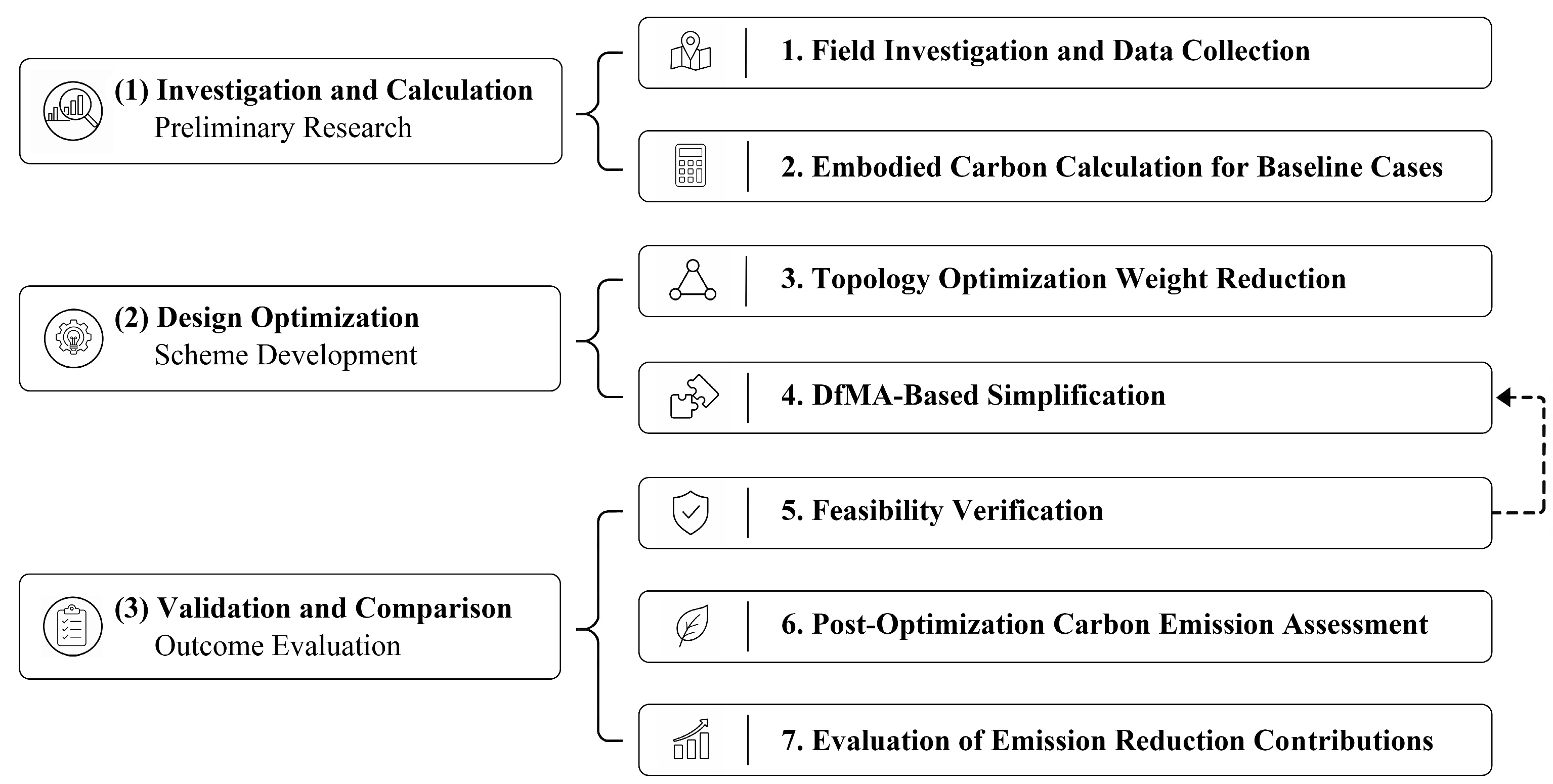
This study focuses on landscape structures (benches, pavilions, and bridges) within the Beijing Olympic Forest Park as specific research subjects. It establishes a systematic research framework encompassing “case investigation–initial carbon emission accounting–topology optimization–DfMA simplification–structural verification–post-optimization carbon emission accounting–emission reduction comparison” (
Figure 1).
First, through on-site surveys, this study systematically collected fundamental data on the typical structures to calculate the baseline embodied carbon emissions. Second, Autodesk Fusion software (version 2704.1.23, 64-bit, Educational License) was utilized to identify the primary load-bearing paths of the structures, based on which topology optimization was conducted to achieve preliminary weight reduction. Subsequently, DfMA principles were introduced to translate the highly complex generated topological forms into structural systems that are easy to manufacture, transport, and assemble. Finally, after verifying structural feasibility, the embodied carbon emissions of each design were calculated, allowing for a systematic comparison of their efficacy in structural weight reduction and embodied carbon reduction.
3.1. Study Case Selection
To systematically understand the current material and structural status of landscape structures in the Beijing Olympic Forest Park, this study conducted field surveys to investigate the basic conditions of landscape benches, pavilions, and bridges, including key indicators such as materials, structural forms, dimensions, and weight grades (
Table 1). The survey results indicate that some current landscape facilities suffer from component weight redundancy, insufficient material utilization, and low structural efficiency, highlighting a potential for lightweight optimization.
Based on the survey results, this study selected three typical landscape structures as analysis cases: a landscape bench (No. 7), a landscape pavilion (No. 1), and a landscape bridge (No. 3). The selection criteria prioritized objects with high usage frequency, relatively large weight grades, and representative structural characteristics (
Table 2). The selected cases provide comprehensive coverage of a small-scale concrete structure, a medium-scale steel system, and a large-scale concrete structure. This selection aims to compare and verify the applicability and carbon reduction efficacy of the topology optimization-DfMA synergistic method across multiple scales, material types, and structural systems.
3.2. Carbon Emission Calculation Method
This study employs the Life-Cycle Assessment (LCA) method to calculate the embodied carbon emissions. Based on the construction characteristics of the landscape structures, the life-cycle embodied carbon is divided into the materialization phase and the demolition phase [
42]. The materialization phase includes material production, material transportation, and construction; the demolition phase encompasses building demolition, waste transportation, waste disposal, and recycling (
Table 3).
The total embodied carbon emissions of a structure equal the sum of emissions from material production to waste disposal, minus the carbon reduction generated by recycling:
The impact of topology optimization and DfMA simplification on carbon emissions is primarily reflected in material consumption, construction methods, labor hours, and recycling proportions. This study prioritizes the default values from the “Standard for Building Carbon Emission Calculation” of China (GB/T 51366-2019) [
43] and incorporates the existing literature to adjust values for additive manufacturing (3D printing) and recycling scenarios.
where Csc is the carbon emission during the material production stage (kgCO
2e), Mi is the consumption of the i-th main material (m
3), and Fi is the carbon emission factor of the i-th main material (kgCO
2e/m
3).
This study categorized and quantified the structural materials obtained through on-site survey. The carbon emission factors are sourced from GB/T 51366-2019.
- 2.
Material Transportation Stage:
where Cys is the carbon emission during the material transportation stage (kgCO
2e), Mi is the consumption of the i-th main material (t), Di is the average transportation distance of the i-th main material (km), and Ti is the carbon emission factor for transporting a unit weight of the i-th material over a unit distance [kgCO
2e/(t·km)].
Transportation distances were determined based on default values in GB/T 51366-2019: 40 km for concrete and 500 km for other materials. The factor for light gasoline vehicles is 0.334 kgCO2e/(t·km). For transporting concrete for the bridge, heavy diesel trucks (46 t payload) were assumed, with a factor of 0.057 kgCO2e/(t·km). Trip counts were calculated based on actual volumes.
- 3.
Construction Stage:
where Cjz is the construction stage carbon emission (kgCO
2e), Ejz,i is the total consumption of the i-th energy source (kWh or kg), EFi is its emission factor (kgCO
2e/kWh or kgCO
2e/kg), Pi is the total labor input (man-days), and Fp is the labor emission factor (kgCO
2e/man-day).
The construction primarily utilized woodworking saws, profile steel shears, spiral drills, and welding machines. Power and labor parameters were adopted from GB/T 51366-2019 defaults. The electricity emission factor used was 0.8 kgCO
2e/kWh (North China) [
44], and labor was set at 10.1 kgCO
2e/man-day [
45]. For irregular components that are difficult to build, additive manufacturing energy consumption was adjusted: 2.72 kWh/kg for steel [
46] and 35.2 kWh/m
3 for concrete 3D printing [
47].
- 4.
Building Demolition Stage:
This stage is calculated using an estimation method, assumed to be 10% of the carbon emissions generated during the construction stage [
48].
- 5.
Waste Transportation Stage:
This stage is referenced to Equation (3). The default average distance from the demolition site to secondary markets, waste treatment facilities, and landfills is set at 50 km [
49].
- 6.
Waste Disposal Stage:
where Ccl is the disposal stage carbon emission (kgCO
2e), Mi is the consumption of the i-th material (t), Rtm,i and Rfs,i are the landfill and incineration proportions (%), and Li and Bi are their respective emission factors (kgCO
2e/t).
Based on the relevant literature [
45,
50,
51], this study determined the proportions in
Table 4 to calculate the corresponding emissions.
- 7.
Recycling Stage
where Chs is the carbon emission reduction from recycling (kgCO
2e), Csc,i is the material production emission of the i-th material (kgCO
2e), and Rhs,i is its recycling proportion (%).
Recycling substitutes part of the primary raw material production and is counted as a carbon offset (deducted by 50% according to GB/T 51366-2019). For the DfMA designs, due to higher component standardization, clear assembly, and superior conditions for material separation, the recycling proportions for steel and concrete were adjusted upward [
52,
53,
54,
55].
3.3. Topology Optimization Method
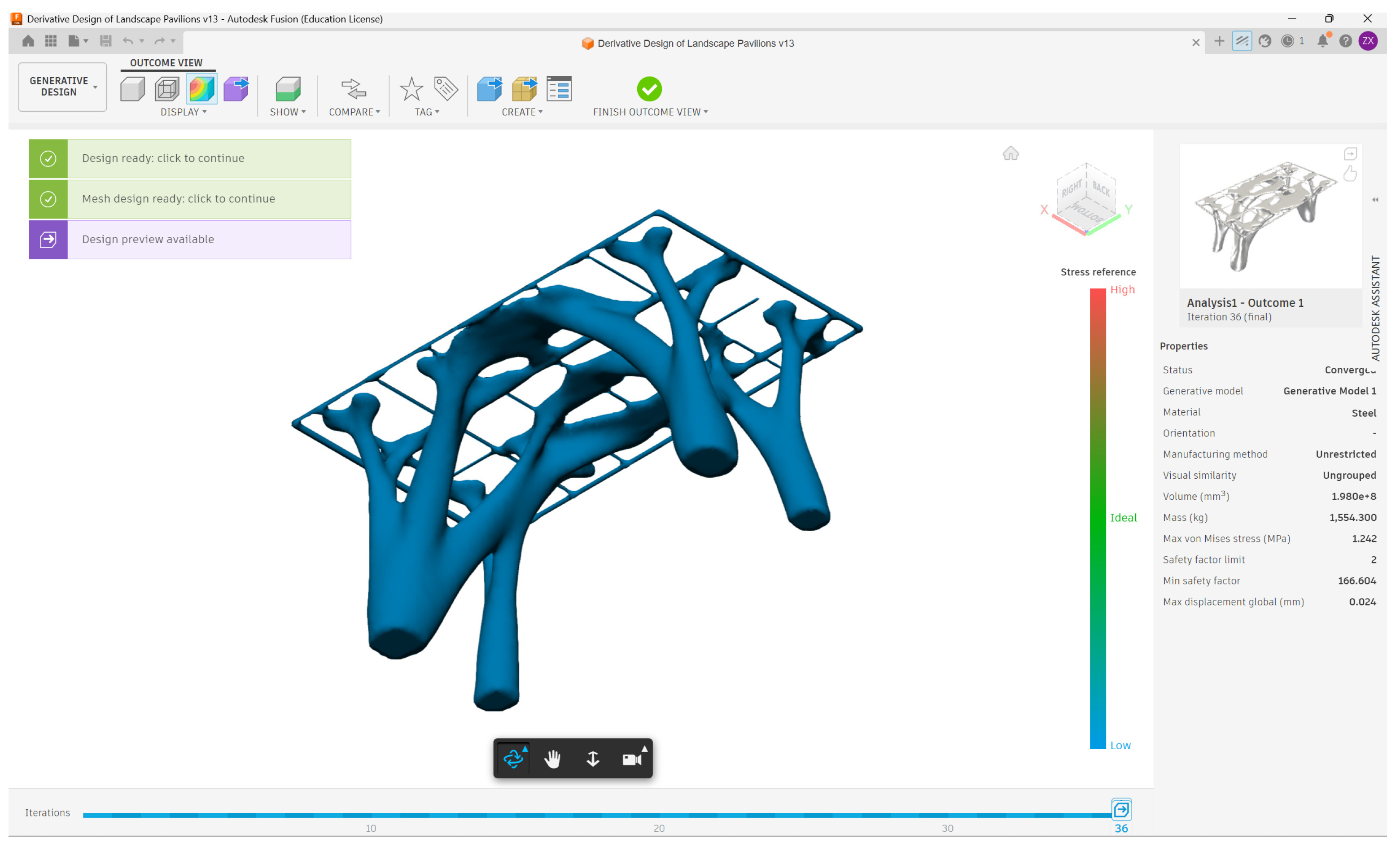
This study utilized Autodesk Fusion to perform topology optimization on the three structures (
Figure 2). The goal of this step is not to generate the final buildable form, but to identify the primary material distribution and core load-bearing paths within specific boundary conditions. This strips away redundant, non-load-bearing material to provide a prototype for subsequent DfMA translation.
The process followed a workflow of “defining design domains–setting preserved regions–applying loads and constraints–calculating optimal material paths.” In the model, the primary load-bearing or supporting sections subject to material reduction are defined as design domains. The parts directly related to functional usage, component connections, and load transmission at supports are set as preserved regions. And the spaces where structural intrusion is prohibited—such as areas for passage, activities, legroom, and under-bridge clearance—are designated as obstacle regions. The optimization objective is to reduce non-essential material consumption by more than 50% while satisfying the basic structural load-bearing and overall stiffness requirements (
Table 5).
3.4. DfMA Simplification Method
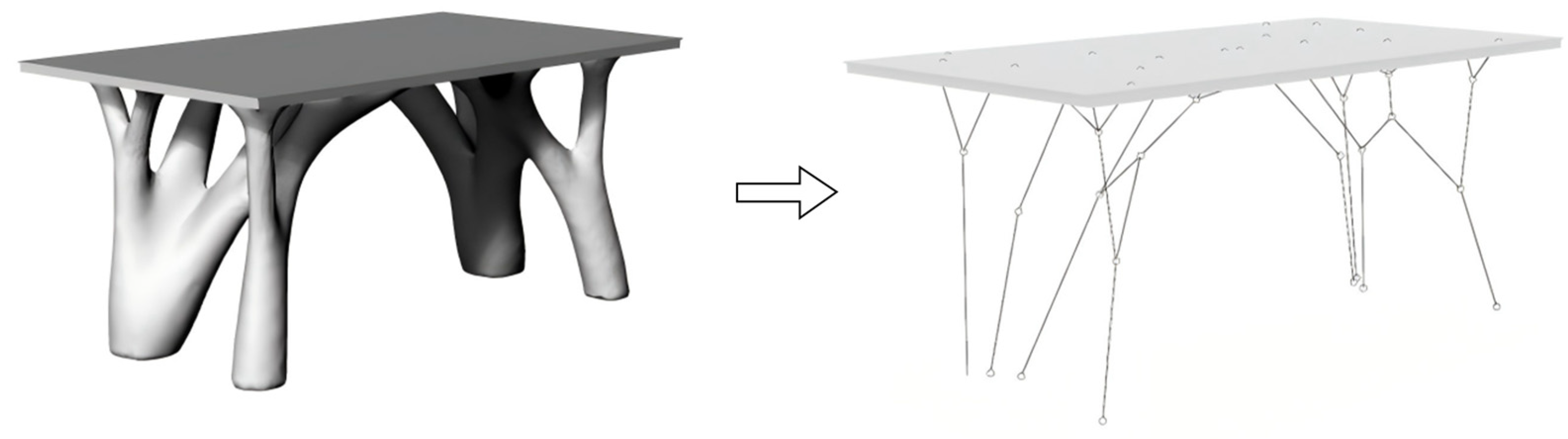
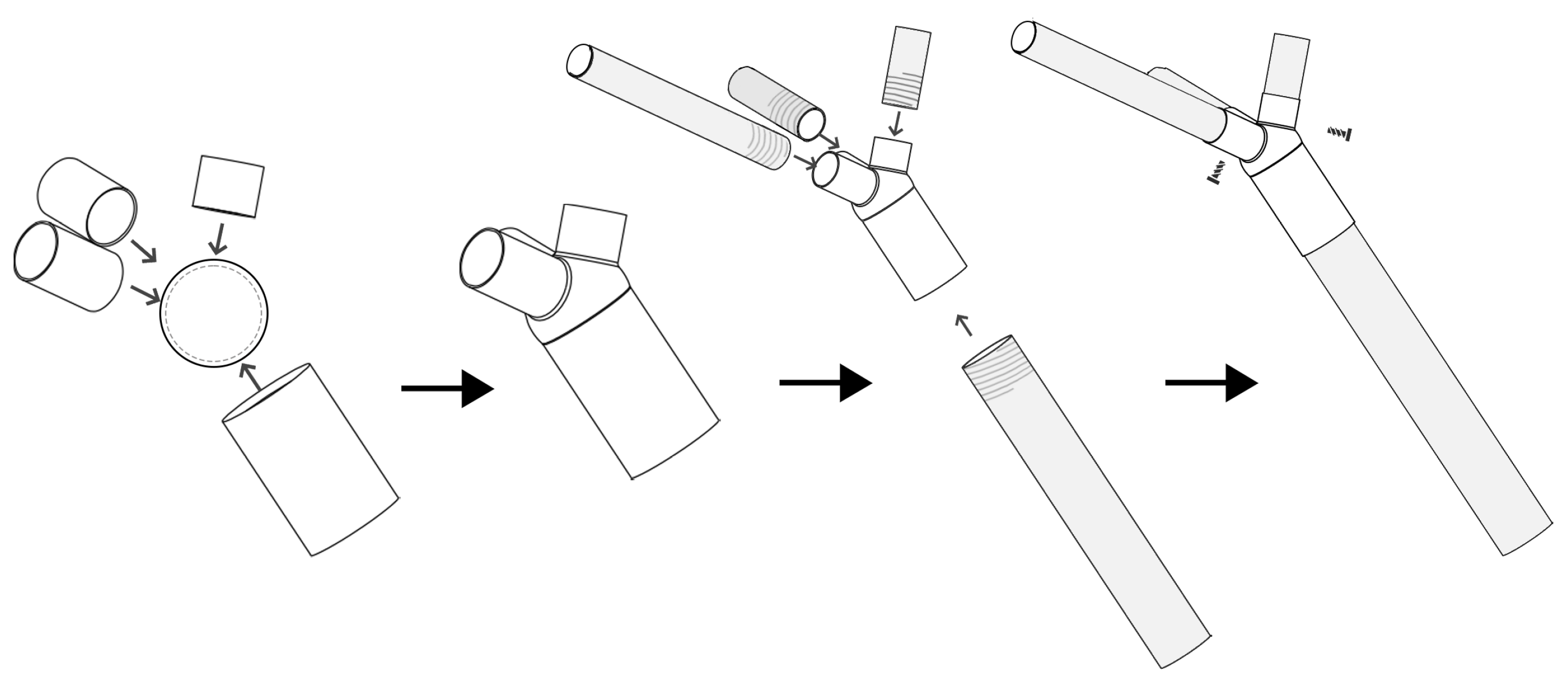
The DfMA simplification adheres to the core principles of “retaining load-bearing paths, standardizing components, and enabling joint assembly,” transforming complex free-form surfaces, intricate nodes, and continuous irregular entities into standardized component systems that are easy to manufacture, transport, and assemble on-site (
Figure 3). This morphological simplification relies on explicit, fundamental design rules rather than solely engineering judgment.
The high-density material regions identified by topology optimization are abstracted into a logically continuous geometric skeleton.
Complex, continuous free-form entities are discretized into physical units that comply with standard manufacturing and logistics constraints.
To minimize non-standard fabrication, component and connection types are reduced through modular repeatability.
Complex continuous intersections are converted into modular, reversible joints to facilitate rapid on-site assembly and end-of-life deconstruction.
To ensure reproducibility during this translation process, the numbers and sizes of the standardized modules were determined by mapping the required load paths directly to commercially available standard profiles, thereby avoiding custom mold manufacturing. These principles facilitate structural rationalization by merging complex, free-form geometries into regularized forms while strictly preserving primary load-bearing paths. To enhance manufacturing efficiency, morphologically similar components are consolidated into repeatable, standardized units. Furthermore, irregular junctions are transformed into standardized joint systems that support modular prefabrication, bolting, or sleeving, thereby ensuring structural feasibility and ease of assembly [
56].
3.4.1. DfMA Simplification of the Landscape Bench
Simplification for the bench focuses on the load transfer relationship between the seat and the supports. The core paths transmitting loads downwards are retained, and free-form supports are converted into plates, rods, diagonal braces, or arched ribs that can be conventionally manufactured. This transforms the bench into an easily manufacturable system.
3.4.2. DfMA Simplification of the Landscape Pavilion
For the pavilion, simplification centers on its tree-like spatial support system. Primary load-bearing paths were first extracted in Rhino 8.0, abstracting continuous irregular entities into rod centerlines, categorized into main trunks, primary branches, secondary branches, and local supports based on load transfer hierarchy. The uneven supports were uniformly translated into standard hollow circular steel tubes. Multi-directional spherical sleeve joints were introduced at branch intersections (
Figure 3).
3.4.3. DfMA Simplification of the Landscape Bridge
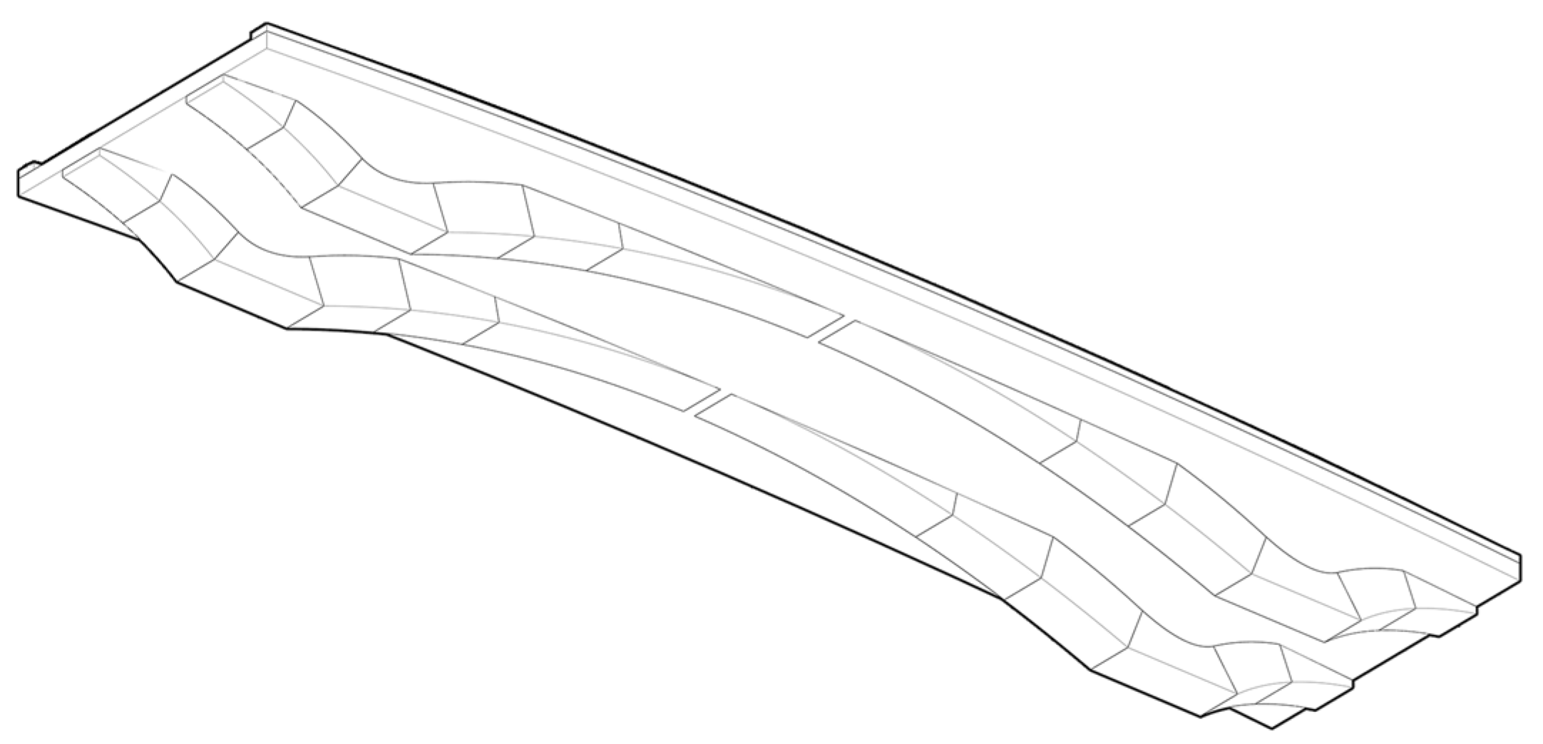
The bridge simplification extracted the main endpoints of the topology-optimized structure, combining them with the midpoints of the bridge deck’s underside to generate precise arched control lines. These were organized into an assembled “complete central arch and two end half-arches” configuration. The central arch was divided into six standardized blocks, and each side’s half-arch was split into two independent components. Structural interfaces were standardized into base joints, transforming non-standard solid entities into a modular arched block system ready for manufacturing, transport, and assembly.
3.5. Result Verification Method
To verify the structural feasibility of the topology optimization and DfMA designs, static analysis models were established for all three structures. This verification serves the conceptual design stage to macroscopically assess whether load-bearing paths, overall stiffness, and strength are within reasonable ranges.
For the concrete structures (bench and bridge), static stress analyses were conducted using Autodesk Fusion to extract key indicators like von Mises equivalent stress, maximum total displacement, and safety factors. Because the landscape pavilion is a complex spatial tree-like steel tube structure, Dlubal RSTAB 9.14 software was utilized for verification. In RSTAB, steel parameters, cross-sectional properties, support constraints, and equivalent vertical top loads were assigned to compute nodal displacements, member deformations, internal forces, and strains.
4. Results and Analysis of Topology Optimization and DfMA
4.1. Topology Optimization Results
The analysis indicates that topology optimization demonstrates significant potential for material reduction across landscape structures of varying scales, material types, and structural systems. However, notable variations exist in weight reduction efficiency and morphological evolution characteristics among the cases (
Table 6,
Table 7 and
Table 8).
Among the three objects, the landscape bench achieved the highest weight reduction ratio. This is primarily because its initial design consisted of a heavy, solid concrete block with material usage far exceeding actual load-bearing requirements. For the concrete support, topology optimization was conducted under three different support conditions (arranged along the long side and short sides). The results show that the weight reduction rates for all three optimized designs exceeded 80% (
Table 6). Notably, the long-side support configuration achieved a material reduction of up to 85.26% through an approximate triangular load-bearing structure. This demonstrates that optimizing the spatial distribution of support materials can drastically cut concrete consumption.
The initial design of the landscape pavilion utilized a conventional frame system, and its optimization focused on simplifying spatial load-bearing paths. Following topology optimization, the structure evolved into a biomimetic tree-like branching morphology, restructuring the original uniform frame supports into a distinct “trunk–branch” load transfer topology. This achieved a 19.18% reduction in total material volume (
Table 7). However, the continuous solid morphology generated by this optimization is highly complex, suffering from localized excessive mass and highly irregular joints. This indicates that for complex spatial structures, topology optimization results can rarely be directly translated into practical, lightweight construction schemes.
As the largest structure among the three cases, topology optimization of the landscape bridge effectively trimmed the redundant volume of the concrete support beneath the bridge deck, achieving a weight reduction rate of 25.35% (
Table 8). Although the relative weight reduction percentage for the landscape bridge is lower than that of the landscape bench, its absolute material reduction (a total saving of 79,632 kg of concrete) is exceptionally prominent. This outcome validates the lightweight design value of topology optimization in the large-scale landscape structures.
4.2. DfMA Simplification Results
4.2.1. DfMA of Landscape Bench
DfMA simplification of the landscape bench focuses on the support system beneath the seat. Based on the preceding topology optimization results, three candidate DfMA options were constructed (
Table 9).
Evaluating material consumption alongside component standardization reveals that the long-side support configuration performs best. This scheme reconstructs the lower support into repeatable, assemblable triangular modules with clear load transfer logic, reducing the total mass by an additional 7.27% compared to the pure topology optimization design. These selected DfMA schemes were considered preferable because they achieved the optimal balance among minimal material consumption, highest part repeatability, and overall ease of assembly compared to other potential geometric translations. Composed of identical repeating support units, this design achieves high standardization, providing an excellent foundation for modular factory fabrication and rapid on-site assembly.
The three-short-side support design translates continuous load paths into arched plate components, offering good structural integrity. However, it increases processing requirements for curved plates and joint connections. The two-short-side support design relies on end supports and longitudinal diagonal braces for load transfer. While it provides high overall stiffness, it leads to a relative increase in material consumption. Although both short-side support options offer certain conveniences for conventional fabrication and construction, they fail to achieve further material savings.
4.2.2. DfMA of Landscape Pavilion
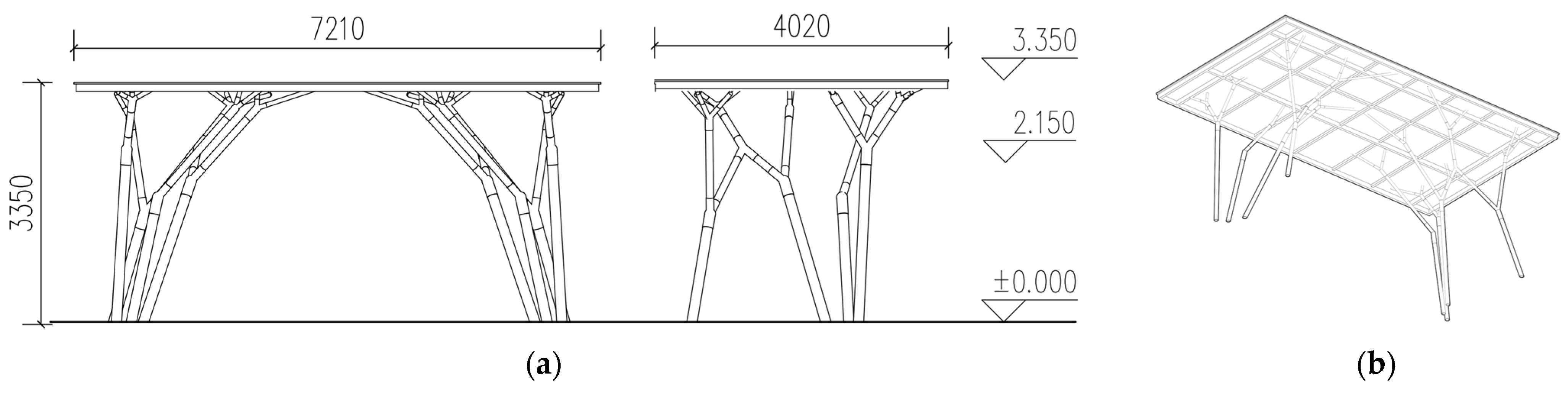
During the DfMA of the landscape pavilion, the branching tree-like characteristics from topology optimization were adopted as the structural prototype, which was subsequently transformed into a tree support system composed of standard hollow circular steel tubes (
Figure 4). This DfMA scheme not only drastically simplifies the manufacturing and fabrication difficulties, but also decreases the total weight to 1233.39 kg, representing an additional weight reduction of 20.65% compared to the topology optimization results.
Following DfMA, the support system of the pavilion is disassembled into 6 main trunks, 14 primary branches, 26 secondary branches, and 6 localized tertiary branches. Members across all layers employ hollow circular steel tubes, configured with matching cross-sectional specifications based on their load transfer hierarchy. This strategy effectively avoids the manufacturing obstacles associated with continuous, variable-section components. As illustrated in
Figure 5, standardized spherical sleeve joints were introduced to replace complex on-site welding, facilitating rapid bolt assembly and end-of-life deconstruction.
4.2.3. DfMA of Landscape Bridge
Through DfMA simplification, this bridge was restructured into an assemblable system consisting of an “upper bridge deck slab–central arch–two end half-arches–base joints” (
Figure 6 and
Figure 7). The lower substructure was converted from a heavy, non-standard solid entity into a modular, segmented arch combination structure.
The structural system can be systematically categorized into modules such as bridge deck slabs, central arch blocks, side half-arch blocks, and base joints (
Figure 8). Furthermore, the central arch is divided into six standardized arch blocks, and the side half-arches are split into two independent components each. Due to the bilateral symmetry of the overall structure, components can be fabricated using mirror imaging, thereby minimizing component variety and mold requirements.
Although the total weight of the landscape bridge DfMA design (244,560 kg) was not reduced further compared to the topology optimization design, the scheme successfully enables high-precision factory prefabrication and rapid on-site assembly of the arch blocks. This modular characteristic significantly reduces construction difficulty while granting excellent deconstructability, which ultimately boosts material recycling rates at the end of its life cycle.
4.3. Structural Feasibility Verification Results
To evaluate whether the structures of DfMA serve as a sound mechanical foundation for further development, this study conducted structural feasibility verifications (
Table 10). These verifications focus on macro-level load-bearing feasibility and do not extend to local connection capacities, bolt stresses, weld fatigue, foundation anchoring, or complex construction-stage load cases.
For the three DfMA options of the landscape bench, static stress analyses were conducted under a vertical load of 3.0 kN. The calculations show that the minimum safety factors for all three options are significantly higher than 1.5, confirming that they are absolutely safe under the established load case (
Table 11). Although the long-side support design generates higher internal stress and displacement responses, it fully satisfies conceptual safety while exhibiting the highest potential for standardized modular assembly. The three-short-side support configuration balances load continuity with material efficiency, while the two-short-side support setup exhibits the smallest characteristic displacement, indicating the highest overall structural stiffness.
For the landscape pavilion, 3D static analysis of the spatial rod system was executed via RSTAB software. The results show a maximum displacement of only 0.15 mm and a maximum combined stress of approximately 1.90 MPa. These data confirm the macro-level structural feasibility of the pavilion’s DfMA scheme.
For the landscape bridge, static stress analysis via Autodesk Fusion indicates that the DfMA scheme for the arch bridge achieves a minimum safety factor of 3.71, a maximum von Mises stress of 3.86 MPa, and a maximum displacement of only 2.90 mm. These findings verify that the overall structure exhibits no signs of localized strength deficiencies or overall stiffness issues.
5. Analysis of Carbon Emission Calculation Results
5.1. Changes in Embodied Carbon Emissions Before and After Optimization
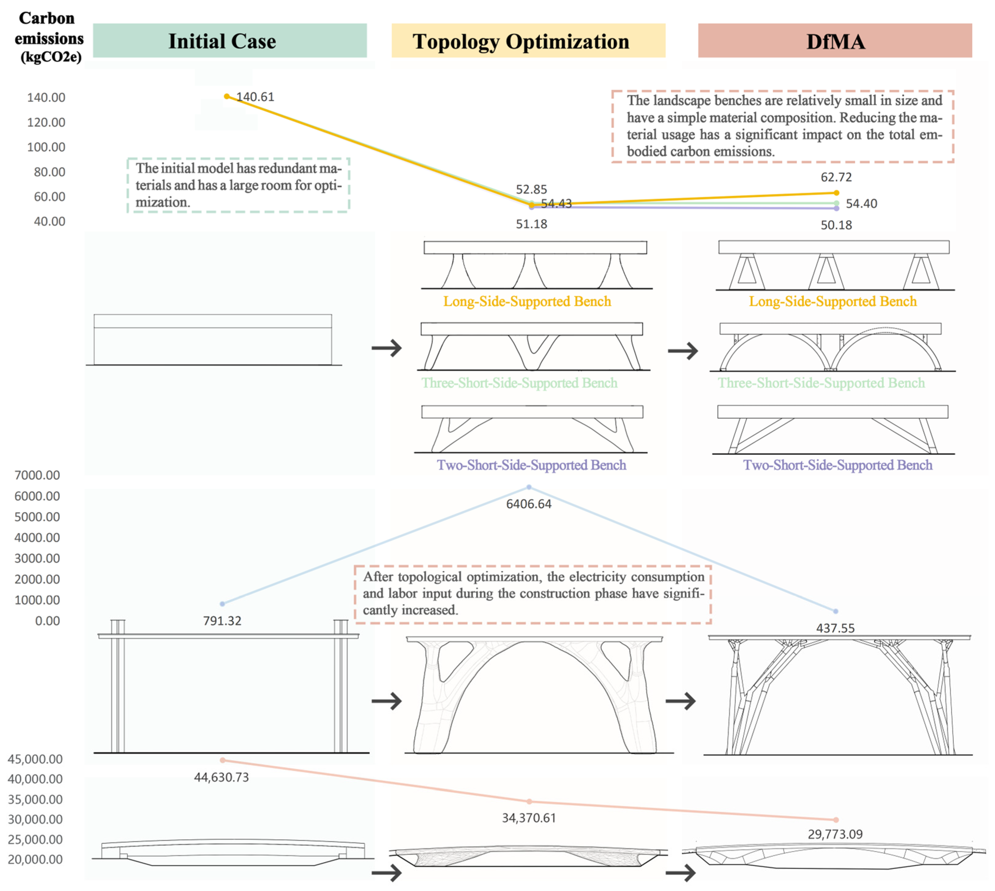
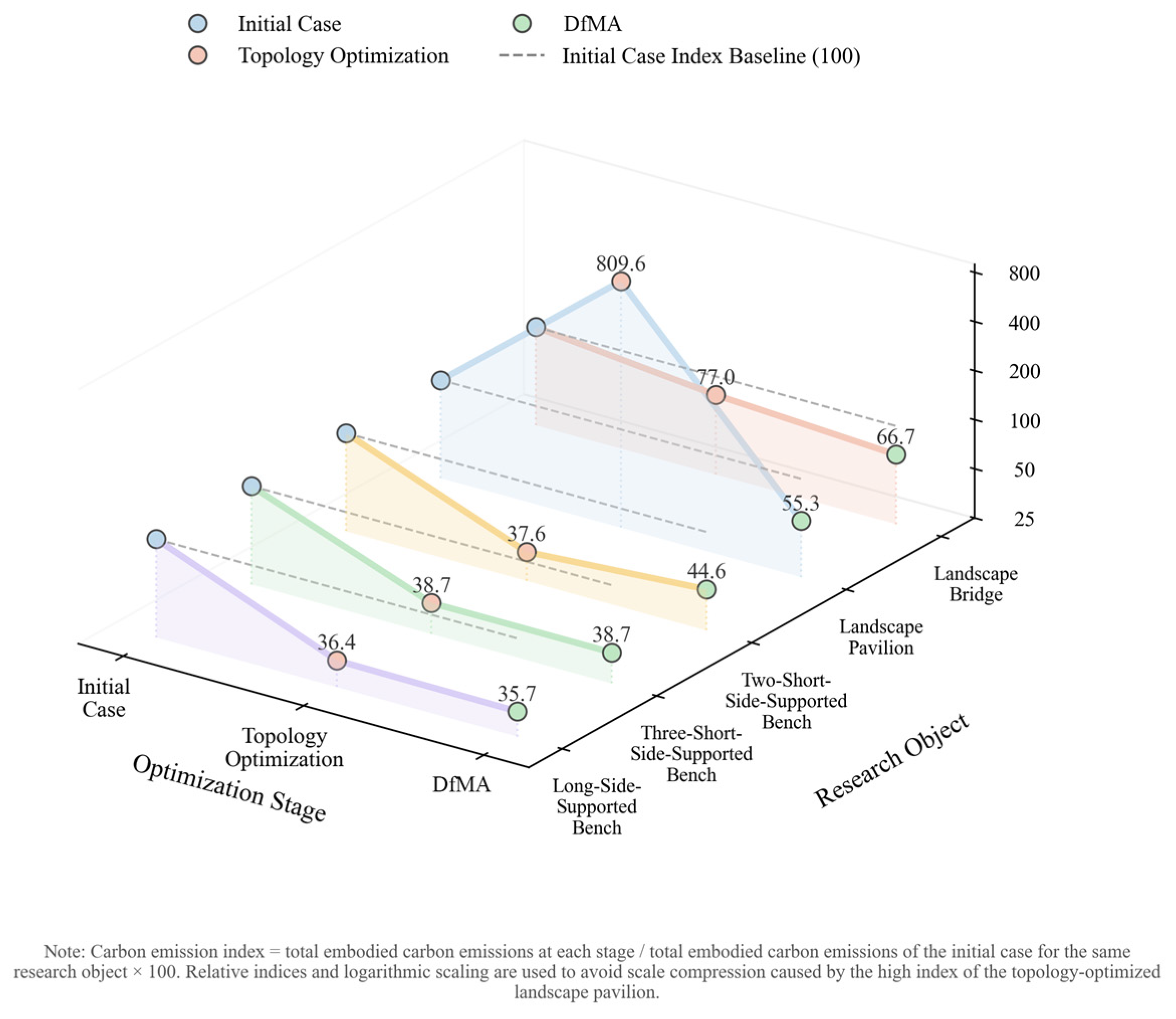
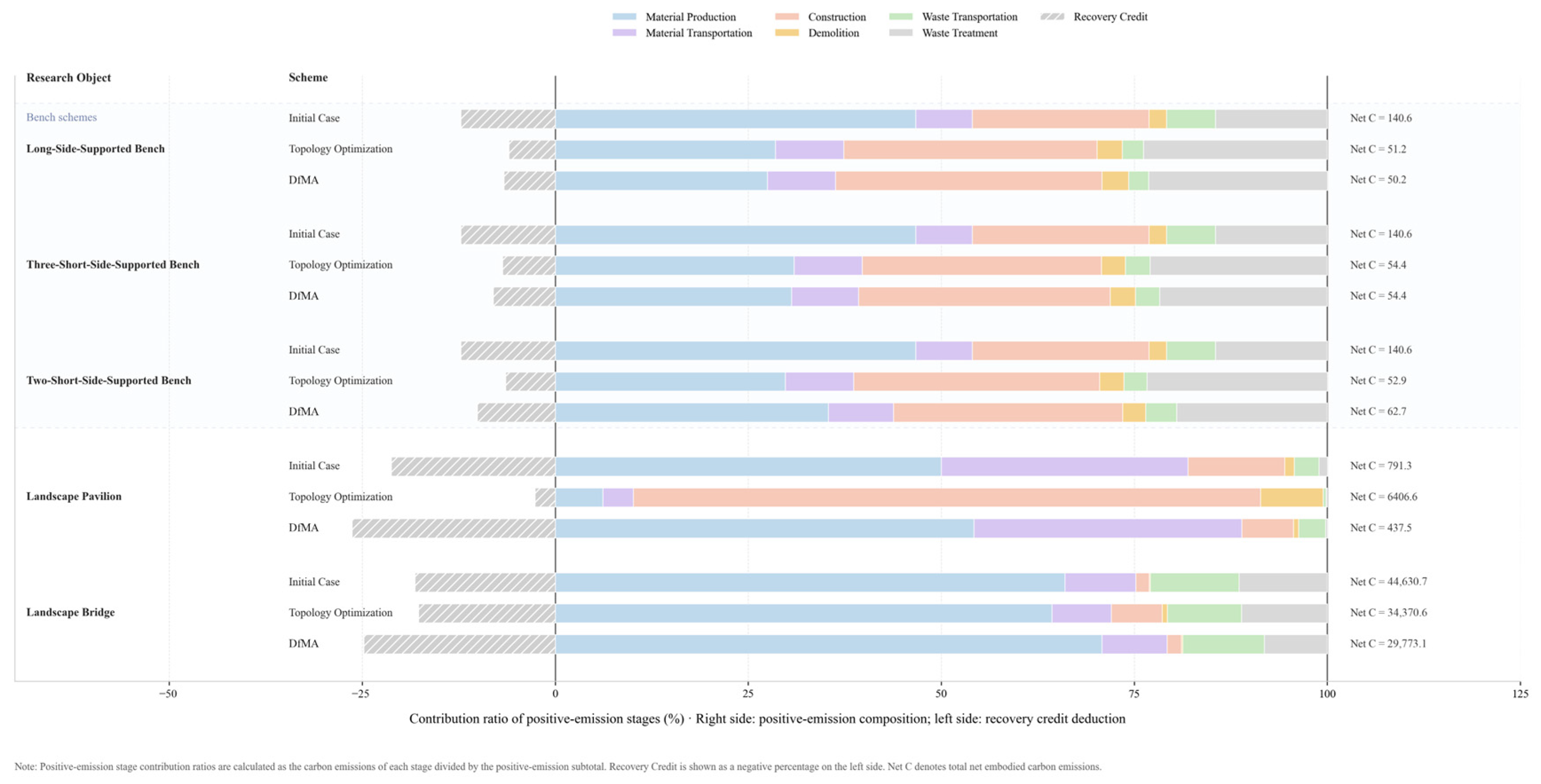
To evaluate the impact of topology optimization and DfMA on life-cycle embodied carbon emissions, this study compared the initial schemes, topology-optimized schemes, and DfMA-translated schemes for the three types of landscape structures (
Table 12,
Figure 9 and
Figure 10). The results indicate that although topology optimization can reduce material usage, the total life-cycle carbon emissions are still influenced by construction methods, component complexity, and recycling rates. In contrast, the DfMA schemes successfully achieved emission reductions across all three landscape structures compared to the initial schemes by improving manufacturing feasibility, logistics and transportation efficiency, on-site assembly, and the recyclability of disassembled materials.
Among all cases, the landscape pavilion best illustrates the limitations of topology optimization methods in practical applications. Although the topology optimization of the pavilion reduced its weight by 19.18%, its total life-cycle embodied carbon emissions surged by 709.61%. This result primarily stems from the high degree of geometric irregularity in the topology-optimized steel components, which necessitated the use of additive manufacturing processes during the construction phase, thereby leading to an increase in electricity consumption and labor inputs. Therefore, despite achieving certain emission reductions during the material production and transportation phases, the adverse effects generated during the construction and recycling phases outweighed the benefits of material savings. In contrast, the DfMA scheme reduced the pavilion’s total embodied carbon emissions to 437.55 kgCO2e, achieving a 44.71% carbon reduction rate compared to the initial scheme. This indicates within the selected cases the important role of constructability-oriented geometric regularization design in realizing low-carbon outcomes for complex spatial structures.
All three optimized schemes for the landscape bench achieved emission reductions relative to the initial scheme. Because the bench has a relatively small volume but high concrete usage, the reduction in material volume exerted a strong impact on total embodied carbon. Although the total carbon emissions of the topology-optimized schemes were slightly lower than those of the corresponding DfMA schemes, the DfMA schemes still maintained significant carbon reductions, with an average reduction rate of over 60%. Furthermore, they exhibit superior engineering feasibility in terms of industrialized manufacturing, on-site assembly, and recyclability.
The initial scheme of the landscape bridge had a total embodied carbon emission of 44,630.73 kgCO2e, representing the highest carbon emission magnitude among the three research objects. While topology optimization reduced concrete material usage, the increased construction energy consumption and the loss in recycling benefits weakened the overall emission reduction effect. After introducing DfMA for modular simplification, the total embodied carbon emissions of the landscape bridge scheme dropped to 29,773.09 kgCO2e, achieving a carbon reduction rate of 33.29%. This result indicates that for large-volume concrete landscape structures, low-carbon design must not solely rely on structural topology weight reduction. Instead, it requires a multi-dimensional synergistic consideration of material savings alongside component manufacturability, logistics efficiency, low-energy assembly, and recycling scenarios.
5.2. Changes in Embodied Carbon Emissions Across Various Stages
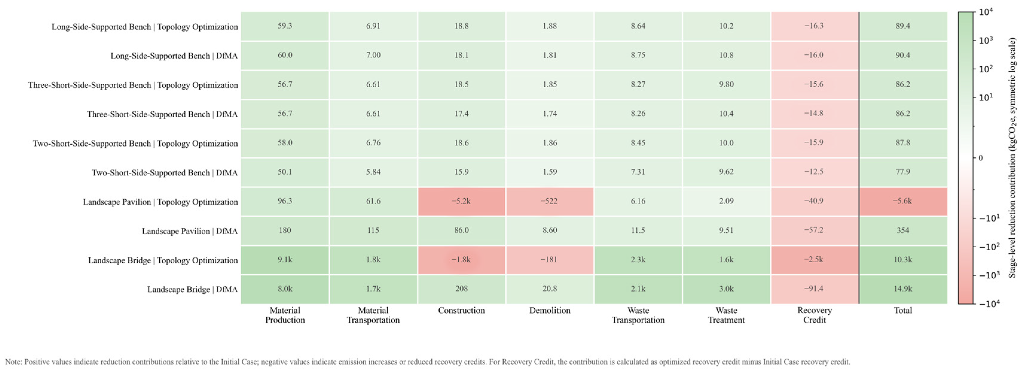
To identify the carbon reduction contributions of each stage throughout the life cycle, this study analyzed the emission reductions of each optimized scheme compared to the initial baseline scheme across various life-cycle stages (
Figure 11 and
Figure 12). Since the recycling stage serves as a carbon offset item, it was calculated as “recycling offset amount of the optimized scheme — recycling offset amount of the initial scheme”. A positive emission reduction contribution indicates that the specific stage helps lower total embodied carbon emissions. Conversely, a negative value implies that the stage resulted in additional carbon emissions or a loss in recycling offsets.
Analysis of the emission reduction results across different stages reveals that topology optimization primarily yields emission reduction contributions during the material production, material transportation, waste transportation, and waste disposal stages. Among these, the carbon reduction contribution of the material production stage is the most prominent, accounting for an average of over 60% of the total reductions. This is mainly attributed to the cutback in material consumption achieved through topology optimization. Consequently, the reduction in material volume also drove a synchronous decline in carbon emissions during the subsequent logistics, transportation, and waste disposal stages.
However, topology-optimized schemes are highly likely to exert adverse impacts during the construction, building demolition, and recycling stages. This drawback is particularly evident in the landscape pavilion, where irregular steel components led to a massive surge in carbon emissions during the construction phase (a 41.5-fold increase compared to the initial scheme). The fundamental cause is that energy-intensive metal additive manufacturing significantly escalated electricity consumption. This demonstrates that pure material reduction via topology optimization does not equate to life-cycle carbon reduction.
In contrast, the comprehensive emission reduction rates of the DfMA schemes ranged between 33% and 64%, exhibiting stronger robustness in carbon reductions across all stages. With the exception of the recycling offset item—which experienced a reasonable absolute value decrease due to the reduction in the total material baseline—the carbon emissions in all other positive-emission stages decreased compared to the initial schemes. Notably, their carbon emission levels during the construction phase were significantly improved compared to the topology-optimized schemes. This suggests that component geometric simplification and assembly design executed through DfMA can effectively mitigate the additional carbon emissions triggered by complex construction.
In summary, topology optimization affects carbon emissions primarily in material-related stages through structural material optimization. Meanwhile, the DfMA method further ameliorates the construction, assembly, and recycling conditions of the structures, facilitating emission reduction contributions simultaneously across multiple stages. Therefore, the deep synergy of topology optimization and DfMA serves as a suitable and comprehensive optimization pathway for driving landscape structures toward high-performance and low-carbon practices.
5.3. Uncertainty and Sensitivity Analysis
To improve confidence in the reported carbon reductions and enhance the scientific robustness of the study, a sensitivity analysis was conducted on key life-cycle parameters. A ±10% variation was applied to material consumption, transportation distance, construction energy consumption, and recycling rate. The results indicate that material consumption had the greatest influence on total emissions, causing a ±9.71% change in the DfMA scheme, followed by recycling rate (about ±5.75%), transportation distance (±2.56%), and construction energy consumption (±0.05%). Under all single-parameter scenarios, the DfMA schemes maintained a 32.38–34.86% carbon reduction compared with the initial designs. Even under a combined conservative scenario, the reduction rate remained 32.41%, confirming the robustness of the proposed framework.
6. Discussion
This study indicates that the carbon reduction benefits of topology optimization in landscape structure design are highly conditional. For heavy concrete structures, because the optimization direction mainly focuses on the reduction in solid materials, minimizing material consumption can directly lower carbon emissions stemming from material production, logistics, and waste disposal. However, for spatial branching steel structures such as the landscape pavilion, the continuous non-standard forms directly generated by topology optimization will exacerbate geometric complexity, subsequently driving up life-cycle carbon emissions. Therefore, topology optimization is not necessarily synonymous with low-carbon design. Its effectiveness is contingent upon a comprehensive integration of material types, structural forms, manufacturing methods, and recycling scenarios. It must be emphasized that the findings of this study are closely tied to the specific structural redundancy of the original designs. The proposed framework is demonstrated through these selected representative cases rather than statistically validated across a broad sample of landscape structures.
The DfMA method acts as a critical bridge connecting computational optimization and constructable implementation in this study. Through component standardization, joint geometric regularization, and assembly method optimization, DfMA can reduce the processing difficulty of complex irregular components and enhance both the disassemblability and material recycling potential of parts. In terms of practical implementation, integrating DfMA into the topology optimization workflow introduces critical manufacturability constraints early in the design process. This integration can substantially lower the cost implications associated with bespoke molds, material waste, and specialized on-site labor. While this approach proves effective for the landscape amenities studied, its applicability naturally extends to other small-scale architectural structures, such as pedestrian bridges and modular urban furniture (
Table 13). However, scaling this framework to high-rise buildings or complex long-span structures would require further considerations regarding dynamic loads, joint fatigue, and more stringent safety regulations.
DfMA circumvents the need for bespoke, energy-intensive manufacturing techniques (such as large-scale metal 3D printing) by enabling the use of conventional, low-energy fabrication methods. By synthesizing key performance indicators across the case studies, it is evident that the true value of the framework lies not just in material reduction, but in actively lowering manufacturing complexity and improving supply chain logistics.
Furthermore, the core pathways and focuses for low-carbon optimization vary among landscape facilities of different structural types. Concrete landscape benches rely primarily on reducing the solid volume of supports to achieve carbon reductions. Although the topology weight reduction ratio of the concrete landscape bridge was relatively low, its massive initial baseline allowed it to contribute the highest absolute material reduction and carbon emission reduction. On the other hand, because the landscape pavilion possesses both the 3D characteristics of a steel structure and complex nodes, its low-carbon benefits are highly dependent on the subsequent geometric simplification via DfMA. Thus, it is evident that when conducting low-carbon designs for landscape structures, appropriate optimization strategies and form simplification methods must be selected according to their material properties, structural forms, and spatial scales.
Although this study provides a methodological reference for low-carbon landscape construction, it still harbors certain limitations. First, the current DfMA simplification process has not yet fully realized automatic derivation via parametric algorithms. Second, in the accounting of embodied carbon emissions, default parameters were adopted for certain construction energy consumption, demolition losses, and waste disposal ratios. Third, this study has limitations regarding constructability assessment. While the framework is DfMA-oriented and effectively evaluates structural performance and embodied carbon, it does not quantitatively evaluate several key objectives of DfMA. Specifically, performance indicators such as manufacturing complexity indices, assembly time efficiency, precise modularization constraints, and localized fabrication effort were not quantitatively measured. Future research could focus on quantitative DfMA metrics, BIM-LCA data linkages, multi-objective optimization algorithms for carbon reduction, and on-site measured construction data to further enhance the scientific rigor and engineering application accuracy of the “topology optimization–DfMA” low-carbon design framework.
7. Conclusions
Taking the landscape bench, pavilion, and bridge in the Beijing Olympic Forest Park as specific research objects, this study proposed a low-carbon design method for landscape structures driven by topology optimization and DfMA. By conducting structural verification and life-cycle embodied carbon emission accounting, the comprehensive effectiveness of this synergistic method was evaluated. The primary research conclusions are summarized as follows:
Topology optimization can identify the force transmission paths of landscape structures and guide the refined reduction in materials. In this study, the lightweighting effect of the concrete landscape bench was the most pronounced, with structural weight reduction rates exceeding 80% under three distinct boundary conditions. While the mass of the optimized concrete landscape bridge was reduced by 25.35%, its massive baseline contributed to the highest absolute volume of material reduction. The mass of the optimized steel structure landscape pavilion was reduced by 19.18%, yielding a tree-like branching topological structure with clearer force transmission paths.
DfMA is capable of simplifying topology optimization results into manufacturable, transportable, and assemblable component systems. In practical application, the landscape bench elevated its structural standardization level through highly repetitive support modules. The landscape pavilion mitigated the manufacturing difficulties of spatial irregular structures by introducing standard hollow steel tubular trusses. The landscape bridge achieved clear geometric boundaries for its components and well-organized on-site assembly through the modular partition. Compared to pure topology-optimized forms, the DfMA simplification did not lead to a massive rebound in structural weight during the geometric regularization process. Notably, the landscape pavilion achieved an additional 20.65% weight reduction relative to the initial topology results.
Compared to a single topology optimization pathway, the DfMA synergistic scheme exhibited more stable carbon reduction benefits across all stages, with its life-cycle embodied carbon emissions decreasing by an average of 51.80%. Among them, the carbon reduction intensity of the landscape bench DfMA scheme was the highest, attaining a reduction rate between 55.40% and 64.31%. The landscape pavilion scheme successfully reversed the detrimental flaws of the pure topology scheme, achieving a 44.71% emission reduction. The carbon reduction rate of the large-volume landscape bridge scheme also reached 33.29%. The DfMA method actualized a synergistic decline in carbon footprints across multiple stages through systemic improvements spanning construction, logistics, and recycling.
The accounting results for life-cycle embodied carbon emissions confirmed that without constructability-oriented DfMA simplification, pure topology optimization in practical engineering is highly susceptible to high process energy consumption and recycling losses. These factors severely restrict actual emission reduction effectiveness and can even trigger a net increase in carbon emissions. This is particularly evident in complex metal spatial structures, where the necessitated adoption of metal additive manufacturing (3D printing) has directly increased their total life-cycle carbon emissions. This demonstrates within the selected cases that topology optimization alone is not universally carbon-reducing, and it requires constructability-oriented translation to achieve reliable low-carbon outcomes.
While the results strongly suggest that the synergistic topology optimization–DfMA framework reduces life-cycle carbon emissions, broader claims regarding the general applicability of this framework to other, more complex structural typologies should be approached with caution.
In conclusion, the synergistic low-carbon reduction of topology optimization and DfMA embodies a continuous process: “force path identification–component system reconstruction–joint optimization–carbon emission calculation”. Future research must integrate quantitative DfMA performance indicators, evaluate broader structural typologies, and utilize real energy consumption data tracking via the Internet of Things (IoT) to further substantiate the engineering applicability of this low-carbon design framework.
Author Contributions
Conceptualization, X.S. and Y.Z.; methodology, X.S., Z.X., Y.L., Z.C. and Z.L.; software, X.S., Z.X. and Y.L.; validation, X.S., Z.X., Y.L., Z.C., Z.L. and Y.Z.; formal analysis, X.S., Z.X., Y.L., Z.C. and Z.L.; investigation, X.S., Z.X., Y.L., Z.C. and Z.L.; resources, Y.Z.; data curation, X.S., Z.X., Y.L., Z.C. and Z.L.; writing—original draft preparation, X.S., Z.X., Y.L., Z.C. and Z.L.; writing—review and editing, X.S. and Y.Z.; visualization, X.S., Z.X., Y.L., Z.C. and Z.L.; supervision, Y.Z.; project administration, X.S. and Y.Z. All authors have read and agreed to the published version of the manuscript.
Funding
This project was supported by the College Student Innovation Training Program of Beijing Forestry University (“Research on the Lightweight and Sustainable Design of Landscape Structures Guided by Topology Optimization”, Grant No. 202510022272) and the Education and Teaching Reform and Research Project of Beijing Forestry University (“Exploration on the Reconstruction of the ‘Architectural Design’ Curriculum System Empowered by Digital Intelligence”, Grant No. BJFU2026JY045).
Data Availability Statement
Data are contained within the article.
Conflicts of Interest
The authors declare no conflicts of interest.
Abbreviations
The following abbreviations are used in this manuscript:
| AI | Artificial Intelligence |
| BCA | Building and Construction Authority |
| BESO | Bi-directional Evolutionary Structural Optimization |
| BIM | Building Information Modeling |
| DfMA | Design for Manufacture and Assembly |
| ESO | Evolutionary Structural Optimization |
| GSIMP | Generalized Solid Isotropic Material with Penalization |
| LCA | Life Cycle Assessment |
| LSM | Level-set Method |
| MEP | Mechanical, Electrical, and Plumbing |
| MMC | Modern Methods of Construction |
| PPVC | Prefabricated Prefinished Volumetric Construction |
| RIBA | Royal Institute of British Architects |
| SIMP | Solid Isotropic Material with Penalization |
| TO | Topology Optimization |
References
- IPCC. Climate Change 2021: The Physical Science Basis; Masson-Delmotte, V., Zhai, P., Pirani, A., Connors, S.L., Péan, C., Berger, S., Caud, N., Chen, Y., Goldfarb, L., Gomis, M.I., et al., Eds.; Cambridge University Press: Cambridge, UK; New York, NY, USA, 2021. [Google Scholar] [CrossRef] [Scilit]
- United Nations Environment Programme. 2020 Global Status Report for Buildings and Construction: Towards a Zero-Emissions, Efficient and Resilient Buildings and Construction Sector; United Nations Environment Programme: Nairobi, Kenya, 2020. [Google Scholar]
- Le, A.; Rodrigo, N.; Domingo, N.; Senaratne, S. Policy Mapping for Net-Zero-Carbon Buildings: Insights from Leading Countries. Buildings 2023, 13, 2766. [Google Scholar] [CrossRef] [Scilit]
- Seyedabadi, M.R.; Karrabi, M.; Shariati, M.; Karimi, S.; Maghrebi, M.; Eicker, U. Global building life cycle assessment: Comparative study of steel and concrete frames across European Union, USA, Canada, and Australia building codes. Energy Build. 2024, 304, 113875. [Google Scholar] [CrossRef] [Scilit]
- Moroni, G.; Forcael, E. Structural shape optimization for reducing embodied carbon by integrating optimization processes at the early stages of truss structural design. Buildings 2025, 15, 877. [Google Scholar] [CrossRef] [Scilit]
- Zhang, X.; Li, Y.; Chen, H.; Yan, X.; Liu, K. Characteristics of embodied carbon emissions for high-rise building construction: A statistical study on 403 residential buildings in China. Resour. Conserv. Recycl. 2023, 198, 107200. [Google Scholar] [CrossRef] [Scilit]
- Lu, H.; You, K.; Feng, W.; Zhou, N.; Fridley, D.; Price, L.; de la Rue du Can, S. Reducing China’s building material embodied emissions: Opportunities and challenges to achieve carbon neutrality in building materials. iScience 2024, 27, 109028. [Google Scholar] [CrossRef] [Scilit] [PubMed]
- Häkkinen, T.; Kuittinen, M.; Ruuska, A.; Jung, N. Reducing embodied carbon during the design process of buildings. J. Build. Eng. 2015, 4, 1–13. [Google Scholar] [CrossRef] [Scilit]
- De Wolf, C. Low Carbon Pathways for Structural Design: Embodied Life Cycle Impacts of Building Structures. Ph.D. Thesis, Massachusetts Institute of Technology, Cambridge, MA, USA, 2017. [Google Scholar]
- Bendsøe, M.P.; Sigmund, O. Topology Optimization: Theory, Methods, and Applications, 2nd ed.; Springer: Berlin/Heidelberg, Germany, 2003. [Google Scholar]
- Xie, Y.M. Generalized topology optimization for architectural design. Archit. Intell. 2022, 1, 2. [Google Scholar] [CrossRef] [Scilit]
- Selmi, M.; İlerisoy, Z.Y. Assessment of Grasshopper plugins for topology optimization in varied architectural design domains. Nexus Netw. J. 2025, 27, 187–202. [Google Scholar] [CrossRef] [Scilit]
- Tang, J.W.; Xie, Y.M.; Felicetti, P. Topology optimization of building structures considering wind loading. Appl. Mech. Mater. 2012, 166–169, 405–408. [Google Scholar] [CrossRef] [Scilit]
- Boothroyd, G.; Dewhurst, P.; Knight, W.A. Product Design for Manufacture and Assembly; CRC Press: Boca Raton, FL, USA, 2010. [Google Scholar]
- Royal Institute of British Architects. Design for Manufacture and Assembly (DfMA) Overlay to the RIBA Plan of Work; Royal Institute of British Architects: London, UK, 2021. [Google Scholar]
- Kuzmanovska, I.; Aitchison, M. DfMA in Building Design and Construction: Uses and Abuses. In Proceedings of the International Forum on Design for Manufacture and Assembly 2019, Providence, RI, USA, 5–6 June 2019; Available online: https://www.dfma.com/forum/2019pdf/kuzmanovska.pdf (accessed on 30 May 2026).
- Golański, M.; Juchimiuk, J.; Podlasek, A.; Starzyk, A. Design for manufacturing and assembly (DFMA) in timber construction: Advancing energy efficiency and climate neutrality in the built environment. Energies 2025, 18, 6332. [Google Scholar] [CrossRef] [Scilit]
- Gao, S.; Jin, R.; Lu, W. Design for manufacture and assembly in construction: A review. Build. Res. Inf. 2020, 48, 538–550. [Google Scholar] [CrossRef] [Scilit]
- Montazeri, S.; Lei, Z.; Odo, N. Design for manufacturing and assembly (DfMA) in construction: A holistic review of current trends and future directions. Buildings 2024, 14, 285. [Google Scholar] [CrossRef] [Scilit]
- Holley, C.E. Multi-Material Continuum Topology Optimization for Embodied Carbon Objectives. Master’s Thesis, Massachusetts Institute of Technology, Cambridge, MA, USA, 2021. [Google Scholar]
- Luo, Z.; Yang, L.; Liu, J. Embodied carbon emissions of office building: A case study of China’s 78 office buildings. Build. Environ. 2016, 95, 365–371. [Google Scholar] [CrossRef] [Scilit]
- Moynihan, M.C.; Allwood, J.M. Utilization of structural steel in buildings. Proc. R. Soc. A Math. Phys. Eng. Sci. 2014, 470, 20140170. [Google Scholar] [CrossRef] [Scilit] [PubMed]
- Donofrio, M. Topology optimization and advanced manufacturing as a means for the design of sustainable building components. Procedia Eng. 2016, 145, 638–645. [Google Scholar] [CrossRef] [Scilit]
- Sigmund, O.; Maute, K. Topology optimization approaches: A comparative review. Struct. Multidiscip. Optim. 2013, 48, 1031–1055. [Google Scholar] [CrossRef] [Scilit]
- Shin, S.; Shin, D.; Kang, N. Topology optimization via machine learning and deep learning: A review. J. Comput. Des. Eng. 2023, 10, 1736–1766. [Google Scholar] [CrossRef] [Scilit]
- Mavroudis, T.; Moutsopoulou, A.; Petousis, M.; Stavroulakis, G.E.; Vidakis, N. Topological optimization for environmental sustainability in civil engineering structures design. Intell. Sustain. Manuf. 2025, 2, 10030. [Google Scholar] [CrossRef] [Scilit]
- Vantyghem, G.; De Corte, W.; Shakour, E.; Amir, O. 3D printing of a post-tensioned concrete girder designed by topology optimization. Autom. Constr. 2020, 112, 103084. [Google Scholar] [CrossRef] [Scilit]
- Xie, Y.M.; Yang, K.; He, Y.; Zhao, Z.L.; Cai, K. How to obtain diverse and efficient structural designs through topology optimization. In Proceedings of the IASS Annual Symposia, Barcelona, Spain, 7–10 October 2019; Volume 2019, pp. 1–8. [Google Scholar]
- Li, Y.; Ding, J.; Zhang, Z.; Zhou, X.; Makvandi, M.; Yuan, P.F.; Xie, Y.M. Practical application of multi-material topology optimization to performance-based architectural design of an iconic building. Compos. Struct. 2023, 325, 117603. [Google Scholar] [CrossRef] [Scilit]
- Mukherjee, S.; Lu, D.; Raghavan, B.; Breitkopf, P.; Dutta, S.; Xiao, M.; Zhang, W. Accelerating large-scale topology optimization: State-of-the-art and challenges. Arch. Comput. Methods Eng. 2021, 28, 4549–4571. [Google Scholar] [CrossRef] [Scilit]
- Yan, X.; Bao, D.; Zhou, Y.; Xie, Y.M.; Cui, T. Detail control strategies for topology optimization in architectural design and development. Front. Archit. Res. 2022, 11, 340–356. [Google Scholar] [CrossRef] [Scilit]
- Sigmund, O. Morphology-based black and white filters for topology optimization. Struct. Multidiscip. Optim. 2007, 33, 401–424. [Google Scholar] [CrossRef] [Scilit]
- Mueller, C.T. Computational Exploration of the Structural Design Space. Ph.D. Thesis, Massachusetts Institute of Technology, Cambridge, MA, USA, 2014. [Google Scholar]
- Ha, D.Q.; Carstensen, J.V. Human-informed topology optimization: Interactive application of feature size controls. Struct. Multidiscip. Optim. 2023, 66, 59. [Google Scholar] [CrossRef] [Scilit]
- Senhora, F.V.; Chi, H.; Zhang, Y.; Mirabella, L.; Tang, T.L.E.; Paulino, G.H. Machine learning for topology optimization: Physics-based learning through an independent training strategy. Comput. Methods Appl. Mech. Eng. 2022, 398, 115116. [Google Scholar] [CrossRef] [Scilit]
- Alfieri, E.; Seghezzi, E.; Sauchelli, M.; Masera, G. A BIM-based approach for DfMA in building construction: Framework and first results on an Italian case study. Archit. Eng. Des. Manag. 2020, 16, 247–269. [Google Scholar] [CrossRef] [Scilit]
- Wasim, M.; Oliveira, O. Efficient design of a prefabricated steel structure integrating design for manufacture and assembly concepts. Aust. J. Struct. Eng. 2022, 23, 356–369. [Google Scholar] [CrossRef] [Scilit]
- Roxas, C.L.C.; Bautista, C.R.; Dela Cruz, O.G.; Dela Cruz, R.L.C.; De Pedro, J.P.Q.; Dungca, J.R.; Lejano, B.A.; Ongpeng, J.M.C. Design for manufacturing and assembly (DfMA) and design for deconstruction (DfD) in the construction industry: Challenges, trends and developments. Buildings 2023, 13, 1164. [Google Scholar] [CrossRef] [Scilit]
- Søndergaard, A.; Amir, O.; Eversmann, P.; Piskorec, L.; Stan, F.; Gramazio, F.; Kohler, M. Topology optimization and robotic fabrication of advanced timber space-frame structures. In Robotic Fabrication in Architecture, Art and Design 2016; Reinhardt, D., Saunders, R., Burry, J., Eds.; Springer: Cham, Switzerland, 2016; pp. 190–203. [Google Scholar] [CrossRef] [Scilit]
- Rausch, C.; Sanchez, B.; Haas, C. Topology optimization of architectural panels to minimize waste during fabrication: Algorithms for panel unfolding and nesting. J. Constr. Eng. Manag. 2021, 147, 05021006. [Google Scholar] [CrossRef] [Scilit]
- Gbadamosi, A.Q.; Mahamadu, A.M.; Oyedele, L.O.; Akinade, O.O.; Manu, P.; Mahdjoubi, L.; Aigbavboa, C. Offsite construction: Developing a BIM-Based optimizer for assembly. J. Clean. Prod. 2019, 215, 1180–1190. [Google Scholar] [CrossRef] [Scilit]
- Su, P.; Yao, E.; Li, Z. 基于全生命周期的现代木结构建筑碳足迹研究 [Carbon footprint of modern timber buildings based on life cycle assessment]. China Environ. Sci. 2023, 43, 6657–6666. (In Chinese) [Google Scholar]
- GB/T 51366-2019; Standard for Building Carbon Emission Calculation. China Architecture & Building Press: Beijing, China, 2019.
- Gao, Y. 整合碳排放评价的中国绿色建筑评价体系研究 [Research on China Green Building Evaluation System Integrating Carbon Emission Assessment]. Master’s Thesis, Tianjin University, Tianjin, China, 2014. (In Chinese) [Google Scholar]
- Zhai, Y.; Li, Y.; Tang, S.; Liu, Y.; Liu, Y. Lightweight strategies for wooden-structure buildings based on embodied carbon emission calculations for carbon reduction. Buildings 2024, 14, 3460. [Google Scholar] [CrossRef] [Scilit]
- Bekker, A.C.M.; Verlinden, J.C. Life cycle assessment of wire + arc additive manufacturing compared to green sand casting and CNC milling in stainless steel. J. Clean. Prod. 2018, 177, 438–447. [Google Scholar] [CrossRef] [Scilit]
- Mohammad, M.; Masad, E.; Al-Ghamdi, S.G. 3D concrete printing sustainability: A comparative life cycle assessment of four construction method scenarios. Buildings 2020, 10, 245. [Google Scholar] [CrossRef] [Scilit]
- Ding, Y.; Chen, R.; Huang, J. 绿色低碳建筑设计实例分析——宜昌规划展览馆 [Case analysis of green and low-carbon building design: Yichang Planning Exhibition Hall]. Build. Energy Effic. 2018, 46, 73–76. (In Chinese) [Google Scholar]
- European Commission Joint Research Centre. Model for Life Cycle Assessment (LCA) of Buildings; Publications Office of the European Union: Luxembourg, 2018. [Google Scholar]
- Zhang, Z. 建筑拆除阶段碳排放影响因素分析 [Analysis of influencing factors of carbon emissions during the building demolition stage]. Master’s Thesis, Changchun Institute of Technology, Changchun, China, 2023. (In Chinese) [Google Scholar] [CrossRef]
- Meng, Q.; Hu, L.; Li, M.; Qi, X. 建筑废弃物拆除阶段碳排放及碳补偿分析 [Analysis of carbon emissions and carbon compensation during the demolition stage of construction waste]. Environ. Eng. 2023, 41, 45–52. (In Chinese) [Google Scholar]
- American Iron and Steel Institute; Steel Manufacturers Association. Determination of Steel Recycling Rates in the United States; American Iron and Steel Institute: Washington, DC, USA, 2021. [Google Scholar]
- American Institute of Steel Construction. Life Cycle Assessment of Hot-Rolled Structural Steel Sections: Industry-Average EPD Background Report; American Institute of Steel Construction: Chicago, IL, USA, 2025. [Google Scholar]
- Pacheco, J.; de Brito, J.; Lamperti Tornaghi, M. Use of Recycled Aggregates in Concrete: Opportunities for Upscaling in Europe; Publications Office of the European Union: Luxembourg, 2023; JRC131294. [Google Scholar] [CrossRef] [PubMed]
- Mirzaie, S.; Thuring, M.; Allacker, K. End-of-life modelling of buildings to support more informed decisions towards achieving circular economy targets. Int. J. Life Cycle Assess. 2020, 25, 2122–2139. [Google Scholar] [CrossRef] [Scilit]
- Nguyen, D.-C.; Jeon, C.-H.; Roh, G.; Shim, C.-S. BIM-based preassembly analysis for design for manufacturing and assembly of prefabricated bridges. Autom. Constr. 2024, 160, 105338. [Google Scholar] [CrossRef] [Scilit]
Figure 1.
Research framework.
Figure 1.
Research framework.
Figure 2.
Topology optimization of structures in Autodesk Fusion.
Figure 2.
Topology optimization of structures in Autodesk Fusion.
Figure 3.
DfMA simplification of the tree-like support structure of the landscape pavilion.
Figure 3.
DfMA simplification of the tree-like support structure of the landscape pavilion.
Figure 4.
DfMA scheme for landscape pavilion: (a) projection view; (b) axonometric view.
Figure 4.
DfMA scheme for landscape pavilion: (a) projection view; (b) axonometric view.
Figure 5.
Joint assembly for landscape pavilion DfMA scheme.
Figure 5.
Joint assembly for landscape pavilion DfMA scheme.
Figure 6.
Projection view of landscape bridge DfMA scheme.
Figure 6.
Projection view of landscape bridge DfMA scheme.
Figure 7.
Axonometric view of landscape bridge DfMA scheme.
Figure 7.
Axonometric view of landscape bridge DfMA scheme.
Figure 8.
Module schematic of landscape bridge DfMA scheme.
Figure 8.
Module schematic of landscape bridge DfMA scheme.
Figure 9.
Comparison of embodied carbon emissions for each scheme before and after optimization.
Figure 9.
Comparison of embodied carbon emissions for each scheme before and after optimization.
Figure 10.
Variation in embodied carbon emissions for each scheme.
Figure 10.
Variation in embodied carbon emissions for each scheme.
Figure 11.
Contributions of various stages to life-cycle carbon emissions for each object.
Figure 11.
Contributions of various stages to life-cycle carbon emissions for each object.
Figure 12.
Carbon reduction amounts at each stage compared to the initial design for each object.
Figure 12.
Carbon reduction amounts at each stage compared to the initial design for each object.
Table 1.
Investigation of structures in the Beijing Olympic Forest Park.
Table 1.
Investigation of structures in the Beijing Olympic Forest Park.
| Type | No. | Material | Footprint Area (m2) | Structural Type | Weight Grade |
|---|
| Landscape Bench | 1 | Stone, iron, wood–plastic | 0.64 | Frame | Heavy |
| 2 | Steel frame, wood | 1.14 | Frame | Medium |
| 3 | Steel frame, wood | 0.36 | Frame | Medium |
| 4 | Steel frame, wood | 0.56 | Frame | Medium |
| 5 | Steel frame, wood | 1.76 | Ring-frame | Light |
| 6 | Wood | 3.60 | Box-type | Light |
| 7 (a) | Concrete, wood | 0.95 | Solid | Heavy |
| Landscape Pavilion | 1 (b) | Steel frame | 29.0 | Frame | Heavy |
| 2 | Wood | 64.0 | Frame | Light |
| 3 | Steel frame, alloy, glass | 53.2 | Frame | Medium |
| Landscape Bridge | 1 | Reinforced concrete, metal railings | 322.4 | Beam bridge | Light |
| 2 | Reinforced concrete, metal railings | 416.0 | Beam bridge | Light |
| 3 (c) | Reinforced concrete, wooden railings | 192.0 | Arch bridge | Heavy |
| 4 | Wood | 11.2 | Arch bridge | Light |
| 5 | Reinforced concrete, wooden railings | 235.2 | Arch bridge | Heavy |
Table 2.
Selected research cases.
Table 3.
Life-cycle embodied carbon emissions of structures.
Table 3.
Life-cycle embodied carbon emissions of structures.
| Phase | Life Cycle Stage |
|---|
| Materialization Phase | Material Production Csc |
| Material Transportation Cys |
| Construction Cjz |
| Demolition Phase | Demolition Ccc |
| Waste Transportation Cly |
| Waste Disposal Ccl |
| Recycling Chs |
Table 4.
Landfill, incineration, and recycling proportions.
Table 4.
Landfill, incineration, and recycling proportions.
| Material | Initial/Topology Optimization Project | DfMA Project |
|---|
| Landfill | Incineration | Recycling | Landfill | Incineration | Recycling |
|---|
| Wood | 55% | 15% | 30% | 55% | 15% | 30% |
| Steel | 15% | — | 85% | 3% | — | 97% |
| Concrete | 45% | — | 55% | 30% | — | 70% |
Table 5.
Topology optimization settings for the three case structures.
Table 5.
Topology optimization settings for the three case structures.
| Object | No. | Design Domain | Preserved Regions | Obstacle Regions | Primary Loads | Boundary Conditions |
|---|
| Landscape Bench | a | Support area below the seat | Seat outline, end connection faces, ground contact faces | Leg activity space, clear space below the seat | Structural dead load, live load | Fixed at 4–12 bottom support areas |
| Landscape Pavilion | b | Support and connection area below the roof | Column bases, roof connection interfaces, necessary support areas | Passage space between columns, activity clearance height | Structural dead load, live load | Fixed at 16 bottom support areas |
| Landscape Bridge | c | Load-bearing system below the deck | Deck, end bearings, railing connection interfaces | Clearance below bridge, deck passage space | Structural dead load, live load | Fixed at 8 both end support areas |
Table 6.
Material usage before and after topology optimization for the landscape bench.
Table 7.
Material usage before and after topology optimization for the landscape pavilion.
Table 8.
Material usage before and after topology optimization for the landscape bridge.
Table 9.
DfMA options for the landscape bench.
Table 10.
Structural verification results for the three landscape structures.
Table 10.
Structural verification results for the three landscape structures.
| Object | Analysis Tool | Verification Indicators | Verification Results |
|---|
| Landscape bench | Autodesk Fusion | Stress, displacement, safety factor | All three options meet conceptual safety limits |
| Landscape Pavilion | RSTAB | Support reactions, displacement, member stress | Minimal displacement and stress |
| Landscape bridge | Autodesk Fusion | Stress, displacement, safety factor | Safety factor is 3.71, minimal overall deformation |
Table 11.
Structure analysis results for the landscape bench DfMA design options.
Table 12.
Embodied carbon emissions before and after optimization.
Table 12.
Embodied carbon emissions before and after optimization.
| Object | Initial Scheme (kgCO2e) | Topology Optimization | DfMA |
|---|
| Carbon Emissions (kgCO2e) | Carbon Reduction (kgCO2e) | Reduction Rate | Carbon Emissions (kgCO2e) | Carbon Reduction (kgCO2e) | Reduction Rate |
|---|
| Landscape Bench | Long-side-supported | 140.612 | 51.175 | 89.437 | 63.61% | 50.182 | 90.430 | 64.31% |
| Three-short-side-supported | 54.430 | 86.182 | 61.29% | 54.395 | 86.216 | 61.32% |
| Two-short-side-supported | 52.851 | 87.761 | 62.41% | 62.718 | 77.894 | 55.40% |
| Landscape Pavilion | 791.323 | 6406.641 | −5615.318 | −709.61% | 437.550 | 353.773 | 44.71% |
| Landscape Bridge | 44,630.731 | 34,370.609 | 10,260.122 | 22.99% | 29,773.090 | 14,857.641 | 33.29% |
Table 13.
Embodied carbon emissions of all schemes (kgCO2e).
| Disclaimer/Publisher’s Note: The statements, opinions and data contained in all publications are solely those of the individual author(s) and contributor(s) and not of MDPI and/or the editor(s). MDPI and/or the editor(s) disclaim responsibility for any injury to people or property resulting from any ideas, methods, instructions or products referred to in the content. |