Article

Making Rejected and Non-Selected Architectural Design Decisions Traceable: A Decision/Memory Model


1
Department of Interior Architecture, Faculty of Fine Arts, Istanbul Gelisim University, 34100 Istanbul, Türkiye
2
Department of Interior Architecture and Environmental Design, Faculty of Fine Arts, Istanbul Gelisim University, 34100 Istanbul, Türkiye
*
Author to whom correspondence should be addressed.
Buildings 2026, 16(12), 2332; https://doi.org/10.3390/buildings16122332
Submission received: 22 May 2026 / Revised: 8 June 2026 / Accepted: 10 June 2026 / Published: 11 June 2026

Abstract

In BIM-enabled architectural projects, information systems preserve accepted decisions far more reliably than the rejected and non-selected alternatives that shaped them. Drawings, models, specifications and common data environments record what a project became, while the reasons that eliminated competing options are dispersed across meeting notes and revision logs or lost. This asymmetry weakens design coordination, change management and cross-project knowledge reuse. This article proposes a conceptually derived and analytically evaluated recording artefact for recovering these lost decision traces within the phase-transition band from spatial coordination to technical design. A two-gate evaluation logic separates codified screening from stakeholder-mediated review and decouples the procedural location of rejection from the category family that organises its reason. Three loss types are identified: pre-stakeholder invisible loss, trace/version loss and terminal loss. These are linked to six rejection-category families, four process redirection effects and differentiated memory destinations, with a constraint-bearing layer divided into avoidance and comparative branches. A fillable eight-field decision record template, formalised as a single recording-and-routing procedure, is specified for BIM, common data environment and design review workflows, supported by a query specification. The model is illustrated through a constructed hotel-floor decision node and offers a structured basis for retaining the knowledge carried by rejected, revised and valid but non-selected architectural decisions.

1. Introduction

In contemporary architectural practice, design information is generated, exchanged and stored through Building Information Modelling (BIM) and common data environments (CDEs). These systems stabilise accepted decisions reliably: drawings, models, specifications and project documentation record what a project became and keep it visible to the design team, client and consultants. Rejected and non-selected decisions are far less stable. They may disappear before they are recorded, or survive only as fragments in coordination meeting notes, model revision logs and personal recall. The result is a structural asymmetry in project information: the project retains what it became, but rarely retains what it considered, eliminated or set aside, and the reasoning behind this outcome cannot be recovered from the model. In this article, BIM is understood in both a narrow and a broad sense: narrowly as a structured semantic information resource associated with the built asset, and broadly as a collaborative process involving people, information systems, databases and software [1]. The CDE is the shared environment in which information containers, statuses and records are managed across the delivery and asset lifecycle [2,3].
This asymmetry matters because the eliminated alternatives carry information that the accepted design alone cannot convey. A rejected or revised alternative records how a problem was framed, where a spatial, regulatory or technical misfit emerged, and which configuration of constraints redirected the process. When this information is not retained, the same misfits recur in later coordination cycles and in subsequent projects, design changes are repeated without their precedent being available, and the rationale needed to defend or revisit a decision must be reconstructed from memory. Design research has long held that design knowledge develops through situated reasoning and value-laden assessment rather than through true-or-false selection [4,5,6]; in BIM-enabled delivery, the cost of discarding that reasoning is borne directly by coordination, change management and cross-project learning.
Several research strands address parts of this problem without integrating them. Research on AEC briefing, rule-checking, requirements management, BIM-based coordination and design change identifies the field-specific pressures through which design alternatives are filtered, revised or eliminated [7,8,9,10]. Design rationale research shows that design knowledge includes alternatives, criteria, assumptions, constraints and trade-offs, not only final decisions [11,12,13,14]. Negative knowledge research explains why knowing what to avoid is part of professional expertise [15,16,17], and design reuse research shows that decisions become reusable only when context, version history and trace structure remain available [18,19,20]. Each strand captures part of the problem; none specifies how accepted, rejected and valid but non-selected architectural design decisions can be held within a single, queryable memory structure that preserves their distinct roles. The gap therefore sits between AEC coordination, design rationale, negative knowledge and design reuse research rather than within any one of them.
This article addresses that gap by asking: how can rejected and non-selected architectural design decisions be organised within a structured decision/memory that preserves their distinct epistemic roles at the phase-transition band from spatial coordination to technical design? Two sub-questions follow. How can rejection events be recorded so that gate source, reason, process effect and memory destination form a connected trace? How should valid but non-selected alternatives be treated within decision/memory, given that they are neither failed nor selected?
This article responds with a conceptual/analytical model that uses typological distinctions as internal building blocks rather than as a standalone taxonomy or predictive theory. Its contribution is fourfold. First, it identifies three loss types that emerge when rejection traces are not recorded: pre-stakeholder invisible loss, trace/version loss and terminal loss. Second, it introduces a two-gate evaluation structure that separates codified screening from stakeholder-mediated review and decouples gate source from category family. Third, it bifurcates the constraint-bearing knowledge layer into an avoidance branch for rejected or invalidated decisions and a comparative branch for valid but non-selected alternatives. Fourth, it specifies a recording protocol that links decision status, gate source, concrete reason, process effect and memory destination, operationalises it as a minimum eight-field decision record template, and formalises it as a single recording-and-routing procedure (Algorithm 1) designed for BIM, common data environment and design review workflows. The architectural specificity of the model lies in the programme–form–code triad through which alternatives are evaluated; its practical contribution is a recording structure that can be embedded directly in BIM-era documentation, where rejection traces are otherwise lost.
Algorithm 1. Recording-and-routing procedure for a rejection or non-selection decision event
INPUT         a  - a design alternative at decision node n
OUTPUT         an eight-field decision record routed to a knowledge layer

PRECONDITION     the two-gate evaluation of a is complete;
             gate and status are given as inputs, not computed here.
             This procedure records and routes the outcome;
             it does not evaluate alternatives or make the decision.

PROCEDURE RecordDecisionEvent(a, n)

 // Stage 1—capture the decision event
 context := describe(n, a)               // Field 1
 gate    := gateSource(a)              // Field 2 in {Gate 1, Gate 2}
 status   := decisionStatus(a)            // Field 3 in {accepted, rejected,
                               //   revision-return, non-selected}
 // invariant: rejected => gate = Gate 1;
 //        revision-return, non-selected => gate = Gate 2

 // Stage 2—accepted decisions exit to the rule layer
 if status = accepted then
   route(a -> rule layer)            // validated precedent
   return
  // Stage 3—record the reason, then organise the family
reason := concreteReason(a)          // Field 5: <= 30 words; written before family assignment
family := categoryFamily(reason, a)       // Field 4: {primary, secondary?},
                      //   from Appendix A; assigned from the reason
 // Stage 4—assign process-redirection effect(s)
 effects := redirectionEffects(status, gate, a)   // Field 6: subset of {rollback,
                         //  reconsideration, re-coordination,
                         //  reformulation}; may be empty

 // Stage 5—determine memory-routing outcome(s) and destination
 // routing is a set of memory-routing outcomes (Field 7)
 case status of
  rejected     : routing   := {avoidance cue}
          destination := avoidance branch
  non-selected  : routing   := {comparative registration, future filtering}
          destination := comparative branch
  revision-return : routing    := {revision preservation}
          destination := version record (temporary; the revised
                  alternative re-enters the alternative set)
  otherwise   : error "unexpected decision status"
 end case

 // Stage 6—link related events
 xrefs := links(relatedDecisionIDs, modelElements,
         BIM issue IDs, documents)     // Field 8

 // Stage 7—assemble the eight-field record and route it
 record := EightFieldRecord(context /*F1*/, gate  /*F2*/, status /*F3*/,
              family /*F4*/, reason /*F5*/, effects /*F6*/,
              routing /*F7*/, xrefs   /*F8*/)
 store(record -> destination)

END PROCEDURE
// Counterfactual (outside the procedure):
// When RecordDecisionEvent is not invoked for a decision event,
// the omission produces a loss type, by decision status:
//   rejected    -> pre-stakeholder invisible loss
//   revision-return -> trace/version loss
//   non-selected  -> terminal loss

2. Theoretical Background

2.1. Design Rationale and Architectural Decision Documentation

Architectural design knowledge cannot be reduced to the final form that appears in drawings, models or specifications. It is produced through framing, comparing, excluding and redirecting alternatives, and design rationale research has long treated this reasoning as a recordable part of design knowledge. Early rationale work foregrounded issues, positions and arguments as elements that must be externalised to support communication, revision and learning [11,21,22]. Later studies expanded this view by identifying assumptions, constraints, benefits, drawbacks, complexity and certainty as recurrent components of design reasoning [13], and by showing that rationale supports reuse only when it remains connected to the context that produced it [23].
Recent work in digital architectural environments sharpens this concern. Zahedi et al. [14] respond to the limited capture of design intent in BIM by proposing a documentation structure based on design episodes, explanation tags and spatial and semantic constraints linked to model elements. Wyke and Munch Lindhard [24] similarly show that design rationale and design intent remain inconsistently recorded across AEC documentation, while Siddharth et al. [25] demonstrate the potential of formal modelling for structuring rationale but also acknowledge the overhead of such systems in practice.
This literature establishes why decisions need recorded reasons, alternatives and argumentation structures. Its limitation for the present article is that the asymmetric memory status of accepted, rejected and valid but non-selected decisions remains less developed. Ensici et al. [26] are an important exception, distinguishing used and rejected decisions as different contributions to design teamwork. The present article extends this distinction from design conversation to project-level decision/memory, asking how rejected and non-selected decisions can remain traceable after the moment in which they were rejected or set aside.

2.2. Negative Knowledge and Learning from Rejected Decisions

The epistemic value of rejected decisions becomes clearer through the negative knowledge tradition. Gartmeier et al. [16] define negative knowledge as experience-based knowledge of what is wrong and what should be avoided in a given professional situation. In design contexts, a rejected alternative may therefore record which constraint became binding, which assumption failed and which trade-off could not be sustained. This view is reinforced by learning-from-failure research: Argyris [15] shows that organisations often correct surface errors without examining the reasoning that produced them, while Lyytinen and Robey [17] argue that experience becomes organisational learning only when it is translated into changed future practice. Rejected design decisions can therefore carry learning value, but only if their traces remain available for later reasoning.
The transfer of negative knowledge to AEC design teams is made at the level of mechanism, not by assuming that architectural practice is identical to the educational or organisational settings from which the concept emerged. The shared mechanism is that an unsuitable action path becomes reusable only when the conditions that made it unsuitable are externalised beyond individual memory. In AEC design processes, this externalisation is collective and document-mediated: a rejected alternative becomes negative knowledge only when its constraint, assumption failure or misfit is recorded in a form that other project actors can retrieve.
A necessary distinction follows. Negative knowledge applies most directly to rejected or invalidated decisions, where a path is identified as unsuitable. It does not apply to all non-selection. A valid alternative set aside in favour of another viable direction is not a failure path but a comparative judgement. Treating every non-selection as negative knowledge would obscure the epistemic role of valid but non-selected alternatives. The model therefore separates an avoidance branch for rejected or invalidated decisions from a comparative branch for valid but non-selected alternatives.

2.3. Decision/Memory, Traceability and Design Knowledge Reuse

The epistemic value of rejected and non-selected decisions depends on whether their traces are retained, organised and made retrievable. Design knowledge management and reuse research shows that knowledge becomes reusable when it remains linked to context, evolution history and decision trace rather than to the final artefact alone. Konda et al. [20] frame shared memory as a collective design concern, Kamara et al. [27] show that AEC knowledge management is constrained by project boundaries and fragmented roles, and McMahon et al. [28] argue that design organisations require both interpersonal and documented forms of knowledge transfer.
Empirical work on architectural design reuse reaches a similar conclusion. Demian and Fruchter [18] show that designers reuse precedents through personal recall, networks and repositories, and that repositories are most useful when they preserve project context and evolution history. Their later work on visual storytelling shows that design versions remain reusable only when the rationale of transitions remains visible [19]. Cooper et al. [29] likewise argue that retrospective access to architectural decision chains depends on whether intermediate states were recorded when decisions were made.
In this article, decision/memory refers to project-level and organisation-level memory rather than individual cognitive memory. It denotes stored, retrievable and inter-project transferable records of decision events, not designers’ personal recall. This distinction matters because the loss regimes proposed in Section 4.3 concern project and organisational recording, where systematic traces may or may not exist.
Two neighbouring approaches clarify the model’s scope. Set-based concurrent engineering preserves multiple alternatives in parallel during early design and narrows them progressively, but treats alternatives primarily as a design strategy rather than as post-selection decision/memory [30]. Lessons-learned approaches record retrospective accounts of what worked or failed at project level, but usually without linking traces to gate source, category family and process effect. BIM-based decision recording comes closer: Zahedi et al. [14] propose episodes, explanation tags and constraints linked to model elements. The present article extends this orientation by separating accepted, rejected and valid but non-selected decisions into different memory destinations within the same decision/memory structure.

2.4. AEC Coordination, Briefing and Constraint Pressures

The decisions on which the model focuses do not occur in a generic design environment. They occur within AEC processes where briefing, regulation, performance assessment, multi-disciplinary coordination and change management interact. A model of architectural decision/memory must therefore address the field-specific pressures through which alternatives are filtered, revised, rejected or left non-selected.
Briefing and stakeholder value research clarifies how alternatives are redirected by evolving requirements and value priorities. Yu et al. [31] identify the brief as the communicative artefact through which client requirements, operational scenarios and value priorities become design constraints. Sahadevan and Varghese [32] show that stakeholder values evolve during design, so an alternative acceptable at one moment may be rejected later as priorities are clarified. Baldauf et al. [33] demonstrate, in BIM-supported requirement management, how clearer specifications can also generate new revision events as requirements are progressively refined.
Compliance and rule-checking research addresses a different rejection regime, where alternatives are eliminated on codified rather than stakeholder-mediated grounds. Eastman et al. [7] show that rule-based checking operates through encoded thresholds and standards; Dimyadi et al. [34] extend this through regulatory knowledge encoding for automated audit; and Donath and González Böhme [35] show how constraint-based design can make compliance trade-offs explicit. These studies support the Gate 1 logic used in this article: some alternatives are removed before stakeholder visibility because they fail codified screening.
Coordination and clash-management research describes a third regime, where rejection or revision is produced through interdisciplinary tensions. Wang and Leite [10] show that spatial conflicts often surface when discipline-specific models are combined. Mehrbod et al. [9] broaden the notion of clash beyond geometry to include design discrepancies, missing items, temporal issues and functional conflicts. Akponeware and Adamu [36] connect coordination failure to isolated working and information silos, while Jacobsson and Merschbrock [37] show that BIM coordination is both information-mediated and actor-mediated. These studies explain why coordination-driven rejection events often cross disciplinary and procedural boundaries.
Change-cause taxonomies extend this view to project-level dynamics. Sun and Meng [38] and Clarkson et al. [39] show that a single alternative may be eliminated for compliance reasons, returned through coordination tensions or set aside by evolving stakeholder values, and that such changes propagate through dependent decisions rather than remaining local [38,39,40]. The model does not turn these regimes into a taxonomy; it records, organises and routes them without conflating their causes.

2.5. Research Gap and Conceptual Positioning

The studies reviewed here support the argument in complementary but partial ways. Design rationale research explains why decisions need recorded reasons, but addresses the asymmetric fate of rejected and valid but non-selected decisions only indirectly. Negative knowledge research clarifies the value of rejected paths but does not specify how such knowledge should be organised within a design memory that also holds accepted decisions. Design reuse research demonstrates the importance of context, evolution history and trace structure, but treats accepted decisions as the principal object of memory. AEC coordination, briefing, rule-checking and change-cause research identifies the pressures that produce rejection and revision events, but does not model these events as memory units. Recent natural-language-based and ontology-based rationale work advances documentation infrastructure [24,25] but does not resolve the epistemic differentiation between accepted, rejected and valid but non-selected decisions.
This gap is also visible in the standards that govern digital project information. ISO 19650 structures the management of building information across the project and asset lifecycle, but it governs the delivery and exchange of approved, accepted information rather than the design process information through which alternatives are evaluated and eliminated [2,3]. The common data environment it defines is organised around the status of deliverables, not around the reasoning that discarded competing options. The unresolved problem is therefore not whether decisions should be documented or whether rejected paths carry value. It is how accepted, rejected and valid but non-selected architectural decisions can be organised within a shared queryable memory structure that preserves their distinct epistemic roles, links recording events to process effects and routes traces into differentiated knowledge layers.
Existing design rationale approaches are not treated here as deficient records of alternatives. IBIS, QOC and DRL are strong in capturing alternatives, arguments, criteria and the “why” of design decisions. The unresolved gap addressed by the present model is different: these approaches do not explicitly route rejected, revision-return and valid but non-selected decision events into differentiated memory destinations within BIM/CDE-supported architectural project memory. Table 1 maps this gap across seven criteria. The comparison is limited to the decision/memory problem addressed in this article; it is not a general assessment of the overall value of IBIS, QOC or DRL.
IBIS organises design deliberation through Issues, Positions and Arguments, and its definition of design rationale explicitly includes alternatives that are later rejected [11,41]. QOC structures the design space through Questions, Options and Criteria, and characterises itself as a condensation of the argumentative logic captured by IBIS, with both treated as having complementary roles [42]. Both are effective at making visible the reasoning through which competing options are evaluated. The gap is procedural: in the gIBIS implementation, Conklin and Begeman note that the IBIS method originally provided no stopping rule governing issue resolution, and while a partial resolution display was subsequently added to mark selected positions [41], this extension does not provide a mechanism for routing decision outcomes to differentiated knowledge destinations. QOC produces a design-space analysis that functions as a coproduct of the design process rather than as a sequential decision/memory record [42]. DRL systems, as surveyed by Lee [12], can capture reasons, justifications, considered alternatives and trade-offs, but Lee identifies practical concerns such as cost-effective use and smooth integration into professional workflows among the central unresolved issues of design rationale systems. None of these frameworks distinguishes avoidance knowledge from comparative filtering knowledge at the level of memory-routing destinations within BIM/CDE-supported project memory. The model set out in Section 4 addresses this gap by assigning each decision event a routing destination linked to a process effect and a BIM/CDE recording field.

3. Materials and Methods

3.1. Research Design and Article Type

This article develops a conceptual/analytical model rather than an empirical study, and its contribution is made through a conceptual model rather than through hypothesis testing or performance measurement. Following Jaakkola’s account of conceptual articles including theory synthesis, theory adaptation, typology or model contributions [43], it is positioned primarily as a model contribution: it sets out the considerations involved in organising rejected and non-selected architectural decisions and specifies the relationships among their core operational attributes, namely, decision status, gate source, process effect and memory-routing destination. The three loss types and the working category families function as typological building blocks within this model rather than as a freestanding classification, organising the decision/memory conditions on which the recording-and-routing logic depends [43]. This study therefore makes a bounded conceptual contribution: it specifies how rejected, revision-return and valid but non-selected decisions can be structured as decision/memory records, while leaving software implementation, automated capture and empirical validation to future work. During development, the first author’s professional practice experience served two distinct purposes. In the first, it functioned as a problem sensitivity source that helped sharpen the distinction between avoidance and comparative knowledge at the gap identification stage. In the second, it provided the basis for the practitioner-informed recognisability note in Section 4.6.7, which illustrates the three loss configurations in a professional project context. Neither use constitutes empirical evidence, participant data or expert validation.

3.2. Synthesised Literature and Methodological Apparatus

The model draws together four substantive research strands: BIM/CDE-supported AEC coordination and information management, design rationale, negative knowledge and design reuse. BIM/CDE-supported AEC coordination and information management research frames the phase-transition band and the loss of rejected paths within BIM and common data environment workflows [2,3,7,8,9,10]. Design rationale research supplies the alternatives, arguments and trade-offs that recording should preserve [11,12,13,14]. Negative knowledge research explains why an awareness of what to avoid forms part of professional expertise [15,16,17]. Design reuse research establishes that decisions become reusable only when context, version history and trace structure remain available [18,19,20]. These studies are mapped rather than systematically reviewed, the aim being to locate a problem that sits between them rather than within any one of them; this is consistent with this article’s conceptual model purpose, in which the sources are used to define conceptual roles and model requirements rather than to aggregate evidence within a single domain. Distinct from these substantive sources, three methodological references frame this article’s research design, evaluation strategy and artefact specification: Jaakkola [43] reports the article type and the expectation that research design logic be stated explicitly; the FEDS framework [44] provides the evaluation strategy; and Cash et al.’s design method assessment framework [45] reports the structuring of the recording template as a method-like artefact. Table 2 sets out the role of each substantive study and of each methodological reference.

3.3. Model Construction Procedure

The model was built in four stages, on the principle that a conceptual article should make explicit its logic of knowledge creation, its choice of sources and the part each source plays [43]. The first stage synthesised the four substantive research strands and drew out the unresolved problem: how accepted, rejected and valid but non-selected architectural decisions might be held within a single, queryable memory structure that preserves their distinct epistemic roles. The second stage defined the model’s components across three groups, namely, decision process, recorded decision organisation, and knowledge-layer components, within which the operational attributes identified in Section 3.1 are embedded as recorded fields; these components are detailed in Section 4.5. The third stage derived the decision statuses and the three loss types from positions within a two-gate evaluation logic that separates codified screening from stakeholder-mediated review. The fourth stage operationalised the recording protocol as a fillable eight-field decision record instrument, positioned the model against existing design rationale approaches through a comparative matrix, mapped the template fields to BIM, CDE and design review artefacts, and examined the model’s internal coherence through the constructed scenario in Section 4.6, which is a coherence test rather than empirical validation. The fillable template is presented in Section 5.3.

3.4. Derivation Logic for Loss Types and Working Families

The three loss types are derived rather than assumed. Each follows from a combination of decision status, gate position and recording failure, so that it corresponds to a distinct procedural configuration rather than to an arbitrary label. This derivation is set out in Table 3, while the loss types themselves are described in Section 4.3.
The working rejection-category families are derived from recurrent constraint domains identified within the substantive literature and related AEC coordination and change management research. Table 4 shows the correspondence between each family and its source domain; the full family structure, with scope definitions, typical examples and characteristic rejection logic, is set out in Appendix A.

3.5. Analytical Evaluation Strategy

The model is evaluated analytically rather than empirically, with the FEDS framework used to guide the evaluation design [44]. Within FEDS, the strategy adopted here is ex ante in timing, formative in purpose and artificial in paradigm: it is carried out before naturalistic deployment, directed at clarifying and refining the artefact rather than judging its effectiveness, and rests on analytical rather than field-based examination. In FEDS terms, the evaluation design addresses four questions: it is evaluated to clarify the artefact’s structure and implementation boundary (why); before naturalistic deployment (when); through comparative positioning, scenario demonstration and BIM/CDE field mapping (how); and for internal coherence, field distinguishability and mapping feasibility (what). The corresponding evaluation episodes are the comparative positioning matrix in Section 2.5, the demonstrative scenario in Section 4.6 and the BIM/CDE field-mapping exercise in Section 5.3. For a novel recording artefact that has not yet been deployed, this constitutes a bounded first evaluation cycle prior to naturalistic testing [44]; the subsequent naturalistic validation phase, involving BIM manager face validation and retrospective CDE/BCF coding, is positioned as the immediate next research step (RA4, Section 6). Effectiveness, user acceptance and organisational adoption are not evaluated here. The demonstrative scenario is set within the transition from spatial coordination to technical design, chosen because spatial, regulatory, operational and stakeholder constraints converge on a single decision node in that band, as explained in Section 4.1.

4. Results

4.1. Phase-Transition Band: Spatial Coordination to Technical Design

The model is located within a single phase-transition band rather than across the full architectural design process. This is a methodological focus: in the transition from spatial coordination to technical design, spatially plausible alternatives begin to encounter explicit regulatory, technical, operational and stakeholder-mediated constraints. This makes stabilisation, revision, rejection and non-selection especially visible.
The selected band is also supported by design cognition research. Dorst and Cross [50] show that architectural design proceeds through a co-evolution of problem and solution spaces. Such co-evolution intensifies when an alternative exposes constraints that the current framing cannot absorb. In the transition from spatial coordination to technical design, spatial schemes that appear coherent begin to meet compliance thresholds, performance demands, interdisciplinary coordination and stakeholder value priorities, making rejection and non-selection events particularly legible.
The choice of this band also limits the model. Other bands produce different rejection regimes: concept design is shaped more by brief reinterpretation and design strategy reformulation, while tendering and construction involve buildability, cost, site conditions and contractor-driven revisions. The model is therefore not claimed to apply uniformly without adaptation. RIBA Stage 3–4 terminology is used as an internationally legible reference, not as a UK-specific requirement; equivalent transitions may be identified in other practice frameworks.

4.2. Two-Gate Evaluation as an Analytical Abstraction

The model uses a two-gate evaluation structure to locate where rejection or non-selection events are produced. The gates separate two recurring evaluation regimes; they do not reproduce all formal project stages, approval moments or review procedures. Real architectural processes may contain more iterations, reviews and returns than the two-gate abstraction shows.
Gate 1 captures pre-stakeholder rule and threshold screening: alternatives are checked against codified thresholds, technical sufficiency and coordination feasibility before becoming stakeholder-facing [7,34,35]. Gate 2 captures stakeholder-mediated selection, non-selection and revision: alternatives that pass Gate 1 are considered against brief priorities, operational scenarios, value preferences and comparative trade-offs [31,32,36].
The distinction is procedural rather than an objective/subjective opposition. Gate 1 involves interpretation, and Gate 2 can contain explicit requirements.
The two-gate structure is grounded in the programme–form–code triad. Programme refers to functional requirements, operational scenarios and use patterns; form to spatial and geometric organisation; code to regulatory, performance and compliance thresholds. Architectural alternatives try to resolve these dimensions concurrently. Gate 1 checks form code and programme code consistency, while Gate 2 negotiates programme value form trade-offs among options that have passed codified screening. The gates therefore correspond to two evaluation regimes within the triad rather than arbitrary process stages.
The architectural specificity of this triad lies in the way site, code, programme, climate, cultural/historical context and stakeholder agreement are usually bound together within the same alternative. Compared with decision contexts in which some dimensions can be deferred to later compliance or simulation review, architectural alternatives often become committed through drawings and models that already coordinate site interpretation, regulatory submission, structural logic, programme and stakeholder agreement. The model is calibrated to this simultaneity: a rejection at one gate may carry traces of conditions usually associated with another.
Two consequences follow. First, gate source and reason category must be recorded separately: a Gate 1 rejection may include spatial or coordination content, and a Gate 2 non-selection may carry technical or compliance implications. Second, alternatives may cycle between gates as they are reformulated, rescreened or reopened. The two-gate structure is therefore sequential as an abstraction but cyclic in operation.

4.3. Differentiated Loss Types

When rejection and non-selection events are not recorded, decision/memory loss does not occur in a single form. The model distinguishes three loss types, each tied to a different procedural and decision status configuration.
Pre-stakeholder invisible loss occurs when an alternative is eliminated at Gate 1 before stakeholder-mediated review. The alternative may be removed for codified or technical reasons by the architect, engineer or coordination team, but if the rationale is not recorded it remains private judgement rather than a transferable trace. A future team may then repeat a similar option without seeing why it previously became untenable.
Trace/version loss occurs when an alternative passes Gate 1 but is returned for revision at Gate 2. The option survives as a revised version, but the reasoning behind the earlier version’s alteration can disappear. Without a version-and-rationale trace, the process retains only the later state and depends on personal recall or fragmented document trails.
Terminal loss occurs when a valid alternative is left non-selected at Gate 2 without a comparison trace. The alternative is not failed or non-compliant; it is set aside because another viable option is preferred. If this non-selection is not recorded, decision/memory loses comparative filtering knowledge that could support future decisions when a similar trade-off recurs.
These loss types are not productive outputs of the model. They are failure conditions created by weak or absent recording. Making them explicit helps calibrate recording practices to the loss risk attached to each procedural and decision status configuration.
The model does not claim an empirically verified distribution of the three loss types. Their relative frequency and value may vary by project type, phase, team structure and recording maturity. Establishing such distributions across project archives remains an empirical task and is identified as RA1 in Section 6.

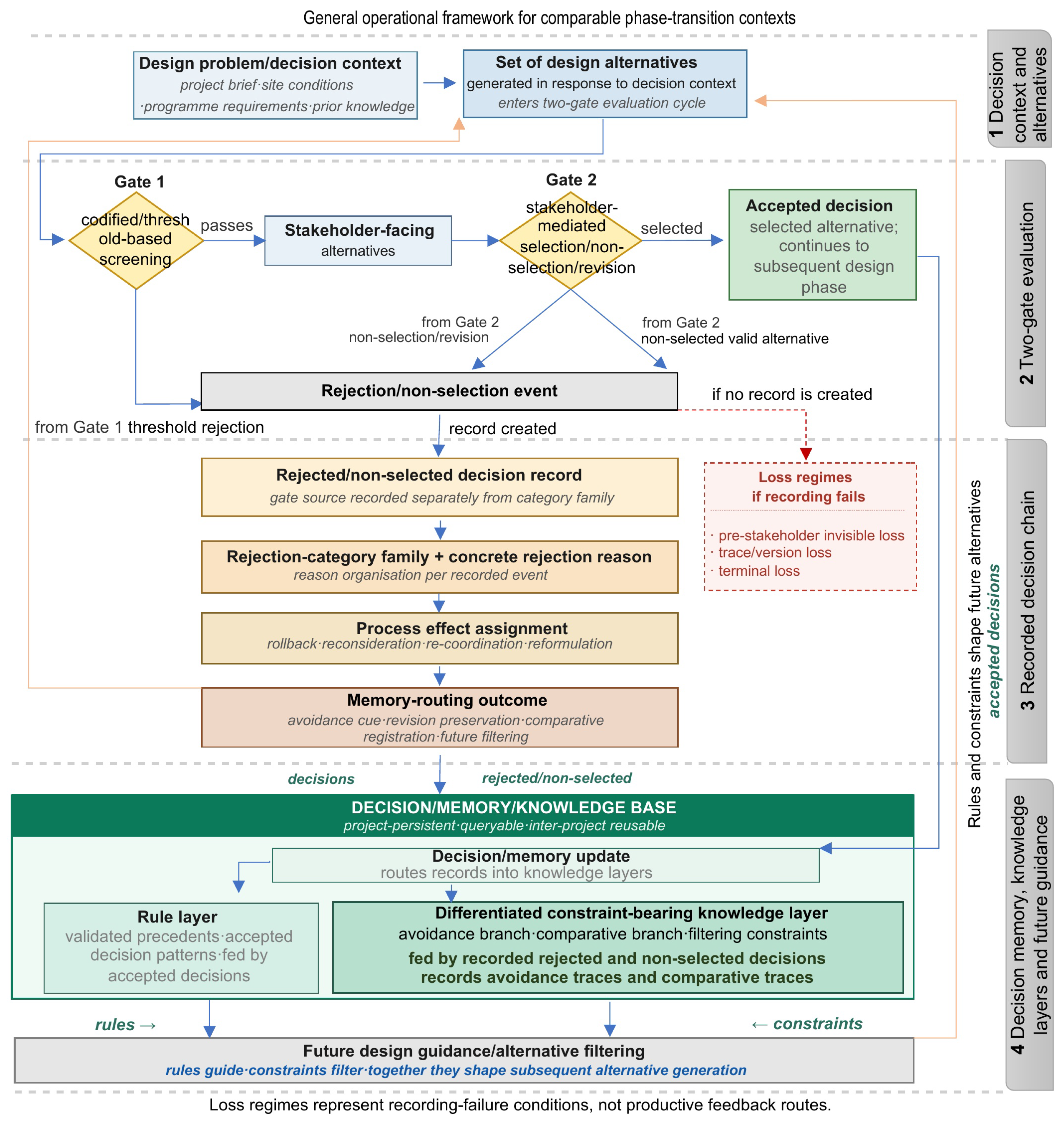
4.4. Recorded Decision Chain and Knowledge-Layer Routing

The analytical object at the centre of the model is the recorded decision trace. A rejection or non-selection event becomes reusable knowledge only when it is transformed into a structured record connecting five elements: decision status, gate source, concrete reason, process effect and memory destination. These elements form the recorded decision chain.
Decision status identifies whether an alternative was rejected at Gate 1, returned for revision at Gate 2 or left non-selected at Gate 2. Gate source locates the event procedurally; concrete reason gives the event-specific explanation linked to a category family; process effect records the design process consequence; and memory destination indicates routing into the rule layer, avoidance branch or comparative branch, or, for a revision-return event, temporary retention as a version record. The chain does not assume that learning occurs automatically; learning depends on the trace being recorded, reasoned and linked.
The decision/memory structure that receives recorded traces has two layers. The rule layer stores knowledge derived from accepted and stabilised decisions: validated precedents, accepted decision patterns and project-specific rules. The constraint-bearing knowledge layer stores rejected and non-selected decisions and is internally bifurcated. The avoidance branch stores rejected, invalidated or eliminated decisions as paths to avoid under specified conditions. The comparative branch stores valid but non-selected alternatives, preserving why one viable direction was set aside in relation to another. This bifurcation prevents valid non-selection from being read as failure while still treating it as constraint-bearing knowledge.
The two layers are connected through future design guidance. Rules from the rule layer guide subsequent alternatives by identifying validated patterns. Constraints from the constraint-bearing layer filter alternatives by indicating paths to avoid and trade-offs to anticipate. Together they shape the next round of alternative generation and evaluation.
A revision-return event is not routed to a permanent layer at the point of revision; its trace is retained as a version record under revision preservation, and the revised alternative re-enters the alternative set, reaching a knowledge layer only when it attains a terminal status.
Figure 1 maps the recording logic across comparable phase-transition contexts.

4.5. Model Components and Working Categories

The model translates the conceptual argument developed in Section 2, Section 3 and Section 4 into a structured decision/memory logic. It does not classify all possible rejection reasons; it shows how rejected and non-selected architectural decisions can be recorded, organised and routed into reusable knowledge structures. This section proceeds through four elements: model components, gate source/category family decoupling, working rejection-category families and process effect/memory-routing logic.

4.5.1. Main Components

The model is composed of three component groups: decision process components, recorded decision organisation components and knowledge-layer components. The first defines the decision context, alternatives and gate of evaluation; the second transforms rejection or non-selection events into traceable records; the third explains how these records contribute to the rule layer or the differentiated constraint-bearing knowledge layer. This structure builds on design rationale, decision documentation and design reuse research, which emphasise that reusable design knowledge depends on alternatives, reasons, constraints, context and version history rather than final outcomes alone [13,14,18,19,29]. Table 5 specifies each component, its analytical role and the information it records, transforms or links.

4.5.2. Decoupling Gate Source from Category Family

The analytical value of the two-gate logic lies in separating where a rejection or non-selection event emerges from why it occurs. Gate source records the procedural location of the event: Gate 1 for codified or threshold-based screening, and Gate 2 for stakeholder-mediated selection, non-selection or revision.
Category family records the type of reason that makes an alternative invalid, less viable or less preferable. The distinction is procedural and analytical, not an objective/subjective opposition: Gate 1 may involve professional interpretation, and Gate 2 may include explicit requirements.
This decoupling prevents a common collapse in decision documentation. A Gate 1 rejection is not necessarily only a regulatory case; it may also involve spatial, performance or technical development issues. A Gate 2 non-selection is not necessarily only a stakeholder value case; it may also involve spatial efficiency, operational preference or technical maturity. The model therefore records event location and reason type as separate but linked pieces of decision knowledge.

4.5.3. Working Rejection-Category Families

The working rejection-category families are not proposed as a universal taxonomy. They provide an organising framework for the selected phase-transition band, where spatial, regulatory, technical, operational and stakeholder considerations become increasingly interdependent. The complete family structure is provided in Appendix A.
The six working families are: regulatory/compliance-based rejections; brief, stakeholder and value-driven rejections; interdisciplinary coordination and clash-based rejections; analytical/performance insufficiency-based rejections; spatial/configurative incompatibility-based rejections; and technical development, detailing and buildability/operability insufficiency-based rejections. Information deficiency, weak representation and traceability problems are treated as cross-cutting meta-conditions rather than as a separate family, because they can affect the visibility and reuse of any rejection reason.
These families are not mutually exclusive taxonomic classes. A single rejected or non-selected decision may be assigned a primary family and, where relevant, a secondary family. Their role is to organise traces, not to close the field of possible reasons. This matters because architectural rejection events often emerge through overlapping constraints: a regulatory issue may carry spatial implications, and a stakeholder-mediated revision may reveal technical or operational insufficiency.
This positioning differentiates the model from construction change-cause taxonomies, which classify project-level causes and effects of change [38,40]. The present model works at the decision node level: it asks how a rejected or non-selected decision can be recorded, linked to a process effect and made available for future design judgement.

4.5.4. Process Effects and Memory-Routing Outcomes

A rejection-category family explains why an alternative becomes problematic or less preferable; a process effect explains what this event does to the design process. The model does not match each category family deterministically to one effect. The same family may produce different effects in different contexts, and one event may produce more than one effect.
The model distinguishes process redirection effects from memory-routing outcomes. Rollback, reconsideration, re-coordination and reformulation describe how a decision event redirects the current process. Avoidance cue, revision preservation, comparative registration and future filtering describe how the recorded trace remains useful within decision/memory. This distinction is necessary because a valid but non-selected alternative may not redirect the current design move, yet may still generate comparative filtering knowledge for future alternatives.
Four process redirection effects are used as organising terms. Rollback reopens a previously assumed or provisionally stabilised decision. Reconsideration reassesses the same decision field through different criteria, values or priorities. Re-coordination adjusts relations between actors, disciplines, systems or model elements. Reformulation reframes the decision problem or the logic of alternative generation.
Four memory-routing outcomes describe how the trace remains useful after the immediate design move. Avoidance cue stores a rejected or eliminated alternative as a path to avoid under specified conditions in the avoidance branch. Revision preservation keeps the rationale of a previous version when an alternative returns in revised form. Comparative registration stores a valid but non-selected alternative as comparison knowledge in the comparative branch. Future filtering allows recorded rejection and non-selection traces to shape later alternatives by indicating what should be avoided, reconsidered or compared.
These effects and outcomes connect rejected and non-selected decisions to future design action. Section 4.6 demonstrates this logic through a constructed hotel-floor decision node in which three alternatives exercise the three loss types introduced in Section 4.3.

4.5.5. Formal Specification of the Recording Procedure

The four components in Section 4.5 can be expressed as a single recording procedure. Algorithm 1 formalises how a decision event is captured, classified, assigned a process effect and routed into a knowledge layer. The procedure is a logical specification, not a software design: it does not evaluate alternatives or make decisions. The two-gate outcome is an input to the procedure, produced by the design team and codified checks; the procedure records and routes that outcome. Reading the algorithm against its omitted form also clarifies the three loss types of Section 4.3: each loss type is the result of the procedure not being applied to an event of the corresponding decision status.
The algorithm makes three properties of the model explicit. First, recording and routing are conditional on the procedure being applied: when it is omitted, the event does not produce neutral non-recording but a specific loss type. Second, the four decision statuses reach four distinct destinations, with revision-return held as a temporary version record rather than routed to a permanent layer. Third, the eight fields of the record are produced in a fixed order, which is what allows the query families discussed in Section 5.3 to operate across projects. The procedure is deliberately implementation-agnostic: it specifies what must be recorded and where it must be routed, not the software in which this occurs.

4.6. Demonstrative Application: Group 1 Hotel-Floor Decision Node

This section applies the model to a constructed hotel-floor decision node. The scenario is a methodological demonstration, not an empirical case study, performance test or design proposal. Its purpose is to make the model’s decision recording logic visible through three alternatives that exercise the three loss types.

4.6.1. Scenario Scope and Demonstrative Status

The selected decision node concerns the organisation of the vertical circulation core, horizontal corridor, service spaces and accommodation areas on a typical hotel floor. This field is suitable because it brings spatial organisation, regulatory screening, operational flow, service access, room efficiency priorities and stakeholder-mediated judgement into the same phase-transition context. It is also a familiar architectural problem in which comparable trade-offs recur across projects and stakeholders [29,31].
The scenario is constructed as a minimum demonstrative configuration. It uses one decision node and three alternative fates because a conceptual model must first show that its decision statuses, routing branches and loss types are internally distinguishable before empirical testing can begin. The purpose is therefore not to validate the frequency, completeness or real-world distribution of the three loss types, but to demonstrate that the recorded decision chain can distinguish early elimination, revision-return and valid non-selection within the same architectural decision context. The hotel-floor scenario is a coherence check of the model’s analytical structure, not empirical evidence.
The exact mapping between alternatives and loss types is constructed for analytical legibility; the scenario does not claim that real architectural decisions are normally distributed into three discrete fates. Its analytical value lies in showing that, when such fates occur, the model can record them through distinct decision chain pathways without conflation.
The three alternatives are not competing final design solutions; they are decision candidates selected to expose three fates. Alternative 1A is eliminated at Gate 1 before stakeholder-facing review; Alternative 1B passes Gate 1 but returns for revision after Gate 2; Alternative 1C passes Gate 1 and remains valid, but is left non-selected after stakeholder-mediated comparison. Together, they show how one decision node can produce avoidance knowledge, revision-preserved knowledge and comparative filtering knowledge.

4.6.2. Paired Comparison of Model-Applied and Counterfactual Regimes

The paired reading of Figure 2a,b matters because the model does not treat rejection as automatically producing knowledge: a decision trace must be recorded, reasoned and linked to a process effect before it enters decision/memory.

4.6.3. Alternative 1A: Gate 1 Early Elimination

Alternative 1A shifts the core away from the centre of the typical floor to tighten the room arrangement and increase apparent room efficiency. Although spatially economical at first glance, the displaced core lengthens circulation and creates combined escape route and accessibility problems during Gate 1 screening. The alternative is therefore eliminated before stakeholder-facing review, illustrating the role of codified and threshold-based checking in early design filtering [7,34].
In the model-applied condition, 1A becomes a recorded rejection. Its primary family is regulatory/compliance-based rejection, with a secondary relation to spatial/configurative incompatibility. The concrete reason is the combined escape and accessibility failure. Its process effect is re-coordination and reformulation, because the relationship between core position, corridor length, room layout and safe accessible movement must be reopened. Its memory-routing outcome is an avoidance cue for off-centre cores combined with elongated circulation under escape and accessibility thresholds.
In the counterfactual baseline, 1A becomes pre-stakeholder invisible loss. The option is removed, but the rationale remains weakly preserved or absent, allowing future teams to repeat a similar off-centre core strategy without seeing why it became untenable.

4.6.4. Alternative 1B: Gate 2 Revision-Return

Alternative 1B uses a central core, places the service package close to the core and maintains a more balanced room efficiency logic. It passes Gate 1 because it does not breach codified or threshold-based screening conditions. At Gate 2, however, stakeholder-mediated review identifies problems in service operability and operating flow. The issue is not terminal rejection; the alternative returns for revision, consistent with the literature on requirements, briefing and coordination-driven redirection [8,10,31,32].
Alternative 1B becomes a revision-return record. Its category assignment is co-primary: brief/stakeholder/value-driven rejection and technical development/buildability–operability insufficiency. The concrete reason is insufficient operating flow and service operability. Its process effect is reconsideration and reformulation, because service circulation, room service relations and the service package must be revised. Its memory-routing outcome is revision preservation, which retains the previous version rationale.
In the counterfactual baseline, 1B becomes trace/version loss. The revised version remains, but the previous version rationale depends on fragmented memory, weakening the version history needed for future understanding and reuse [19]. In this scenario, the accepted path is the revised version of 1B following Gate 2 reconsideration.

4.6.5. Alternative 1C: Recorded Non-Selection of a Valid Alternative

Alternative 1C also passes Gate 1. It provides wider corridors and a stronger user comfort profile, but reduces room efficiency. It is technically valid and not rejected as wrong or non-compliant. At Gate 2, it is left non-selected because another option is preferred within the trade-off between spatial comfort, room efficiency and operational priorities. Although Figure 2a places 1C under a spatial/configurative heading for visual brevity, the model treats this case as comparative non-selection rather than rejection in the strict sense.
This alternative is critical because it should not be treated as negative knowledge. Its primary family is spatial/configurative incompatibility-based non-selection, but its epistemic role differs from 1A. The concrete reason is that the corridor/room relationship weakens plan efficiency in relation to the selected direction. Its memory-routing outcome is comparative registration and future filtering.
Alternative 1C enters the comparative branch of the constraint-bearing knowledge layer. The record preserves why a valid option was left non-selected and can support future decisions when a similar comfort/efficiency trade-off recurs. This aligns with design decision research showing that used and rejected alternatives both reveal design process structure [26]. In the counterfactual baseline, 1C becomes terminal loss: a valid but non-selected alternative disappears without a comparison trace or filtering cue.

4.6.6. Decision Trace Specimen

Table 6 presents the decision trace counterpart of Figure 2a,b, showing how each alternative is recorded through gate status, category and concrete reason, process effect and memory-routing outcome.

4.6.7. Practitioner-Informed Recognisability Note

This subsection is not presented as empirical validation, project document analysis or participant-based evidence. It is an anonymised practitioner-informed recollection by the first author, included to clarify the practical recognisability of the loss patterns developed conceptually in the model.
The recollection concerns professional participation in a multi-storey hotel project developed under a corporate brand design guide. The guide specified minimum room areas, mandatory spatial content and circulation standards, and therefore functioned as a codified pre-screening regime that framed alternative generation before any client-facing review. Its requirements acted as threshold conditions determining which configurations could be advanced for stakeholder evaluation, illustrating that Gate 1 screening may be driven by brand and brief standards, not only by statutory codes.
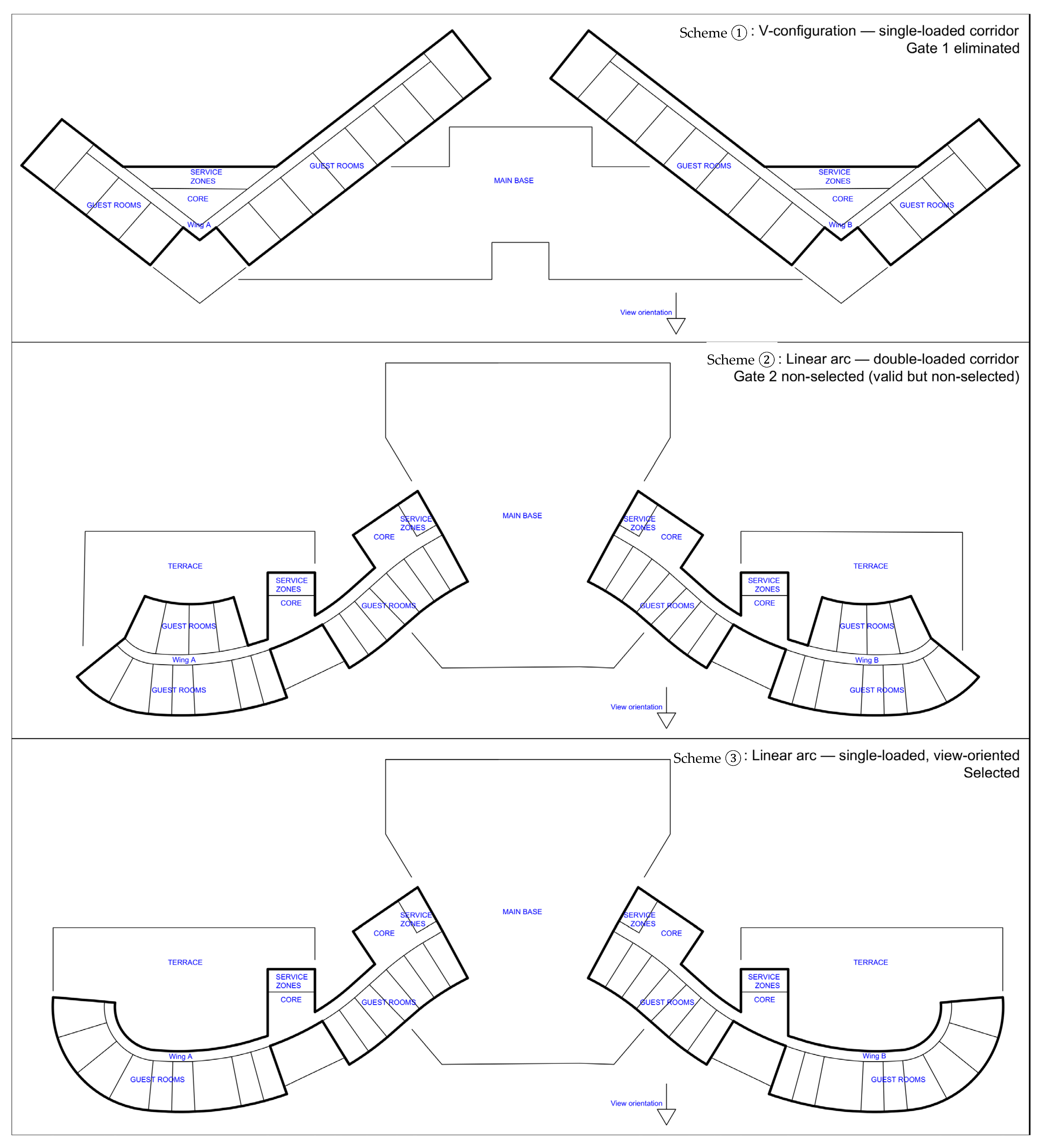
During schematic design, three typical-floor configurations were generated. A V-configuration with two wings and a central core was eliminated before client review, because the V-arm geometry weakened guest wayfinding and the central core could not provide balanced service access to both wings, a geometric constraint that conflicted with the corporate circulation standard. The decision was not recorded as a rationale-bearing event; the working files were archived without an explicit reason trace, leaving the eliminating conditions invisible to any later team. This corresponds to the pre-stakeholder invisible loss described in Section 4.3.
Two linear arc configurations were subsequently advanced for stakeholder evaluation: a double-loaded corridor arrangement and a single-loaded, view-oriented corridor arrangement. The single-loaded configuration was preferred on the grounds of guest room orientation and view quality. The double-loaded arrangement was set aside as valid but non-selected; the comparative basis for setting it aside was not systematically recorded. This corresponds to terminal loss: a valid alternative disappeared without a comparison trace that could support future decisions when a similar corridor-loading trade-off recurs.
A reopening of the room arrangement decision was later discussed, allowing terrace-facing rooms to be considered, but the discussion was never resolved into a recorded decision or carried into a revised draft. When the question resurfaced, no trace of the earlier deliberation remained and the reasoning had to be reconstructed from memory. This corresponds to trace/version loss.
Figure 3 provides an anonymised schematic reconstruction of the three configurations referred to in this note.
These recollections do not validate the frequency, completeness or generalisability of the three loss types. They support their practical recognisability and clarify why a lightweight decision record template may be useful in BIM/CDE-supported workflows, where rejected, revised and valid but non-selected alternatives can otherwise remain outside the formal project memory.

5. Discussion

The model has been developed as a conceptual/analytical model for organising rejected and non-selected architectural design decisions. This section discusses its epistemic, methodological and practical implications, then clarifies its limitations and transferability beyond the demonstrated hotel-floor decision node.

5.1. Epistemic Implications for Architectural Design Knowledge

The model reframes rejected and non-selected architectural decisions as epistemically significant traces of design judgement. Its central implication is that architectural knowledge is carried not only by final outcomes but also by the alternatives through which problems are framed, tested, redirected and compared. A rejected alternative is not simply an abandoned option; it may record where a misfit emerged, which assumptions became untenable and which constraints redirected the process.
The model also sharpens the relationship between rejection and negative knowledge. Negative knowledge applies most clearly to rejected, invalidated or eliminated decisions that enter the avoidance branch. Valid but non-selected alternatives have a different status: they generate comparative filtering knowledge by preserving why one viable direction was set aside in relation to another. The avoidance/comparative bifurcation therefore prevents valid non-selection from being misread as failure and allows architectural design memory to retain heterogeneous forms of constraint-bearing knowledge.

5.2. Methodological Implications for Decision/Memory Modelling

The first methodological implication is that decision/memory loss is not a single phenomenon. Pre-stakeholder invisible loss, trace/version loss and terminal loss show that what disappears depends on the alternative’s procedural position and decision status. These are not productive learning routes, but failure conditions created by weak or absent recording. The model therefore makes the decision/memory gap more precise by linking each loss type to a specific vulnerability in the design process.
The second implication concerns the decoupling of gate source from category family. The model does not assume that every Gate 1 rejection is regulatory or that every Gate 2 non-selection is stakeholder-driven. Instead, it records where the event occurs and why it occurs as separate but linked elements. This preserves the mixed character of architectural judgement, where compliance, spatial fit, operational value, technical development and stakeholder preference often intersect.
The third implication is the distinction between process redirection effects and memory-routing outcomes. This allows the model to handle alternatives that do not redirect the current design process but still generate memory value. Alternative 1C is the clearest case: it produces no immediate process redirection at Gate 2, yet it generates comparative filtering knowledge for future alternatives. Without this distinction, the model would miss decisions that carry memory value but do not redirect the current process.

5.3. Practical Implications: BIM, CDE and Design Review Records

The practical value of the model lies in structuring decisions that already occur in architectural design processes; it does not require a new software platform. Zahedi et al. [14] show how design episodes, explanation tags and constraints can preserve design intent across BIM workflows, while Wyke and Munch Lindhard [24] note the inconsistent recording of design rationale in AEC documentation. The model extends rather than replaces such practices by adding an epistemic ordering: separating avoidance traces from comparative traces at the level of decision events. The minimum record preserves gate source, decision status, concrete reason, process effect and memory destination.
The practical record is intentionally limited. It does not ask design teams to document every discussion, but to preserve the decision traces most vulnerable to loss: alternatives rejected before stakeholder visibility, alternatives returned for revision and valid options left non-selected. Table 7 presents the eight-field structure as a fillable recording instrument for these traces within BIM, CDE and design review workflows.
The eight fields constitute the minimum set required for a record to function within the decision chain developed in Section 4.4, expanding the five relational elements of this chain into operational fields. Presented here as a fillable instrument, the structure extends the recording protocol beyond the constructed scenario. It is not a software interface and makes no claim to implementation in a specific BIM or CDE platform. The fields specify what should be retained when a rejected, revision-return or valid but non-selected alternative is recorded; how those fields are captured in a given platform is an implementation choice set out later in this section. The template can serve as a design review form, a BIM issue supplement, a CDE comment structure or a retrospective coding instrument for future validation studies.
The template is designed for project actors with existing responsibility for design review, BIM/CDE coordination or decision documentation: BIM managers, design coordinators, project architects or technical design leads. It is intended to be integrated into established coordination routines rather than to function as a standalone form, and is not intended for unsupervised use by novice recorders; consistent application depends on direct knowledge of the decision event, on recording the concrete reason before assigning the family label, and on careful primary/secondary distinction. It is a recording instrument, not a validated tool; naturalistic validation constitutes the next research step, formalised as RA4.
From an implementation perspective, the recording procedure formalised in Algorithm 1 and the eight-field template it produces are compatible with existing BCF and CDE coordination structures at the level of metadata mapping [2,3,51].
In a BCF-based issue workflow, decision context can be linked to the topic title and description; gate source, decision status, category family and memory-routing outcome can be represented through controlled labels, status values or custom classifications; concrete reason and process effect can be recorded in the issue description or comment thread; and cross-references can be linked to model viewpoints, elements, documents or related topics. In a CDE environment, the same record can be associated with information containers, revision codes, status codes and review comments, in line with ISO 19650 information management conventions. This article does not claim that this mapping has been implemented or validated in a specific BCF-based or CDE-based software platform; rather, it identifies a practical route through which the proposed decision/memory record could be operationalised within existing BIM and information management workflows.
The template also enables query types that general-purpose decision documentation rarely supports. The following queries are expressed in plain English so that the protocol remains implementation-agnostic, adaptable to BIM issue trackers, CDE comment threads or design review minutes.
Three query families are particularly relevant. Avoidance retrieval queries return rejected alternatives by gate source and category family, for example, alternatives rejected at Gate 1 with regulatory/compliance-based primary family in comparable projects. Comparative retrieval queries return valid but non-selected alternatives by decision context, asking which viable alternatives were set aside and on what comparative basis. Process effect queries return decision events by their procedural consequence, such as Gate 2 revision-return events that triggered re-coordination. Together, these query families support early screening, comparative reasoning and process-level learning across projects.
The Example column of Table 7 already applies the eight-field structure to Alternatives 1A, 1B and 1C from the demonstrative scenario, and the query families above operate over records of this form. Each completed record connects a rejection event as a single trace: gate source identifies procedural origin, category family and concrete reason organise the explanation, process effect identifies redirection, and memory-routing outcome locates the trace within the constraint-bearing knowledge layer. In practice, each field may be expanded with project-specific cross-references or contextual notes.

5.4. Limitations and Construct Validity Boundaries

The model has five acknowledged limitations. It is a conceptual/analytical contribution and has not been validated through real project archives, design review datasets or BIM issue logs. The Section 4.6 scenario is a constructed minimum configuration rather than a real case. The working rejection-category families in Appendix A are illustrative rather than taxonomically closed. The model is calibrated for the transition from spatial coordination to technical design and may need adaptation for other phases. Finally, the recording protocol assumes that design teams have, or can develop, the institutional capacity to capture decisions at a lightweight level, which may vary across practice contexts. This capacity is not only technical but also sociotechnical. Documenting rejected decisions may be discouraged by blame cultures, fear of failure, reputational risk or contractual sensitivity; it may also be constrained by user adoption, the additional documentation effort placed on design teams, and the information management requirements of integrating decision records into existing BIM and CDE workflows. These barriers require empirical investigation before the protocol can be treated as routine practice.
A construct validity boundary also follows from the relationship between the model and the demonstrative scenario. The scenario was designed to make the three loss types visible within a single decision node, which produces a clean but potentially artificial mapping between alternatives and loss types. Actual project archives are likely to contain mixed cases, partial losses and overlapping conditions. The constructed configuration is therefore useful for exposing the model’s analytical structure, but it cannot test how the model behaves in real project ecologies.
The practitioner recollection presented in Section 4.6.7 reflects a single retrospective account by the first author. It is not corroborated through interviews with other project participants, document analysis or independent recall validation. Its function is illustrative rather than evidential.
A possible objection is that classical design rationale frameworks such as DRL, IBIS and QOC already capture trade-offs between options through arguments, criteria and positions [11,12,13], making comparative filtering knowledge a relabelling rather than a new construct. The response is that these frameworks generally treat non-selected options within the same argumentative space, whereas the present model distinguishes rejection from valid non-selection at the level of memory routing. Its contribution is not to record more rationale, but to bifurcate the constraint-bearing knowledge layer so that comparative filtering knowledge can be retrieved without being conflated with avoidance knowledge. It is therefore an organisational and epistemic refinement of design rationale, not a substitute for it.

5.5. Transferability Beyond the Demonstrated Band

The model is transferable in a controlled sense. Although developed within architectural design research and demonstrated through a hotel-floor decision node, its logic may apply to other architectural situations where spatial alternatives encounter regulatory, technical, operational and stakeholder-mediated constraints. Comparable decision nodes can be identified in building types such as schools, hospitals, housing and mixed-use projects, as well as in interior planning, façade strategy and structural/spatial coordination. Transferability concerns the recording logic, avoidance/comparative bifurcation and gate source/category family decoupling, not the fixed transfer of the specific working families in Appendix A. Because Algorithm 1 specifies this recording logic in implementation-agnostic terms, taking the two-gate outcome as an input rather than computing it, the procedure itself is transferable: adapting the model to another phase or building type requires recalibrating the category families and gate criteria, not rewriting the recording-and-routing procedure.
The transferability claim is also bounded. The model may need recalibration for earlier programming phases, where alternatives are more loosely defined, or for later detailing phases, where alternatives are constrained by previously stabilised decisions. Practice frameworks outside the RIBA system require equivalent identification of phase-transition bands, and the two-gate logic should be read as analytical rather than as a one-to-one mapping to any stage-gate procedure. These boundaries define the conditions of the model’s analytical usefulness.

6. Conclusions

This article has developed a conceptual/analytical model for organising rejected and non-selected architectural design decisions within the transition from spatial coordination to technical design. The model is positioned as a conceptual/analytical model with typological building blocks, rather than as a predictive theory, empirical study or software platform. Its central proposition is that rejected and non-selected alternatives become epistemically valuable when they are recorded as decision traces and routed through a differentiated knowledge structure that distinguishes accepted decisions, avoidance traces and comparative filtering knowledge. This article thereby addresses the bias of architectural design memory towards what was accepted.
Four contributions follow. First, the typology of pre-stakeholder invisible loss, trace/version loss and terminal loss makes the differential vulnerability of design alternatives visible across the decision process. Second, the decoupling of gate source from category family separates where an event occurs from why it occurs, preserving the mixed character of architectural judgement. Third, the bifurcation of the constraint-bearing knowledge layer into avoidance and comparative branches allows rejected and valid but non-selected decision knowledge to be retained without being conflated. Fourth, the recording protocol, operationalised through the eight-field decision record template and minimum query specification, provides a practical structure for making these traces retrievable within BIM, CDE and design review workflows.
This article also opens four directions for empirical extension.
RA1 (Empirical distribution of loss types).
How are the three loss types distributed across real architectural project archives? Methods may include analysis of BIM issue logs, design review minutes, coordination records and CDE comment threads, supported where appropriate by observation of decision events.
RA2 (Comparative filtering knowledge reuse).
Do recorded comparative filtering traces reduce repeat misfits across successive projects within a firm? Methods may include longitudinal studies tracking comparable decision contexts across multiple projects.
RA3 (Procurement and process variability).
How does the two-gate structure transform under different procurement and delivery regimes, such as traditional, design/build, integrated project delivery or public/private partnership? Methods may include comparative case studies across procurement contexts.
RA4 (CDE-embedded recording and face validation).
Can the minimum decision record template be embedded in existing CDE workflows without producing additional documentation overhead, and do experienced practitioners recognise the eight-field structure as a usable recording instrument? Methods may include face validation workshops with BIM managers, design coordinators and practising architects, followed by follow-up interviews on organisational fit and, where feasible, design science action research with architectural practice partners.
The model proposed in this article remains conceptual/analytical and has not yet been validated through real project data, BIM manager evaluation or retrospective CDE/BCF analysis. Its immediate next research step is therefore naturalistic validation, formalised in RA4 through BIM manager face validation, retrospective testing on completed project records, or a combination of the two.
Architectural design memory remains, in many documentation practices, biased towards what was accepted. The model proposed here argues that this bias is neither inevitable nor analytically justified. Rejected and non-selected decisions carry traces of how the design problem was framed, where misfits appeared and which alternatives were viable but not preferred. When these traces are recorded with their gate source, concrete reason, process effect and memory destination, they become available as cumulative architectural knowledge. The contribution of this article is therefore not to close a question, but to open one for architectural design research and practice: how can the discipline systematically recover the design knowledge that lies in what was not built?

Author Contributions

Conceptualisation, K.Ö. and M.H.Ö.; methodology, K.Ö.; formal analysis, K.Ö.; investigation, K.Ö. and M.H.Ö.; resources, K.Ö. and M.H.Ö.; writing—original draft preparation, K.Ö.; writing—review and editing, K.Ö. and M.H.Ö.; visualisation, K.Ö.; supervision, K.Ö.; project administration, K.Ö. All authors have read and agreed to the published version of the manuscript.

Funding

This research received no external funding.

Institutional Review Board Statement

Not applicable. This study did not involve human participants, animal subjects, third-party informants, or institutional data requiring ethical review. The practitioner-informed note in Section 4.6.7 reflects the first author’s own anonymised professional recollection and does not constitute participant-based research.

Informed Consent Statement

Not applicable. No human participants were involved in this study.

Data Availability Statement

The original contributions presented in this study are included in the article. Further inquiries can be directed to the corresponding author.

Acknowledgments

The authors thank colleagues in architectural and BIM-related research, and practising architects and BIM coordinators in the first author’s professional network, for the conceptual feedback that contributed to the development of this model. During the preparation of this manuscript, the authors used Claude Opus 4.7 (Anthropic PBC, San Francisco, CA, USA) for language refinement and structural feedback on draft sections. The authors have reviewed and edited the output and take full responsibility for the content of this publication.

Conflicts of Interest

The authors declare no conflicts of interest.

Abbreviations

The following abbreviations are used in this manuscript:
AECArchitecture, Engineering and Construction
BCFBIM Collaboration Format
BIMBuilding Information Modelling
CDECommon Data Environment
RIBARoyal Institute of British Architects

Appendix A

Table A1. Working rejection-category families for the spatial coordination-to-technical design band.
No.Rejection-Category FamilyScopeLiterature Citation(s)Typical Concrete Rejection/Non-Selection Reason ExamplesCharacteristic Rejection Generation LogicPrincipal Involved Actor(s)
1Regulatory/compliance-based rejectionsCovers cases in which design alternatives are rejected or eliminated because they fail to satisfy applicable regulations, codes, standards or formal compliance requirements.Eastman et al. [7]; Dimyadi et al. [34]; Donath and González Böhme [35]; RIBA [46].Failure to meet escape route distance or evacuation requirements; failure to satisfy accessibility criteria; incompatibility with planning conditions, setbacks, height limits or floor-area restrictions; failure to satisfy mandatory minimum area or capacity requirements; non-compliance with codified circulation, stair, ramp, lift or safety-zone requirements.Compliance check decisive; interpretation/approval component complementary.Architect; relevant engineer(s); where necessary, code or authority consultant.
2Brief/stakeholder/value-driven rejectionsCovers cases in which design alternatives are rejected, returned for revision or left non-selected because they are inconsistent with the brief, stakeholder expectations, user/operator needs or value priorities.Yu et al. [31]; Sahadevan and Varghese [32]; Baldauf et al. [33]; Chachere and Haymaker [47].Incompatibility with the client’s target room count, room type distribution or capacity expectations; inconsistency with operational scenarios, service flow or operational efficiency expectations; failure to meet user/guest experience, access comfort or spatial quality expectations; conflict with the value, brand or concept expectations defined in the project brief; rejection or non-selection due to priority conflicts among stakeholders.Stakeholder-mediated evaluation decisive; brief/value criteria guiding.Client; architect; operator/user representative; where relevant, investor or brand representative.
3Interdisciplinary coordination/clash-based rejectionsCovers cases in which design alternatives are rejected or returned for revision because of coordination problems or clashes between architectural, structural, mechanical, electrical or other disciplinary systems.Wang and Leite [10]; Mehrbod et al. [9]; Akponeware and Adamu [36]; Jacobsson and Merschbrock [37].Conflict between service routes and structural or architectural volumes; incompatibility between shafts, risers or service voids and the architectural plan; insufficient maintenance access to building services; unresolved layout tensions between the architectural core, structural system and service systems; revision or reconsideration required due to physical, procedural or model-based coordination issues.Coordination check decisive; interdisciplinary resolution complementary.Architect; structural engineer(s); building services engineer(s); design coordination team.
4Analytical/performance insufficiency-based rejectionsCovers cases in which design alternatives are rejected or returned for revision because they fail to meet structural, environmental, functional or operational performance targets during analysis and evaluation.Pauwels et al. [48]; Chachere and Haymaker [47]; Eastman et al. [7]; RIBA [46].Failure to meet structural span, load or stability requirements; insufficient energy, daylight, thermal comfort or sustainability performance; inadequate acoustic, circulation or occupancy density performance; failure to satisfy service capacity or operational performance expectations; analysis results indicating inconsistency between the alternative and the project’s performance targets.Analysis/evaluation decisive; expert interpretation complementary.Architect; relevant engineer(s); analysis/evaluation team; where necessary, sustainability or performance consultant.
5Spatial/configurative incompatibility-based rejectionsCovers cases in which design alternatives are rejected, returned for revision or left non-selected because of incompatibility or relative weakness in plan organisation, spatial configuration, geometric layout or functional configurative relations.Cooper et al. [29]; Pauwels et al. [48]; Seebohm and Wallace [49]; RIBA [46].Room, corridor, service and shared-area relationships weakening functional flow; core placement disrupting plan organisation; room type distribution or floor plan configuration conflicting with the operational scenario; spatial tension between service areas and user areas; geometric layout remaining inefficient in terms of orientation, access or area use.Spatial-fit reading decisive; brief/functional evaluation complementary.Architect; design team; client/operator representative.
6Technical development/detailing/buildability–operability insufficiency-based rejectionsCovers cases in which design alternatives are rejected or returned for revision because they do not reach an adequate level of technical development and detailing, or because they fail to satisfy buildability and operability requirements.Jallow et al. [8]; Zahedi et al. [14]; Wang and Leite [10]; Mehrbod et al. [9]; RIBA [46].Technical solution not sufficiently mature to proceed into technical design; insufficient development for fabrication, assembly or site implementation; failure to satisfy maintenance, access or operability requirements; service and technical spaces not meeting actual sizing, access or installation needs; need for further development based on specialist consultant, contractor or technical team input.Technical resolution assessment decisive; buildability/operability interpretation complementary.Architect; relevant engineer(s); specialist consultant or technical team; where necessary, contractor or specialist subcontractor.
Note. The families and concrete rejection/non-selection reason examples presented in this appendix do not claim to form a complete or universal taxonomy. They provide an illustrative and organising working framework for the defined phase-transition band. The family set may be extended, reduced or reconfigured according to project context. “Information deficiency/weak representation/traceability problem” is treated not as an independent family, but as a cross-cutting meta-condition across all families.

References

  1. Borkowski, A.S. A literature review of BIM definitions: Narrow and broad views. Technologies 2023, 11, 176. [Google Scholar] [CrossRef]
  2. ISO 19650-1:2018; Organization and Digitization of Information About Buildings and Civil Engineering Works, Including Building Information Modelling (BIM)—Information Management Using Building Information Modelling—Part 1: Concepts and Principles. International Organization for Standardization: Geneva, Switzerland, 2018.
  3. ISO 19650-2:2018; Organization and Digitization of Information About Buildings and Civil Engineering Works, Including Building Information Modelling (BIM)—Information Management Using Building Information Modelling—Part 2: Delivery Phase of the Assets. International Organization for Standardization: Geneva, Switzerland, 2018.
  4. Schön, D.A. The Reflective Practitioner: How Professionals Think in Action; Basic Books: New York, NY, USA, 1983. [Google Scholar]
  5. Cross, N. Designerly ways of knowing. Des. Stud. 1982, 3, 221–227. [Google Scholar] [CrossRef]
  6. Rittel, H.W.J.; Webber, M.M. Dilemmas in a general theory of planning. Policy Sci. 1973, 4, 155–169. [Google Scholar] [CrossRef]
  7. Eastman, C.; Lee, J.-M.; Jeong, Y.-S.; Lee, J.-K. Automatic rule-based checking of building designs. Autom. Constr. 2009, 18, 1011–1033. [Google Scholar] [CrossRef]
  8. Jallow, A.K.; Demian, P.; Baldwin, A.N.; Anumba, C.J. An empirical study of the complexity of requirements management in construction projects. Eng. Constr. Archit. Manag. 2014, 21, 505–531. [Google Scholar] [CrossRef]
  9. Mehrbod, S.; Staub-French, S.; Mahyar, N.; Tory, M. Beyond the clash: Investigating BIM-based building design coordination issue representation and resolution. J. Inf. Technol. Constr. 2019, 24, 33–57. [Google Scholar]
  10. Wang, L.; Leite, F. Formalized knowledge representation for spatial conflict coordination of mechanical, electrical and plumbing systems in new building projects. Autom. Constr. 2016, 64, 20–26. [Google Scholar] [CrossRef]
  11. Conklin, E.J.; Burgess Yakemovic, K.C. A process-oriented approach to design rationale. Hum. Comput. Interact. 1991, 6, 357–391. [Google Scholar]
  12. Lee, J. Design rationale systems: Understanding the issues. IEEE Expert 1997, 12, 78–85. [Google Scholar] [CrossRef]
  13. Tang, A.; Babar, M.A.; Gorton, I.; Han, J. A survey of architecture design rationale. J. Syst. Softw. 2006, 79, 1792–1804. [Google Scholar] [CrossRef]
  14. Zahedi, A.; Abualdenien, J.; Petzold, F.; Borrmann, A. BIM-based design decisions documentation using design episodes, explanation tags, and constraints. J. Inf. Technol. Constr. 2022, 27, 756–780. [Google Scholar] [CrossRef]
  15. Argyris, C. Teaching smart people how to learn. Harv. Bus. Rev. 1991, 69, 99–109. [Google Scholar]
  16. Gartmeier, M.; Bauer, J.; Gruber, H.; Heid, H. Negative knowledge: Understanding professional learning and expertise. Vocat. Learn. 2008, 1, 87–103. [Google Scholar] [CrossRef]
  17. Lyytinen, K.; Robey, D. Learning failure in information systems development. Inf. Syst. J. 1999, 9, 85–101. [Google Scholar] [CrossRef]
  18. Demian, P.; Fruchter, R. An ethnographic study of design knowledge reuse in the architecture, engineering and construction industry. Res. Eng. Des. 2006, 16, 184–195. [Google Scholar] [CrossRef]
  19. Demian, P.; Fruchter, R. Effective visualisation of design versions: Visual storytelling for design reuse. Res. Eng. Des. 2009, 19, 193–204. [Google Scholar] [CrossRef]
  20. Konda, S.; Monarch, I.; Sargent, P.; Subrahmanian, E. Shared memory in design: A unifying theme for research and practice. Res. Eng. Des. 1992, 4, 23–42. [Google Scholar] [CrossRef]
  21. Lee, J.; Lai, K.-Y. What’s in design rationale? Hum. Comput. Interact. 1991, 6, 251–280. [Google Scholar]
  22. Moran, T.P.; Carroll, J.M. (Eds.) Design Rationale: Concepts, Techniques, and Use; Lawrence Erlbaum Associates: Mahwah, NJ, USA, 1996. [Google Scholar]
  23. Bracewell, R.; Wallace, K.; Moss, M.; Knott, D. Capturing design rationale. Comput. Aided Des. 2009, 41, 173–186. [Google Scholar] [CrossRef]
  24. Wyke, S.; Munch Lindhard, S. Understanding design rationale and intent through natural language processing analysis: A search for consensus. J. Inf. Technol. Constr. 2025, 30, 631–649. [Google Scholar] [CrossRef]
  25. Siddharth, L.; Chakrabarti, A.; Ranganath, R. Modeling and structuring design rationale to enable knowledge reuse. Syst. Eng. 2020, 23, 294–311. [Google Scholar] [CrossRef]
  26. Ensici, A.; Badke-Schaub, P.; Bayazıt, N.; Lauche, K. Used and rejected decisions in design teamwork. CoDesign 2013, 9, 113–131. [Google Scholar] [CrossRef]
  27. Kamara, J.M.; Augenbroe, G.; Anumba, C.J.; Carrillo, P.M. Knowledge management in the architecture, engineering and construction industry. Constr. Innov. 2002, 2, 53–67. [Google Scholar] [CrossRef]
  28. McMahon, C.; Lowe, A.; Culley, S. Knowledge management in engineering design: Personalisation and codification. J. Eng. Des. 2004, 15, 307–325. [Google Scholar] [CrossRef]
  29. Cooper, G.S.; Cerulli, C.; Lawson, B.R.; Peng, C.; Rezgui, Y. Tracking decision-making during architectural design. J. Inf. Technol. Constr. 2005, 10, 125–139. [Google Scholar]
  30. Sobek, D.K., II; Ward, A.C.; Liker, J.K. Toyota’s principles of set-based concurrent engineering. Sloan Manag. Rev. 1999, 40, 67–83. [Google Scholar]
  31. Yu, A.T.W.; Shen, Q.; Kelly, J.; Hunter, K. An empirical study of the variables affecting construction project briefing/architectural programming. Int. J. Proj. Manag. 2007, 25, 198–212. [Google Scholar] [CrossRef]
  32. Sahadevan, V.; Varghese, K. Stakeholder value evolution, capture and assessment in AEC project design. In Proceedings of the 26th Annual Conference of the International Group for Lean Construction, Chennai, India, 18–20 July 2018; pp. 549–559. [Google Scholar] [CrossRef]
  33. Baldauf, J.P.; Formoso, C.T.; Tzortzopoulos, P.; Miron, L.I.G.; Soliman-Junior, J. Using building information modelling to manage client requirements in social housing projects. Sustainability 2020, 12, 2804. [Google Scholar] [CrossRef]
  34. Dimyadi, J.; Clifton, C.; Spearpoint, M.; Amor, R. Regulatory knowledge encoding guidelines for automated compliance audit of building engineering design. In Computing in Civil and Building Engineering 2014; Issa, R.R., Flood, I., Eds.; American Society of Civil Engineers: Reston, VA, USA, 2014; pp. 536–543. [Google Scholar] [CrossRef][Green Version]
  35. Donath, D.; González Böhme, L.F. Constraint-based design in participatory housing planning. Int. J. Archit. Comput. 2008, 6, 97–117. [Google Scholar] [CrossRef]
  36. Akponeware, A.O.; Adamu, Z.A. Clash detection or clash avoidance? An investigation into coordination problems in 3D BIM. Buildings 2017, 7, 75. [Google Scholar] [CrossRef]
  37. Jacobsson, M.; Merschbrock, C. BIM coordinators: A review. Eng. Constr. Archit. Manag. 2018, 25, 989–1008. [Google Scholar] [CrossRef]
  38. Sun, M.; Meng, X. Taxonomy for change causes and effects in construction projects. Int. J. Proj. Manag. 2009, 27, 560–572. [Google Scholar] [CrossRef]
  39. Clarkson, P.J.; Simons, C.; Eckert, C. Predicting change propagation in complex design. J. Mech. Des. 2004, 126, 788–797. [Google Scholar] [CrossRef]
  40. Birgonul, Z.; Budayan, C.; Koc, K. Development of a taxonomy for causes of changes in construction projects. Buildings 2024, 14, 278. [Google Scholar] [CrossRef]
  41. Conklin, J.; Begeman, M.L. gIBIS: A hypertext tool for exploratory policy discussion. ACM Trans. Off. Inf. Syst. 1988, 6, 303–331. [Google Scholar] [CrossRef]
  42. MacLean, A.; Young, R.M.; Bellotti, V.M.E.; Moran, T.P. Questions, options, and criteria: Elements of design space analysis. Hum. Comput. Interact. 1991, 6, 201–250. [Google Scholar]
  43. Jaakkola, E. Designing conceptual articles: Four approaches. AMS Rev. 2020, 10, 18–26. [Google Scholar] [CrossRef]
  44. Venable, J.; Pries-Heje, J.; Baskerville, R. FEDS: A framework for evaluation in design science research. Eur. J. Inf. Syst. 2016, 25, 77–89. [Google Scholar] [CrossRef]
  45. Cash, P.; Daalhuizen, J.; Hekkert, P. Evaluating the efficacy and effectiveness of design methods: A systematic review and assessment framework. Des. Stud. 2023, 88, 101204. [Google Scholar] [CrossRef]
  46. RIBA. RIBA Plan of Work 2020 Overview; Royal Institute of British Architects: London, UK, 2020; Available online: https://www.architecture.com/knowledge-and-resources/resources-landing-page/riba-plan-of-work (accessed on 10 May 2026).
  47. Chachere, J.M.; Haymaker, J.R. Framework for Measuring Rationale Clarity of AEC Design Decisions; CIFE Technical Report No. 177; Center for Integrated Facility Engineering, Stanford University: Stanford, CA, USA, 2008; Available online: https://purl.stanford.edu/fm497vr4971 (accessed on 10 May 2026).
  48. Pauwels, P.; Strobbe, T.; De Meyer, R. Analysing how constraints impact architectural decision-making. Int. J. Des. Sci. Technol. 2015, 21, 83–111. [Google Scholar]
  49. Seebohm, T.; Wallace, W. Rule-based representation of design in architectural practice. Autom. Constr. 1998, 8, 73–85. [Google Scholar] [CrossRef]
  50. Dorst, K.; Cross, N. Creativity in the design process: Co-evolution of problem-solution. Des. Stud. 2001, 22, 425–437. [Google Scholar] [CrossRef]
  51. buildingSMART International. BIM Collaboration Format (BCF). Available online: https://technical.buildingsmart.org/standards/bcf/ (accessed on 10 May 2026).
Figure 1. Swimlane process map of the proposed decision/memory recording logic across comparable phase-transition contexts. Loss regimes represent recording-failure conditions, not productive feedback routes.
Buildings 16 02332 g001
Figure 2. (a) Model-applied condition: registered learning regime in the Group 1 hotel-floor decision node. Rejected and non-selected alternatives are recorded, assigned to category/reason and process effect structures, and routed into the rule layer and the differentiated constraint-bearing knowledge layer. Alternative 1C is shown under a spatial and configurative heading for visual brevity; in the model’s terminology this represents comparative non-selection rather than threshold rejection. (b) Counterfactual condition: baseline without systematic recording in the Group 1 hotel-floor decision node. In the absence of recording, rejected and non-selected alternatives produce pre-stakeholder invisible loss, trace/version loss and terminal loss; no reusable decision/memory or cumulative design guidance is constituted.
Buildings 16 02332 g002aBuildings 16 02332 g002b
Figure 3. Anonymised schematic reconstruction of typical-floor configuration alternatives referred to in Section 4.6.7. Scheme ① shows the V-configuration eliminated at Gate 1 (codified screening); schemes ② and ③ show the two linear arc configurations advanced to stakeholder evaluation at Gate 2, of which scheme ② (double-loaded corridor) was set aside as valid but non-selected and scheme ③ (single-loaded, view-oriented corridor) was selected. The figure is not a project drawing, measured plan or BIM export; it is an anonymised schematic used solely to illustrate the decision/memory patterns described in the practitioner-informed recognisability note.
Buildings 16 02332 g003
Table 1. Comparative positioning of IBIS/gIBIS, QOC, DRL and the proposed decision/memory model across seven criteria.
CriterionIBIS/gIBIS [11,41]QOC [42]DRL Systems [12]Decision/Memory Model
Captures alternatives and rationaleExplicitly addressedExplicitly addressedExplicitly addressedStructured through decision record fields
Distinguishes rejected from valid but non-selected alternativesNot a structural distinctionNot a structural distinctionNot a structural distinctionExplicitly addressed
Provides differentiated memory-routing destinationsNo routing mechanismNo routing mechanismNo routing mechanismExplicitly addressed
Separates avoidance from comparative filtering knowledgeNot explicitly distinguishedNot explicitly distinguishedNot explicitly distinguishedExplicitly addressed
Links decision status to process effectNot the primary focusNot the primary focusNot the primary focusExplicitly addressed
Supports BIM/CDE recording fieldsNot designed for BIM/CDE workflowsNot designed for BIM/CDE workflowsNot designed for BIM/CDE workflowsExplicitly addressed
Provides phase-transition gate logicNot the primary focusNot the primary focusNot the primary focusExplicitly addressed
Note. The comparison is limited to the decision/memory problem addressed in this article and does not constitute a general assessment of the overall value of IBIS, QOC or DRL. IBIS/gIBIS [11,41]; QOC [42]; DRL systems [12].
Table 2. Substantive source studies and methodological apparatus: roles in model construction.
SourceTypeRole in This ArticleModel Component Reported
BIM/CDE-supported AEC coordination and information management [2,3,7,8,9,10]SubstantiveFrames the phase-transition band; identifies the loss of rejected and non-selected paths within BIM/CDE workflowsPhase-transition scope; two-gate evaluation context; recording route into BIM/CDE artefacts
Design rationale [11,12,13,14]SubstantiveSupplies the alternatives, arguments and trade-offs that a decision/memory record should preserveRecorded decision chain; concrete reason field; comparative positioning matrix
Negative knowledge [15,16,17]SubstantiveGrounds the epistemic value of recording what to avoid as part of professional expertiseAvoidance branch; avoidance cue routing
Design reuse [18,19,20]SubstantiveEstablishes that decisions become reusable only when context, version history and trace structure remain availableComparative branch; future filtering; queryable memory structure
Jaakkola (2020) [43]Methodological apparatusReports the article type (conceptual model contribution) and makes explicit the expectation that research design logic be statedResearch design and article type; model construction procedure
Venable et al. (2016)/FEDS [44]Methodological apparatusProvides the framework for designing the analytical evaluation strategyEvaluation strategy: ex ante, formative, artificial
Cash et al. (2023) [45]Methodological apparatusReports the structuring of the recording template as a method-like artefact with clear claim boundariesEight-field recording template; claim boundary
Note. Source studies are grouped by the analytical role they play in model construction. A source may report more than one model component; the table shows the primary role assigned in this article.
Table 3. Derivation logic for the three decision/memory loss types.
Loss TypeDecision StatusGate PositionRecording-Failure Condition
Pre-stakeholder invisible lossRejected or eliminatedGate 1 (codified screening)No rationale record created before stakeholder-facing review; rationale remains tacit or personally held
Trace/version lossReturned for revisionGate 2 (stakeholder-mediated review)Prior version rationale not retained; only the revised version survives without a version-and-rationale trace
Terminal lossValid but non-selectedGate 2 (stakeholder-mediated review)No comparison trace created; comparative filtering knowledge is not retained as a structured project record
Note. Loss types follow from the intersection of decision status, gate position and recording outcome. They are not mutually exclusive as procedural categories but are analytically distinct as memory conditions.
Table 4. Working rejection-category families and their substantive source domains.
FamilySubstantive Source Domain
Regulatory and compliance-based rejectionsCodified rule-checking and constraint research [7,34,35,46]
Brief and stakeholder value-driven rejectionsBriefing, requirements and stakeholder value research [31,32,33,47]
Interdisciplinary coordination and clash-based rejectionsBIM coordination and clash detection research [9,10,36,37]
Performance or analytical insufficiency-based rejectionsPerformance evaluation and constraint analysis research [7,47,48]
Spatial and configurative incompatibility-based rejectionsSpatial configuration, plan organisation and constraint research [29,48,49]
Technical development and buildability–operability insufficiency-based rejectionsRequirements management, technical documentation and coordination research [8,10,14,46]
Note. The families are treated as analytically distinguishable, jointly organising terms rather than as a mutually exclusive or exhaustive taxonomy: where a decision event carries more than one logic, a primary and, where necessary, a secondary family may be assigned. Consistent classification is anchored by the concrete reason field in the recording template, which ties the family assignment to an event-specific condition, conflict or trade-off rather than to abstract judgement.
Table 5. Main components of the proposed model and their roles in organising rejected and non-selected design decision knowledge.
ComponentAnalytical RoleInformation Recorded, Transformed or Linked
Decision context and set of design alternativesDefines the design problem, relevant constraints and alternative decision candidates.Project brief, site conditions, programme requirements, prior knowledge and alternative proposals.
Two-gate evaluationIdentifies where the alternative is evaluated: Gate 1 as codified or threshold-based screening; Gate 2 as stakeholder-mediated selection, non-selection or revision.Gate source, passed candidates, early elimination, revision-return, selection and non-selection status.
Rejection/non-selection eventMarks the point at which an alternative is eliminated, rejected, revised or left unselected.Event type, gate source, evaluation status and whether a traceable record is created.
Record/trace unitPreserves the rejected or non-selected decision in a traceable and reusable form.Decision record, source tag, version trace, reason trace and process effect trace.
Category and concrete reason layerOrganises the reason for rejection or non-selection through a mid-level family and an event-specific explanation.Rejection-category family, concrete reason, reason trace and comparison basis. The full family structure is provided in Appendix A.
Process effect assignment and triggered actionLinks the decision record to its effect on the design process.Rollback, reconsideration, re-coordination, reformulation, revision-return, comparative registration or future filtering input.
Decision/memory updateRoutes the recorded decision into the appropriate knowledge structure.Accepted decisions are transferred to the rule layer; rejected and non-selected decisions are transferred to the differentiated constraint-bearing knowledge layer.
Rule layerStores knowledge derived from accepted and stabilised decisions.Validated precedents, accepted decision patterns and future guiding rules.
Constraint-bearing knowledge layerStores knowledge derived from rejected and non-selected decisions.Avoidance branch: rejected, invalidated or eliminated decisions that generate negative knowledge. Comparative branch: valid but non-selected alternatives that generate comparative filtering knowledge.
Future design guidance/alternative filteringUses accumulated rule and constraint-bearing knowledge to inform later alternatives.Guidance for what may be repeated, avoided, reconsidered or filtered in comparable decision contexts.
Note. The most consequential element in table is the internal differentiation of the constraint-bearing knowledge layer. Rejected or invalidated decisions generate avoidance knowledge because they identify paths to avoid under specified conditions. Valid but non-selected alternatives generate comparative filtering knowledge because they preserve why one viable direction was set aside in relation to another. This distinction underpins the avoidance/comparative branch separation used throughout the model.
Table 6. Decision trace specimen for the Group 1 hotel-floor decision node.
Alternative FateGate/Evaluation StatusCategory Family + Concrete ReasonProcess Effect/Memory-Routing OutcomeModel-Applied Record OutcomeCounterfactual Loss if Unrecorded
1A. Gate 1 early eliminationGate 1: codified/threshold-based screening. Early-eliminated alternative.Primary: regulatory/compliance-based rejection. Secondary: spatial/configurative incompatibility. Reason: combined escape and accessibility requirement violation.Process redirection: re-coordination + reformulation. Memory-routing: avoidance cue.Rejected decision record creates an avoidance cue for off-centre cores combined with elongated circulation under escape and accessibility thresholds.Pre-stakeholder invisible loss. The Gate 1 rationale disappears before stakeholder visibility.
1B. Gate 2 revision-returnGate 2: stakeholder-mediated review. Revision-return alternative.Co-primary: brief/stakeholder/value-driven rejection + technical development/buildability–operability insufficiency. Reason: insufficient operating flow and service operability.Process redirection: reconsideration + reformulation. Memory-routing: revision preservation.Revision-return record preserves the previous version rationale as a temporary version record; service flow constraint knowledge reaches a knowledge layer only once the revised alternative attains a terminal status.Trace/version loss. The reason why the previous version changed becomes dependent on fragmented memory.
1C. Gate 2 non-selected valid alternativeGate 2: stakeholder-mediated non-selection. Valid but non-selected alternative.Primary: spatial/configurative incompatibility. Reason: corridor/room relationship weakens plan efficiency in relation to the selected direction.Process redirection: none in the current move. Memory-routing: comparative registration + future filtering.Non-selection record preserves a valid but non-selected option as comparative filtering knowledge in the comparative branch.Terminal loss. The valid but non-selected alternative disappears without a comparison trace or filtering cue.
Note. Table shows that the model does not treat rejected and non-selected decisions as equivalent. 1A demonstrates pre-stakeholder early elimination, 1B revision-return and version preservation, and 1C the recording of a valid but non-selected alternative. Together, these fates show why decision knowledge should be recorded not only as a reason but also as a process effect, traceable record and future filtering input. Section 5 develops the implications of this differentiation.
Table 7. Fillable eight-field decision record template for rejected, revision-return and valid but non-selected architectural design decisions in BIM/CDE-supported workflows.
FieldFillable PromptExpected EntryExample (from Section 4.6)
1. Decision contextWhat design issue, decision node or alternative is being evaluated?Brief description of the decision context and the alternative.Core–corridor–service–room efficiency balance on a typical hotel floor (Alternative 1A).
2. Gate sourceWhere did the rejection, revision-return or non-selection emerge?Gate 1 (codified/threshold-based screening) or Gate 2 (stakeholder-mediated review).Gate 1 (Alternative 1A); Gate 2 (Alternatives 1B, 1C).
3. Decision statusWhat happened to the alternative?Rejected/revision-return/valid but non-selected.Rejected (1A); revision-return (1B); valid but non-selected (1C).
4. Category familyWhich working family best organises this reason? Assign the primary family only after writing the concrete reason in Field 5; add a secondary family where the event carries a distinct second logic.Primary family + optional secondary family (per Appendix A).Primary: regulatory and compliance-based. Secondary: spatial and configurative (1A).
5. Concrete reasonWhat specific condition, conflict or trade-off caused this outcome?Concise statement (≤30 words) drawn from the specific event, not from the family label.Off-centre core position generated combined escape-route distance and accessibility requirement violations (1A).
6. Process redirection effectWhat did this decision event do to the current design process?Rollback/reconsideration/re-coordination/reformulation/none.Re-coordination + reformulation (1A); reconsideration + reformulation (1B); none (1C).
7. Memory-routing outcomeWhere should this trace be routed in decision/memory?Avoidance cue/revision preservation/comparative registration/future filtering.Avoidance cue (1A); revision preservation (1B); comparative registration + future filtering (1C).
8. Cross-referencesWhich document, drawing, BIM element or decision record is linked to this event?Drawing ID/BCF topic ID/CDE note/related alternative ID/design review minute reference.BCF topic ID; design review minute reference; linked alternatives within Group 1.
Note. Field 4 (category family) appears after Field 5 (concrete reason) in the recommended recording sequence: the concrete reason should be written before the category family label is assigned. Field numbers follow the original template sequence used throughout this article.
Disclaimer/Publisher’s Note: The statements, opinions and data contained in all publications are solely those of the individual author(s) and contributor(s) and not of MDPI and/or the editor(s). MDPI and/or the editor(s) disclaim responsibility for any injury to people or property resulting from any ideas, methods, instructions or products referred to in the content.