
Investigating the Impact of Seasonal Heat Storage on the Thermal and Economic Performance of a Deep Borehole Heat Exchanger: A Numerical Simulation Study

 ,
,  and
and
Abstract
1. Introduction
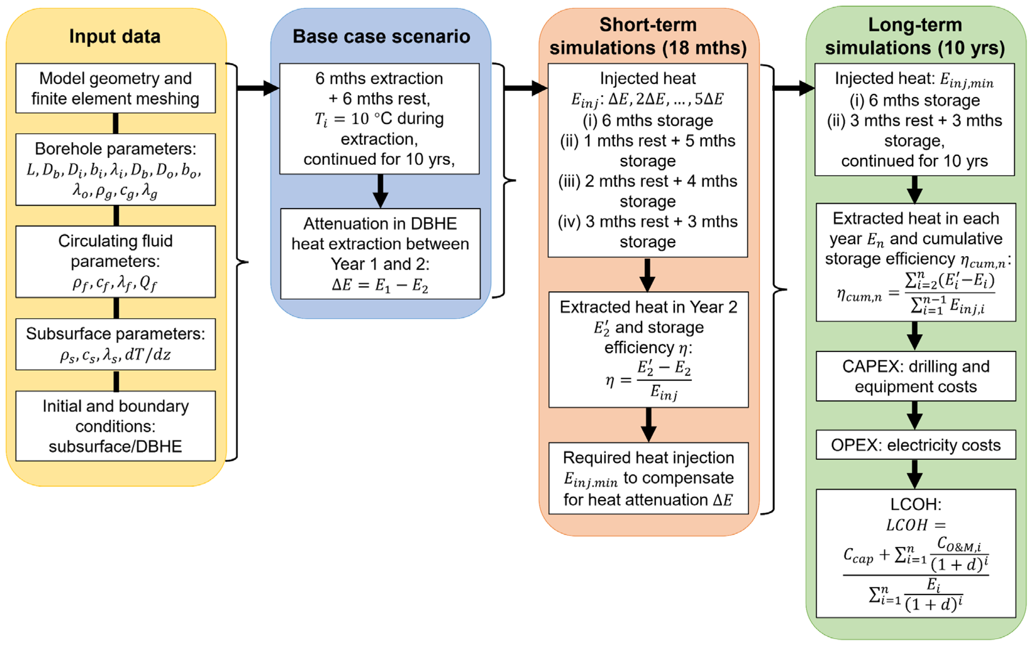
2. Materials and Methods
2.1. Governing Equations
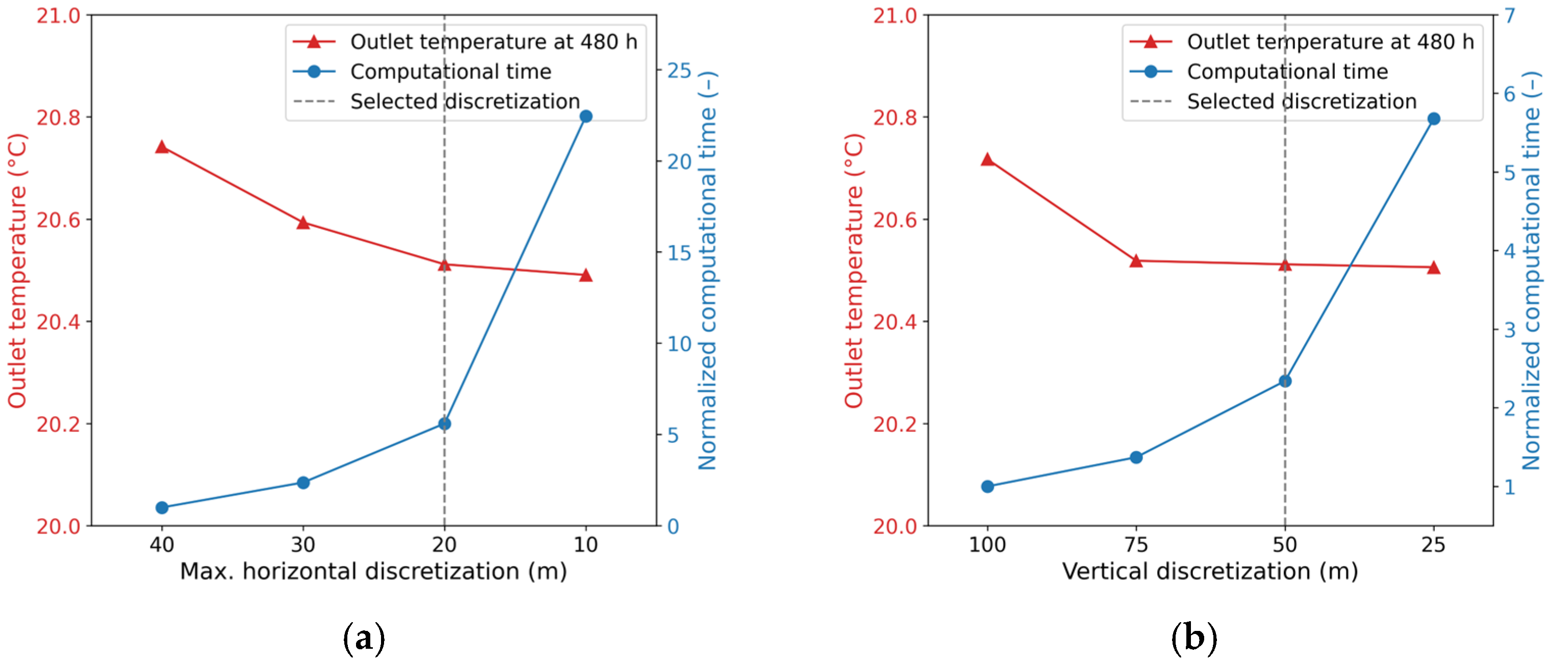
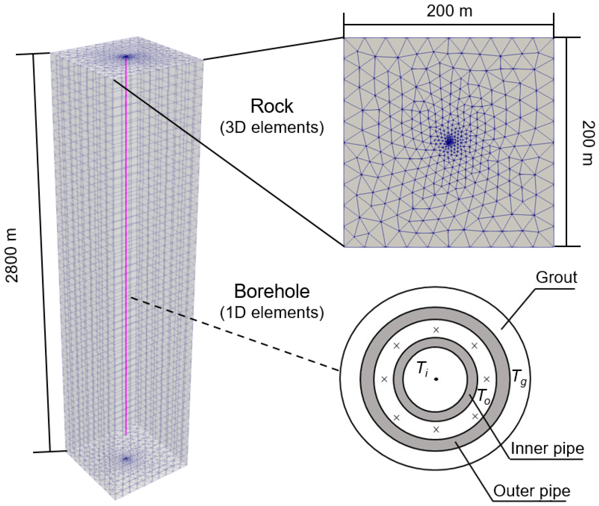
2.2. Numerical Model Setup
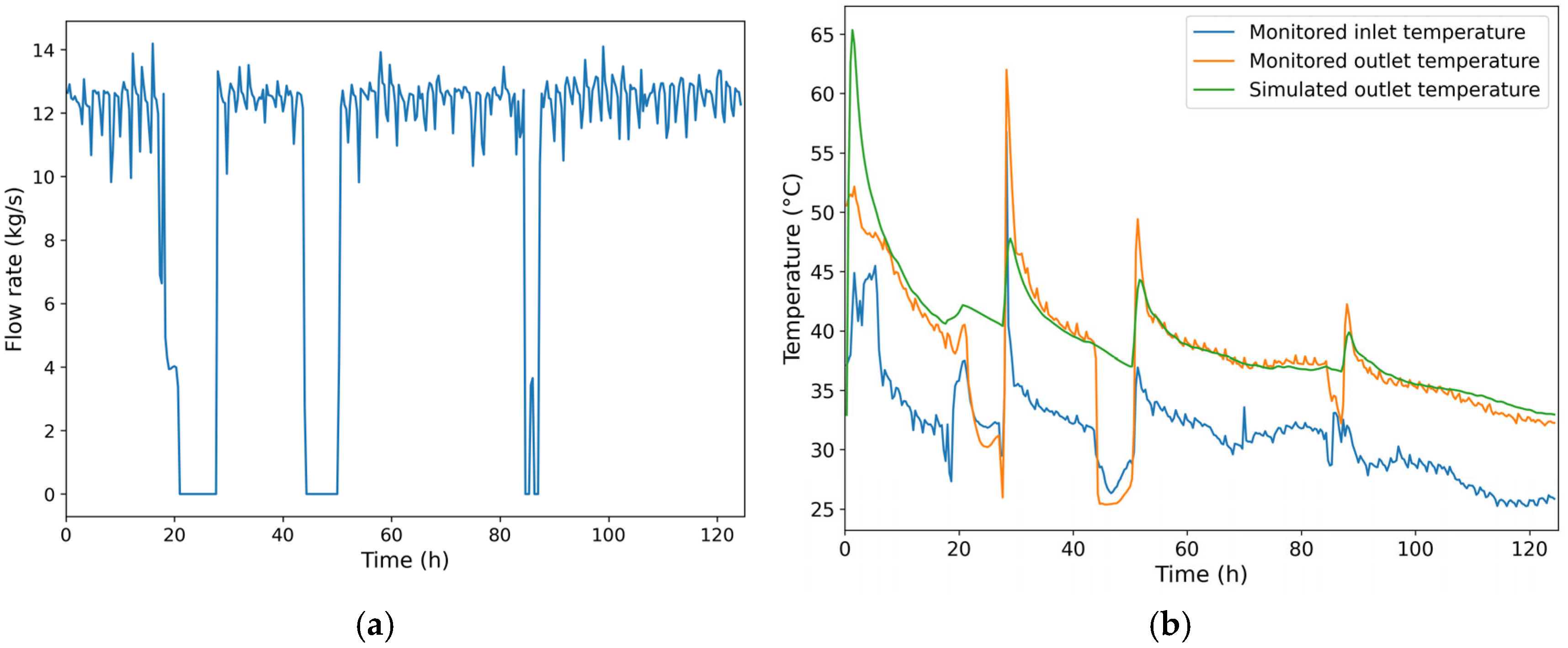
2.3. Model Validation
2.4. Simulated Scenarios
2.5. Evaluation Criteria
3. Results
3.1. Short-Term Analysis
3.1.1. Heat Extraction Only
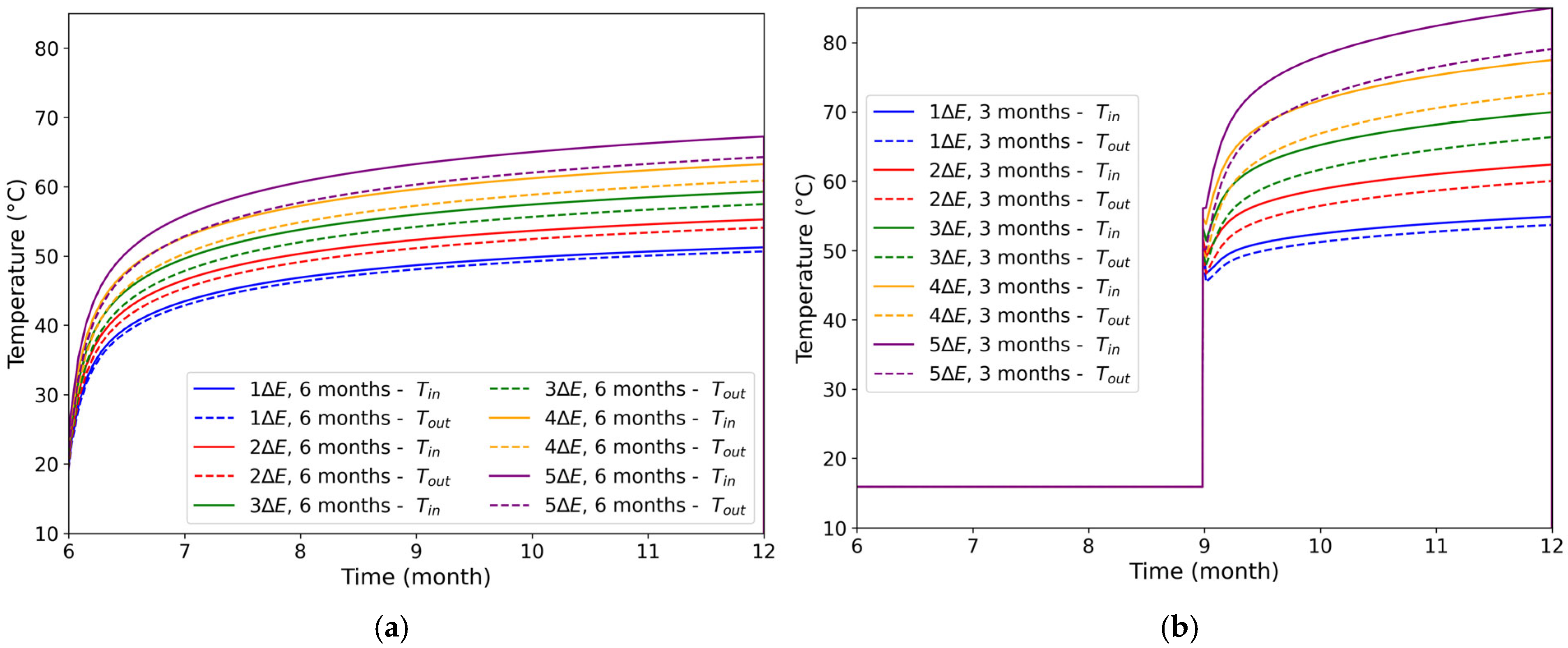
3.1.2. Heat Storage Phase
3.1.3. Heat Extraction Post-Storage
3.1.4. Heat Storage Efficiency
3.2. Long-Term Analysis
3.2.1. Heat Extraction Performance
3.2.2. Heat Storage Efficiency
3.2.3. Economic Performance
4. Discussion
4.1. Implications for Heat Storage via DBHE
4.2. Limitations and Outlook
5. Conclusions
- In the short-term analysis, the total extracted heat after seasonal heat storage increases linearly with the injected heat. The required heat injection to mitigate the thermal attenuation of the DBHE during the first two years increases with the length of the heat storage period.
- For the same heat storage duration, increasing the amount of injected heat leads to a decrease in heat storage efficiency. Conversely, for the same amount of injected heat, a shorter heat storage duration results in improved heat storage efficiency.
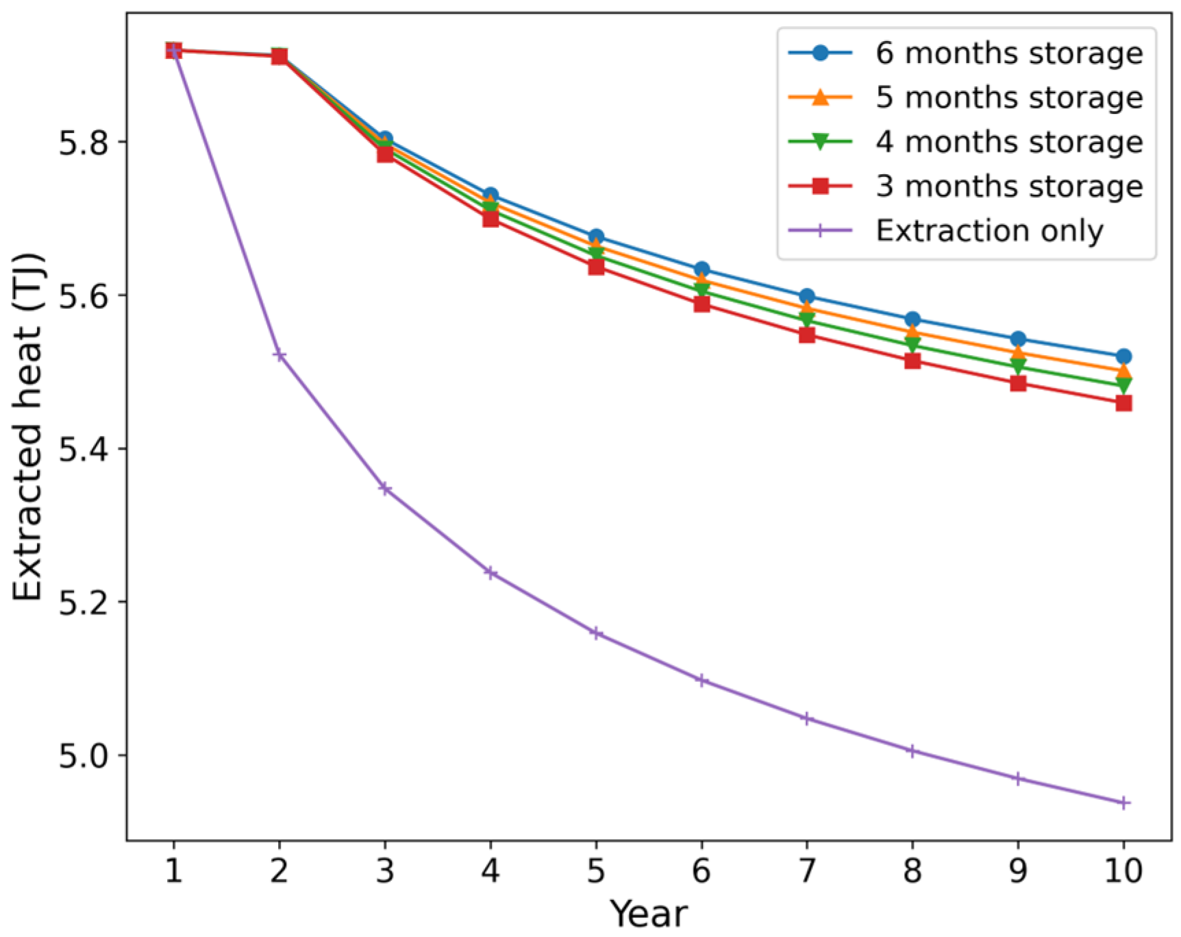
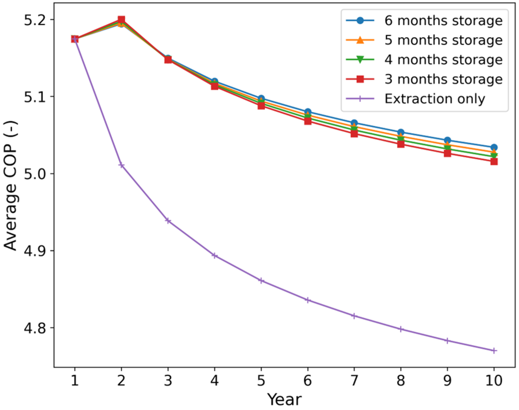
- When the required heat injection was applied annually, the extracted heat could only maintain its initial level in the second year, followed by a gradual decline. The improvement in annual heat extraction becomes more pronounced with longer heat storage periods, reaching a maximum increase of approximately 10% after 10 years in the 6-month storage scenario.
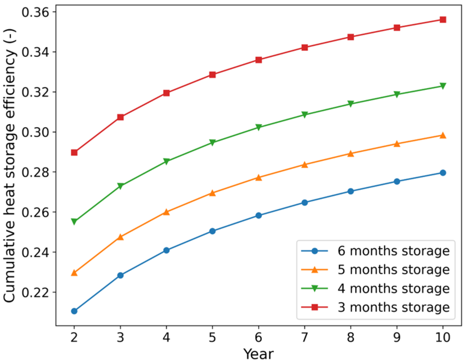
- The cumulative heat storage efficiency increases steadily with the number of charge/discharge cycles. The 10-year heat storage efficiencies reach at least 28%, exhibiting a 7% absolute increase from the second year onward, and surpassing previous estimates based on single-year storage scenarios.
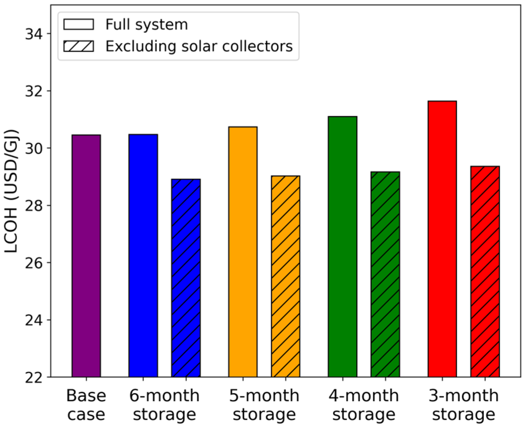
- For the case of the solar supplemental heat system, the of the heat storage scenarios is slightly higher than the base case without heat storage, with the of the 6-month storage scenario being almost equal to the base case. However, when solar collector costs are excluded, the of the heat storage scenarios becomes slightly lower than the base case, suggesting a modest improvement in economic performance. Therefore, it is advisable to implement seasonal heat storage strategies for DBHEs, especially when surplus heat is readily available at the surface.
- Future research should consider more diverse heat injection schemes, such as constant inlet temperature control, and explore multi-borehole configurations to better capture thermal interactions and optimize large-scale applications.
Author Contributions
Funding
Data Availability Statement
Conflicts of Interest
Nomenclature
| Nomenclature | |
| DBHE | Deep borehole heat exchanger |
| LCOH | Levelized cost of heat |
| UTES | Underground thermal energy storage |
| BTES | Borehole thermal energy storage |
| OpenGeoSys | OGS |
| BC | Boundary condition |
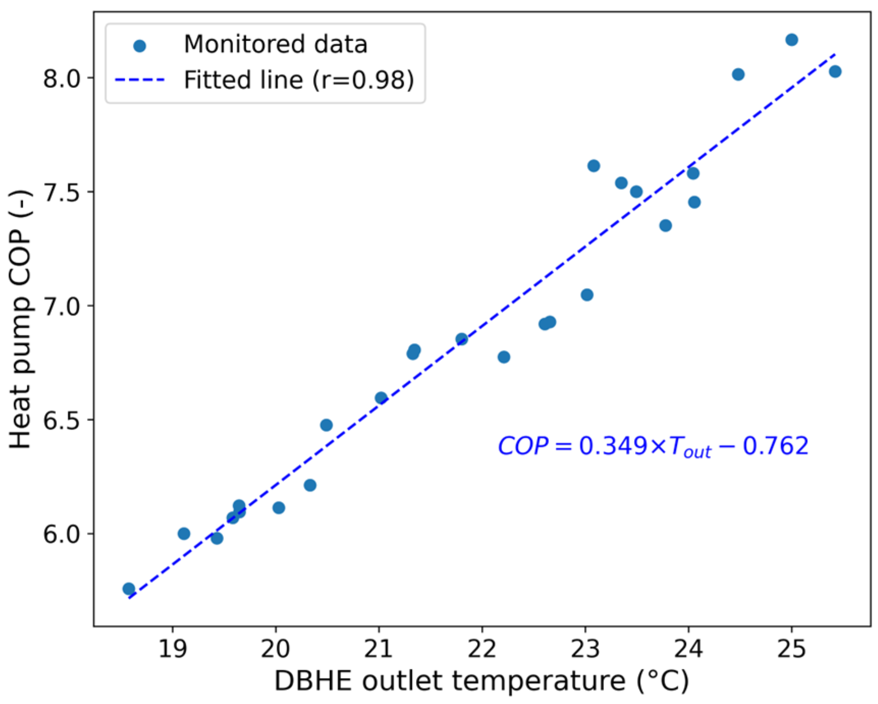
| COP | Coefficient of performance |
| Notations | |
| Density | |
| Specific heat capacity | |
| Flow velocity | |
| Hydrodynamic thermo-dispersion tensor | |
| Thermal conductivity | |
| Source/sink term | |
| Heat transfer coefficient | |
| Heat transfer boundary | |
| Temperature | |
| Effective porosity | |
| Volumetric flow rate | |
| Subscripts | |
| f | Circulating fluid |
| Inner pipe | |
| Outer pipe | |
| Grout | |
| Rock | |
| Groundwater | |
| Inlet | |
| Outlet |
Appendix A
Appendix A.1
Appendix A.2
References
- International Energy Agency. Heating. Available online: https://www.iea.org/energy-system/buildings/heating (accessed on 3 May 2025).
- Younger, P.L. Geothermal Energy: Delivering on the Global Potential. Energies 2015, 1, 11737–11754. [Google Scholar] [CrossRef]
- Huang, Y.; Kong, Y.; Cheng, Y.; Zhu, C.; Zhang, J.; Wang, J. Evaluating the Long-Term Sustainability of Geothermal Energy Utilization from Deep Coal Mines. Geothermics 2023, 107, 102584. [Google Scholar] [CrossRef]
- Kong, Y.; Pang, Z.; Shao, H.; Hu, S.; Kolditz, O. Recent Studies on Hydrothermal Systems in China: A Review. Geotherm. Energy 2014, 2, 19. [Google Scholar] [CrossRef]
- Soltani, M.; Moradi Kashkooli, F.; Souri, M.; Rafiei, B.; Jabarifar, M.; Gharali, K.; Nathwani, J.S. Environmental, Economic, and Social Impacts of Geothermal Energy Systems. Renew. Sustain. Energy Rev. 2021, 140, 110750. [Google Scholar] [CrossRef]
- van Oort, E.; Chen, D.; Ashok, P.; Fallah, A. Constructing Deep Closed-Loop Geothermal Wells for Globally Scalable Energy Production by Leveraging Oil and Gas ERD and HPHT Well Construction Expertise. In Proceedings of the SPE/IADC International Drilling Conference and Exhibition, Virtual, 8–12 March 2021. [Google Scholar] [CrossRef]
- Rybach, L.; Hopkirk, R. Shallow and Deep Borehole Heat Exchangers: Achievements and Prospects. In Proceedings of the World Geothermal Congress, Florence, Italy, 18–31 May 1995; Volume 1995, pp. 2133–2139. [Google Scholar]
- Cai, W.; Wang, F.; Chen, S.; Chen, C.; Liu, J.; Deng, J.; Kolditz, O.; Shao, H. Analysis of Heat Extraction Performance and Long-Term Sustainability for Multiple Deep Borehole Heat Exchanger Array: A Project-Based Study. Appl. Energy 2021, 289, 116590. [Google Scholar] [CrossRef]
- Brown, C.S.; Kolo, I.; Falcone, G.; Banks, D. Investigating Scalability of Deep Borehole Heat Exchangers: Numerical Modelling of Arrays with Varied Modes of Operation. Renew. Energy 2023, 202, 442–452. [Google Scholar] [CrossRef]
- Dijkshoorn, L.; Speer, S.; Pechnig, R. Measurements and Design Calculations for a Deep Coaxial Borehole Heat Exchanger in Aachen, Germany. Int. J. Geophys. 2013, 2013, 916541. [Google Scholar] [CrossRef]
- Le Lous, M.; Larroque, F.; Dupuy, A.; Moignard, A. Thermal Performance of a Deep Borehole Heat Exchanger: Insights from a Synthetic Coupled Heat and Flow Model. Geothermics 2015, 57, 157–172. [Google Scholar] [CrossRef]
- Holmberg, H.; Acuña, J.; Næss, E.; Sønju, O.K. Thermal Evaluation of Coaxial Deep Borehole Heat Exchangers. Renew. Energy 2016, 97, 65–76. [Google Scholar] [CrossRef]
- Cai, W.; Wang, F.; Jiang, J.; Wang, Z.; Liu, J.; Chen, C. Long-Term Performance Evaluation and Economic Analysis for Deep Borehole Heat Exchanger Heating System in Weihe Basin. Front. Earth Sci. 2022, 10, 806416. [Google Scholar] [CrossRef]
- Gascuel, V.; Raymond, J.; Rivard, C.; Marcil, J.-S.; Comeau, F.-A. Design and Optimization of Deep Coaxial Borehole Heat Exchangers for Cold Sedimentary Basins. Geothermics 2022, 105, 102504. [Google Scholar] [CrossRef]
- Luo, Y.; Xu, G.; Zhang, S.; Cheng, N.; Tian, Z.; Yu, J. Heat Extraction and Recover of Deep Borehole Heat Exchanger: Negotiating with Intermittent Operation Mode under Complex Geological Conditions. Energy 2022, 241, 122510. [Google Scholar] [CrossRef]
- Zhang, F.; Yu, M.; Sørensen, B.R.; Cui, P.; Zhang, W.; Fang, Z. Heat Extraction Capacity and Its Attenuation of Deep Borehole Heat Exchanger Array. Energy 2022, 254, 124430. [Google Scholar] [CrossRef]
- Meng, B.; Yang, Y.; Huang, Y.; Kolditz, O.; Shao, H. Remediation Potential of Borehole Thermal Energy Storage for Chlorinated Hydrocarbon Plumes: Numerical Modeling in a Variably-Saturated Aquifer. Front. Earth Sci. 2021, 9, 790315. [Google Scholar] [CrossRef]
- Tordrup, K.W.; Poulsen, S.E.; Bjørn, H. An Improved Method for Upscaling Borehole Thermal Energy Storage Using Inverse Finite Element Modelling. Renew. Energy 2017, 105, 13–21. [Google Scholar] [CrossRef]
- Welsch, B.; Rühaak, W.; Schulte, D.O.; Bär, K.; Sass, I. Characteristics of Medium Deep Borehole Thermal Energy Storage. Int. J. Energy Res. 2016, 40, 1855–1868. [Google Scholar] [CrossRef]
- Welsch, B. Technical, Environmental and Economic Assessment of Medium Deep Borehole Thermal Energy Storage Systems. Ph.D. Thesis, Universitäts-und Landesbibliothek Darmstadt, Darmstadt, Germany, 2019; p. 226. [Google Scholar]
- Huang, Y.; Pang, Z.; Kong, Y.; Watanabe, N. Assessment of the High-Temperature Aquifer Thermal Energy Storage (HT-ATES) Potential in Naturally Fractured Geothermal Reservoirs with a Stochastic Discrete Fracture Network Model. J. Hydrol. 2021, 603, 127188. [Google Scholar] [CrossRef]
- Fleuchaus, P.; Godschalk, B.; Stober, I.; Blum, P. Worldwide Application of Aquifer Thermal Energy Storage—A Review. Renew. Sustain. Energy Rev. 2018, 94, 861–876. [Google Scholar] [CrossRef]
- Qin, X.; Zhao, Y.; Dai, C.; Wei, J.; Xue, D. Thermal Performance Analysis on the Seasonal Heat Storage by Deep Borehole Heat Exchanger with the Extended Finite Line Source Model. Energies 2022, 15, 8366. [Google Scholar] [CrossRef]
- Hirvijoki, E.; Hirvonen, J. The Potential of Intermediate-to-Deep Geothermal Boreholes for Seasonal Storage of District Heat. Renew. Energy 2022, 198, 825–832. [Google Scholar] [CrossRef]
- Brown, C.S.; Kolo, I.; Falcone, G.; Banks, D. Repurposing a Deep Geothermal Exploration Well for Borehole Thermal Energy Storage: Implications from Statistical Modelling and Sensitivity Analysis. Appl. Therm. Eng. 2023, 220, 119701. [Google Scholar] [CrossRef]
- Brown, C.S.; Doran, H.; Kolo, I.; Banks, D.; Falcone, G. Investigating the Influence of Groundwater Flow and Charge Cycle Duration on Deep Borehole Heat Exchangers for Heat Extraction and Borehole Thermal Energy Storage. Energies 2023, 16, 2677. [Google Scholar] [CrossRef]
- Zhang, Y.; Ye, C.; Kong, Y.; Gong, Y.; Zhang, D.; Yao, Y. Thermal Attenuation and Heat Supplementary Analysis of Medium-Deep Coaxial Borehole System-Based on a Practical Project. Energy 2023, 270, 126805. [Google Scholar] [CrossRef]
- Huang, S.; Li, J.; Zhu, K.; Dong, J.; Li, J.; Jiang, Y. Energy Conversion through Deep Borehole Heat Exchanger Systems: Heat Storage Analysis and Assessment of Threshold Inlet Temperature. Energy Convers. Manag. 2023, 294, 117589. [Google Scholar] [CrossRef]
- Fu, H.; Yu, M.; Liu, J.; Cui, P.; Zhang, W.; Mao, Y.; Zhuang, Z. Influence of Heat Storage on Performance of Multi-Borehole Mid-Deep Borehole Heat Exchangers. J. Energy Storage 2024, 90, 111718. [Google Scholar] [CrossRef]
- Kolditz, O.; Bauer, S.; Bilke, L.; Böttcher, N.; Delfs, J.-O.; Fischer, T.; Görke, U.J.; Kalbacher, T.; Kosakowski, G.; McDermott, C.I.; et al. OpenGeoSys: An Open-Source Initiative for Numerical Simulation of Thermo-Hydro-Mechanical/Chemical (THM/C) Processes in Porous Media. Environ. Earth Sci. 2012, 67, 589–599. [Google Scholar] [CrossRef]
- Diersch, H.J.G.; Bauer, D.; Heidemann, W.; Rühaak, W.; Schätzl, P. Finite Element Modeling of Borehole Heat Exchanger Systems. Part 1. Fundamentals. Comput. Geosci. 2011, 37, 1122–1135. [Google Scholar] [CrossRef]
- Al-Khoury, R.; Kölbel, T.; Schramedei, R. Efficient Numerical Modeling of Borehole Heat Exchangers. Comput. Geosci. 2010, 36, 1301–1315. [Google Scholar] [CrossRef]
- Brown, C.S.; Kolo, I.; Banks, D.; Falcone, G. Comparison of the Thermal and Hydraulic Performance of Single U-Tube, Double U-Tube and Coaxial Medium-to-Deep Borehole Heat Exchangers. Geothermics 2024, 117, 102888. [Google Scholar] [CrossRef]
- Diersch, H.-J.; Bauer, D.; Heidemann, W.; Rühaak, W.; Schätzl, P. Finite Element Modeling of Borehole Heat Exchanger Systems: Part 2. Numerical Simulation. Comput. Geosci. 2011, 37, 1136–1147. [Google Scholar] [CrossRef]
- Zhang, Q.; Xiao, H.; Rao, S.; Shi, Y.; Li, W.; Hu, G. Characteristics and Controlling Factors of the Present Geothermal Field in the Songliao Basin. Bull. Geol. Sci. Technol. 2023, 42, 191–204. [Google Scholar]
- Li, X.; Zhu, C.Q.; Qiu, N.S.; Tang, B.N.; Fu, X.L. Thermal Conductivity of Rocks and Its Influencing Factors in Northern Songliao Basin. Acta Geosci. Sin. 2023, 44, 70–78. [Google Scholar] [CrossRef]
- Chen, C.; Shao, H.; Naumov, D.; Kong, Y.; Tu, K.; Kolditz, O. Numerical Investigation on the Performance, Sustainability, and Efficiency of the Deep Borehole Heat Exchanger System for Building Heating. Geotherm. Energy 2019, 7, 18. [Google Scholar] [CrossRef]
- Huang, Y.; Zhang, Y.; Xie, Y.; Zhang, Y.; Gao, X. Thermal Performance Analysis on the Composition Attributes of Deep Coaxial Borehole Heat Exchanger for Building Heating. Energy Build. 2020, 221, 110019. [Google Scholar] [CrossRef]
- Rad, F.M.; Fung, A.S. Solar Community Heating and Cooling System with Borehole Thermal Energy Storage--Review of Systems. Renew. Sustain. Energy Rev. 2016, 60, 1550–1561. [Google Scholar] [CrossRef]
- Deng, J.; He, S.; Wei, Q.; Li, J.; Liu, H.; Zhang, Z.; Zhang, H. Field Test and Optimization of Heat Pumps and Water Distribution Systems in Medium-Depth Geothermal Heat Pump Systems. Energy Build. 2020, 209, 109724. [Google Scholar] [CrossRef]
- Wang, G.; Song, X.; Shi, Y.; Yulong, F.; Yang, R.; Li, J. Comparison of Production Characteristics of Various Coaxial Closed-Loop Geothermal Systems. Energy Convers. Manag. 2020, 225, 113437. [Google Scholar] [CrossRef]
- Hein, P.; Kolditz, O.; Görke, U.J.; Bucher, A.; Shao, H. A Numerical Study on the Sustainability and Efficiency of Borehole Heat Exchanger Coupled Ground Source Heat Pump Systems. Appl. Therm. Eng. 2016, 100, 421–433. [Google Scholar] [CrossRef]
- Skarphagen, H.; Banks, D.; Frengstad, B.S.; Gether, H. Design Considerations for Borehole Thermal Energy Storage (BTES): A Review with Emphasis on Convective Heat Transfer. Geofluids 2019, 2019, 4961781. [Google Scholar] [CrossRef]
- Seib, L.; Welsch, B.; Bossennec, C.; Frey, M.; Sass, I. Finite Element Simulation of Permeable Fault Influence on a Medium Deep Borehole Thermal Energy Storage System. Geotherm. Energy 2022, 10, 15. [Google Scholar] [CrossRef]
- Beckers, K.F.; McCabe, K. GEOPHIRES v2. 0: Updated Geothermal Techno-Economic Simulation Tool. Geotherm. Energy 2019, 7, 5. [Google Scholar] [CrossRef]
- Sun, W.; Zhang, W.; Zhao, Z.; Huang, Y.; Ren, Y.; Ren, L.; Yan, Y.; Ji, S.; Wang, S.; Kong, Y. Qualitative Assessment of Optimizing the Well Spacings Based on the Economic Analysis. Geotherm. Energy 2024, 12, 16. [Google Scholar] [CrossRef]
- Wang, G.; Ma, H.; Liu, S.; Yang, D.; Xu, X. Thermal Power Extraction from a Deep, Closed-Loop, Multi-Level, Multi-Branch, U-Shaped Borehole Heat Exchanger Geothermal System. Renew. Energy 2022, 198, 894–906. [Google Scholar] [CrossRef]
- Survey, C.G. Geological Survey Project Budget Standards (2021); China Geological Survey: Beijing, China, 2021. [Google Scholar]
- Lee, M.; Ham, S.H.; Lee, S.; Kim, J.; Kim, Y. Multi-Objective Optimization of Solar-Assisted Ground-Source Heat Pumps for Minimizing Life-Cycle Cost and Climate Performance in Heating-Dominated Regions. Energy 2023, 270, 126868. [Google Scholar] [CrossRef]
- Bhowmik, H.; Amin, R. Efficiency Improvement of Flat Plate Solar Collector Using Reflector. Energy Rep. 2017, 3, 119–123. [Google Scholar] [CrossRef]
- National Renewable Energy Laboratory (NREL). NSRDB International Data Sets. Available online: https://nsrdb.nrel.gov (accessed on 3 May 2025).
- Dengjia, W.; Ting, Q.; Yaowen, C.; Yanfeng, L.; Ruichao, Z. Study on Coupled Heating Performance of Absorption Heat Pump Driving Solar Collector System. Acta Energiae Solaris Sin. 2021, 42, 129–136. [Google Scholar] [CrossRef]
- Jilin Provincial Development and Reform Commission. Notice on Relevant Policies and Guidelines. Available online: https://jldrc.jl.gov.cn/zycpjg/dj/202110/t20211028_8262190.html (accessed on 3 May 2025). (In Chinese)
- Yousaf, S.; Bradshaw, C.R.; Kamalapurkar, R.; San, O. A Gray-Box Model for Unitary Air Conditioners Developed with Symbolic Regression. Int. J. Refrig. 2024, 168, 696–707. [Google Scholar] [CrossRef]


| Compartment | Parameter | Value | Unit |
|---|---|---|---|
| Borehole | 2600 | m | |
| 0.311 | m | ||
| 0.1397 | m | ||
| 0.01905 | m | ||
| 0.42 | W/(m·K) | ||
| 0.2445 | m | ||
| 0.01003 | m | ||
| 40 | W/(m·K) | ||
| 2190 | kg/m3 | ||
| 1735.16 | J/(kg·K) | ||
| 2 | W/(m·K) | ||
| Circulating fluid | 998 | kg/m3 | |
| 4190 | J/(kg·K) | ||
| 0.6 | W/(m·K) | ||
| 0.013 | m3/s | ||
| Subsurface | 1760 | kg/m3 | |
| 1433 | J/(kg·K) | ||
| W/(m·K) | |||
| 0–1650 m depth | 1.5 [35,36] | ||
| 1650–2800 m depth | 2.7 [35,36] | ||
| 31.5 | °C/km |
| Scenario | , 6 mths | , 6 mths | , 6 mths | , 6 mths | , 6 mths |
| Extracted heat after storage (TJ) | 5.66 | 5.76 | 5.86 | 5.97 | 6.07 |
| Heat storage efficiency (%) | 48.1 | 33.9 | 29.2 | 26.9 | 25.4 |
| Scenario | , 5 mths | , 5 mths | , 5 mths | , 5 mths | , 5 mths |
| Extracted heat after storage (TJ) | 5.67 | 5.78 | 5.89 | 6.00 | 6.11 |
| Heat storage efficiency (%) | 49.8 | 35.8 | 31.1 | 28.7 | 27.3 |
| Scenario | , 4 mths | , 4 mths | , 4 mths | , 4 mths | , 4 mths |
| Extracted heat after storage (TJ) | 5.68 | 5.81 | 5.93 | 6.05 | 6.18 |
| Heat storage efficiency (%) | 52.0 | 38.1 | 33.4 | 31.1 | 29.7 |
| Scenario | , 3 mths | , 3 mths | , 3 mths | , 3 mths | , 3 mths |
| Extracted heat after storage (TJ) | 5.70 | 5.84 | 5.98 | 6.12 | 6.27 |
| Heat storage efficiency (%) | 54.9 | 41.3 | 36.8 | 34.5 | 33.2 |
| Scenario | Heat Injection (GJ) | Solar Collector Area (m2) | Capital Expense (103 USD) | |||
|---|---|---|---|---|---|---|
| Solar Supplemental System | Drilling and Pipe | Surface Equipment | Total | |||
| Base case | 0 | 0 | 0 | 942.7 | 71.9 | 1014.6 |
| 6-month storage | 1853 | 882 | 104.2 | 942.7 | 71.9 | 1118.7 |
| 5-month storage | 1694 | 968 | 114.3 | 942.7 | 71.9 | 1128.9 |
| 4-month storage | 1526 | 1090 | 128.7 | 942.7 | 71.9 | 1143.3 |
| 3-month storage | 1342 | 1279 | 151.0 | 942.7 | 71.9 | 1165.5 |
Disclaimer/Publisher’s Note: The statements, opinions and data contained in all publications are solely those of the individual author(s) and contributor(s) and not of MDPI and/or the editor(s). MDPI and/or the editor(s) disclaim responsibility for any injury to people or property resulting from any ideas, methods, instructions or products referred to in the content. |
© 2025 by the authors. Licensee MDPI, Basel, Switzerland. This article is an open access article distributed under the terms and conditions of the Creative Commons Attribution (CC BY) license (https://creativecommons.org/licenses/by/4.0/).
Share and Cite
Meng, B.; Zhou, Y.; Chen, W.; Luo, W.; Ding, R.; Cai, W.; Chen, C. Investigating the Impact of Seasonal Heat Storage on the Thermal and Economic Performance of a Deep Borehole Heat Exchanger: A Numerical Simulation Study. Buildings 2025, 15, 1575. https://doi.org/10.3390/buildings15091575
Meng B, Zhou Y, Chen W, Luo W, Ding R, Cai W, Chen C. Investigating the Impact of Seasonal Heat Storage on the Thermal and Economic Performance of a Deep Borehole Heat Exchanger: A Numerical Simulation Study. Buildings. 2025; 15(9):1575. https://doi.org/10.3390/buildings15091575
Chicago/Turabian StyleMeng, Boyan, Yang Zhou, Wenwen Chen, Wenxing Luo, Rui Ding, Wanlong Cai, and Chaofan Chen. 2025. "Investigating the Impact of Seasonal Heat Storage on the Thermal and Economic Performance of a Deep Borehole Heat Exchanger: A Numerical Simulation Study" Buildings 15, no. 9: 1575. https://doi.org/10.3390/buildings15091575
APA StyleMeng, B., Zhou, Y., Chen, W., Luo, W., Ding, R., Cai, W., & Chen, C. (2025). Investigating the Impact of Seasonal Heat Storage on the Thermal and Economic Performance of a Deep Borehole Heat Exchanger: A Numerical Simulation Study. Buildings, 15(9), 1575. https://doi.org/10.3390/buildings15091575