Article

Experimental Study of the Axial Tensile Properties of Basalt Fiber Textile–Reinforced Fine-Aggregate Concrete Thin Slab

The Key Laboratory of Urban Security and Disaster Engineering, Ministry of Education, Beijing University of Technology, Beijing 100124, China
*
Author to whom correspondence should be addressed.
Buildings 2025, 15(9), 1540; https://doi.org/10.3390/buildings15091540
Submission received: 7 March 2025 / Revised: 25 April 2025 / Accepted: 28 April 2025 / Published: 2 May 2025
(This article belongs to the Section Building Materials, and Repair & Renovation)

Abstract

Traditional concrete has low tensile strength, is prone to cracking, and has poor durability, which limits its scope of application. Basalt Fiber Textile–Reinforced Concrete (BTRC), a new type of fiber-reinforced cement material, offers advantages such as light weight, increased strength, improved crack resistance, and high durability. It effectively addresses the limitations of traditional concrete. However, the tensile properties of BTRC have not been fully studied, especially with fine aggregate concrete as the matrix, and there are few reports on this topic. Therefore, this study conducted uniaxial tensile tests of Basalt Textile–Reinforced Fine Aggregate Concrete (BTRFAC) and systematically investigated the effects of two mesh sizes (5 mm × 5 mm and 10 mm × 10 mm) and two to four layers of fiber mesh on the tensile strength, strain hardening behavior, crack propagation, and ductile tensile mechanical properties of BTRFAC thin slabs. The tests revealed that an increase in the number of fiber mesh layers significantly reinforced the material’s tensile strength and ductility. The tensile strength of the 5 mm mesh specimen (four-layer mesh) reached 2.96 MPa, which is 193% higher than plain concrete, and the ultimate tensile strain increased by 413%. The tensile strength of the 10 mm mesh specimen (four-layer mesh) was 2.12 MPa, which is 109% higher than plain concrete, and the ultimate tensile strain increased by 298%. The strength utilization rate of the 5 mm and 10 mm mesh fibers was 41% and 54% respectively, mainly due to the weakening effect caused by interface slippage between the fiber mesh and the matrix. An excessively small mesh size may lead to premature debonding from the matrix, but its denser fiber distribution and larger bonding area exhibit better strain hardening characteristics. More than three layers of fiber mesh can significantly improve the uniformity of crack distribution and delay propagation of the main crack. A calculation formula for the tensile bearing capacity of BTRFAC thin slabs is proposed, and the error between the theoretical value and the experimental value was very small. This research provides a theoretical basis and reference data for the design and application of basalt fiber mesh–reinforced concrete thin slabs.

1. Introduction

Textile-Reinforced Concrete (TRC) is a new type of fiber-reinforced cement-based composite material, which uses multi-axial textile fabrics as reinforcement and high-performance fine concrete as the matrix [1,2,3,4,5,6,7,8,9,10]. Due to its high load-bearing capacity, high ductility, and corrosion resistance, TRC has been widely used in the field of engineering reinforcement [11,12,13,14,15]. Moreover, its excellent durability, good deformation performance, and good deformation compatibility with reinforced concrete substrates have brought new vitality and innovation to materials and technology in the field of engineering reinforcement, and have also laid a solid foundation for the broad prospects of TRC [16,17,18,19].
The fiber meshes used in TRC mainly include basalt fiber mesh, carbon fiber mesh, and alkali-resistant glass fiber mesh [20,21,22,23,24]. These are two-dimensional continuous fiber reinforcement materials with high tensile strength in both the warp and weft directions. Axial tensile mechanical property tests, as the core method used for evaluating and determining the mechanical characteristics of TRC, play a crucial role in deeply understanding a material’s tensile strength, ductility, fracture toughness, and other key mechanical behaviors in practical applications. Not only can these tests provide a scientific basis for material design, preparation, and application, but they also offer indispensable data support for the reliability and durability analysis of related engineering structures [25,26,27,28]. In this regard, some scholars have conducted relevant studies. Dong [29] performed TRC axial tensile tests of different glass fiber mesh–reinforced matrices at various reinforcement rates. The test results revealed that the combination of glass fiber mesh and PVA fibers could effectively improve the crack pattern, greatly enhancing the tensile strength and strain of the specimens, demonstrating excellent and stable deformation capacity. Suh [30] performed uniaxial tensile tests of TRC with carbon fiber mesh–reinforced mortar matrices of different mesh widths. The specimens containing carbon fiber mesh exhibited increased cracking strength and ultimate strength compared to specimens without mesh.
Furthermore, the slip performance between the mesh and matrix in TRC is a key research focus to ensure the mesh can be fully utilized [31,32]. Yin [33] studied the interfacial bonding performance between TRC and masonry, considering basalt and glass fiber mesh, different matrices, and interface bond lengths. The study found that the glass fiber mesh had better integrity, and longer bond lengths resulted in greater ultimate load and bond strength. Narman [34] investigated the slip performance of carbon fiber–reinforced polymers and ultra-high performance concrete matrix incorporating styrene-butadiene rubber fibers and found that the fibers are beneficial in mitigating up to 20% of the detrimental effects of smooth carbon fiber–reinforced polymer geometry.
Among various TRC reinforcement materials, basalt fiber mesh stands out for its high strength-to-weight ratio and environmental durability, increasingly gaining attention for reinforcement of the mechanical properties of cement-based matrices [35,36,37,38,39]. He [40] conducted tests on the tensile properties of Basalt Fiber Mesh–Reinforced Mortar (BTRM) before and after exposure to high temperatures of 300 °C, and the results showed that, at room temperature, BTRM could effectively increase the peak stress by about 30%. However, with the increase of exposure time to high temperatures, the cracking and peak stress of BTRM significantly decreased. Meriggi [41] used Basalt Fiber Mesh–Reinforced Lime Mortar (BTRLM) for strengthening masonry walls and measured its mechanical properties under static cyclic shear compression tests. The reinforced specimens exhibited increased shear strength by 27%, improved failure mode, and reduced crack width. Prasath [42] strengthened RC columns with Basalt Fiber Mesh–Reinforced Cement Matrix (BFRCM) and determined their mechanical properties under cyclic loading. BFRCM conferred better structural strength, increased load-bearing capacity, and greater deflection, effectively enhancing seismic performance.
Although these studies have laid the foundation for understanding the mechanical properties of basalt fiber mesh–reinforced mortar, existing research has primarily focused on the tensile properties of individual fibers or the matrix, as well as related investigations on reinforced specimens. Notably, studies on the synergistic effects of basalt fiber mesh size and mesh ratio on crack propagation, strain hardening behavior, and fiber–matrix interfacial properties remain extremely limited. Furthermore, research employing fine-aggregate concrete as the matrix has rarely been reported, which holds significant academic value and warrants further exploration.
To address the aforementioned deficiencies, this study systematically evaluated the mesh size (5 mm × 5 mm and 10 mm × 10 mm) and the number of mesh layers (two to four layers) on tensile strength, crack distribution, and ductility through axial tensile tests on Basalt Textile–Reinforced Fine Aggregate Concrete (BTRFAC) thin slabs (thin slab dimensions (length × width × height): 400 mm × 50 mm × 20 mm). Fine-aggregate concrete matrix was used to ensure effective penetration of the fiber mesh, and quantitative analysis was conducted of fiber strength utilization and strain-hardening mechanisms. The dual role of mesh density and layering in optimizing crack patterns and delaying failure was elucidated, revealing the relationship between mesh density and fiber efficiency due to interfacial debonding. In addition, we conducted innovative research on theoretical calculation of the tensile load-bearing capacity of BTRFAC.

2. Test Material

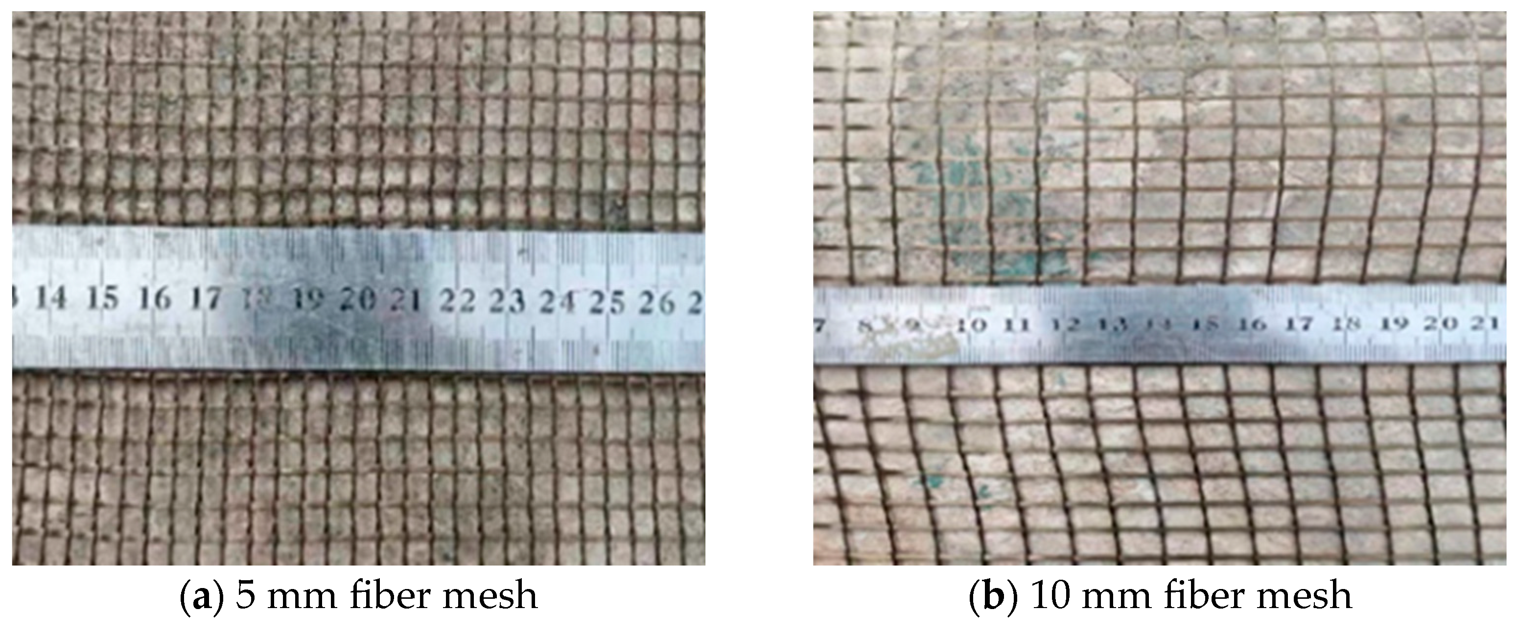
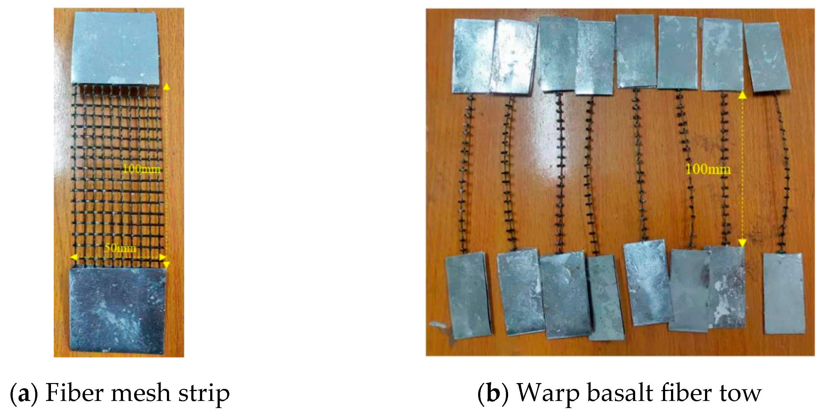
2.1. Basalt Fiber Mesh
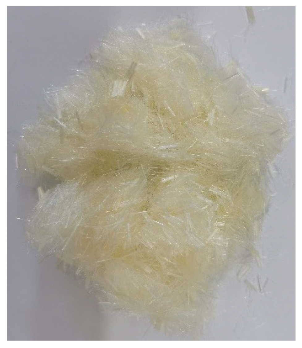
The basalt fiber mesh used in this experiment is produced by Zhejiang Shijin Basalt Fiber Co., Ltd., Zhejiang, China. There are two types of mesh sizes, which are 5 mm × 5 mm and 10 mm × 10 mm, respectively. Both sizes of fiber mesh are woven in a bidirectional manner, with the warp fibers twisted together to fix the weft single-fiber bundle, as shown in Figure 1. Since a single-fiber bundle contains thousands of fine fiber filaments, when embedded in the concrete matrix, the fine concrete cannot fully penetrate the interior of the fiber filaments to form an effective bond, and only the outer fiber filaments can bond well with the concrete matrix. The force is transmitted to the internal fiber filaments through friction between the inner and outer fiber filaments. However, due to the smooth surface of the fiber filaments, the transmission efficiency between the inner and outer fiber filaments is relatively low. Therefore, the fiber mesh surface is treated with styrene-acrylic emulsion to enhance effective bonding between the inner and outer fiber filaments, making it an integral part that can withstand forces collaboratively, thus fully utilizing the high tensile strength of the fiber mesh. Since all the designed slab specimens in this experiment are one-way slabs, mainly loaded by the warp fiber bundles, only the mechanical properties of the warp fiber bundles are tested. The cross-sectional area of a single fiber bundle is calculated according to Equation (1) [43].
A t = T e x ρ v ,
where A t represents the theoretical cross-sectional area of a single fiber bundle, in mm2. T e x is the linear density of the fiber, in g/km. ρ v is the volume density of the fiber, in g/cm3.
However, during the stretching process, twisting of the warp fiber bundles might lead to stripping of the weft fiber bundles, which in turn causes fluctuations in the load. Therefore, there might be significant deviation between the tensile properties of the fiber mesh obtained from single-fiber testing and the actual values. Hence, in this study, a fiber mesh strip with a width of 50 mm (10 fiber bundles) and a test gauge length of 100 mm was prepared for mechanical property testing of the fiber mesh.
Referring to the GB/T 3362-2005 [44], in order to prevent the fiber bundle from breaking due to stress concentration at the ends caused by the clamping of the fixture during the loading process, special 0.3 mm aluminum slabs with corrugated indentations were used to reinforce both ends of the specimen, thereby enhancing the anchoring effect at the ends. Eight basalt fiber bundles and eight basalt fiber mesh strips were tested (Figure 2). Before testing, the samples were allowed to stand for 24 h at room temperature to give the colloid sufficient time to air-dry and cure.
The mechanical properties of basalt fiber mesh were tested on an MTS electro-hydraulic servo testing machine in the United States, with a measuring range of 300 kN. During the test, the specimen was clamped at both ends of the testing machine using a fixture, as shown in Figure 3. The fixture was wedge-shaped, capable of tightly adhering to the aluminum slabs at both ends of the specimen without causing slippage. The displacement loading method was adopted for the specimen process, with a loading speed of 0.5 mm/min. The load and the deformation of the specimen were simultaneously collected by the built-in load sensor and displacement sensor in the testing machine.
The failure modes of the basalt fiber bundle and fiber mesh strip specimens are shown in Figure 4. As can be seen, due to the uneven force during the loading process, the fracture of each fiber bundle does not occur simultaneously. The mechanical property indices of the fiber mesh strips are calculated according to reference [44], where the tensile strength of the fiber mesh is calculated according to Equation (2):
σ t u = n × P × ρ v T e x × 10 6
where σ t u represents the tensile strength of the fiber mesh strip, measured in MPa. P is the measured failure load from the test, in N. n is the number of fiber bundles within the width of the fiber mesh strip, and for this test, the value is n = 10 .
The tensile elastic modulus is calculated according to Equation (3), and the breaking elongation rate is calculated according to Equation (4).
E t = P × ρ v T e x   ×   L L   ×   10 9
ε t = L b L × 100 %
where E t is the tensile elastic modulus of the fiber mesh strip. P is the load difference intercepted on the initial linear segment of the tensile stress–strain curve from the test, in N. L is the gauge length of the specimen, in mm, and for this test, the value is 100 mm. L is the elongation of the specimen’s gauge length relative to P , in mm. ε t is the elongation rate at the failure of the specimen, in %.
The tensile load-displacement curve of the basalt fiber mesh strip obtained from the tensile test is shown in Figure 5. As can be seen, the load–displacement relationship of the fiber mesh strip almost exhibits a linear elastic relationship, with only slight fluctuations appearing when the specimen is about to fail. This is because the fiber bundles do not break simultaneously.
The basic mechanical properties of the basalt fiber mesh strips, calculated by substituting the experimentally measured parameters into the above-mentioned calculation formula, are summarized in Table 1.

2.2. PVA Fiber

PVA fiber is a new type of green building material with excellent comprehensive properties [45,46]. It has high tensile strength and elastic modulus, good corrosion resistance, and anti-aging performance. Additionally, it possesses good chemical stability, being non-toxic and harmless. Its hydrophilicity allows for better adhesion to the composite material matrix, which imparts good toughness and deformation capacity to the matrix, thereby enhancing the integrity of the composite materials. The PVA fiber used in this experiment is produced by Fujian Yong an Baohualin Industrial Development Co., Ltd., Yongan, China. and its basic performance indicators are shown in Table 2. The PVA fibers are shown in Figure 6. To improve workability between the matrix and the fiber mesh, this study adopted a low fiber dosage scheme. All specimens were mixed with PVA fibers at a volume fraction of 0.1%.

2.3. Fine-Aggregate Concrete

The concrete matrix used in this test is fine-aggregate concrete (i.e., the maximum particle size of the aggregate does not exceed 2 mm), which has good workability (fluidity and ease of placement). It can self-compact during the pouring process, not only allowing the matrix to pass through the mesh of the fiber mesh smoothly and form an effective bond with it, reducing the pores, but also ensuring that the concrete matrix between the multi-layer fiber mesh remains dense. The mix proportion of the matrix concrete is shown in Table 3. The acrylic emulsion TF627 was used for modification of the cement-based materials. After the acrylic emulsion is added to the cement mortar, it forms a dense mesh structure with the cement hydration products, which can significantly improve the bond strength between the cement mortar and the substrate [47], as well as enhancing the flexural and tensile strength of the cement mortar. The modified cement mortar has better durability and water resistance [48].
The basic mechanical properties of fine concrete were tested according to the method specified in JGJ/T70-2009 [49]. The specimens were cubes with a side length of 70.7 mm, and their cube compressive strength and flexural strength were measured on a universal testing machine with a capacity of 300 kN, as shown in Figure 7. The loading process was controlled by load, with a loading rate of 2 kN/s. The compressive strength of the specimen was obtained by dividing the maximum load measured during the test by the cross-sectional area of the specimen. The ultimate compressive strengths of the fine concrete matrix at 7 d and 28 d were measured to be 37.2 MPa and 53.5 MPa, respectively, and the flexural strengths at 7 d and 28 d were 6.4 MPa and 12.6 MPa, respectively.

3. Design and Preparation of Thin Slabs

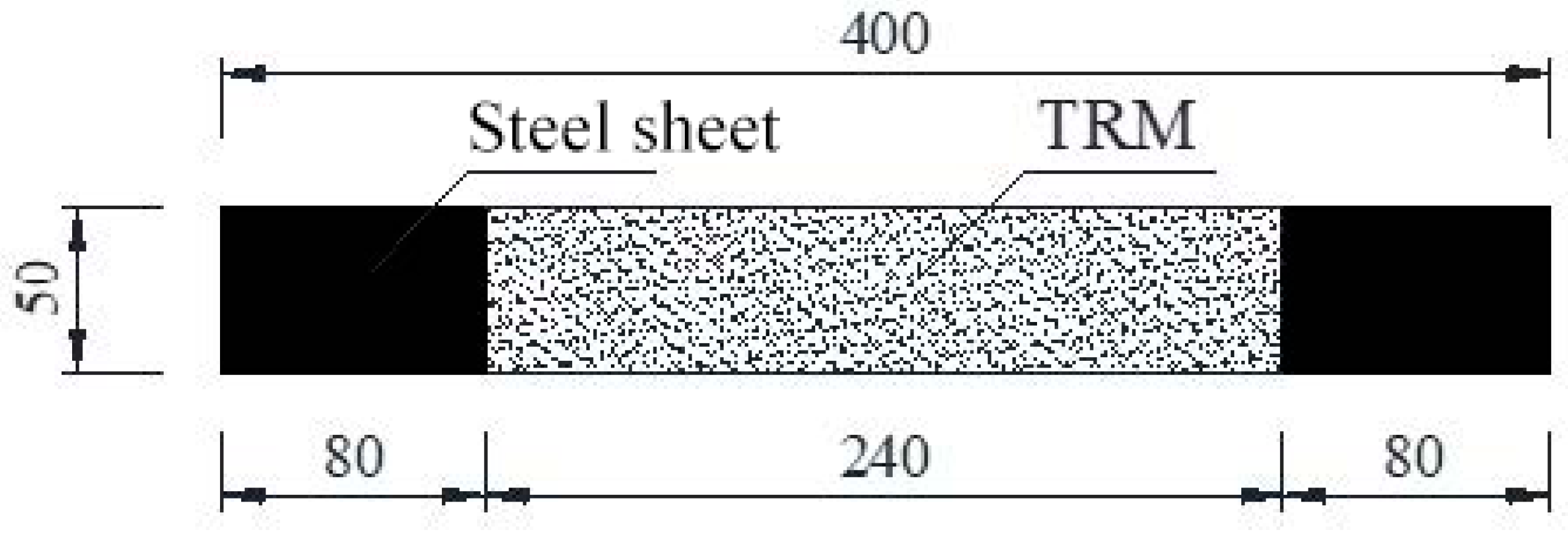
3.1. Design of Thin Slabs

This experimental study designed a total of six conditions, with fiber mesh sizes of 5 mm and 10 mm and a number of fiber mesh layers ranging from two to four layers. The designed thickness of the TRC thin slab used in the experiment was 20 mm. When using two layers of fiber mesh, the thickness of the upper and lower base concrete layers was 7 mm each, and the thickness of the matrix concrete between the two fiber mesh layers was 6 mm. When using three or four layers of fiber mesh, the fiber mesh was evenly distributed throughout the thickness of the slab: for the three-layer fiber mesh slab, and the thickness of the upper and lower matrix layers and the matrix layer between the fiber mesh was 5 mm each; for the four-layer fiber mesh slab, the thickness of the upper and lower matrix layers and the matrix layer between the fiber mesh was 4 mm each. After the specimens were formed and cut, they were placed in a SHBY 40B standard constant temperature and humidity curing box (Shaoxing Shang Yu Xiang Da Instrument Manufacturing Co., Ltd., Shaoxing, China) at a temperature of 21.3 °C and a humidity of 95% for a 28-day curing period.

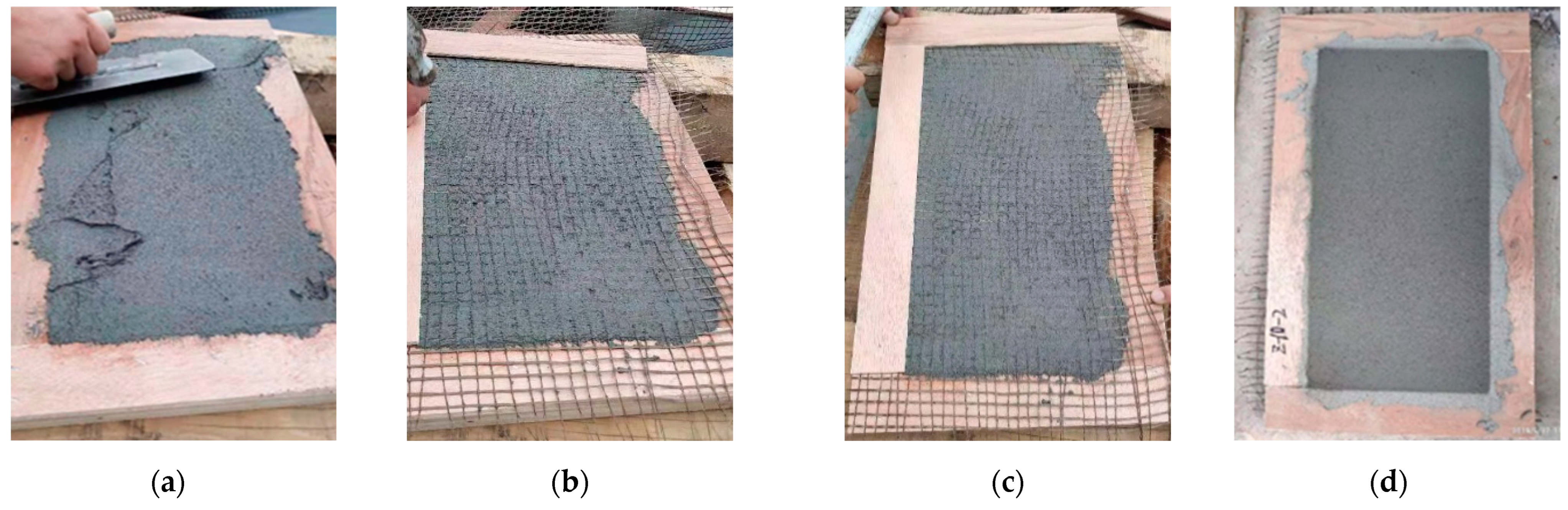
3.2. Preparation of Thin Slabs

To reduce the discreteness brought about by the casting process, the TRC thin slab specimens were cut from large slabs, with dimensions of 400 mm × 200 mm × 20 mm. Before testing, they were sawed into the required specimen sizes using a stone cutting machine, with dimensions of 400 mm × 50 mm × 20 mm (Figure 8). The gauge length of the specimen was 240 mm, and the width was 50 mm. Within the width range of the specimen, the single-layer fiber mesh must contain at least 10 bundles of fibers (5 mm fiber mesh) or 5 bundles of fibers (10 mm fiber mesh).
To ensure uniform dispersion of PVA fibers in the fine concrete matrix, the mixing method plays a crucial role. Extensive testing has verified that the semi-dry mixing method can achieve a more uniform distribution of chopped fibers in the concrete matrix without causing damage to the fibers themselves, thereby improving fiber utilization efficiency. When mixing the matrix concrete, first the cement and sand powder components are dry-mixed, as shown in Figure 9 (after mixing evenly, the water, water-reducing agent, and acrylic emulsion liquid components are combined and mixed uniformly, as shown in Figure 9b). Then, one-third of the mixture is added for wet mixing, using a handheld mixer to stir for about 2 min to initially moisten the sand surface (Figure 9c), preventing the sand surface friction from damaging the PVA fiber surface. Subsequently, the fibers are slowly, continuously, and evenly added to the mixture and stirred. Finally, the remaining liquid components are added and mixed for 2–3 min until the matrix has a certain level of fluidity, as shown in Figure 9d.
The casting method employs the layer-by-layer casting technique [50,51], taking the two-layer fiber mesh–reinforced concrete thin slab as an example. First, the formwork is placed horizontally, and the bottom layer of concrete (approximately 7 mm thick) is cast and smoothed. Then, the first layer of fiber mesh is laid on the concrete layer and pressed into it with a trowel to prevent deformation, after which it is fixed with the second layer of edge formwork. Subsequently, the second layer of matrix concrete (approximately 6 mm thick) is cast, and the second layer of fiber mesh is laid in the same manner as the first layer. This process continues until the last layer of matrix concrete is smoothed, completing the casting of the specimens, as shown in Figure 10.

3.3. Test Conditions

The test design parameters for the axial tensile test of TRC thin slabs are the number of fiber mesh layers and the mesh size of the fiber mesh. The specific test conditions and specimen numbers can be seen in Table 4. The specimen numbers are composed of letters and numbers, where “S” represents the mesh size of the fiber mesh and “F” represents the number of fiber mesh layers. For example, S5F2 indicates a TRC thin slab tensile specimen with a mesh size of 5 mm and two layers of fiber mesh.

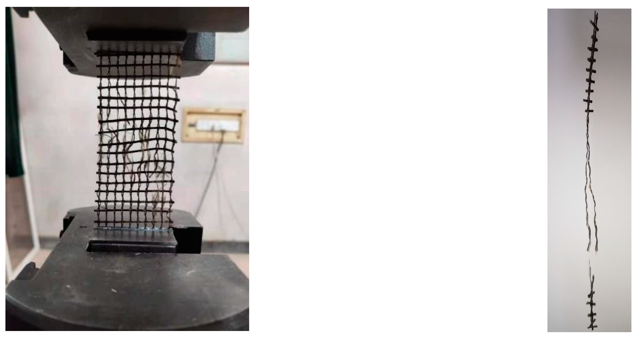
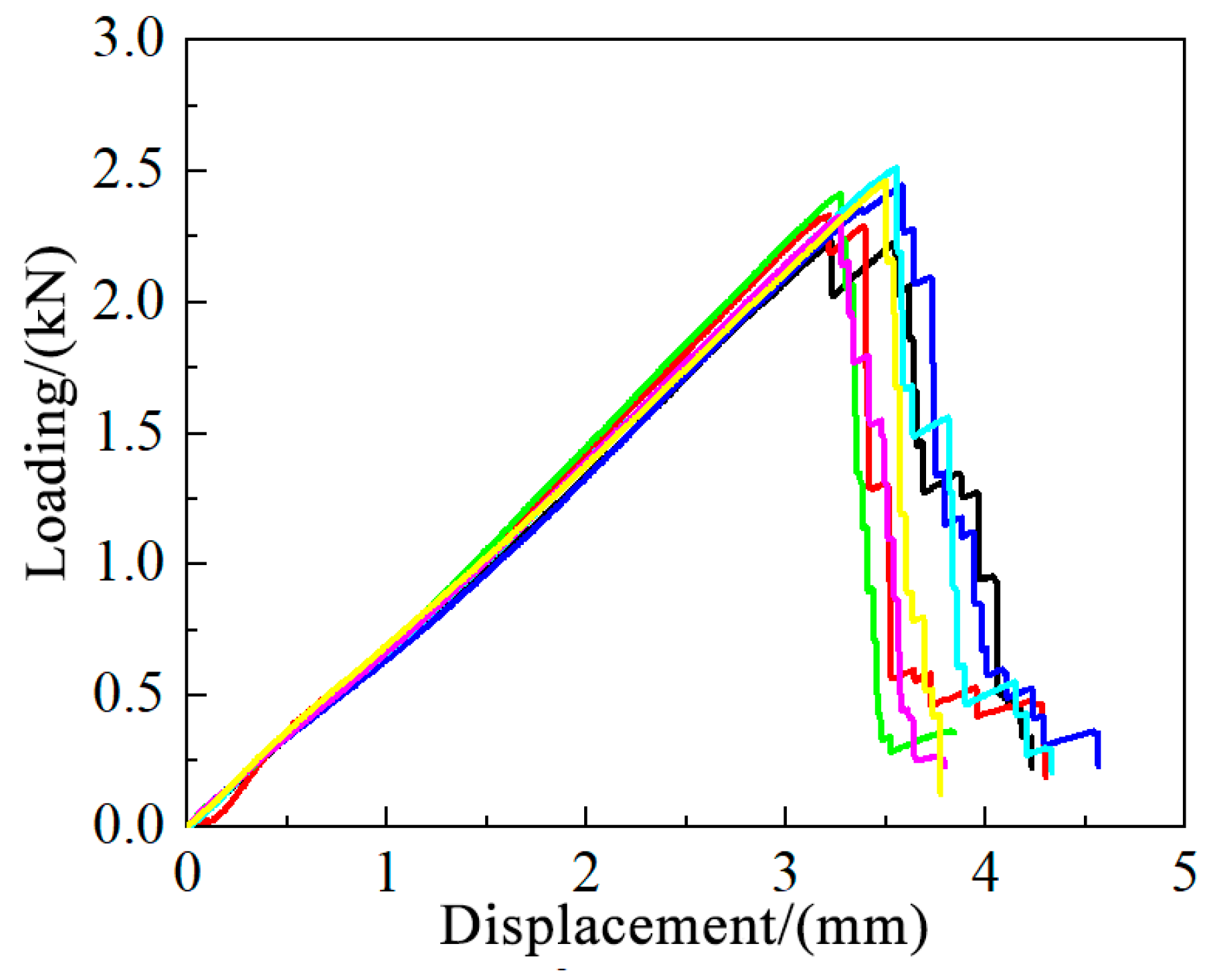
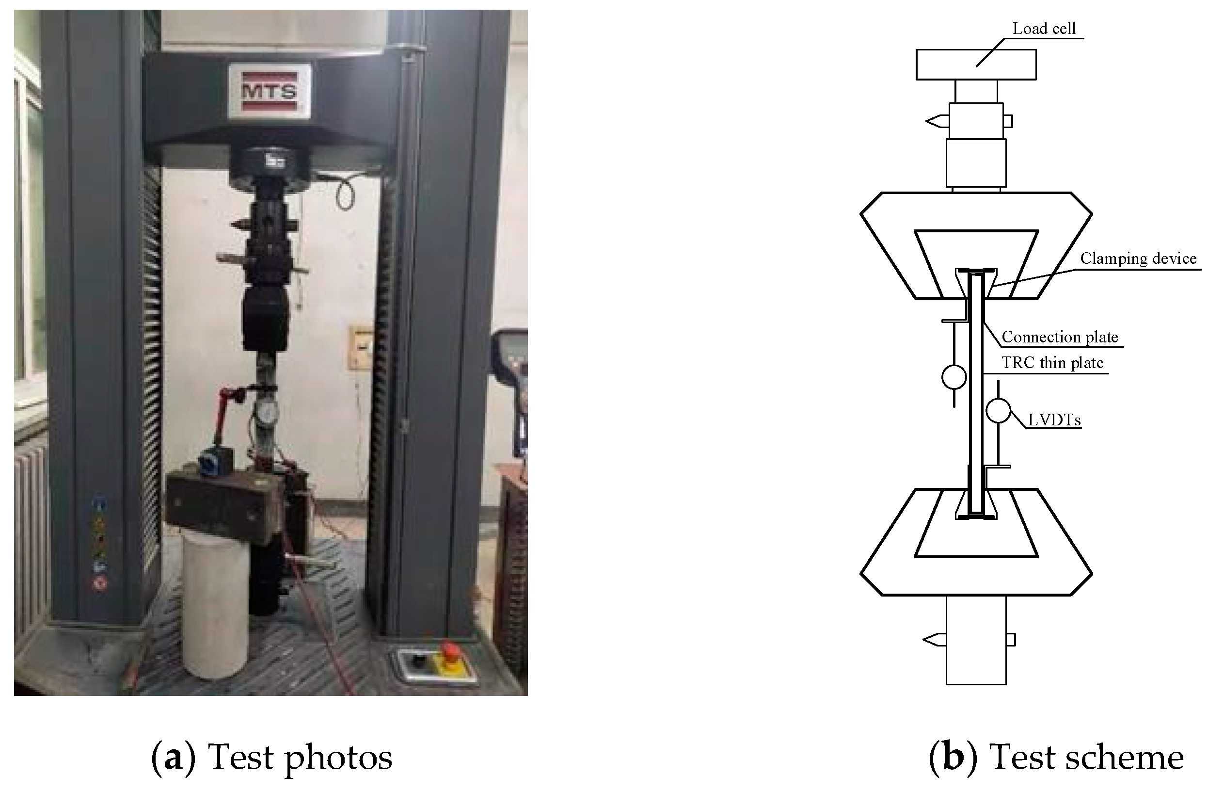
4. Test Method and Test Procedure

The uniaxial tensile test of the BTRC thin slab was conducted on an MTS electro-hydraulic servo testing machine, which has a maximum tensile force of 300 kN. The loading device for the test is shown in Figure 11a, and the measurement scheme and testing principle are illustrated in Figure 11b.
The loading method for the test is displacement-controlled loading, with a loading rate of 0.5 mm/min, and the gauge length of the specimen is 240 mm. The load is measured by the load cell integrated with the testing machine, and the deformation of the specimen is measured by displacement gauges installed on both sides of the specimen. Both the load and the specimen deformation are simultaneously collected by the JM3841 dynamic and static strain testing system, with a data collection frequency of 20 Hz. Stress is obtained by dividing the test load by the cross-sectional area of the specimen, and strain is obtained by dividing the deformation within the gauge length of the specimen by the gauge length itself. During the test, the crack development and the number of cracks in the specimen are observed and recorded, and the crack patterns are delineated with a marking pen.

5. Test Results and Analysis

The axial tensile load–deformation curve of TRC thin slabs can be divided into three stages [52,53], corresponding to the three stages of the stress–strain curve. Stage I (Linear Elastic Stage): in this stage, the load is borne by both the matrix concrete and the embedded fiber mesh, but since the concrete has not cracked, the fiber mesh plays a minor role, with the matrix concrete being the primary load bearer. The end of this stage is marked by the tensile stress on the specimen reaching the tensile strength of the concrete matrix, and the first crack appears on the surface of the TRC thin slab specimen. Stage II (Multi-Crack Development Stage): after the specimen has cracked, the fiber mesh begins to play its role. The bond force between the fiber mesh and the concrete matrix is the reason for the continued increase in load during this stage. Therefore, there is a continuous process of internal force redistribution between the fiber mesh and the concrete matrix, leading to the continuous generation of new cracks on the specimen surface. The slope of the curve in this stage depends on the bond strength between the two. Stage III (Failure Stage): when no new cracks appear on the specimen surface, the load is entirely borne by the fiber mesh. At this point, one of the cracks continuously expands under increasing load to become the main crack. The specimen fails when some of the radial fiber bundles at the main crack reach their tensile strength.

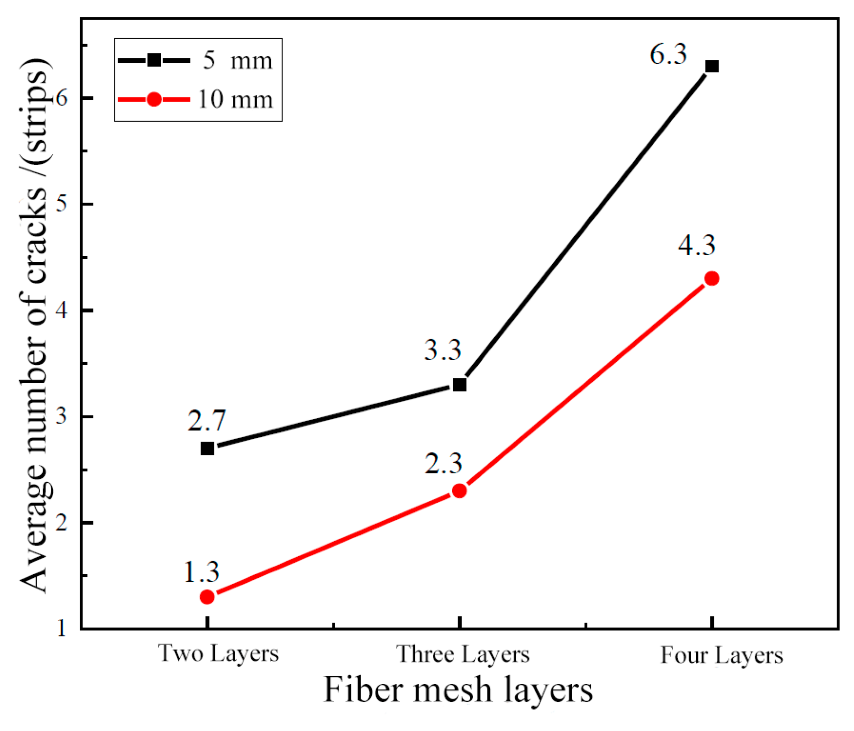
5.1. Test Phenomenon and Specimen Damage Mode

The overall damage patterns of the plain concrete thin slab specimens and the fiber mesh BTRC thin slab specimens are shown in Figure 12.
In the figure, the specimens from left to right contain zero, two, three, and four fiber mesh layers. When the specimen reaches its cracking strength, micro-cracks begin to appear in the specimen. However, due to the bonding action of the concrete matrix, the load-bearing capacity of the specimen does not immediately drop to zero, but undergoes a brief development process [54]. During this process, because of the bridging effect of the fiber mesh itself and the interaction between the fiber mesh and the internal PVA fibers [55], the propagation of these micro-cracks is restrained, allowing the specimen to continue bearing load. Specimens without fiber mesh configuration display only one macro-crack at failure, showing a “fail at first crack” failure mode. In contrast, specimens with fiber mesh configuration, as indicated by the failure pattern of the specimens, show an increasing trend in the number of cracks produced at failure with increasing numbers of fiber mesh layers. Particularly when the mesh size is 5 mm and a four-layer fiber mesh cloth is used, the crack development in the specimen is more substantial before reaching the tensile strength, resulting in a relatively larger ultimate tensile strain at failure, which greatly improves the ductility of the BTRC. When the number of fiber mesh layers is two to three, the number of cracks is fewer, and the growth is not significant; the crack development is limited after the specimen cracks, hence the improvement in ductility is not pronounced.
The number and spacing of cracks that appear during the tensile process of a specimen reflect the quality of the specimen’s strain hardening performance. The greater the number of cracks and the smaller the spacing, the better the strain hardening performance [56]. The crack patterns of specimens under six different conditions after tensile testing are shown in Figure 12. The statistics of crack numbers and spacing for each condition are presented in Table 5. According to the data in the table, as the number of mesh layers increases, the average number of cracks in the specimens increases, and the crack patterns of the specimens have greatly improved. Before the specimens reach their previous tensile strength, the cracks develop more fully.
The uniaxial tensile test results of specimens under each condition are shown in Table 6 and Table 7.

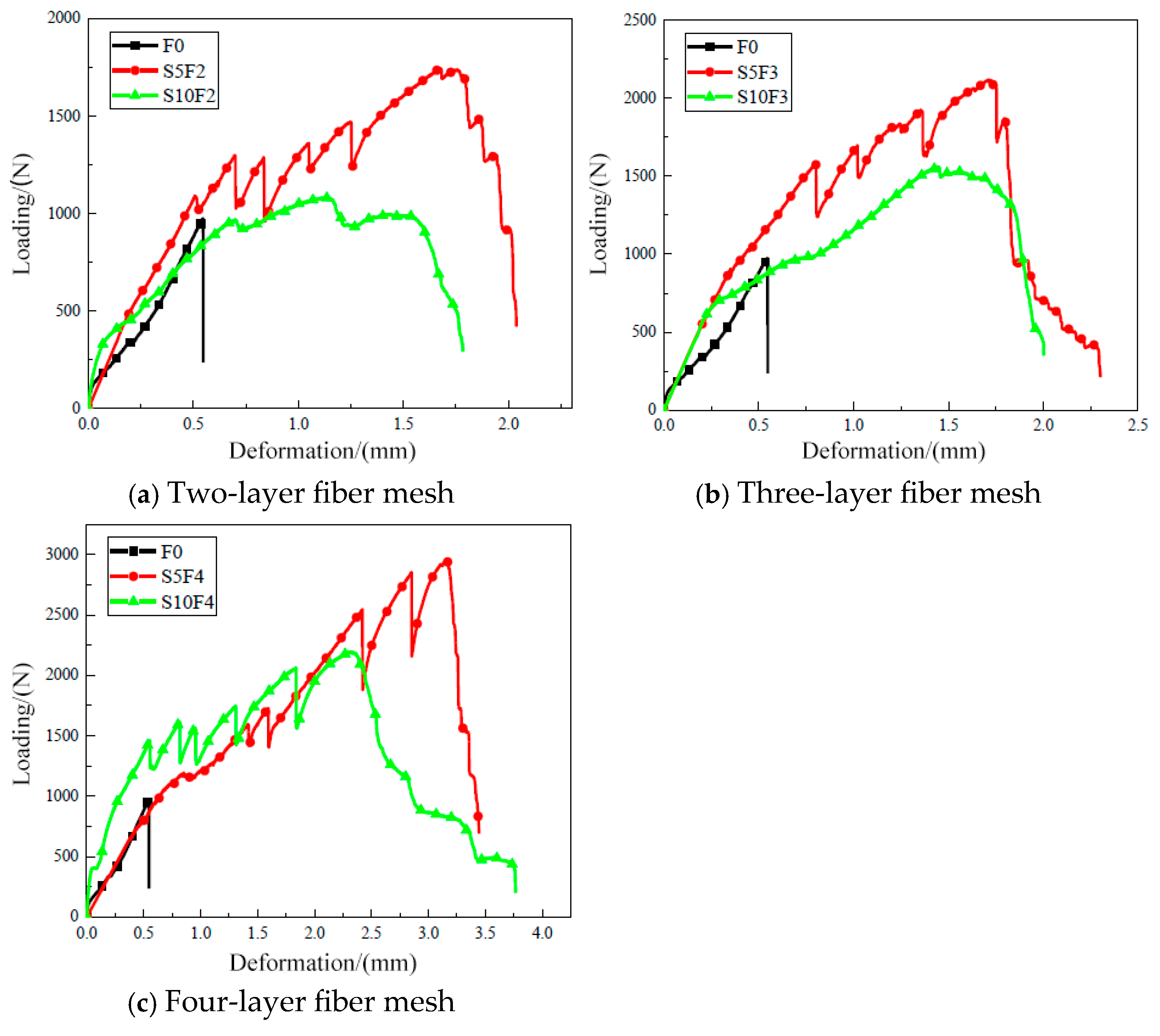
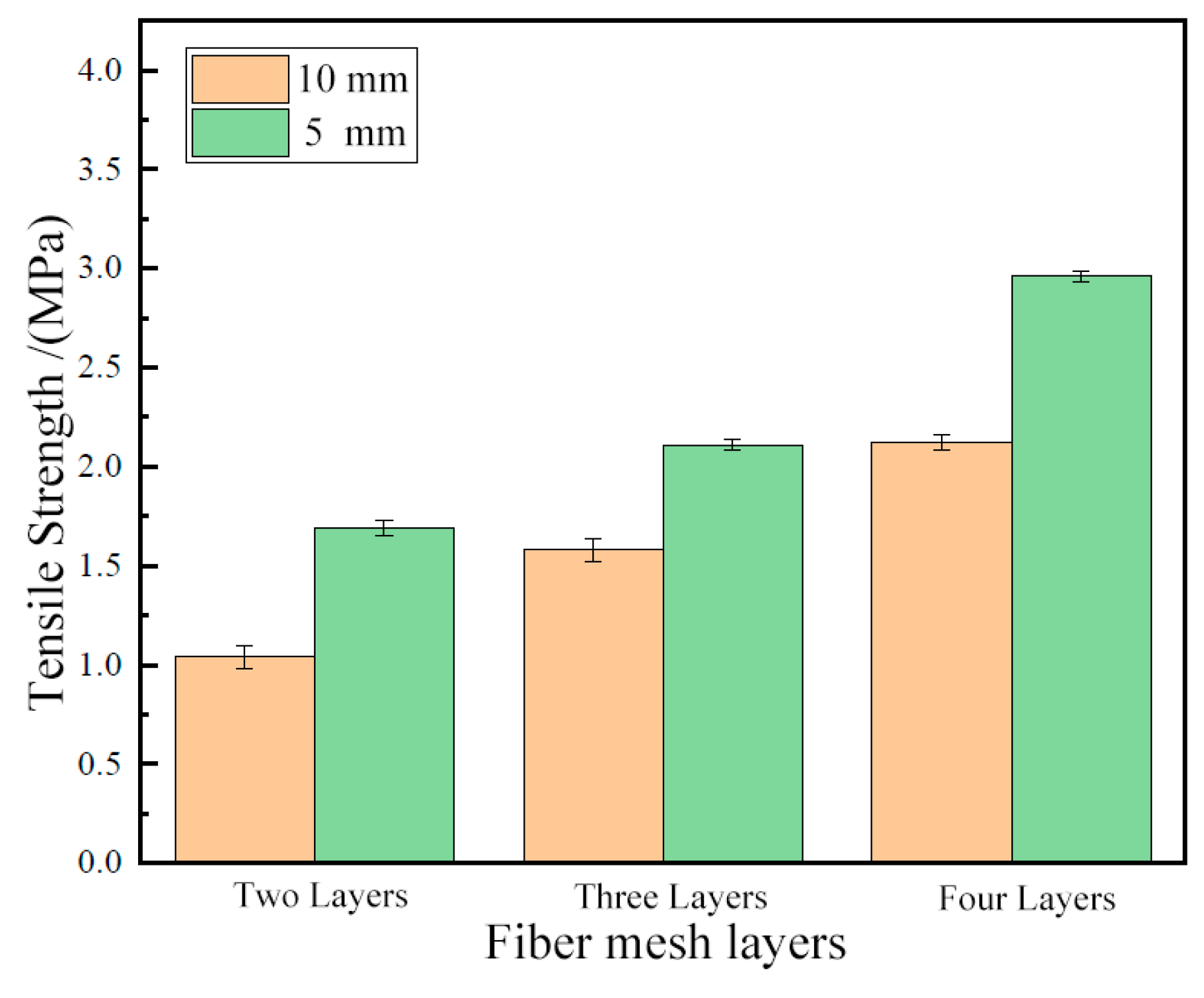
5.2. Effect of the Number of Fiber Mesh Layers on the Tensile Properties of BTRC Thin Slabs

Figure 13 shows the uniaxial tensile load–deformation curves for TRC thin slab specimens with different layers of fiber mesh. As can be seen from Figure 13, when the aperture size of the fiber mesh is 5 mm and the specimens are configured with two, three, and four layers of fiber mesh, the tensile strength (i.e., peak stress) increases by 67.33%, 108.91%, and 193.07%, respectively, compared to the specimens without fiber mesh, and the corresponding peak strains increase by 167.80%, 188.13%, and 413.56%, respectively. When the aperture size of the fiber mesh is 10 mm and the specimens are configured with two, three, and four layers of fiber mesh, the tensile strength increases by 2.97%, 56.44%, and 109.90%, respectively, compared to the specimens without fiber mesh, and the corresponding peak strains increase by 84.75%, 166.10%, and 298.31%, respectively. This indicates that, with the increase in the number of layers of fiber mesh, not only does the tensile strength of the BTRC thin slabs significantly improve, but their ductility (deformation corresponding to the peak load) also gradually enhances. Moreover, when the aperture size is 5 mm, or when the aperture size is 10 mm with more than three layers of fiber mesh, the specimens exhibit obvious strain-hardening behavior, meaning the stiffness of the specimens in Stage III is between that of Stage I and Stage II.

5.3. Effect of Mesh Size on the Tensile Properties of BTRC Thin Slabs

Figure 14 shows the uniaxial tensile load–deformation curves of BTRC thin slab specimens with different mesh sizes, where (a), (b), and (c) represent the load–deformation curves for specimens configured with two, three, and four layers of fiber mesh, respectively. Figure 15 compares the final tensile strengths of TRC thin slab specimens with different mesh sizes when configured with two, three, and four layers of fiber mesh.
Figure 14 and Figure 15 show that the specimens with a 5 mm fiber mesh configuration have higher tensile strength and corresponding peak tensile strain than those with a 10 mm fiber mesh configuration. Moreover, during the strain-hardening stage, the load increases more significantly. The main reasons are as follows. First, the 5 mm fiber mesh is more densely distributed in the cross-section of the specimen, resulting in a higher mesh ratio and enabling the specimen to bear higher loads during the multi-crack development stage. Additionally, the 5 mm fiber mesh has a larger contact area with the concrete matrix, leading to higher bond strength. To some extent, this prevents slippage between the fiber bundles and the concrete matrix after cracking, thus extending the time during which both materials share the load. When two to three layers of fiber mesh are included, the specimens with a 5 mm fiber mesh exhibit typical fluctuating polyline segments in the macro-crack development stage, indicating that more cracks are generated at this stage. From the perspective of crack distribution, the cracks are more evenly distributed. The specimens with a 10 mm fiber mesh only show fluctuating load-deformation curves when four layers are included, as shown in Figure 16, which compares the number of cracks for different mesh sizes with the same number of fiber mesh layers.
Figure 16 shows that, when the number of fiber mesh layers is the same, the specimens with a 5 mm fiber mesh configuration have a higher average number of cracks upon failure compared to those with a 10 mm fiber mesh configuration. This indicates that, with the same number of fiber mesh layers, the specimens with a 5 mm fiber mesh configuration exhibit a better crack pattern under uniaxial tension, demonstrating superior strain-hardening performance.

6. Theoretical Analysis of Tensile Properties of TRC Thin Slabs

6.1. Elastic Modulus and Cracking Stress

The theory of composite materials is often used to predict the mechanical properties of fiber-reinforced cement-based composites. The ratio of the cross-sectional area A t of the fiber mesh in the direction of applied force to the total cross-sectional area A of the TRC specimen is referred to as the mesh ratio [57], as shown in Equation (5).
ρ t = A t A
where ρ t is the mesh ratio of the specimen. A t is the cross-sectional area of the fiber mesh in the TRC thin slab specimen in the direction of force, in mm2. A is the cross-sectional area of the TRC thin slab specimen, in mm2.
The theoretical cross-sectional area of the fiber bundle calculated from Equation (1) is shown in Table 8.
Based on theoretical analysis of composite materials, the mechanical properties of TRC uniaxial tensile specimens before cracking are investigated. It is assumed that the TRC specimens meet the following basic assumptions [51] before tensile cracking: (1) the fiber mesh and the matrix concrete only exhibit elastic deformation when subjected to tension; (2) there is a good bond between the fiber mesh and the matrix concrete; (3) the deformation amount of the fiber mesh, concrete, and TRC components is the same when subjected to tension; and (4) Poisson’s ratio of the fiber mesh and concrete is neglected.
From the above basic assumptions, the elastic modulus of the specimen can be derived, as shown in Equation (6):
E t I = E m 1 ρ t + E t ρ t = E m [ 1 + ( E t E m 1 ) ρ t ]
Then, the cracking stress of the specimen can be derived from Equation (6), as shown in Equation (7):
σ c r = f t m [ 1 + ( E t E m 1 ) ρ t ]
where E t I represents the elastic modulus of the TRC tensile specimen before cracking, in GPa. σ c r is the cracking stress of the TRC tensile specimen, in MPa. E m and E t are the elastic modulus of the matrix concrete and fiber mesh, respectively, in GPa. f t m is the tensile strength of the matrix concrete, in MPa.
It can be seen from Equation (6) that the elastic modulus of the TRC tensile specimen mainly depends on the elastic modulus of the matrix concrete and is positively correlated with the ratio of the fiber mesh to the elastic modulus of the matrix concrete. The maximum mesh ratio of the fiber mesh (i.e., when the mesh size of the fiber mesh is 5 mm, and four layers of fiber mesh are included) is 0.89%, which is a relatively small proportion compared to the matrix concrete. Therefore, the contribution of the fiber mesh to the elastic modulus of the TRC tensile specimen is very small. Consequently, it can be concluded that the elastic modulus of the TRC tensile specimen before cracking is approximately equal to the elastic modulus of the matrix concrete.
It can be seen from Equation (7) that the cracking stress of the TRC tensile specimen mainly depends on the tensile strength of the matrix concrete and is positively correlated with the ratio of the fiber mesh to the elastic modulus of the matrix concrete. From the above analysis, it can be seen that the number of layers of fiber mesh has little effect on the cracking stress of the TRC tensile specimen. However, as indicated by the load–deformation curve, with the increase in the number of fiber mesh layers (i.e., the mesh ratio), the cracking stress of the TRC tensile specimen decreased to a certain degree. This may be because the addition of the fiber mesh has a certain weakening effect on the cross-section of the TRC tensile specimen [57].

6.2. Tensile Strength of TRC Thin Slabs

For TRC thin slabs tensile specimens, after the number of cracks on the specimen reaches a saturated state (i.e., at the end of Stage II), the width of one of the cracks on the specimen will gradually increase, developing into the main crack, until the fibers break and the specimen is completely destroyed. For this test, the most ideal failure mode is that the fiber mesh is completely ruptured. From this, it can be understood that the apparent tensile strength of the TRC tensile specimen is:
σ u = σ t u ρ t ,
where σ t u is the tensile strength of the fiber mesh strip, which is calculated by Equation (9).
σ t u = P A t u
where P is the failure load measured by the tensile test of the fiber woven mesh, in N. A t u is the cross-sectional area of the fiber woven mesh strip, mm2, and the value of this test is A t × 10 (5 mm fiber mesh) or A t × 5 (10 mm fiber mesh).
Based on Deng [58] and Kouris [7], it is known that, during the calculation of fiber mesh–reinforced concrete, there is a certain degree of load-bearing capacity attenuation due to the complex internal stress effects within the fiber mesh. In order to obtain more accurate calculation values, this study proposes a reduction coefficient β for the load-bearing capacity of the fiber mesh, as shown in Equation (10).
β = e ρ t Q
where Q is related to the fiber mesh size, and is 0.6 (5 mm fiber mesh) or 0.5 (10 mm fiber mesh).
The tensile strength of the final TRC tensile specimen is calculated as follows:
σ u = β σ t u ρ t
The calculation of the mesh ratio and tensile strength for each TRC tensile specimen under various conditions using Equation (11) is shown in Table 9.
The comparison results in Table 9 show that the theoretical values are relatively close to the experimental values, with an average ratio of theoretical to experimental values of 1.14, which is considered a good computational result. This indicates that the calculation formula has a high degree of accuracy. During the loading process, the fiber mesh cannot fully exert its effects, and there will be a certain degree of reduction. The higher the mesh ratio, the more significant this impact becomes. Therefore, the calculated values for the S5F3 and S5F4 specimens are on the high side, which will be a primary focus for further refinement in our subsequent research.

7. Conclusions

This study investigates the effects of two mesh sizes, 5 mm × 5 mm and 10 mm × 10 mm, and two to four layers of basalt fiber mesh on the mechanical properties of BTRC thin slabs through uniaxial tensile tests. According to the research, several conclusions can be drawn regarding the tensile characteristics of Basalt Textile–Reinforced Fine Aggregate Concrete (BTRFAC) thin slabs:
(1) Improved Tensile Strength and Ductility: The integration of basalt fiber mesh significantly enhances both the tensile strength and deformation characteristics of thin concrete slabs. This improvement is especially pronounced when multiple layers of fiber mesh are utilized, resulting in increased ductility and strain-hardening capabilities;
(2) Influence of Mesh Size: A finer mesh size of 5 mm × 5 mm demonstrates superior performance compared to a coarser 10 mm × 10 mm mesh in terms of tensile strength, peak strain, and crack distribution. The finer mesh facilitates better crack management and a more uniform distribution of stress within the concrete matrix;
(3) Optimal Layer Count: The quantity of fiber mesh layers is critical in improving tensile properties. Specimens reinforced with three to four layers of basalt textile showed significant enhancements in tensile strength and exhibited more favorable crack patterns than those with fewer layers;
(4) Theoretical Calculation of Load-Bearing Capacity: an equation for calculating the tensile load-bearing capacity of BTRFCA thin slabs was proposed, and the average ratio of the theoretical value to the test value was 1.14, with relatively small error;
(5) Implications for Design and Application: These insights offer essential information for the design and implementation of basalt fiber mesh–reinforced concrete thin slabs. By optimizing both the mesh size and the number of layers, engineers can create concrete elements that exhibit enhanced tensile performance and durability.

8. Discussion

According to the experimental results, BTRFAC demonstrates promising potential as a primary development direction for fiber textile–reinforced concrete. BTRFAC effectively overcomes the shortcomings of conventional concrete materials. When applied to structural component reinforcement, it can fully utilize its mechanical properties to enhance reinforcement effectiveness. This paper does not cover research on structural component reinforcement. Future studies will focus on investigating BTRFAC-strengthened shear walls, beams, and slabs, with particular emphasis on developing load-bearing capacity calculation formulas, to provide valuable data references for structural reinforcement engineering practices.

Author Contributions

Conceptualization, L.W. and Z.D.; methodology, Z.D.; software, L.W.; validation, Z.D.; formal analysis, L.W.; investigation, Z.D.; resources, Z.D.; data curation, L.W.; writing—original draft preparation, L.W.; writing—review and editing, Z.D.; visualization, L.W.; supervision, Z.D.; project administration, Z.D.; funding acquisition, Z.D. All authors have read and agreed to the published version of the manuscript.

Funding

This research was funded by the National Natural Science Foundation of China (No.51578021 and 51378032) and the Key Science and Technology Projects of Beijing Natural Science Foundation (No. KZ201810005008).

Informed Consent Statement

Informed consent was obtained from all subjects involved in the study. The study was conducted in accordance with the Declaration of Helsinki, with due regard for ethical standards, and the protocol was approved by the Ethics Committee of Construction Management Department of Beijing University of Technology (BGUTEC202505066) on 30 April 2025.

Data Availability Statement

The original contributions presented in this study are included in this article; further inquiries can be directed to the corresponding author.

Acknowledgments

The authors would like to thank all the anonymous reviewers and editors for their efforts. Additionally, the authors would like to thank their institutions for their support.

Conflicts of Interest

The authors declare no conflicts of interest.

Symbols and Acronyms

A t the theoretical cross-sectional area of a single fiber bundle, in mm2.
T e x the linear density of the fiber, in g/km.
ρ v the volume density of the fiber, in g/cm3.
σ t u the measured tensile strength of the fiber mesh strip, in MPa.
P the measured failure load from the test, in N.
n the number of fiber bundles within the width of the fiber mesh strip.
E t the tensile elastic modulus of the fiber mesh strip.
P the load difference intercepted on the initial linear segment of the tensile stress–strain curve from the test, in N.
L the gauge length of the specimen, in mm.
L the elongation of the specimen’s gauge length relative to ∆P, in mm.
ε t the elongation rate at the failure of the specimen, in %.
ρ t the mesh ratio of the specimen.
A t the cross-sectional area of the fiber mesh in the TRC thin slab specimen in the direction of force, in mm2.
A the cross-sectional area of the TRC thin slab specimen, in mm2.
E t I the elastic modulus of the TRC tensile specimen before cracking, in GPa.
σ c r the cracking stress of the TRC tensile specimen, in MPa.
E m the elastic modulus of the matrix concrete, in GPa.
E t the elastic modulus of the fiber mesh, in GPa.
f t m the tensile strength of the matrix concrete, in MPa.
σ t u the tensile strength of the fiber mesh strip, in MPa.
P the failure load measured by the tensile test of the fiber woven mesh, in N.
A t u the cross-sectional area of the fiber woven mesh strip, mm2.
β the load-bearing capacity of the fiber mesh.
Q related to the fiber mesh size; 0.6 (5 mm fiber mesh) or 0.5 (10 mm fiber mesh).
BTRCBasalt Fiber Textile–Reinforced Concrete.
TRCTextile-Reinforced Concrete.
BTRMBasalt Fiber Mesh–Reinforced Mortar.
BTRLMBasalt Fiber Mesh–Reinforced Lime Mortar.
BFRCMBasalt Fiber Mesh–Reinforced Cement Matrix.
BTRFACBasalt Textile–Reinforced Fine-Aggregate Concrete.

References

  1. Wang, J.; Yu, D.; Zeng, C.; Ji, X.; Ye, L.; Zhou, P.; Zhao, S. Effect of Textile Layers and Hydroxypropyl Methylcellulose on Flexural Behavior of TRLC Thin Plates. Buildings 2024, 14, 924. [Google Scholar] [CrossRef]
  2. Yılmaz, M.C. Textile Types, Number of Layers and Wrapping Types Effect on Shear Strengthening of Reinforced Concrete Beams with Textile-Reinforced Mortar versus Carbon-Fiber-Reinforced Polymer. Buildings 2023, 13, 2744. [Google Scholar] [CrossRef]
  3. Hartig, J.; Häußler-Combe, U.; Schicktanz, K. Influence of Bond Properties on the Tensile Behaviour of Textile Reinforced Concrete. Cem. Concr. Compos. 2008, 30, 898–906. [Google Scholar] [CrossRef]
  4. Valeri, P.; Fernàndez Ruiz, M.; Muttoni, A. Tensile Response of Textile Reinforced Concrete. Constr. Build. Mater. 2020, 258, 119517. [Google Scholar] [CrossRef]
  5. Contamine, R.; Si Larbi, A.; Hamelin, P. Identifying the Contributing Mechanisms of Textile Reinforced Concrete (TRC) in the Case of Shear Repairing Damaged and Reinforced Concrete Beams. Eng. Struct. 2013, 46, 447–458. [Google Scholar] [CrossRef]
  6. Butler, M.; Mechtcherine, V.; Hempel, S. Experimental Investigations on the Durability of Fibre–Matrix Interfaces in Textile-Reinforced Concrete. Cem. Concr. Compos. 2009, 31, 221–231. [Google Scholar] [CrossRef]
  7. Kouris, L.A.S.; Triantafillou, T.C. State-of-the-Art on Strengthening of Masonry Structures with Textile Reinforced Mortar (TRM). Constr. Build. Mater. 2018, 188, 1221–1233. [Google Scholar] [CrossRef]
  8. Giese, A.C.H.; Giese, D.N.; Dutra, V.F.P.; Da Silva Filho, L.C.P. Flexural Behavior of Reinforced Concrete Beams Strengthened with Textile Reinforced Mortar. J. Build. Eng. 2021, 33, 101873. [Google Scholar] [CrossRef]
  9. Koutas, L.N.; Papakonstantinou, C.G. Flexural Strengthening of RC Beams with Textile-Reinforced Mortar Composites Focusing on the Influence of the Mortar Type. Eng. Struct. 2021, 246, 113060. [Google Scholar] [CrossRef]
  10. Signorini, C.; Sola, A.; Nobili, A. Hierarchical Composite Coating for Enhancing the Tensile Behaviour of Textile-Reinforced Mortar (TRM). Cem. Concr. Compos. 2023, 140, 105082. [Google Scholar] [CrossRef]
  11. Venigalla, S.G.; Nabilah, A.B.; Mohd Nasir, N.A.; Safiee, N.A.; Abd Aziz, F.N.A. Textile-Reinforced Concrete as a Structural Member: A Review. Buildings 2022, 12, 474. [Google Scholar] [CrossRef]
  12. Xie, W.; Sheng, J.; Yu, Z.; Li, Y.; Dou, G. Flexural Behavior of Corroded RC Beams Strengthened by Textile-Reinforced Concrete. Buildings 2023, 13, 2902. [Google Scholar] [CrossRef]
  13. Schladitz, F.; Frenzel, M.; Ehlig, D.; Curbach, M. Bending Load Capacity of Reinforced Concrete Slabs Strengthened with Textile Reinforced Concrete. Eng. Struct. 2012, 40, 317–326. [Google Scholar] [CrossRef]
  14. Du, Y.; Zhang, X.; Zhou, F.; Zhu, D.; Zhang, M.; Pan, W. Flexural Behavior of Basalt Textile-Reinforced Concrete. Constr. Build. Mater. 2018, 183, 7–21. [Google Scholar] [CrossRef]
  15. Halvaei, M.; Jamshidi, M.; Latifi, M.; Ejtemaei, M. Experimental Investigation and Modelling of Flexural Properties of Carbon Textile Reinforced Concrete. Constr. Build. Mater. 2020, 262, 120877. [Google Scholar] [CrossRef]
  16. Papanicolaou, C.G.; Triantafillou, T.C.; Papathanasiou, M.; Karlos, K. Textile Reinforced Mortar (TRM) versus FRP as Strengthening Material of URM Walls: Out-of-Plane Cyclic Loading. Mater. Struct. 2008, 41, 143–157. [Google Scholar] [CrossRef]
  17. Tetta, Z.C.; Koutas, L.N.; Bournas, D.A. Shear Strengthening of Full-Scale RC T-Beams Using Textile-Reinforced Mortar and Textile-Based Anchors. Compos. Part B Eng. 2016, 95, 225–239. [Google Scholar] [CrossRef]
  18. Guo, L.; Deng, M.; Chen, H.; Li, R.; Ma, X.; Zhang, Y. Experimental Study on Pre-Damaged RC Beams Shear-Strengthened with Textile-Reinforced Mortar (TRM). Eng. Struct. 2022, 256, 113956. [Google Scholar] [CrossRef]
  19. Koutas, L.N.; Bournas, D.A. Flexural Strengthening of Two-Way RC Slabs with Textile-Reinforced Mortar: Experimental Investigation and Design Equations. J. Compos. Constr. 2017, 21, 04016065. [Google Scholar] [CrossRef]
  20. Wan, C.; Wang, J.; Wang, S.; Ji, X.; Peng, Y.; Zhang, H. Tensile Behavior of Basalt Textile Reinforced Concrete: Effect of Test Setups and Textile Ratios. Materials 2022, 15, 8975. [Google Scholar] [CrossRef]
  21. Guo, S.; Ren, J.; Yang, T.; Rahman, M.Z.; Shi, C.; Zhu, D. Influences of Surface Treatment on the Mechanical Performances of Carbon and Basalt Textiles-Reinforced Concretes under Harsh Environments. Compos. Part B Eng. 2022, 246, 110195. [Google Scholar] [CrossRef]
  22. Zhang, X.; Wang, X.; Liang, X.; Zhao, C.; Chen, Z.; Zhang, Y.; Zhou, J.; Wu, Z. Experimental Study and Theoretical Analysis on Tensile Properties of Concrete Reinforced with Different Polymer-Impregnated Basalt Textiles. J. Build. Eng. 2024, 87, 109003. [Google Scholar] [CrossRef]
  23. Pham, H.H.; Dinh, N.H.; Kim, S.-H.; Park, S.-H.; Choi, K.-K. Tensile Behavioral Characteristics of Lightweight Carbon Textile-Reinforced Cementitious Composites. J. Build. Eng. 2022, 57, 104848. [Google Scholar] [CrossRef]
  24. Ho, H.; Nguyen, H.C.; Dinh, H.T.; Ngo, D.Q.; Le, D.D. Experimental Study on the Tensile Strength Degradation of Curved Alkali Resistant Glass and Carbon Textile as Concrete Reinforcement under Complex Loading. Case Stud. Constr. Mater. 2023, 18, e01947. [Google Scholar] [CrossRef]
  25. Zhang, X.; Yin, R.; Chen, Y.; Lou, C. Experimental Study on the Axial Tensile Properties of Polypropylene Fiber Reinforced Concrete. Sci. Rep. 2023, 13, 16383. [Google Scholar] [CrossRef]
  26. Li, Z.; Jiang, Z.; Fang, Z.; Wang, Z.; Fang, Y. High-Temperature Axial Tensile Property and Fire Resisting Performance of CFRP Strand Cable. Constr. Build. Mater. 2024, 421, 135746. [Google Scholar] [CrossRef]
  27. Zhao, J.; Li, H.B. Experimental Determination of Dynamic Tensile Properties of a Granite. Int. J. Rock Mech. Min. Sci. 2000, 37, 861–866. [Google Scholar] [CrossRef]
  28. Qiu, Y.; Batchelor, S.D.; Jack, P.R.; McCord, M.G. Estimation of the Axial Tensile Modulus of a Particle-Reinforced Composite Fiber with Variable Radius. Compos. Sci. Technol. 2000, 60, 2731–2737. [Google Scholar] [CrossRef]
  29. Dong, Z.; Deng, M.; Zhang, C.; Zhang, Y.; Sun, H. Tensile Behavior of Glass Textile Reinforced Mortar (TRM) Added with Short PVA Fibers. Constr. Build. Mater. 2020, 260, 119897. [Google Scholar] [CrossRef]
  30. Suh, J.-I.; Park, S.-W.; Kim, K.-M. Tensile Behavior Assessment of Grid-Type CFRP Textile-Reinforced Mortar with Different Design Variables. Materials 2024, 17, 6049. [Google Scholar] [CrossRef]
  31. Ghannoum, M.; Shamoun, L.; Nasr, D.; Assaad, J.J.; Riahi, H.; Khatib, J. Efficiency of Stochastic Finite Element Random Fields and Variables to Predict Shear Strength of Fiber-Reinforced Concrete Beams Without Stirrups. Buildings 2025, 15, 721. [Google Scholar] [CrossRef]
  32. Assaad, J.J.; Khayat, K.H. Form Pressure Characteristics of Self-Consolidating Concrete Used in Repair. Cem. Concr. Compos. 2021, 122, 104118. [Google Scholar] [CrossRef]
  33. Shiping, Y.; Boxue, W.; Chenxue, Z.; Shuang, L. Bond Performance between Textile Reinforced Concrete (TRC) and Brick Masonry under Conventional Environment. Structures 2022, 36, 392–403. [Google Scholar] [CrossRef]
  34. Khalil, N.; Assaad, J.J. Bond Properties between Smooth Carbon Fibre-Reinforced Polymer Bars and Ultra-High Performance Concrete Modified with Polymeric Latexes and Fibres. Eur. J. Environ. Civ. Eng. 2022, 26, 6211–6228. [Google Scholar] [CrossRef]
  35. Jiang, J.; Jiang, C.; Li, B.; Feng, P. Bond Behavior of Basalt Textile Meshes in Ultra-High Ductility Cementitious Composites. Compos. Part B Eng. 2019, 174, 107022. [Google Scholar] [CrossRef]
  36. Zhang, X.; Wang, X.; Liang, X.; Zhao, C.; Wu, Z. Experimental Study on the Durability of Polymer-Impregnated Basalt Textile Applied as Concrete Reinforcement. Polym. Compos. 2022, 43, 3498–3518. [Google Scholar] [CrossRef]
  37. Monaldo, E.; Nerilli, F.; Vairo, G. Basalt-Based Fiber-Reinforced Materials and Structural Applications in Civil Engineering. Compos. Struct. 2019, 214, 246–263. [Google Scholar] [CrossRef]
  38. Jagadeesh, P.; Rangappa, S.M.; Siengchin, S. Basalt Fibers: An Environmentally Acceptable and Sustainable Green Material for Polymer Composites. Constr. Build. Mater. 2024, 436, 136834. [Google Scholar] [CrossRef]
  39. Fang, L.; Zhou, Y.; Yi, D.; Yi, W. Experimental Study on Flexural Capacity of Corroded RC Slabs Reinforced with Basalt Fiber Textile. Appl. Sci. 2020, 11, 144. [Google Scholar] [CrossRef]
  40. Zhang, X.; He, W.; Zhang, Y.; Chen, C.; Wu, X. Tensile Behavior of Basalt-Fiber-Grid-Reinforced Mortar before and after Exposure to Elevated Temperature. Buildings 2022, 12, 2269. [Google Scholar] [CrossRef]
  41. Meriggi, P.; Caggegi, C.; Gabor, A.; De Felice, G. Shear-Compression Tests on Stone Masonry Walls Strengthened with Basalt Textile Reinforced Mortar (TRM). Constr. Build. Mater. 2022, 316, 125804. [Google Scholar] [CrossRef]
  42. Prasath, C.R.; Jayaguru, C.; Arunachelam, N. Cyclic Performance of Reinforced Concrete Columns Strengthened with Basalt-Fibre-Reinforced Cementitious Matrix (BFRCM). Buildings 2024, 14, 3496. [Google Scholar] [CrossRef]
  43. Zhu, D.; Mobasher, B.; Rajan, S.D. Dynamic Tensile Testing of Kevlar 49 Fabrics. J. Mater. Civ. Eng. 2011, 23, 230–239. [Google Scholar] [CrossRef]
  44. GB/T 3362-2005; Test Methods for Tensile Properties of Carbon Fiber Multifilament. China Building Industry Press: Beijing, China, 2017.
  45. Jabbour, R.; Assaad, J.J.; Hamad, B. Cost-to-Performance Assessment of Polyvinyl Alcohol Fibers in Concrete Structures. Mech. Adv. Mater. Struct. 2022, 29, 2973–2983. [Google Scholar] [CrossRef]
  46. Assaad, J.J. Development and Use of Polymer-Modified Cement for Adhesive and Repair Applications. Constr. Build. Mater. 2018, 163, 139–148. [Google Scholar] [CrossRef]
  47. Feng, S.; Xiao, H.; Geng, J. Bond Strength between Concrete Substrate and Repair Mortar: Effect of Fibre Stiffness and Substrate Surface Roughness. Cem. Concr. Compos. 2020, 114, 103746. [Google Scholar] [CrossRef]
  48. Contamine, R.; Si Larbi, A.; Hamelin, P. Contribution to Direct Tensile Testing of Textile Reinforced Concrete (TRC) Composites. Mater. Sci. Eng. A 2011, 528, 8589–8598. [Google Scholar] [CrossRef]
  49. JGJ/T 70-2009; Standard for Test Method of Basic Properties of Construction Mortar. China Building Industry Press: Beijing, China, 2009.
  50. Kong, K.; Mesticou, Z.; Michel, M.; Si Larbi, A.; Junes, A. Comparative Characterization of the Durability Behaviour of Textile-Reinforced Concrete (TRC) under Tension and Bending. Compos. Struct. 2017, 179, 107–123. [Google Scholar] [CrossRef]
  51. Mesticou, Z.; Bui, L.; Junes, A.; Si Larbi, A. Experimental Investigation of Tensile Fatigue Behaviour of Textile-Reinforced Concrete (TRC): Effect of Fatigue Load and Strain Rate. Compos. Struct. 2017, 160, 1136–1146. [Google Scholar] [CrossRef]
  52. Colombo, I.G.; Magri, A.; Zani, G.; Colombo, M.; Di Prisco, M. Erratum to: Textile Reinforced Concrete: Experimental Investigation on Design Parameters. Mater. Struct. 2013, 46, 1953–1971. [Google Scholar] [CrossRef]
  53. Larrinaga, P.; Chastre, C.; Biscaia, H.C.; San-José, J.T. Experimental and Numerical Modeling of Basalt Textile Reinforced Mortar Behavior under Uniaxial Tensile Stress. Mater. Des. 2014, 55, 66–74. [Google Scholar] [CrossRef]
  54. Baloch, W.L.; Siad, H.; Lachemi, M.; Sahmaran, M. A Review on the Durability of Concrete-to-Concrete Bond in Recent Rehabilitated Structures. J. Build. Eng. 2021, 44, 103315. [Google Scholar] [CrossRef]
  55. Zhang, X.; Du, M.; Fang, H.; Li, B.; Zhao, P.; Zhai, K.; Yao, X.; Du, X.; Shi, M.; Ma, D. Study on the Shear Strength and Damage Constitutive Model of the Contact Surface between PVA Fiber-Enhanced Cement Mortar and Concrete. Constr. Build. Mater. 2023, 400, 132571. [Google Scholar] [CrossRef]
  56. Li, L.; Cai, Z.; Yu, K.; Zhang, Y.X.; Ding, Y. Performance-Based Design of All-Grade Strain Hardening Cementitious Composites with Compressive Strengths from 40 MPa to 120 MPa. Cem. Concr. Compos. 2019, 97, 202–217. [Google Scholar] [CrossRef]
  57. Xu, S.L.; Yan, Z.Q. Mechanical Properties of Textile Reinforced Concrete Plate at Low Textile Ratios. Acta Mater. Compos. Sin. 2011, 28, 206–213. [Google Scholar] [CrossRef]
  58. Deng, Z.; Xu, J. Uniaxial tensile behavior of engineering cementitious composite reinforced with fiber textile grid and steel wire mesh. Mech. Adv. Mater. Struct. 2024, 32, 1853–1867. [Google Scholar] [CrossRef]
Figure 1. Basalt mesh.
Buildings 15 01540 g001
Figure 2. Specimens of basalt fiber bundles and mesh strips.
Buildings 15 01540 g002
Figure 3. Tensile test of basalt fiber bundles and fiber mesh strip.
Buildings 15 01540 g003
Figure 4. Failure modes of basalt fiber bundles and mesh strips.
Buildings 15 01540 g004
Figure 5. Tensile load versus displacement curve of basalt mesh strips. Note: Different colors represent parallel specimens of basalt mesh strips.
Buildings 15 01540 g005
Figure 6. PVA fibers.
Buildings 15 01540 g006
Figure 7. Testing of basic mechanical properties of fine concrete.
Buildings 15 01540 g007
Figure 8. Dimensions of TRC thin slab tensile specimen.
Buildings 15 01540 g008
Figure 9. Preparation process of fine concrete. (a) Dry mix powder. (b) Configuring the liquid components. (c) Initial mixing (add one-third of the liquid). (d) Add remaining liquid and mix.
Buildings 15 01540 g009
Figure 10. Casting process of the TRC slab. (a) Pouring and smoothing of subgrade concrete. (b) Laying of the first layer of fiber mesh. (c) Edge mold fixing. (d) Pouring of the protective layer of concrete.
Buildings 15 01540 g010
Figure 11. Loading device of tensile test of TRC thin slab.
Buildings 15 01540 g011
Figure 12. Failure mode and crack morphology of specimens.
Buildings 15 01540 g012
Figure 13. Tensile load versus deformation curves of TRC thin slabs with different numbers of mesh layers.
Buildings 15 01540 g013
Figure 14. Tensile curves of TRC thin slabs with different mesh sizes.
Buildings 15 01540 g014
Figure 15. Tensile strength of TRC thin slabs with different mesh sizes.
Buildings 15 01540 g015
Figure 16. Crack numbers in specimens with different mesh sizes.
Buildings 15 01540 g016
Table 1. Mechanical property parameters of basalt mesh.
Mesh SizeTensile Strength
(MPa)
Modulus of Elasticity
(GPa)
Line Density
(Tex)
Surface
Density
(g/m2)
Density
(kg/m3)
Theoretical
Thickness
(mm)
Ultimate
Tensile Strain
(%)
WarpWeft
5 mm × 5 mm240071288 × 25922212.650.0443.24
10 mm × 10 mm170072289 × 26051042.650.0443.15
Table 2. Basic performance parameters of PVA fiber.
Fiber NameDensity
(g/cm3)
Length
(mm)
Diameter
(mm)
Tensile Strength
(MPa)
Modulus of Elasticity
(GPa)
PVA1.2960.039160040
Table 3. Mix proportions of fine-aggregate concrete.
P·O52.5R CementWaterSuperplasticizerAcrylic EmulsionSand
0–1 mm1–2 mm
6402921100940260
Table 4. TRC thin slab specimen number and test parameters.
Specimen No.Fiber Mesh LayersMesh Size (mm)Number of Parallel Test Pieces
F03
S5F2253
S5F3353
S5F4453
S10F22103
S10F33103
S10F44103
Table 5. Number and spacing of cracks in each specimen.
Specimen No.Number of CracksAverage Number of
Cracks
Average Spacing of
Cracks (cm)
Specimen 1Specimen 2Specimen 3
S5F22332.78.9
S5F33433.37.3
S5F48656.33.8
S10F22111.318.5
S10F32322.310.4
S10F45444.35.6
Table 6. Tensile test result (load and strength).
Specimen No.Peak Load (kN)Average Peak
Load (kN)
COV (%)Tensile Strength
(Peak Stress) (MPa)
COV/%
Specimen 1Specimen 2Specimen 3
F00.981.031.011.012.501.042.61
S5F21.631.691.751.693.551.693.60
S5F32.162.052.122.112.642.112.51
S5F42.893.052.952.962.732.962.51
S10F21.080.971.061.045.651.045.75
S10F31.521.531.681.585.681.585.49
S10F42.202.122.042.123.772.124.05
Table 7. Tensile test results (deformation and strain).
Specimen No.Average Deformation
Peak Load (mm)
COV (%)Average Limit
Deformation (mm)
COV (%)Peak Strain
(με)
Extreme Tensile
Strain (με)
F00.592.090.592.1824582458
S5F21.583.052.603.17658310,833
S5F31.701.562.321.8570839667
S5F43.030.763.541.3212,61114,750
S10F21.095.301.806.1845417500
S10F31.574.902.045.5665568500
S10F42.352.783.763.64977815,667
Table 8. Theoretical section area of one fiber bundle.
Mesh SizeMass per Unit Length (g/km)Density (g/cm3)Cross-Sectional Area of Fiber Bundle (mm2)
WarpWeftWarpWeft
5 mm × 5 mm2885922.650.10880.2234
10 mm × 10 mm2896050.10910.2283
Table 9. Tensile test results.
Specimen No.Mesh Ratio
ρ t (%)
Tensile Strength (MPa)
(Test Value)
Tensile Strength (MPa)
(Theoretical Value)
Tested/TheoreticalAverage Value of
Tested/Theoretical
S5F20.221.691.701.071.14
S5F30.322.112.541.29
S5F40.432.963.391.23
S10F20.111.040.881.08
S10F30.161.581.301.07
S10F40.222.121.771.07
Disclaimer/Publisher’s Note: The statements, opinions and data contained in all publications are solely those of the individual author(s) and contributor(s) and not of MDPI and/or the editor(s). MDPI and/or the editor(s) disclaim responsibility for any injury to people or property resulting from any ideas, methods, instructions or products referred to in the content.

