1. Introduction
The concept of digital twin (DT) was firstly proposed by Professor Grieves in early 2003 [
1]. Digital twin refers to the application of establishing a virtual mapping (twin model) of a physical entity in cyberspace based on sensor data updates and historical information, enabling simulation, guidance, control, optimization, prediction, and full lifecycle management of the physical entity through the virtual model. The rise of digital twin has provided more possibilities for visualization, information-based management, intelligent construction, and maintenance of bridge engineering. However, it is undeniable that, since the first application of the digital twin model in the aerospace field [
2], current research and applications in bridge engineering remain in the early stages. Existing studies mostly focus on abstract concepts and applications during the operation and maintenance phases [
3,
4,
5], while the use of more realistic and precise digital twin models in the bridge construction phase awaits further exploration.
Current bridge construction monitoring systems often rely on fragmented data and text-based documentation, which struggle to address challenges such as real-time coordination between physical operations and digital controls, multi-disciplinary collaboration (e.g., structural safety, traffic management), and predictive risk mitigation during critical phases like rotation construction. Cable-stayed bridges built using the rotation method face unique risks, including unbalanced structural loads or instability during rotation. These require precise real-time monitoring and rapid decision-making. However, traditional approaches lack an integrated framework to synchronize sensor data, simulation models, actual bridge components, and operational workflows. This gap highlights the need for a digital twin system that unifies physical and virtual components. Therefore, it is necessary to establish a digital twin system for bridge construction monitoring.
Unlike other multi-layered, complex engineering fields, bridge construction is less complex. However, the architecture of a bridge construction monitoring digital twin system is substantial, requiring the interaction of a physical system, a digital system, and other components to achieve functionality. Once the framework for the digital twin system is defined, due to its multi-disciplinary and cross-domain integration, a unified system design methodology is necessary. In recent years, model-based systems engineering, a new systems engineering methodology, has carried out a lot of theoretical research and practice at home and abroad. The concept of MBSE (model-based systems engineering) was formally proposed by the International Society of Systems Engineering (INCOSE) in 2007 [
6]. MBSE is a model-driven system development process, which uses models to express the requirements, design, analysis, verification, and validation processes in the whole life cycle of the system. MBSE uses the method of replacing documents with models to link all stages of the system design life cycle, which is model-centric, with traceability between the models of each design phase. When requirements change, the models can be automatically updated through the traceability relationships. Moreover, the graphical, standardized, and digital representation of the model is more intuitive and concise, which facilitates the communication between system designers and users [
7]. MBSE is widely applied in industries such as aerospace, aviation [
8], nuclear power [
9], and defense [
10], but there is little research linking MBSE to bridge engineering. The characteristics of MBSE are particularly suitable for the design of a digital twin system, and there are already many studies in other fields (nuclear power, airport construction, robotics, shop-floor construction) linking MBSE with digital twin [
11,
12,
13,
14,
15]. Managing the design of a digital twin system based on the MBSE method will undoubtedly accelerate the realization of such a system.
MBSE’s emphasis on visualization and traceability is critical for designing a digital twin system in bridge engineering. A bridge digital twin system requires synchronized integration of its physical components (e.g., structural sensors), digital models (e.g., simulations), and external systems (e.g., traffic networks). MBSE’s structured framework addresses these multi-disciplinary challenges proactively, reducing ambiguities and enabling early risk detection—a necessity for rotation construction monitoring. This paper proposes a method for designing a digital twin system for rotation construction monitoring based on MBSE, and establishes a V-model architecture for the design of the digital twin system for rotation construction monitoring based on MBSE. A 90m+90m cross-railway single-tower cable-stayed bridge built by the rotation construction method is taken as an example, and the system requirements, functions, and architecture are modeled based on the RFLP process. The whole scheme is related step by step, and finally the digital twin system is verified.
2. Overview of MBSE
Overview of MBSE and Three Elements of Modeling
The MBSE method has three core components: modeling language, modeling method, and modeling tools [
16,
17]. MBSE employs standardized languages like UML (Unified Modeling Language) and SysML (Systems Modeling Language) to model complex systems. While UML focuses on software engineering, SysML extends UML 2.0 to support system-level architecture, making it ideal for holistic projects like a bridge digital twin system [
18]. This paper employs SysML modeling language for system modeling. The “communication” method between SysML and stakeholders’ visualization is accomplished through nine types of diagrams, which can be summarized as “three categories, nine types.” The “three categories” are structural diagrams, behavioral diagrams, and requirement diagrams, each used to model the system’s structure, behavior, and requirements, respectively. Structural diagrams mainly include package diagrams, internal block diagrams, block definition diagrams, and parametric diagrams. Behavioral diagrams mainly include activity diagrams, use case diagrams, sequence diagrams, and state machine diagrams [
19].
The MBSE modeling method is central to system construction, and selecting the appropriate method is essential for building an effective model [
20].The main MBSE modeling methods include: Object-Oriented Systems Engineering Method (OOSEM); ARCADIA (Architecture Analysis and Design Integrated Approach); and the Harmony modeling method. These methods are different in terms of the types of systems to which they apply and the modeling process, but in fact they all follow the RFLP (Requirements-Functional-Logical-Physical) analysis methodology [
7], as shown in
Figure 1.
MBSE modeling tools refer to the development of application software for a specific language to support engineering system modeling, with the ability to meet the development needs of system engineering projects. The mainstream MBSE modeling tools include M-Design, MBSES, SMW (Systems Modeling Workbench), Rhapsody, CSM (Cameo Systems Modeler), EA (Enterprise Architect) [
20,
21], Magic Draw, and so on.
3. Engineering Information
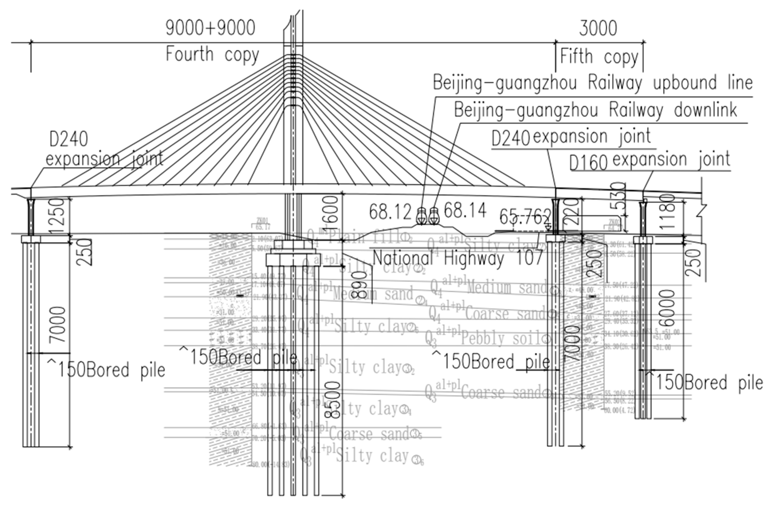
This study relies on the interchange project at the East Extension of Binhe South Road in Yuanshi County, Shijiazhuang, located in the northern part of the county’s main urban area, east of the County Labor Park. The bridge crosses the railway and highway using an overpass, connecting to National Highway 107 via a full interchange. The main bridge on Binhe South Road spans 480 m, with a span arrangement of [3 × 3 × 30 + (90 + 90) + 30] meters. The western half of the bridge, crossing the railway and highway, uses a (90 + 90) meter single-tower cable-stayed bridge with a width of 35.0 m. To reduce impact on the surrounding railways, a rotation method was used for construction (rotation weight: 21,200 tons, rotation angle: 79°). The bridge elevation layout is shown in
Figure 2.
4. Design of the Construction Monitoring Digital Twin System Based on SysML
4.1. Study of the V-Model Architecture of the System Based on RFLP Analysis Process
The MBSE approach for the digital twin system of the rotation construction monitoring follows the typical V-model development model [
22], which includes three major phases: lifecycle design, manufacturing, and operation and maintenance. The V-model architecture for the design and development of the digital twin system is shown in
Figure 3.
As shown in
Figure 3, the left part of the design phase is a top-down forward design and decomposition process. SysML is used to modularize and graphically represent the system’s requirements, functions, structure, and activities, achieving an organic integration of requirements, structure, and behavior. During the entire design decomposition phase, requirements analysis and validation are conducted starting from the investigation of stakeholders’ needs, determining the functions the system needs to include, and followed by analysis and testing. Use case diagrams are created to establish the connections between requirements and functions. Then, architecture analysis and design feasibility are verified from both logical and physical aspects. The right part is a bottom-up integration and verification process, divided into three parts: digital model validation, prototype model validation, and engineering application. The design decomposition phase is the focus in the study.
As can be seen from the V-model architecture, MBSE aims to drive the development process of the system through various models, and the complete model system runs through the whole life cycle of the system. Each link in the whole life cycle of the system is managed through a unified model, and the expression of product information is realized through the model, providing a unified data source and ensuring the traceability of data.
4.2. Requirement Analysis
The initial design concept or task for a system usually originates from requirements, which represent both stakeholder expectations of the system and the capabilities or conditions that the system needs to fulfil. The purpose of requirements analysis is to capture system stakeholder requirements, clearly define system design requirements and design constraints, and organize and manage the captured requirements in a structured, categorized and hierarchical manner. System requirements define stakeholder expectations and the capabilities a system must deliver. For the digital twin rotation monitoring system, the system architecture is directly shaped by these requirements, ensuring that the system addresses key challenges such as real-time risk prediction and multi-stakeholder coordination.
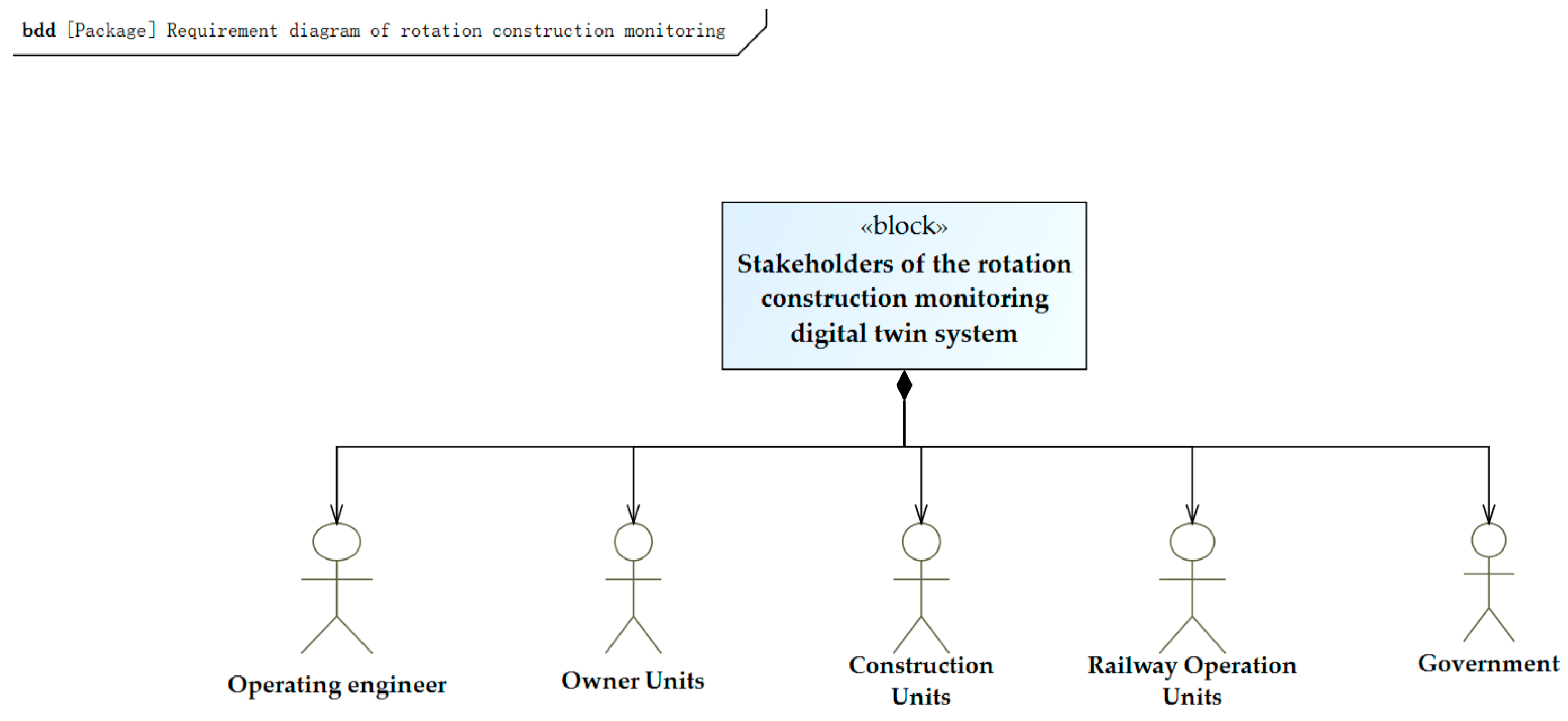
Firstly, the design task of this system should be clarified, the stakeholders (operating engineers, owner units, construction units, railway operation units, and the government) should be identified, and the system requirements should be modeled and analyzed through questionnaire surveys, market research, relevant policies and regulations, and other demand collection methods. The hierarchical structure of the system’s stakeholders is shown in
Figure 4. The requirements of different stakeholders may conflict, as seen in how railway operators prioritize minimal disruption to train schedules while construction teams aim to expedite rotation. The digital twin system resolves this by simulating “time windows” for rotation, balancing safety and efficiency.
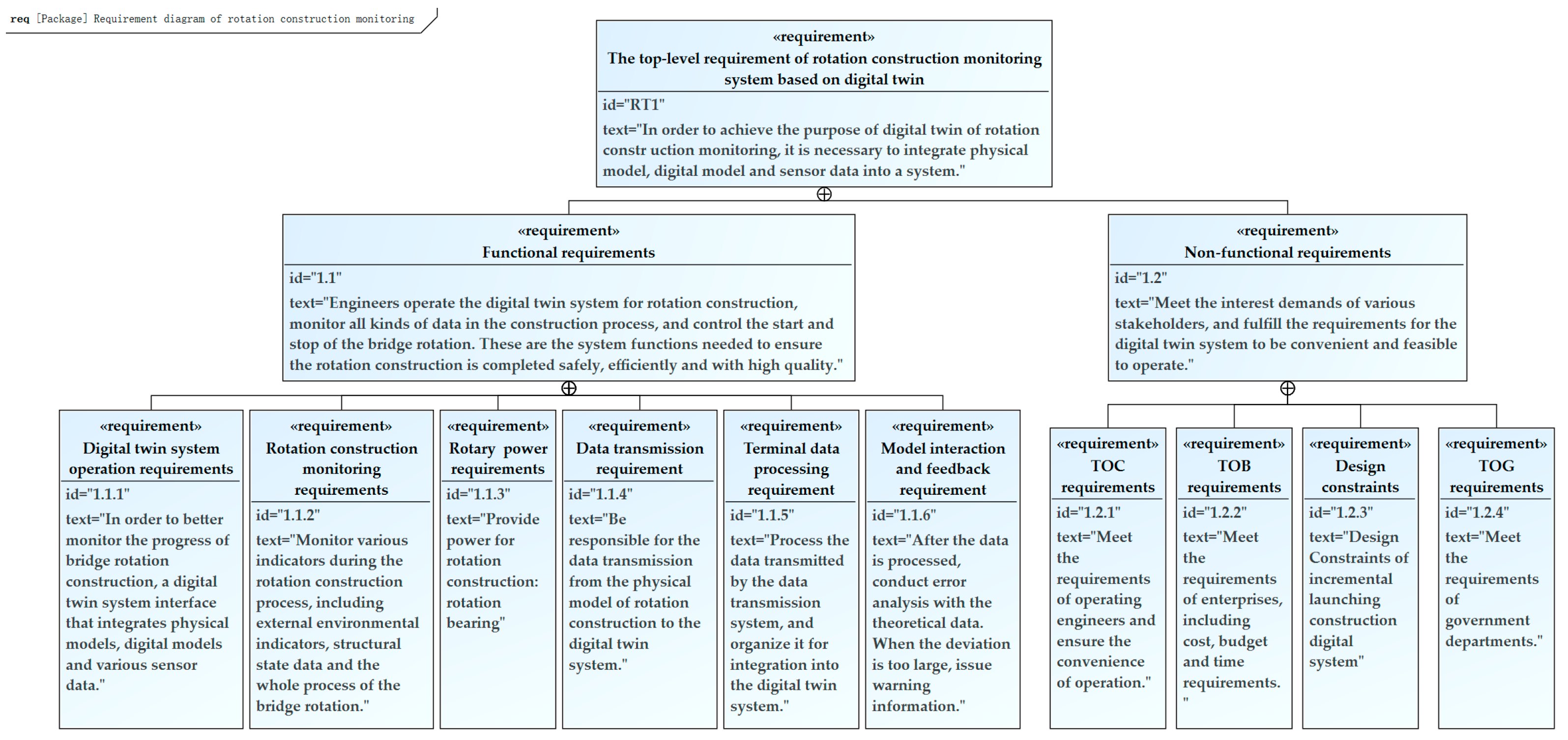
The top-level requirements of the digital twin-based cable-stayed bridge rotation construction monitoring system are categorized into functional and non-functional requirements, based on whether the requirements fulfill the corresponding functions, and with reference to relevant industry standards and technical specifications [
23]. The classification of the top-level requirements of the digital twin system is shown in
Table 1, and the top-level requirement diagram of the digital twin system is shown in
Figure 5. TOC requirements may limit the application of high-performance technologies across the digital twin system. In order for the entire system to be monitored quickly and accurately, real-time adjustment feedback requires high-performance hardware support, and this demand may exceed the customer’s budget requirements, so a requirements prioritization matrix can be established to identify key conflict points and make decisions.
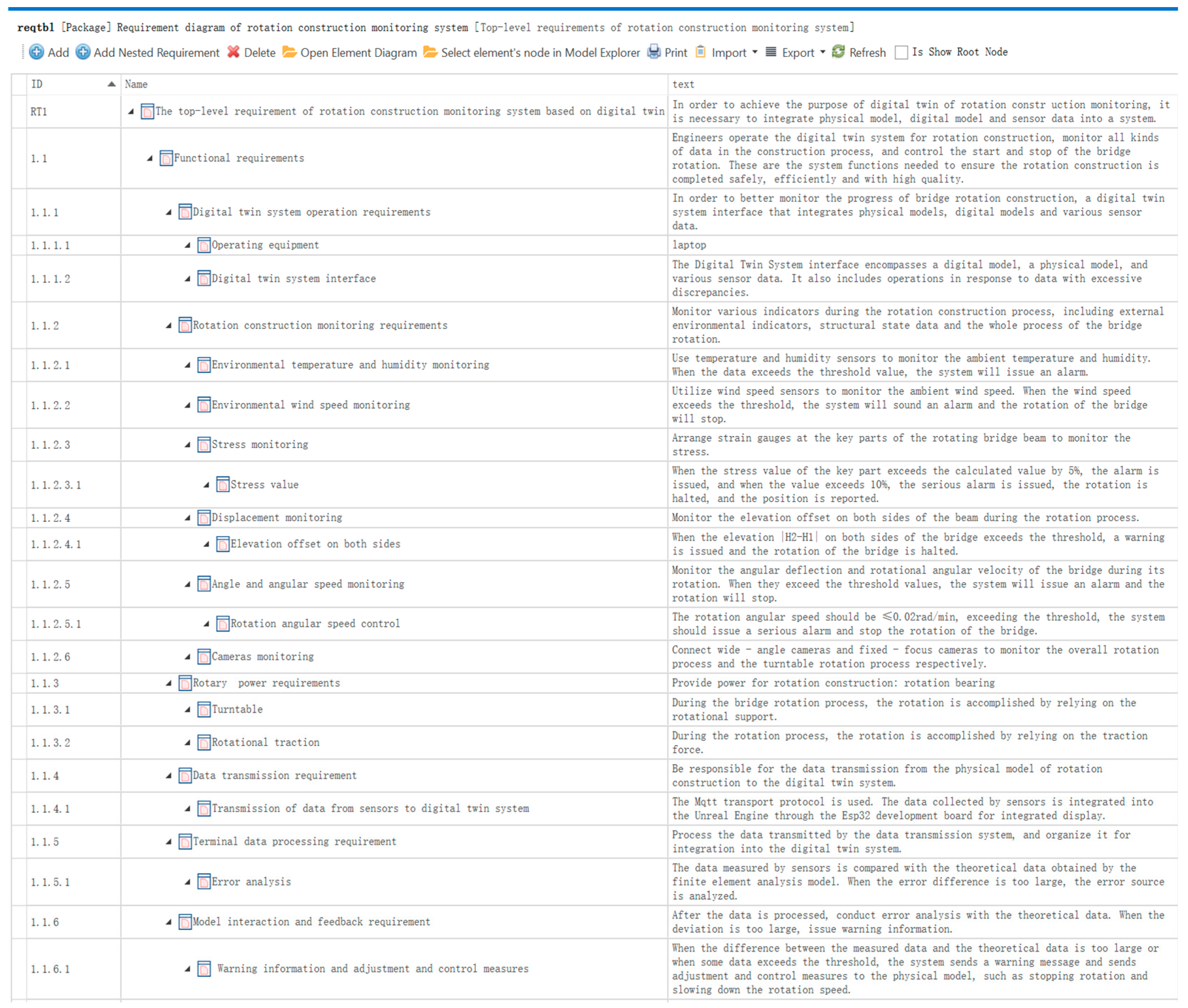
The requirement diagram is a key medium in SysML used to communicate and document system requirements in textual form. Requirement analysis modeling first involves itemizing the requirements from documents or tables, followed by creating a requirement model based on the itemized requirements. Functional requirements are crucial to system design, as they define the system functions needed to monitor the entire rotation construction process of the digital twin system, ensuring that the rotation is completed with high quality, efficiency, and safety. The functional requirement entries and requirement diagrams for the rotation construction monitoring digital twin system are shown in
Figure 6 and
Figure 7.
The requirement model not only outlines all the requirements that the monitoring system should fulfill, but also includes the relationships between these requirements, facilitating traceability and analysis. In the requirement diagram, connections with a cross-circle symbol represent the most basic type of relationship—the include relationship. In addition to this, there are six other types of requirement relationships: trace, derive, refine, satisfy, verify, and replication. In
Figure 7, besides the basic inclusion relationship, a refinement relationship is also used to provide further detailed descriptions of the requirements. For instance, in the case of the rotation construction monitoring requirements in
Figure 7, it includes six more specific requirements: monitoring of environmental temperature and humidity, wind speed, stress, displacement, angle and angular velocity, and camera monitoring of the entire rotation process. Among them, the angular velocity monitoring requirement is further elaborated: the rotation angular velocity should be ≤0.02 rad/min. If this threshold is exceeded, the system will issue a serious alarm and stop the bridge rotation.
As the system design progresses, various requirements may undergo changes. These changes can be directly updated in the requirement table, and the requirement diagram will also automatically generate the updated requirements.
4.3. Functional Analyses
Based on the requirement analysis, a functional model of the system is established and a functional analysis is performed. According to the requirements and metrics obtained during the requirements analysis phase, use case diagrams [
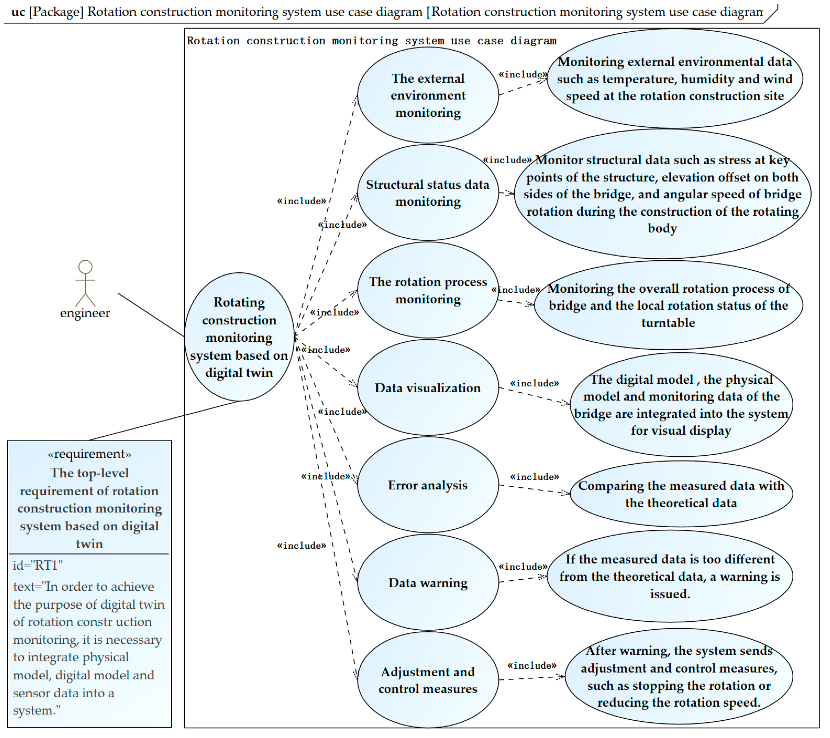
24] are employed to further refine the stakeholders’ needs and analyze the system’s functional scenarios. In SysML, the functionality or service provided by the system is referred to as “use cases,” represented by ellipses, while the relationship between the “actor” and the “use case” is termed the “communication path.” Use case diagrams describe the interactions between system use cases and their participants, thereby expressing system functionality, reflecting the interaction between the actor and the use case, and illustrating the interaction between the actor and the system. The use case diagram of the rotation construction monitoring system is shown in
Figure 8.
In
Figure 8, the functions of the rotation construction monitoring system include monitoring the external environment, monitoring structural status data, monitoring the entire bridge rotation process, visualizing data, error analysis, data warning, and adjusting control measures. The term “include” refers to the include relationship, indicating that the execution of the parent use case requires the execution of its child use cases. For example, the data visualization function involves integrating the bridge’s digital model, physical entity model, and monitoring data into the system for visualization. The data warning function involves issuing a warning when the deviation between the measured displacement, angular velocity, etc. on both sides of the bridge and the theoretical data exceeds a specified threshold.
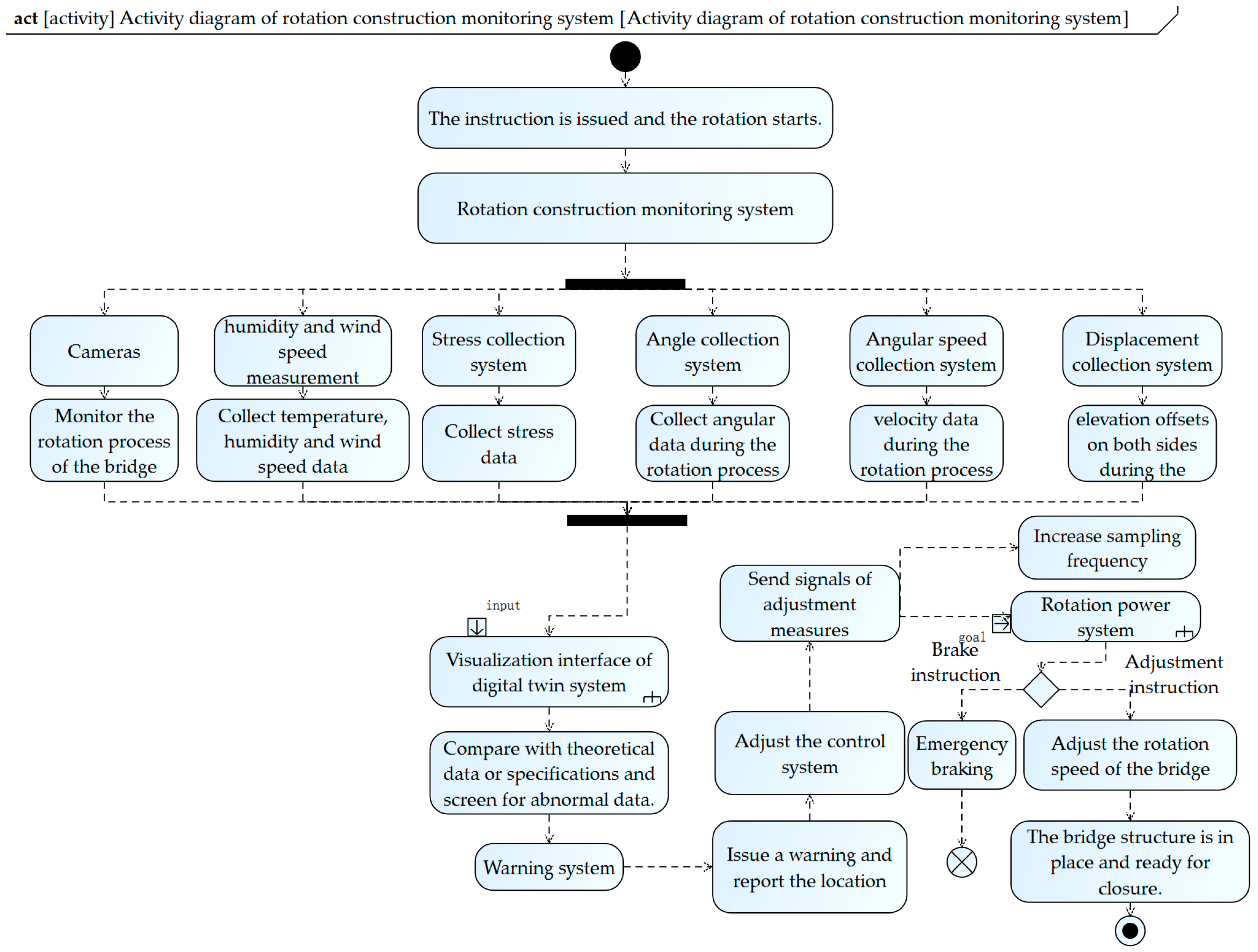
After completing the use case modeling of the system and clarifying the functions that the rotation construction monitoring system needs to implement, the next step is to understand the logical relationships between the functions and design the logic for implementing those functions. Functional and logical design is the organization of the process for achieving system functions and does not involve the system’s structure. Therefore, activity diagrams are chosen to design the system’s functionality. The diagram for the rotation construction monitoring system is shown in
Figure 9.
The activity diagram describes the process of the rotation construction monitoring system. The bridge receives a command before rotation begins, and the monitoring system activates simultaneously as the bridge starts to rotate. The on-site camera equipment monitors both the overall rotation process of the bridge and the local rotation process of the turntable, whereas temperature, humidity, and wind speed measurement systems collect temperature, humidity, and wind speed data, respectively. The stress measurement system gathers stress data, and the angle and angular velocity measurement systems collect the angle and angular velocity data throughout the rotation process. Additionally, the displacement measurement system tracks the elevation offset on both sides of the bridge during rotation. The collected data is input into the digital twin system for visualization, producing visuals such as real-time monitoring displays and changes in various data curves. The measured data is compared with theoretical data or relevant standards to identify anomalies. Abnormal data is sent to the early warning system, which triggers alerts and reports abnormal positions to the adjustment control system. The adjustment control system then sends corresponding signals to the sensor system and the rotation power system to increase the sampling frequency, implement braking, or adjust speed, ensuring emergency stops or necessary speed modifications for the bridge.
4.4. Architecture Analysis and Synthesis
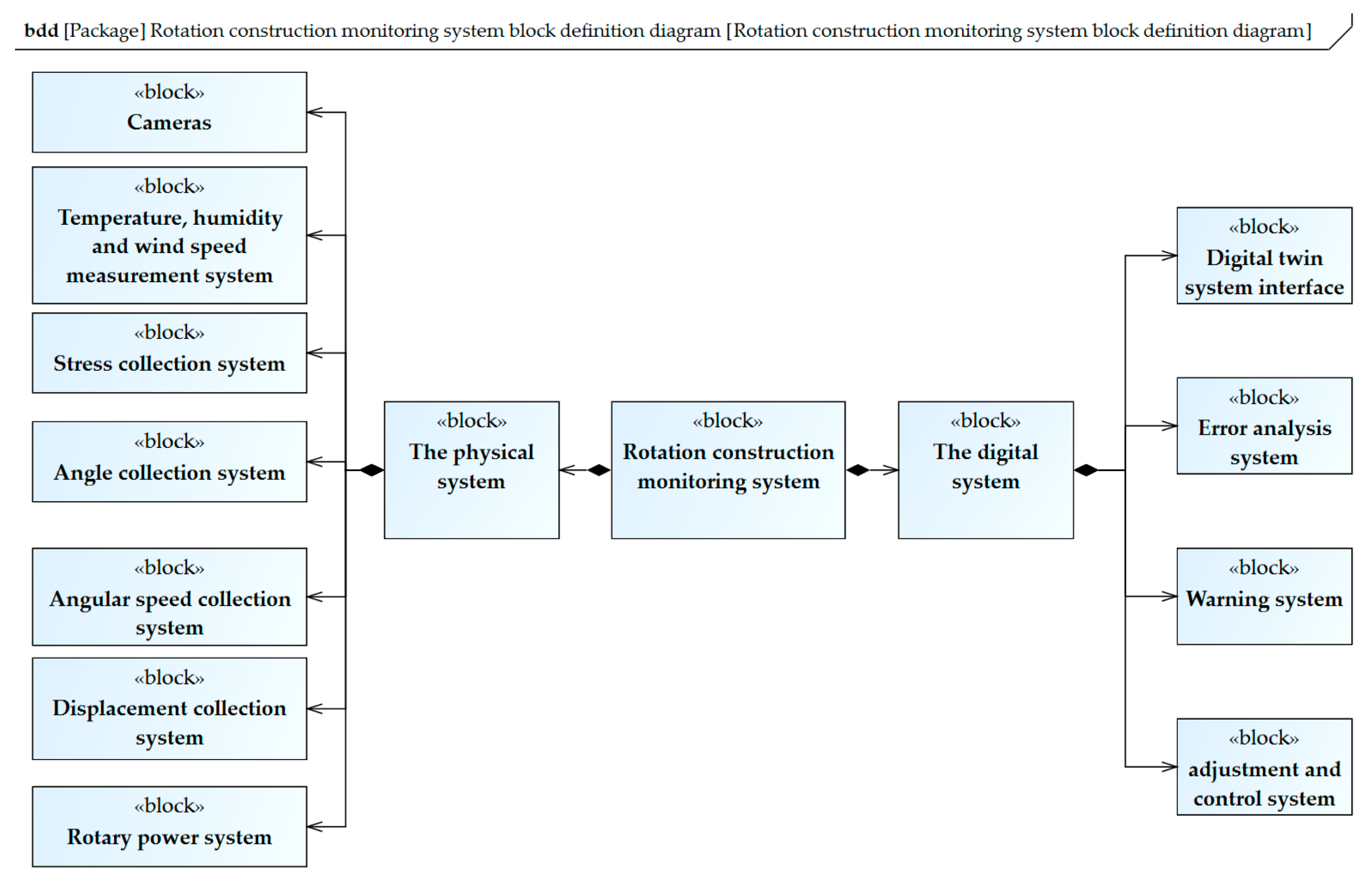
Functional analysis identifies system behavior, while architecture analysis builds physical components, interfaces for information and material interaction between components, etc. that can implement system behavior based on the results of requirements and functional analysis. Modules are the core elements in SysML, typically encompassing values, services, behaviors, constraints, and relationships with other such elements. A Block Definition Diagram (BDD) in SysML defines both the logical and physical structures of the system, providing an intuitive representation of blocks, features, and the relationships between them. Based on the system’s functional use case diagram, requirement diagram, and construction monitoring content, BDD is used to construct the physical and digital architecture model of the rotation construction monitoring system. This model illustrates the physical and digital information required to implement the system. The system architecture model is shown in
Figure 10. BDD is divided into three levels, and different levels are connected by the Combined Association, which indicates the subordinate relationship between Modules. The rotation construction monitoring system is divided into two parts, the physical end and the digital system, where the physical end is divided into the on-site camera equipment group, the temperature, humidity, and wind speed measurement system, the stress acquisition system, the angle acquisition system, the angular velocity acquisition system, the displacement acquisition system, and the rotation drive system and the digital end is divided into the digital twin system interface, the error analysis system, the early warning system, and the adjustment control system.
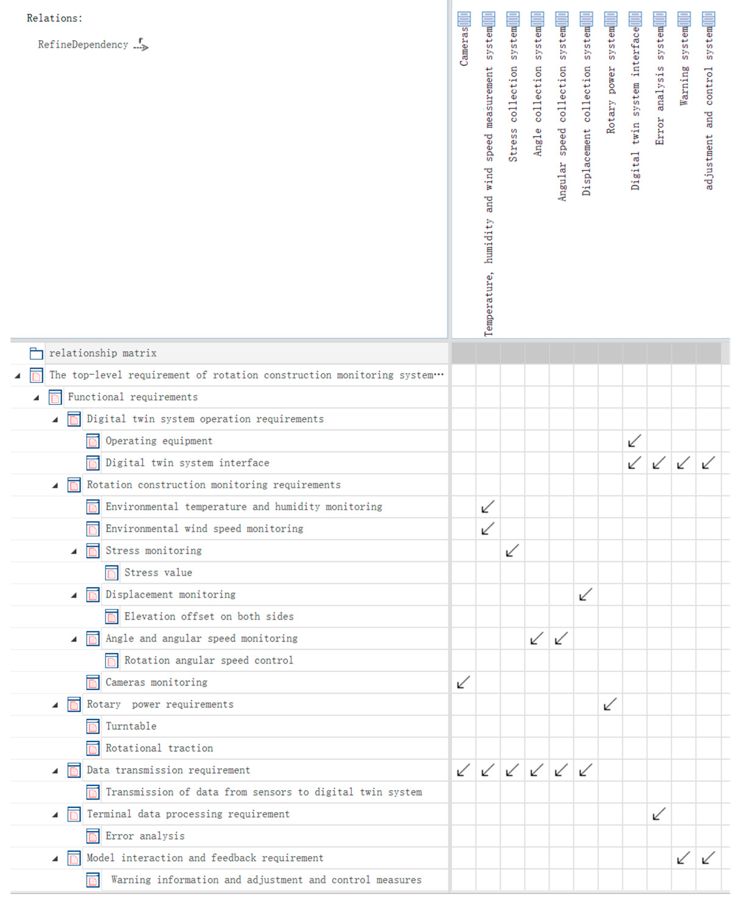
Thus, based on the requirement, functional, and architecture analyses, the relationships between requirements and other design elements were established, ensuring traceability [
25]. A two-dimensional requirements traceability matrix is typically used in modeling software, with rows and columns representing traceable elements, which may be of the same or different types and reflect one-to-many or many-to-one relationships. By tracing, satisfy and refine relationships between requirements and modules to ensure that each requirement corresponds to specific functional modules and physical implementations, this closed-loop management reduces design omissions or conflicts. The requirements improvement relationship matrix is shown in
Figure 11.
From the requirement improvement relationship matrix, it can be seen that each requirement of the system can be satisfied by the corresponding module in the system architecture. For example, the data transmission demand can be satisfied by the on-site camera equipment group, the temperature, humidity, and wind speed measurement system, the stress acquisition system, the angle acquisition system, the angular velocity acquisition system, and the displacement acquisition system; the terminal data processing demand can be satisfied by the error analysis system; and the model interaction feedback demand can be satisfied by the early warning system and the adjustment control system. The consistency of system design and system requirements can be clarified through this traceability matrix, which ensures that each system requirement can be satisfied by the corresponding physical architecture. For example, when the requirement changes (for example, the angular velocity threshold is adjusted to 0.015 rad /min), the associated module (angular velocity acquisition system) is directly marked through the traceability relationship to prompt synchronous update.
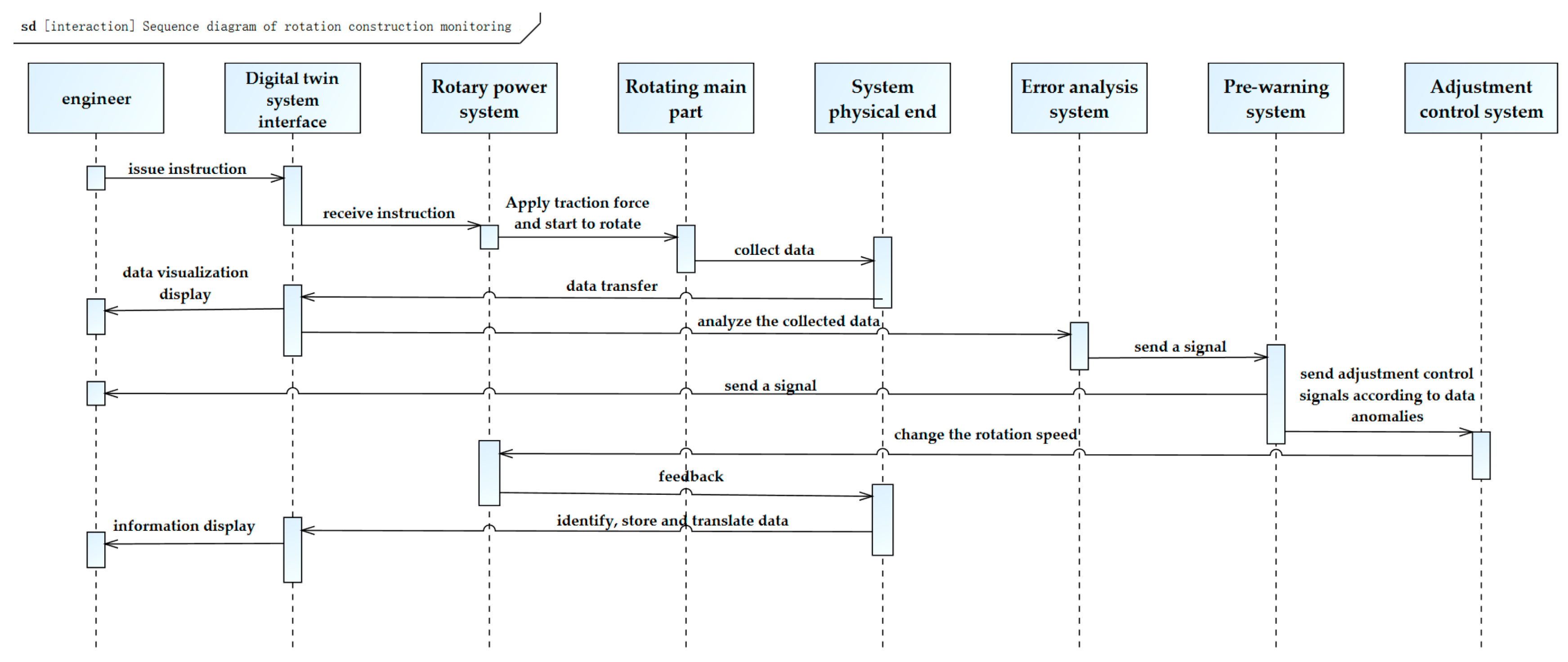
In addition, in the architecture design, sequence diagrams can be used to describe the flow interactions and linkage relationships between activity performers and related subsystems and modules, as well as the interactions between module components within the system, so that sequence diagrams can be used to further refine the activities of the rotation construction monitoring system. The system sequence diagram is shown in
Figure 12.
4.5. The Verification of Digital Twin Systems
After requirement analysis, functional analysis, architecture analysis, and synthesis, the subsequent verification of the digital twin system is carried out. Since the bridge in the engineering information is still under construction and the bridge rotation has not yet started, this study selects a 1:100 scale bridge pilot model as the physical model in the digital twin system for validation. The scaled-down bridge has a span of 90 cm + 90 cm and a width of 35 cm, forming the basis for constructing the digital twin system. The entire bridge rotation construction monitoring digital twin system consists of two parts: the physical end and the digital end. The physical system mainly includes three components: the bridge rotating main body model (scale model), monitoring sensors, and the swivel power device. As for the selection of monitoring sensors, there are many emerging sensors that can be used in the construction monitoring of cable-stayed bridges (fiber grating sensors, elasto-magnetic sensors, liDAR, etc.). In this paper, the digital twin system adopts a scaled model for model verification. Therefore, a DHT11 temperature and humidity sensor, MPU6050 angle module, wind speed and direction meter, and laser displacement meter are used to monitor the structural state [
26,
27,
28,
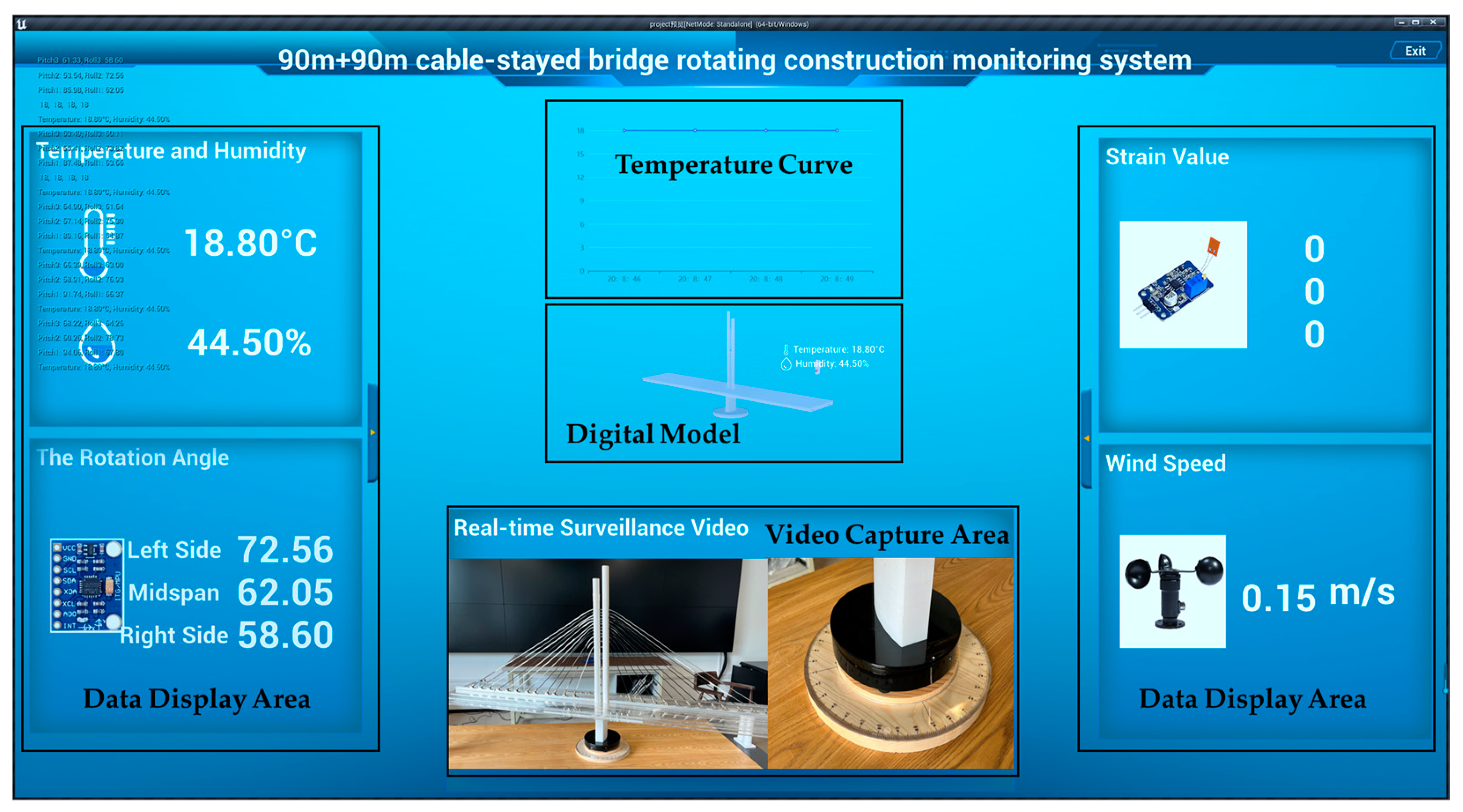
29]. The digital system primarily contains the bridge’s digital model and the interface of the digital twin system. The system is integrated using Unreal Engine 4.27. The digital model is created with Rhino 7, and FBX format files exported from Rhino can be directly imported into UE for editing. Various sensors are connected through the Esp32 WROOM-32 development board module, with data collected and uploaded to Arduino. Meanwhile, Esp32 and MQTT operate under the same WiFi network, enabling MQTT to receive messages from Esp32, transmit data in real time to the MQTT server, and send MQTT messages to UE via the MQTT plugin in UE. The sensor data is used as the measured data in the digital twin system, and the data in the finite element analysis model of the bridge is used as the theoretical data. This achieves data transmission, compares measured data with theoretical data, and triggers system alerts and adjustment control measures (including braking) when errors exceed thresholds. When the sensor of the system fails, the real risk may not be detected, which may cause bridge damage and affect the construction progress. To counter this, all sensors should be added for dual-channel monitoring. The final integrated system interface is shown in
Figure 13. In future practical engineering applications, bridge finite element analysis (FEA) models can be analyzed under diverse load conditions. The resulting data can then be processed using neural network algorithms to identify hazardous load scenarios, thereby enabling predictive maintenance [
30].
The research focus of this paper is on a rotating construction monitoring digital twin system based on a cable-stayed bridge. However, whether it is the method for designing a digital twin system through MBSE or the final design of the system itself, the approach can be extended to the construction of other bridge types (e.g., suspension bridges, arch bridges) or non-bridge intelligent facilities. The MBSE-driven V-model architecture (RFLP framework) presented in this paper is modular in nature; due to this modularity, the system can be adapted to tunnels or buildings by reconfiguring requirements and functional models. The digital twin system designed in this paper integrates the physical and digital layers and can adapt to different construction scenarios by configuring various sensors and simulation models.
5. Conclusions
Design research on the digital twin system for monitoring rotation construction has been conducted based on MBSE system engineering. The V-model architecture of the digital twin system has been proposed, based on the requirements-functional-logical-physical (RFLP) process. SysML has been used for further requirement, function, architecture, and integration analyses of the system. The design decomposition phase has been completed, providing a foundation for the subsequent model validation phase. The main results obtained can be summarized as follows:
(1) The bridge rotation construction method does not have the complex system architecture seen in fields such as aerospace, defense, or weapons. However, the digital twin system for monitoring bridge rotation construction requires the integration of both physical and digital components within the same system to enable data transmission and interaction. Based on these characteristics, the architecture of the digital twin system has been designed by MBSE. The results have shown that the MBSE approach has improved design efficiency (e.g., enabling proactive conflict resolution among stakeholders through scenario planning and allowing rapid integration of new requirements via MBSE’s traceability features), making the entire system more intuitive, clear, standardized, and visually represented to all stakeholders.
(2) Based on the RFLP analysis process, a V-model architecture of the digital twin system for monitoring the rotation construction has been built. The entire lifecycle of the rotation construction monitoring system has been decomposed into four stages: design decomposition, digital model validation, prototype model validation, and engineering application. This method has been applied not only in the bridge construction stage but also in the bridge health monitoring stage.
(3) Based on the top-down forward design and decomposition process in the design decomposition phase, the requirement analysis, functional analysis, architecture analysis, and synthesis of the digital twin system have been conducted using SysML. The bridge rotation construction digital twin system is complex and requires interaction between the digital and physical components to enable data and information exchange. When new requirements or functions need to be added, they can be directly incorporated into the MBSE with each requirement and the function is traceable to the origin, allowing for easy modification or addition.
(4) According to the research presented in this paper, the application of the MBSE methodology demonstrates feasibility in designing digital twin systems for rotating construction monitoring of bridges. However, despite its feasibility, several practical limitations persist, including implementation costs, resource allocation requirements, system complexity, and applicability constraints. Furthermore, the methodology’s capabilities in model-driven collaborative design and risk prediction surpass those of conventional approaches. Future research should focus on maximizing MBSE’s value through three strategic dimensions: developing standardization frameworks, integrating systematic toolchains, and implementing phased strategies to ensure operational efficacy.
(5) In future research, MBSE could be applied not only to bridge engineering but also extended to interdisciplinary domains. For instance, machine learning techniques could be explored to enable long-term deformation analysis, thereby extending digital twin capabilities to predictive maintenance phases for bridge infrastructures. In smart city development, for example, MBSE could facilitate multi-domain system integration by unifying models of transportation networks, energy grids, and building ecosystems, enhancing disaster emergency response frameworks and urban resource optimization strategies. In tunnel engineering, MBSE could optimize tunnel boring parameters and mitigate construction risks through systematic integration of geological survey datasets, real-time shield machine operational analytics, and ground settlement prediction models. These cross-disciplinary applications highlight MBSE’s capacity to advance lifecycle management and risk mitigation in complex civil engineering systems.
Author Contributions
Conceptualization, Y.Z. (Yuhan Zhang) and W.H.; methodology, Y.Z. (Yuhan Zhang); software, Y.Z. (Yuhan Zhang) and Y.L.; validation, Y.Z. (Yuhan Zhang), Y.Z. (Yimeng Zhao), W.H. and Y.L.; formal analysis, Y.Z. (Yuhan Zhang) and Y.Z. (Yimeng Zhao); investigation, Y.Z. (Yuhan Zhang) and Z.L.; resources, Y.Z. (Yuhan Zhang) and Z.L.; data curation, Y.Z. (Yuhan Zhang) and Y.Z. (Yimeng Zhao); writing—original draft preparation, Y.Z. (Yuhan Zhang) and Y.Z. (Yimeng Zhao); writing—review and editing, Z.L. and W.H.; visualization, Y.Z. (Yuhan Zhang); supervision, Z.L. and W.H.; project administration, W.H. and Y.L.; funding acquisition, Y.L. All authors have read and agreed to the published version of the manuscript.
Funding
This research was funded by the Hunan Provincial Department of Transportation Science and Technology Progress and Innovation Project, grant number 202217.
Data Availability Statement
The original contributions presented in this study are included in the article. Further inquiries can be directed to the corresponding author.
Conflicts of Interest
Author Yi Liu was employed by the Hunan Zhi Li Science and Technology Co., Ltd. The remaining authors declare that the research was conducted in the absence of any commercial or financial relationships that could be construed as potential conflicts of interest.
References
- Grieves, M.; Vickers, J. Digital twin: Mitigating unpredictable, undesirable emergent behavior in complex systems. In Transdisciplinary Perspectives on Complex Systems: New Findings and Approaches; Springer: Cham, Switzerland, 2017; pp. 85–113. [Google Scholar]
- Shafto, M.; Conroy, M.; Doyle, R.; Glaessgen, E.; Kemp, C.; LeMoigne, J.; Wang, L. Draft, Modeling, Simulation, Information Technology & Processing Roadmap; National Aeronautics and Space Administration: Washington, DC, USA, 2012; Volume 32, pp. 1–38. [Google Scholar]
- Shim, C.S.; Kang, H.R.; Dang, N.S. Digital twin models for maintenance of cable-supported bridges. In Proceedings of the 2nd International Conference on Smart Infrastructure and Construction: Driving Data-Informed Decision-Making, ICSIC 2019, Cambridge, UK, 1–3 July 2019; pp. 737–742. [Google Scholar]
- Shim, C.S.; Dang, N.S.; Lon, S.; Jeon, C.H. Development of a bridge maintenance system for prestressed concrete bridges using 3D digital twin model. Struct. Infrastruct. Eng. 2019, 15, 1319–1332. [Google Scholar] [CrossRef]
- Yu, G.; Zhang, S.; Hu, M.; Wang, Y.K. Prediction of Highway Tunnel Pavement Performance Based on Digital Twin and Multiple Time Series Stacking. Adv. Civ. Eng. 2020, 2020, 8824135. [Google Scholar] [CrossRef]
- Friedenthal, S.; Griego, R.; Sampson, M. INCOSE Model Based Systems Engineering (MBSE) Initiative. In Proceedings of the INCOSE 2007 Symposium, San Diego, CA, USA, 24–29 June 2007. [Google Scholar]
- He, X.; Zhang, H.; Ding, G.; Li, R.; Wang, S. Modeling Method for Design of High-speed Train Bogie System Based on MBSE. Mach. Des. Res. 2022, 38, 179–186. (In Chinese) [Google Scholar]
- Gao, S.; Cao, W.; Fan, L.H.; Liu, J.H. MBSE for Satellite Communication System Architecting. IEEE Access 2019, 7, 164051–164067. [Google Scholar] [CrossRef]
- Corrado, J.K. Model-based systems engineering adoption in the US Nuclear industry. Nucl. Eng. Des. 2025, 432, 113752. [Google Scholar] [CrossRef]
- Yang, H.G.; Xia, Z.; Chen, Y.Q.; Zhu, L.Q.; Dai, L.H.; Xu, R.T.; Sun, G.Y.; Yu, H.Y.; Xu, W.T. Research on visual simulation for complex weapon equipment interoperability based on MBSE. Multimed. Tools Appl. 2024, 83, 13463–13482. [Google Scholar] [CrossRef]
- Zhang, X.; Wu, B.; Zhang, X.; Duan, J.; Wan, C.H.; Hu, Y.M. An effective MBSE approach for constructing industrial robot digital twin system. Robot. Comput.-Integr. Manuf. 2023, 80, 102455. [Google Scholar] [CrossRef]
- Keskin, B.; Salman, B.; Koseoglu, O. Architecting a BIM-Based Digital Twin Platform for Airport Asset Management: A Model-Based System Engineering with SysML Approach. J. Constr. Eng. Manag. 2022, 148, 04022020. [Google Scholar] [CrossRef]
- Keskin, B.; Salman, B. Building Information Modeling Implementation Framework for Smart Airport Life Cycle Management. Transp. Res. Rec. 2020, 2674, 98–112. [Google Scholar] [CrossRef]
- Hu, M.Y.; Zhang, X.Y.; Peng, C.T.; Zhang, Y.X.; Yang, J. Current status of digital twin architecture and application in nuclear energy field. Ann. Nucl. Energy 2024, 202, 110491. [Google Scholar] [CrossRef]
- Yang, X.L.; Liu, X.M.; Zhang, H.; Fu, L.; Yu, Y.B. Meta-model-based shop-floor digital twin architecture, modeling and application. Robot. Comput.-Integr. Manuf. 2023, 84, 102595. [Google Scholar] [CrossRef]
- Xia, T. Design of Civil Airplane Condition Monitoring System Based on MBSE. Master’s Thesis, University of Electronic Science and Technology, Chengdu, China, 2021. (In Chinese). [Google Scholar]
- Yu, X.; Mou, R. System modeling and risk analysis of the Sichuan–Tibet Railway project. J. Transp. Eng. Part A Syst. 2021, 147, 04021094. [Google Scholar] [CrossRef]
- De Saqui-Sannes, P.; Vingerhoeds, R.A.; Garion, C.; Thirioux, X. A Taxonomy of MBSE Approaches by Languages, Tools and Methods. IEEE Access 2022, 10, 120936–120950. [Google Scholar] [CrossRef]
- Delligatti, L. SysML Distilled: A Brief Guide to the Systems Modeling Language; Addison-Wesley: Boston, MA, USA, 2013. [Google Scholar]
- Hallqvist, J.; Larsson, J. Introducing MBSE by using systems engineering principles. In Proceedings of the INCOSE International Symposium, Orlando, FL, USA, 10–13 July 2006; pp. 512–525. [Google Scholar] [CrossRef]
- Gregory, J.; Berthoud, L.; Tryfonas, T.; Rossignol, A.; Faure, L. The long and winding road: MBSE adoption for functional avionics of spacecraft. J. Syst. Softw. 2020, 160, 110453. [Google Scholar] [CrossRef]
- Yang, Y. Incremental Launching Construction Analysis and Digital Construction Research on UHPC Continuous Beams. Master’s Thesis, Southwest Jiaotong University, Chengdu, China, 2023. (In Chinese). [Google Scholar]
- Lyu, W.; Yang, Y.C.; Miao, J.G.; Cao, S.H.; Kong, L.S. Architecture Preliminary Design and Trade-Off Optimization of Stratospheric Airship Based on MBSE. Aerospace 2024, 11, 582. [Google Scholar] [CrossRef]
- Douglass, B.P. Agile Systems Engineering; Morgan Kaufmann: Burlington, MA, USA, 2015. [Google Scholar] [CrossRef]
- Liu, J.; Liu, J.H.; Zhuang, C.B.; Liu, Z.W.; Miao, T. Construction method of shop-floor digital twin based on MBSE. J. Manuf. Syst. 2021, 60, 93–118. [Google Scholar] [CrossRef]
- Chen, S.; Ma, Y.; Su, H.; Fan, X.; Liu, Y. Few-Mode Fiber-Based Long-Period Fiber Gratings: A Review. J. Opt. Photonics Res. 2024, 1, 2–15. [Google Scholar] [CrossRef]
- Cappello, C.; Zonta, D.; Laasri, H.A.; Glisic, B.; Wang, M. Calibration of Elasto-Magnetic Sensors on In-Service Cable-Stayed Bridges for Stress Monitoring. Sensors 2018, 18, 466. [Google Scholar] [CrossRef]
- Khan, R.Y.M.; Ullah, R.; Faisal, M. High-Temperature Sensing with Iron-Ceramic Enhanced Fiber Bragg Grating Sensors: Encapsulation Strategies and Concentration Dependencies. J. Opt. Photonics Res. 2024. [Google Scholar] [CrossRef]
- Li, X.; Hu, Y.; Jie, Y.; Zhao, C.; Zhang, Z. Dual-Frequency Lidar for Compressed Sensing 3D Imaging Based on All-Phase Fast Fourier Transform. J. Opt. Photonics Res. 2023, 1, 74–81. [Google Scholar] [CrossRef]
- Wang, S.; Lin, S.; Yang, R.L. A lightweight convolutional neural network for multipoint displacement measurements on bridge structures. Nonlinear Dyn. 2024, 112, 11745–11763. [Google Scholar] [CrossRef]
| Disclaimer/Publisher’s Note: The statements, opinions and data contained in all publications are solely those of the individual author(s) and contributor(s) and not of MDPI and/or the editor(s). MDPI and/or the editor(s) disclaim responsibility for any injury to people or property resulting from any ideas, methods, instructions or products referred to in the content. |
© 2025 by the authors. Licensee MDPI, Basel, Switzerland. This article is an open access article distributed under the terms and conditions of the Creative Commons Attribution (CC BY) license (https://creativecommons.org/licenses/by/4.0/).


