1. Introduction
Over the past decade, the construction industry has experienced many challenges, induced by economic fluctuations, supply shortages, or global political events. Additionally, the construction industry has been identified as a primary contributor to climate change and must therefore adapt to new standards and societal expectations [
1,
2,
3,
4,
5,
6,
7]. In response, architects, engineers, and contractors have to adjust to the quickly changing conditions. As a result of the named challenges, construction firms as well as academic institutions have started to investigate the use of additive manufacturing (AM) in construction as a methodology to automate construction processes, addressing the shortage of labour, decreasing the use of materials, and increasing the efficiency of construction components, thereby contributing to the sector’s journey towards sustainability [
8,
9,
10,
11,
12,
13]. Additionally, current research—in particular, lifecycle analyses—is used to analyse and quantify these advantages of AM in comparison to traditional construction methods [
14,
15,
16,
17,
18].
To explore the extended applicability of AM processes, a student design challenge was conducted to create innovative structures focusing on AM techniques researched at TU Braunschweig (TUBS) and TU Munich (TUM) within the collaborative research centre TRR 277 AMC [
19]. In this context, a five-storey building was designed, leveraging the geometric freedom provided by Shotcrete 3D Printing (SC3DP). The architectural design underwent iterative discussions, and during the progression from computational design to manufacturing, the concept was translated into a digital twin model. This holistic approach, integrating digital methods and processes, enabled the realisation of a section of the designed building at a 1:1 scale. This structure consists of three elements: a wall, a column, and a ceiling element. The wall element is printed as a monolithic load-bearing element and is reinforced by short rebar insertion (SRI) and interlayer reinforcement (ILR). The column is printed as a hollow structure reinforced by SRI and robotic fibre winding (RFW). Functions such as ducts or plugs are integrated into both elements, while additionally a cover layer of concrete and surface finishing were applied to achieve high-quality architectural concrete surfaces. The ceiling element consists of a steel frame and an RFW structure to showcase the geometric possibilities of this reinforcement process.
Figure 1 shows the elements and their arrangement as an assembled standalone structure.
Furthermore, this study emphasises the critical role of a comprehensive digital workflow in fully leveraging the potential of AM and digital fabrication with concrete (DFC). By employing digital tools throughout the entire process—from the initial design phase to post-manufacturing activities such as inspecting dimensional stability, quality control, and monitoring—this study showcases the strength of digital tools as an interconnected ecosystem. Consequently, a conceptual workflow is introduced, detailing the various steps involved, primarily focusing on design, manufacturing, and assembly from digital to real.
2. State of the Art
This section elaborates on the current developments of AM and DFC in construction. Moreover, the utilised AM technique for this study is introduced along with the digital methods for quality control and visualisation of additional functions and features within the structure.
2.1. Digital Fabrication with Concrete
While small-scale research on the material–process interaction or material properties is essential to fundamentally understand the intricacies of AM processes, there is a need for large-scale investigations and demonstrators in order to validate this research in the context of construction fabrication. Currently, concrete extrusion is the most commonly applied AM technique for large-scale application. Companies such as ICON, Peri, Rupp Gebäudedruck, CyBE, XtreeE, or WinSun utilise the layered approach to rapidly print furniture, small bridges, family houses, or up to two-storey structures [
20,
21,
22,
23,
24,
25,
26]. Most printed structures are used as a formwork to integrate a reinforcement cage and cast concrete inside the printed shell. In this case, the printed elements act as a lost formwork and an aesthetic facade for the building [
27,
28,
29,
30]. Furthermore, these cavities can be filled with insulation to increase the thermal performance of the walls. While these examples already demonstrate the high applicability of the AM process, they also show challenges [
31,
32]. These challenges range from ensuring compatibility between the design intent and the manufacturing capabilities to dealing with the structural analysis, approval processes, and integrating reinforcement within the structures. Therefore, simple structural solutions are usually selected, to obtain a standard building permit; e.g., concrete standard Eurocode 2 can be utilised for validation on a material level (durability, resistance of wall anchors), while the similarity to masonry structures can be used for verification on a structural level (Eurocode 6) [
33]. More advanced approaches utilise 3D concrete extrusion for force-flow-oriented printing to increase the efficiency and decrease the material usage of an element [
34,
35,
36,
37,
38]. However, this approach can mostly be adapted in the fabrication of horizontal elements.
Nevertheless, the industry is also in need of comprehensive economic analyses for a market implementation. Empirical data on cost, productivity, and value are essential for contractors and applicators of DFC. Performing comprehensive economic evaluations will not only provide evidence of the practical benefits but also support its wider adoption and integration into conventional construction workflows [
6,
39,
40].
The challenges occurring with 3D concrete printing collectively affect the efficiency, reliability, and scalability of AM methods in the construction industry. Addressing these challenges requires large efforts regarding technological development, regulatory adaptation, and professional education. In summary, despite the advancements, a clear research gap remains regarding AM large-scale application in construction and performance assessment. Even though projects have been realised and lab studies performed on the application process, the practical advantages of AM processes in real-world construction scenarios remain insufficiently explored. This gap is particularly evident in the case of SC3DP, where experimental validation at the architectural or structural scale is still scarce. Accordingly, there is pressing need to demonstrate the applicability and robustness of SC3DP in large-scale use cases, while accounting for the integrated digital workflow that spans from digital design to fabrication and post-processing.
2.2. Shotcrete 3D Printing
The research on AMC started in 2015 with the development of a technique combining traditional shotcrete and 3D printing [
41,
42]. This research led to SC3DP, which can be used for different applications within DFC [
43,
44,
45], e.g., to 3D print reinforced construction elements with comparably high surface quality. To focus on the development of this technique and to enable large-scale manufacturing, in 2016, the Digital Building Fabrication Laboratory (DBFL) was established at TUBS [
46,
47]. The DBFL uniquely combines two fundamentally different manufacturing units within one setup: a CNC-controlled five-axis gantry mill and a six-axis heavy-duty robot, mounted on a separate three-axis gantry. The integration of robotic control into the CNC environment allows the DBFL to operate both the CNC and robot portal either separately or in a collaborative manner. The facility focuses on additive manufacturing, especially with mineral-based materials, and subtractive post-processing techniques such as milling, grinding, and smoothing [
48,
49]. The available workspace measures approximately 16 m × 8 m × 2.5 m, enabling the production of large-scale architectural components.
SC3DP, which is based on the automated jetting of a wet-mix concrete, was selected as the AM method for the production of the presented structure. SC3DP employs the following digitally controlled parameters: concrete volume flow (
con), air volume flow (
air), accelerator dosage (dos
acc), nozzle distance (d
nozzle), traverse velocity (ν), and the spray angle (α) (see
Figure 2). The material is pumped to the nozzle at a defined concrete volume flow. At the nozzle, it is sprayed with high kinetic energy through pressurised air at a defined nozzle distance. In addition, the traverse speed of the nozzle can be adjusted. Combined with variations in the outlet diameter of the nozzle (d
o), the spray jet speed and thus the resulting strand geometry can be influenced. When jetting the material, the nozzle angle α can be controlled as part of the path planning for angled material application. This allows a high degree of geometric freedom and enables the lateral application of covering layers for surface finishing or the printing of horizontal consoles.
Despite the high geometric degree of freedom of the SC3DP process, certain limitations arise as a result of the employed materials, the machine setup, and moreover the process itself. Through the jetting of material, the strand width generally ranges from 5 cm to 30 cm [
51,
52]. This depends on the nozzle geometry as well as the parameters used during the process. In general, the print resolution of the SC3DP process is lower than in extrusion-based processes due to the application method and the defined minimum nozzle opening. Furthermore, the planning differs from conventional extrusion processes, especially for printing overhangs and corbels. A standard approach such as in plastic 3D printing is to have layers overlap stepwise to create overhangs, but this is only possible to an extent due to the kinetic energy used during material application [
53]. The geometric freedom of six-degree-of-freedom (DoF) robot-based material jetting allows for a tilted application, which is aligned with the target geometry. This results in more complex path planning but also in higher flexibility. Fewer vertical steps are created in the geometry due to advanced path-planning algorithms.
Depending on the material and the accelerator used in the process, the possible overhang angles vary. Additionally, the rheology of the material defines the application rate of the process, and the aggregate size defines the nozzle diameter influencing the material rebound, and thus the surface quality and deposition accuracy. Generally the geometric tolerance varies depending on the named parameters; however, due to the robotic application, the deposition is highly accurate. Tolerances are only introduced by varying process parameters. These can be minimised to a low millimetre range by precise robotic post-processing.
2.3. Quality Control for DFC
As a basis for DFC, a digital twin (DT) has to be established to program and plan all following digital and real steps. A DT is a digital representation of a physical entity or its operational process that supports autonomous bi-directional data flows between virtual and physical spaces, ensuring that the digital representation remains in sync with the object’s current state. This concept has been widely described in the works of [
54,
55]. Data-capturing techniques can be introduced at all levels during production, especially quality control, such that the state of the object is reflected accurately. This can inform later decisions on the object’s lifecycle and potential adaptions or reuse.
Furthermore, to bridge the gap from digital design to the physical world, simulation and path planning for production can be initiated using the DT. Based on the classification of quality control steps in [
56,
57], the steps during DFC can be defined as follows:
- (i)
Pre-quality control is a simulation of manufacturing and path-planning generation;
- (ii)
Online data capture and quality control;
- (iii)
Layer-wise control;
- (iv)
Pre-assembly (after surface finishing) control;
- (v)
Assembly verification.
In particular, steps ii and iii are of key importance to achieve a seamless data transfer from the real world to the DT by using a direct co-registration approach within the fabrication lab [
58,
59]. This approach translates captured data directly into the robot coordinate frame, enabling comparisons between current production and previous steps. Thus, it monitors the progress of the process and enables detailed comparisons between the current layer and the original model. The used methodology continues from the initial modelling process to post-printing, enabling the detection of all inconsistencies that emerge after printing. It also allows for the timely identification and elimination of any artefacts that might occur.
Another vital digital tool for long-term quality control is the application of augmented reality (AR). Based on the DT, this technique enables the visualisation, and more importantly, the comparison of the manufactured components as-planned and the as-built state. Additionally, the integrated systems can be observed after manufacturing. This allows for low effort and minimal invasive maintenance of the construction elements, or targeted reuse thanks to having exact data about the inner structure. AR offers the opportunity for real-time visualisation of the building elements at all stages and allows for quality control throughout the lifecycle of a structure.
3. Digital—Real—Workflow
To fully realise the potential of DFC, it is essential to not simply use robotic manufacturing techniques and digital design tools as standalone techniques but to interconnect these tools and processes. This interconnected digital ecosystem enables users to operate in a fully digital environment, seamlessly integrating construction phases into a holistic approach, as conceptually illustrated in
Figure 3. Traditionally, during construction, there is little opportunity to adapt the design, with processes being strictly sequential. In contrast, digital construction provides broader control over project outcomes. Costs, timelines, and results can be simulated in advance and adjusted throughout the process due to the continuous flow of information between digital design and digital construction, facilitated by the digital twin as an exchange medium. Real-time data from the construction phase can be fed back into digital models to refine designs and adapt to changes dynamically, ensuring a more responsive and efficient construction process [
60,
61]. Nevertheless, working with digital methods also requires the functionality of all processes in combination and requires a careful orchestration before, during, and after construction.
The workflow utilised in this project is based on this concept and focused on exchange and feedback as a loop between the digital twin and the fabricated specimen. This more detailed workflow is divided into three main sections, which are covered in the following article sections: design, manufacturing, and assembly.
Figure 4a shows the detailed workflow.
The design phase is initiated by taking or creating a form based on the architectural concept. This is part of the architects’ or engineers’ work, and initial limitations of the manufacturing process should be considered. Subsequently, designers must select an appropriate material and reinforcement technique, informed by state-of-the-art research and suitable for the form of the element. The design is then adapted for fabrication and subjected to detailed analysis regarding its force-flow and potential optimisation techniques. This iterative process allows for continuous feedback, whereby the insights gained can inform the form-finding process and decisions on materials and reinforcement, ultimately optimising the element for structural and material efficiency.
Following the design phase, the manufacturing phase and the transfer from digital to real begins with the detailing of the DT. Additional information regarding path planning, reinforcement integration, and assembly is incorporated into the model and utilised for fabrication. During this step, a printing strategy is developed through simulations of the fabrication process, which are adjusted to meet the required build rate. The actual fabrication process is executed based on previous planning, with ongoing monitoring and control of print parameters to ensure precision. Any deviations or changes encountered during fabrication can be directly transmitted back to the DT and adjusted in real-time. The evolution of the DT is visualised according to the workflow in
Figure 4b.
Upon completion, the elements’ as-built status can be transferred into the Building Information Model (BIM), and the manufactured element can be transported to the construction site for assembly. By repeating this process across a construction site, an accurate assembly status can be included in the model for future monitoring and potential reuse.
4. Design
4.1. Collaborative Architectural Design
To catalyse progress within the field of a large-scale AM and to integrate AM techniques into the design repertoire of young architects, a collaborative student design initiative titled “From AM to ARCH” was organised by TUBS and TUM. This project was supervised by the Institute of Construction (TUBS), the Institute of Structural Design (TUBS), the Professorship for Digital Fabrication (TUM), and the Chair of Design and Construction (TUM). Participating students were tasked with designing a residential building featuring mixed-use spaces on a challenging location in the city centre of Braunschweig, exclusively employing AM techniques researched within the TRR277 collaborative research centre [
62]. Among the submitted concepts, one was particularly focused on utilising the opportunities provided by SC3DP, and therefore its segment was chosen to be manufactured at a 1:1 scale. The design, as visualised in
Figure 5a, is based on a modified shell structure and is aiming for a custom construction approach, leveraging the technologies’ geometrical opportunities. The multi-storey residential building combines modern design with the use of AM technologies and elaborates on a new way of thinking about building elements and their transition.
The resulting structure comprises thin, lightweight shell-like components forming hollow columns, defining the façade’s character. The peripheral lightweight columns are contrasted by a central core featuring thicker walls to incorporate vertical circulation yet adhering to the same fluid design language of the columns. These fundamental components are interconnected by a freeform ceiling shell with printed structural ribs as the internal structure, culminating in a cohesive geometric design. These hollow structures could later be infilled with insulation materials and technical infrastructure. In an advanced extension of the design course, students collaborated with selected researchers to create a demonstrator representing a significant segment of the building, incorporating all critical structural elements: columns, ceiling, core, and floor (see
Figure 5b). Due to the latest advancements in research on SC3DP, the students were able to integrate the technologies of RFW and SRI for the reinforced concrete elements. The assembly of these elements was envisioned to rely on post-tensioning using dry joints (see
Figure 5c).
4.2. Design of Internal Systems
The planning of reinforcement is a central aspect of structural design for the presented structure. Therefore, initially, traditional calculation methods were utilised to calculate a standard reinforcement based on current codes. As the basis, a mat reinforcement with a mesh size of 200 mm × 200 mm was selected for the wall and column to carry the load of the ceiling structure. A three-dimensional grid was then established including vertical and horizontal reinforcement following the shape of the elements. However, the design flexibility enabled by SC3DP stretches the limits of standard reinforcement design and demands workflows that are supported by detailed numerical analysis. Therefore, the 3D principal stress trajectories under simple design loads were computed to identify tension-compression zones and to develop reinforcement placement strategies during the early design phase. To this end, the Finite Cell Method (FCM) is employed to analyse the linear-elastic stress state. The FCM is well-suited to such computations of complex geometries, as it is an extension of the classical Finite Element Method (FEM) combining high-order finite elements with the fictitious domain approach. This allows the geometry to be embedded into a simple, structured background mesh and eliminates the need for boundary-conforming meshing, which is often a labour-intensive and error-prone process in conventional FEM. As a result, the recalculation of stress trajectories across different design iterations requires no manual remeshing or geometric simplification. This capability facilitates rapid design exploration and enhances efficiency in the early stages of structural optimisation. Therefore, principal stress trajectories were subsequently post-processed to visually assess the conformity of possible reinforcement strategies with the amplitude and the direction of principal stresses.
Figure 6 visualises the results from the FCM simulation as a basis for the development of a reinforcement integration strategy and the reinforcement layout.
The visualisation of the principal stress trajectories throughout the structure reveals significant stress concentrations, particularly in the transitions from ceiling to column and wall (blue areas). The column element, in particular, exhibits a high-stress area at the front (red lines). Based on these observations and the principal stress trajectories as 3D data, the initially standardised reinforcement structure was modified. The wall element was reinforced with steel rebar in both horizontal and vertical directions, whereby in defined areas, the vertical reinforcement was aligned with the stress trajectories. The selected reinforcement technique was a combination of SRI and IRL. For the vertical reinforcement structure of the column elements, SRI reinforcement was utilised. To address the high tension and bending within the column, additional RFW reinforcement was employed as continuous horizontal reinforcement. Due to the relatively uniform distribution of stress in the ceiling, RFW reinforcement was chosen and aligned towards the supporting surfaces of the vertical elements. These adaptations ensure that the reinforcement structure is optimised to manage the identified stress concentrations and trajectories, enhancing the overall structural integrity and performance. The utilised reinforcement processes are visualised in
Figure 7 and in [
63,
64].
Nevertheless, SC3DP enables not only the integration of reinforcement but also the integration of multifunctional features directly into the structure during the printing process. By embedding utilities and conduits, such as electrical and plumbing systems, directly within the wall, the building performance can be enhanced and the need for post-construction modifications can be minimised. These utilities likewise provide the basis for energy-efficient heating, ventilation, and air conditioning (HVAC) systems. Moreover, SC3DP supports smart infrastructural development by integrating sensors and IoT devices for real-time monitoring and maintenance. By utilising complex specialised designs, the thermal and acoustic properties can be enhanced, while customised textures or built-in furniture can act as functional or aesthetic features. The approach also aligns with sustainable construction practices by facilitating energy-harvesting technologies. In combination with the capability to precisely place reinforcement materials and to adjust the concrete composition, it promotes structural integrity and material efficiency, respectively, enabling the creation of durable and resource-efficient structures.
In the architectural concept of the presented building section, various functions are integrated into the structure to achieve a holistic efficient building (see
Figure 8).
During the design phase, these functions are now revaluated and planned specifically regarding the selected manufacturing technique. Firstly, a ventilation system was planned in the column in a vertical direction, rather than through traditional horizontal channelling. This decision aimed to simplify the system by reducing its overall length and complexity. The cavities within the structure’s column were repurposed as air channels, each outfitted with an inlet and an outlet positioned diametrically. This arrangement was purposed to facilitate enhanced air mixing and enable the channels to serve as practical fire barriers. Secondly, recognising the potential for incorporating renewable energy sources in contemporary buildings, a wire heating system was implemented for efficient thermal management. A network of heating wires was embedded within the walls, positioned behind the cover layer of concrete. Thirdly, power plugs and electric wiring were planned to be integrated into the wall element between the layers of concrete, which exemplifies the advantages of the SC3DP process to incorporate essential utilities and features.
4.3. Design for Fabrication
Based on the known boundary conditions of the manufacturing space and the process itself, the design was finally adapted to match the presented process and machine setup. The changes include the following points:
The height of the elements was reduced to match the machine capabilities, to 2.05 m. The thickness of the element was adjusted to match the range of layer widths using the SC3DP process. Furthermore, the robotic path was optimised for the incorporation of online scanning without data loss or material accumulations during the printing phase. To secure the manufacturing process and prevent a collapse of the structure, the overhangs were partially adapted. A slight adaption of the surface complexity was required to fit the machine limits of the green state machining tool. The specific length of the machining tool and the advanced machining path planning made it necessary to adapt the curvature in some places to avoid collisions with the printed elements during the surface finishing of the cover layer.
In summary, minor changes had to be made to overcome the limitations of the process and machines. Early inclusion of limitations is crucial to manufacture the elements as designed and allow for as much design freedom as possible. Now, the elements’ fabrication can be simulated, and robotic path planning has to be programmed.
5. Manufacturing
In this section, the manufacturing process is defined based on the digital framework introduced in
Section 3. Crucially, the establishment of instantaneous feedback to the DT during manufacturing is fundamental for AM processes. Unlike traditional construction, which typically follows a linear sequence of independent steps, the described fabrication process operates within an interconnected network. This configuration enables the incorporation of modifications, refinements of defects, or rapid alterations directly within the ongoing process, which are immediately reflected in the DT.
5.1. Path Planning and Manufacturing Simulation
Visualising and simulating the production process plays a crucial role in ensuring accurate print path planning, collision avoidance, component stability, and the implementation of online control. For process simulation, a combination of the CAD software Rhino 7, the Grasshopper development plug-in, Finite Element Method (FEM) analysis, and path-planning algorithms developed in MATLAB 2022a was used [
53,
65]. The starting point for the process simulation is a mesh representation of the targeted geometry in Rhino, as shown in
Figure 9.
Based on this component mesh, the path-planning algorithm sequentially derives all necessary data to operate the production system. This includes the print path consisting of 3D target points, nozzle orientation, reference values for the material supply chain, and the orientation of the online measurement system. First, the developed framework slices the provided geometry and generates the print path by creating and subsampling offset curves. Due to the six DoF, the nozzle orientation is determined tangentially relative to the curved geometry of the manufactured element, ensuring precise layer stacking.
Next, the orientation of the measurement system is calculated. The 2D laser scanner, which runs ahead of the printing process, is positioned to capture the printed geometry for the online control loop. Once the print path and the scanner orientation are defined, pre-processing requires determining the parameters for material supply. For this, an inverse material-process model calculates key process parameters such as con, air, dosacc, ν, and dnozzle based on the layer width and height at specific path points. This model consists of two nonlinear equations describing the correlation between process parameters and the resulting layer geometry. Based on the print path and the print speed, the framework subsequently derives a solution for the extended degree of freedom of the printing system. Since print path and print speed fully define the printing trajectory, the inverse differential kinematics are used.
Finally, the strand geometry and process parameters are used to conduct a finite element (FE) simulation. The primary goal of this simulation is to segment the target geometry based on stability criteria, preventing structural collapse during the printing process. Previous small-scale experiments determined the tolerable deformation limits for the utilised material [
66,
67,
68]. These limits are embedded into the FEM loop: whenever an FEM node reaches the predefined deformation threshold, an interlayer wait time of approximately 45 min is added to allow the previously deposited concrete to set. The results of this algorithm are shown in
Figure 10. The depicted segmentation represents the minimum requirement; however, due to the necessity of rebar integration, the segments were slightly adjusted to accommodate the horizontal rebar elements at pre-calculated layers.
5.2. Printing Process
In preparation for manufacturing the elements, firstly, the positioning inside the DBFL was checked. Based on the DT, the anchorage elements and connection reinforcement were placed inside the workspace and located using the robotic arm. During reinforcement integration, both portals work together on one object, with spraying and integration processes being alternated. Therefore, both processes were precisely planned and tested in dry runs beforehand. The reinforcing materials were prepared ahead of fabrication. The Ø 8 mm interlayer steel reinforcing bars were pre-bent using 1:1 templates printed on the basis of the DT. The steel rebars for SRI (Ø 10 mm) were cut to 300 mm and loaded to the magazine of the end effector. For the reinforcement of the column, the Dynamic Winding Machine (DWM) as described in [
69] was prepared to robotically apply fibre reinforcement to the column for confinement.
Table 1 shows the process parameters used during the printing process. These parameters were selected based on preliminary investigations, which identified them as yielding stable process behaviour, high geometric precision, and the optimal layer geometry in alignment with the intended design.
air and
con were kept constant while ν was controlled in a range of 3500 mm/min–9000 mm/min, using the laser-based online control, thus influencing d
nozzle. Two of the simulated sections were printed in each session before allowing for a 45 min interlayer waiting time.
A sprayable fine-grained concrete with a maximum grain size of 2 mm provided by MC Bauchemie Müller GmbH & Co. KG (Bottrop, Germany) was used as the printing material. The material composition is given
Table 2. A dose of 0.156 litres of water was added per kg of dry mass. For quality control, flow table tests were carried out according to DIN EN 12350–5 [
70] with a target value of 44 cm ± 5 cm. For the production of the wall element, the material was mixed in a fully automatic mixing plant with a mixing time of 4 min. For the column, it was mixed in a pan mixer (Mader WM Jetmix 125/180, Erbach, Germany) for 4 min. After mixing, the material was pumped by a screw pump (Mader WM Variojet FU, Erbach, Germany) through a 25 m long hose (inner diameter = 35 mm).
5.3. Online Control
To compensate for environmental effects, to ensure a high resulting quality, and to be able to run the process in an automated manner, an online control loop was implemented and used during printing. While fundamental research has been published in previous papers [
52,
71,
72,
73], the demonstrated process within this publication is the first to employ a control approach for a large-scale component during a multi-day printing process.
Figure 11a depicts the developed sensing system, comprising a 2D laser scanner, mounted to a rotatable slip ring. The recorded scanner data consist of a 2D profile of the previously printed strand, allowing an evaluation of the previous layer width and nozzle-to-strand distance (see
Figure 11b). Both values are then compared to the planned path, corrected by adjusting the print speed and thus the spray distance. Using this novel technique, a consistent print quality and precision were achieved throughout the element.
5.4. Reinforcement Integration
For the integration of reinforcement, two materials, individually produced glass fibre reinforcement and steel rebars, are used. The glass fibre strands are placed onto a surface by a robot using RFW before applying a concrete cover layer. The steel reinforcement is placed vertical with automated SRI and horizontally with manually placed ILR, improving the structural integrity of the building element (see
Figure 12b). These three techniques are used due to their individual advantages to fabricate the reinforcement based on the calculation presented in
Section 4.3. For the column segment of the demonstrator, SRI and RFW were used, while for the wall segment, ILR and SRI were used.
For the vertical reinforcement of SRI, a robot-guided end effector is used. The end effector is built up from different modules. The magazine can hold up to 25 rebars, which can be automatically fed one by one into a gripper. A detailed process description and approach for the insertion point planning are discussed in [
50,
74]. Based on the planned printing paths, the rebars are placed after every ten printed layers (approx. 150 mm) with a horizontal distance of 200 mm based on the reinforcement design. In order to transfer the tension between the rebar sections, the rebars of subsequent reinforcement layers are placed adjacent with a horizontal distance of 5 mm and with a vertical overlap of 150 mm. Due to the linear guided movement of the gripper, an angled insertion of rebars is performed to approximate a nonlinear force-flow. An overview of the process parameters used for SRI is given in
Table 3.
For each section, three separate horizontal rebars with a diameter of 8 mm and lengths varying from 2.5 m to 4 m are inserted (ILR). Each surface of the element was reinforced by a separate rebar in each layer due to the complexity of bending.
Regarding the column element, SRI integration is performed during the printing process while the RFW is conducted after the printing of the primary column structure, following the Concrete Support Reinforcement (CSR) approach [
64,
75]. For winding, one portal of the DBFL equipped with a specially designed end effector is used (see
Figure 12a). The reinforcement strand is prepared using the DWM, just in time as the reinforcement strand is wound around the column (see
Figure 13a). An overview of the materials and process parameters used for the reinforcement preparation is given in
Table 4. After winding the reinforcement structure spirally with 60 turns over a height of 1.90 m, a cover layer is applied (see
Figure 13b).
RFW is also used to create a reinforcement mesh for the ceiling element (see
Figure 13c). In contrast to the column, the fibre reinforcement is applied prior to a possible concrete cover. This approach uses the frame structure as a winding base [
75]. The realised mesh structure shows the design possibilities offered by RFW and can potentially be covered by concrete later on.
5.5. Integration of Functions
In the construction of the structure, the heating wire mesh was installed along the wall before a final thin layer of concrete was sprayed over it. Certain sections of the wire and mesh were left exposed, showcasing the integration of the heating system within the structure. Electrical sockets and switches were integrated into the wall, demonstrating the potential for embedding essential electrical infrastructure directly within the 3D-printed structure. The ventilation system and the slab can be observed in the DT and using AR (see
Figure 8).
5.6. Scanning for Digital Model Comparison
In the pre-assembly stage, the finished elements are now scanned and compared to the DT to check for deviations. For scanning, a Terrestrial Laser Scanner (TLS) is utilised. Each point within the point cloud is assigned 3D Cartesian coordinates along with an intensity value and RGB colour information. The 3D coordinates are calculated based on the measured vertical angles, horizontal angles, and the distance from the scanner to the matching point in space [
59,
76]. The comparison is made through the algorithm of a cloud-to-model (C2M) distance, such that the assignment of a Euclidean distance to each point of the cloud towards the model is made, similar to [
56]. The precise dimensions of the wall are 2481.1 mm × 1772.4 mm × 2033.6 mm, and of the column are 1058.8 mm × 1003.1 mm × 2038.8 mm, which correspond to width × length × height. When repositioning the objects after fabrication, their new position in the global coordinate system was obtained using the Iterative Closest Point (ICP) to compare the element with the DT [
77]. Using the TLS in combination with ICP method, a precision of approximately ±10 mm compared to the DT could be achieved. The computation was performed and the visualisation was created using the software CloudCompare [
78] (see
Figure 14).
5.7. Cover Layer Application and Surface Finishing
Three methodologies were explored in this demonstrator to attain the desired net shape:
- (i)
Alternating between printing and subsequent green state machining;
- (ii)
Adding a cover layer after concluding the print and finishing the surface by green state machining;
- (iii)
Beginning with an initial print of an approximate geometry, adding a cover layer with variable thickness, and finally, finishing the surface by green state machining to reach its net shape.
Approaches (i) and (ii) were utilised during the manufacturing of the wall while approach (iii) was used to shape the column. Regarding the application path of the cover layer, a simple meandering spray strategy for rectangular surfaces and a vertical alignment for controlled material application on the edges were utilised. Two layers were planned with interlaced trajectories, and the spray paths were strategically distributed to transition from the convex cross-section to the final intricate geometry embedding the ducts (see
Figure 13b). For the application process, the nozzle speed was set to 4500 mm/min for a thin cover of the wall, whereas the speed was reduced to 3200 mm/min and varied slightly for the column to accommodate additional material accumulation. After the cover layer application, the green state machining was initiated to finish the surface and create a precise surface quality.
Subsequently, deploying the green state machining during approach (i), a horizontal alignment of the machining path was necessary to follow the subsequent build-up of the structure section by section. For this, the waiting times in between the printing of the wall segments were utilised. This alternating process assured that the material was still workable. With this procedure, the pronounced roughness of unprocessed shotcrete layering could be removed. However, an additional cover layer with subsequent finishing was added, which indeed resulted in a smoother appearance.
A vertical alignment of the machining path was chosen for the surface-finishing processes. The planned paths mirror those of concreting but are spaced 50 mm apart, significantly less than the 200 mm diameter trowelling and smoothing discs (Rokamat 22600). This spacing and alignment strike a balance between the machining time and discretisation errors as well as allowing an alignment of the machining path with the edges of the element. Thus, it was possible to create sharp edges. An advanced technique to finish double curved surfaces with planar rotational tools was applied for the latter finishing processes (approaches ii and iii). To prevent the disc from dipping into concave surfaces, the tool centre point (TCP) was moved to the trailing edge of the disc, and the tool orientation was pivoted by 8°, so that the front of the disc did not immerse into the target geometry.
6. Assembly
Adhering to prefabrication principles, the components were designed for efficient on-site assembly and transportation within standard truck dimensions. The structure has a footprint of approx. 6.4 m length by 2.4 m width and a height of 2.5 m. It covers a total area of approx. 15.5 m2 and has a total weight of 5500 kg. For a seamless assembly, the top side of wall and column were milled flat to allow the ceiling structure to sit flush on top of the elements. The fabrication of the ceiling structure involved two metal frames, each with a size of approx. 3300 mm by 2400 mm, and two metal plates measuring 1.02 m2 and 0.44 m2. Structural fibre reinforcement was achieved using 476 pins and 893 m of fibre.
Additionally, anchorage was embedded into the concrete and ceiling elements to allow for a rapid assembly and disassembly for transport. Before transporting the structure to its dedicated location, a test assembly was carried out to assess the precision of the elements. For the assembly of the structure, a crane was necessary to precisely place the objects; however, no additional scaffolding was needed. The wall and column weights were recorded at 3900 kg and 1400 kg, respectively.
After transport, the on-site assembly was completed within one hour, utilising the DT and AR to coordinate the crane movements and place the elements precisely. The structures’ final precision was within a range of ±5 mm in comparison to the DT and was stable even after several assemblies. Through this link to the digital model, the logistics could be planned digitally in advance and later on translated to the BIM model.
Figure 15 shows the assembled structure within the DBFL.
7. Discussion
The production of the large-scale structure was successful and provided new insights for research. However, a number of challenges still need to be addressed for rapid application in industry. Therefore, instead of discussing fabrication details, this chapter adopts a holistic perspective on the fabrication process, emphasising strategic recommendations for the future integration of DFC within the construction industry to enhance the sustainability of building elements.
The DFC workflow, as illustrated in
Figure 4, employs a fully digital and interconnected process chain. This approach allows for a structured process orchestration and minimises the influence of external processes. Throughout the project phase, various observations were made. The design, material, and process are highly interwoven parameters and have to be treated as interdependent factors. Compared to traditional construction, where these components are conventionally viewed separately, in the digital process, the design depends on the material characteristics as well as on the process, and vice versa. Therefore, detailed process descriptions and requirements should be included in the design. Based on these boundary conditions, there is a critical need to educate future architects and engineers in additive manufacturing processes alongside traditional construction techniques. Moreover, as shown in this study, categorically involving students in innovative research projects expands their design capabilities and familiarity with novel construction methods to develop new design languages.
Looking at the material side of DFC, the material design still needs to be improved in terms of sustainability and controllability. Precise control of material properties is necessary to maintain a stable manufacturing process. Furthermore, this can also be utilised to survey real-time data from online controls, which can enhance a DT’s database, providing insights into structural performance based on material quality. Based on the material design and a precise control during the process, waiting times can be reduced for a faster, more efficient process. With that, a building rate can be estimated for planning of the fabrication process. This is also closely related to the DT and the preliminary simulation taking place within production planning. Material design, simulation, and planning therefore form an important unit and show the interconnection of all digital processes. A focus should be set on streamlined data transfer, which should be active during the manufacturing process to immediately update the information in the DT on as-built data for future applications. Later, this allows monitoring and post-fabrication evaluations. Destruction-free processes can be used after manufacturing to validate the structural load-bearing capacity in comparison with the as-built dataset. The comparison between as-planned and as-built serves as a digital feedback loop, essential for maintaining tolerances and validating structural capabilities, thus fostering a dynamic and responsive construction process.
Figure 16 shows the evolution from the digital model to the real-scale construction including data transfer.
In addition to material considerations, the integration of reinforcement into DFC is essential for constructing load-bearing structures. Traditional reinforcement calculation methods may only provide rough estimates due to the intricate shapes involved in DFC. Therefore, advanced digital calculation methods and direct integration of these techniques into the fabrication process are essential to fully exploit DFC’s capabilities in creating optimised, load-bearing elements. This precision allows for a reduction in safety factors, thereby enhancing efficiencies for both structural and employed resources.
Considering the long-term prospects of DFC, several advancements are required to enable a full exploitation of the given advantages, particularly in addressing labour shortages and leveraging digital fabrication technology. An increased implementation of automation within the manufacturing process is of key relevance. Routine tasks and reinforcement placements during manufacturing can be highly automated to enhance efficiency. Integrating human–robot interactions could significantly enhance operational flexibility and efficiency as well, while human intervention should be reserved for decision-making points during fabrication. This is particularly relevant for tasks such as quick adjustments or functional integration and can be supported by employing AR to facilitate complex processes.
On construction sites, the deployment of mobile robots presents a feasible option for on-site manufacturing. However, this transition requires a careful consideration of environmental impacts. Additionally, the adoption of new technologies necessitates the development of novel surface treatments. Specifically automated processes for free-form surface finishing must be advanced to achieve aesthetically pleasing architectural concrete surfaces.
Employing the SC3DP process, it was possible to rapidly manufacture geometrically complex concrete components with a high precision. Compared to previously mentioned large-scale projects, the significant differences are the direct integration of reinforcement, the robotic post-processing of the surface, and the holistic digital approach utilising scanning and online control approaches. While many 3D-printed projects currently reflect the capabilities and limitations of the printing process, it is crucial to recognise and integrate novel AM techniques as a fundamental component of the future construction industry. This integration will ensure that 3D printing technology not only responds to contemporary architectural demands but also drives innovation in construction practices.
8. Conclusions and Outlook
This research has successfully demonstrated the potential of digital design for a fabrication workflow using SC3DP and corresponding reinforcement methods at a full scale, underscoring its viability for practical applications in the construction industry. It has provided valuable insights into the interplay between design, material properties, and the manufacturing process. This holistic approach is crucial for advancing the adoption of AM techniques in construction.
This project also highlights that digital fabrication can effectively integrate multiple construction processes and produce structurally sound and aesthetically pleasing architectural elements. It is one of the first large-scale projects to utilise a comprehensive digital workflow, incorporating feedback integration during manufacturing. By employing architectural design specifically oriented towards the manufacturing boundary conditions, function integration, reinforcement integration, real-time process control, and subsequent quality assurance, this project achieved an integrated digital process chain, ensuring full control over the construction process.
Future research will focus on refining the digital design for a fabrication workflow based on SC3DP, including efficient automated integration of reinforcement, and achieving higher precision in material deposition. Continued advancements in computational design and simulation will further enhance the capability to produce complex geometries and optimise material distribution according to structural demands. Additionally, the development of more robust and sustainable materials suited for SC3DP will be critical for a broader adoption and regulatory acceptance in the industry.
Ultimately, the progression of SC3DP and other digital fabrication technologies will require a concentrated and interdisciplinary effort in education and training, ensuring the next generation of architects and engineers are informed about these innovative methods. This will not only foster greater innovation and creativity in design but also ensure that the construction industry can meet future challenges with advanced technological solutions. By continuing to build on the fundamental research and the practical demonstrations provided by projects like this, DFC can significantly contribute to a more sustainable, efficient, and innovative construction industry.
Author Contributions
Conceptualisation, R.D., S.G., F.S.A., L.L., M.D., T.R., N.F., A.N., K.M., O.O., P.R., C.H., A.R., K.D., D.L., N.H. and H.K.; Methodology, R.D., S.G., F.S.A., L.L., D.L., N.H. and H.K.; Software, R.D., S.G., F.S.A., L.L., A.N., K.M., O.O. and V.E.; Formal Analysis, R.D., S.G., F.S.A., L.L., A.N., K.M. and O.O.; Investigation, R.D., S.G., F.S.A., L.L., M.D., T.R., N.F., A.N., K.M. and O.O.; Resources, C.H., A.R., K.D., D.L., N.H. and H.K.; Data Curation, R.D.; Writing—Original Draft Preparation, R.D.; Writing—Review and Editing, R.D., S.G., F.S.A., L.L., M.D., T.R., N.F., A.N., K.M., O.O. and P.R.; Visualisation, R.D., L.L., K.M., O.O. and V.E.; Supervision, R.D., S.G., C.H., A.H., S.K., A.R., K.D., D.L., N.H. and H.K.; Project Administration, R.D., S.G., A.H., S.K., C.H., A.R., K.D., D.L., N.H. and H.K.; Funding Acquisition, A.H., S.K, C.H., A.R., K.D., D.L., N.H. and H.K. All authors have read and agreed to the published version of the manuscript.
Funding
This research was funded by the Deutsche Forschungsgemeinschaft (DFG, German Research Foundation)—Projektnummer 414265976—TRR 277. The authors thank the DFG for the support within CRC/Transregio 277—Additive Manufacturing Construction (Projects A04, A05, B04, C01, C03, C05, C06). We acknowledge support by the Open Access Publication Funds of Technische Universität Braunschweig.
Data Availability Statement
Acknowledgments
We express gratitude to our colleagues involved in the coursework, design and fabrication of the demonstrator: IKON/Institute for Construction, TU Braunschweig: Helga Blocksdorf; Moritz Scheible; ITE/Institute of Structural Design, TU Braunschweig: Norman Hack, Philipp Rennen; Professorship of Digital Fabrication, TU München: Kathrin Dörfler, Julia Fleckenstein; Chair of Design and Construction, TU München: Florian Nagler, Anne Niemann; students of large-scale demonstrator design: Cong Zhou, Gabriela Kienbaum, Julian Tesche, Leon Kremer, Thilo Schlinker; technicians and student assistant: Benedict Sonntag, Merle Hansen, Holger Kroker, Christopher Lux, Kiro Scholtes, Julian Tesche. The authors would also like to thank MC-Bauchemie Müller GmbH & Co. KG for providing the sprayable concrete for this study. During the preparation of this manuscript/study, the authors used OpenAI ChatGPT GPT -4o for the purposes of language improvement. The authors have reviewed and edited the output and take full responsibility for the content of this publication.
Conflicts of Interest
The authors declare no conflicts of interest.
Abbreviations
The following abbreviations are used in this manuscript:
| MDPI | Multidisciplinary Digital Publishing Institute |
| AM | Additive Manufacturing |
| SC3DP | Shotcrete 3D Printing |
| TUBS | Technische Universität Braunschweig |
| TUM | Technische Universität München |
| SRI | Short Rebar Insertion |
| ILR | Interlayer Reinforcement |
| RFW | Robotic Fibre Winding |
| DFC | Digital Fabrication with Concrete |
| DBFL | Digital Building Fabrication Laboratory |
| DoF | Degree of Freedom |
| DT | Digital Twin |
| AR | Augmented Reality |
| BIM | Building Information Model |
| FCM | Finite Cell Method |
| FEM | Finite Element Method |
| HVAC | Heating, Ventilation, and Air Conditioning |
| DWM | Dynamic Winding Machine |
| CSR | Concrete Support Reinforcement |
| TLS | Terrestrial Laser Scanner |
| C2M | Cloud to Model |
| ICP | Iterative Closest Point |
| TCP | Tool Centre Point |
References
- Hamilton, I.; Kennard, H.; Rapf, O.; Amorocho, J.; Steuwer, S.; Kockat, J.; Toth, Z. Global Status Report for Buildings and Construction—Beyond Foundations: MainStreaming Sustainable Solutions to Cut Emissions from the Buildings Sector; UN Environment Programme: Nairobi, Kenya, 2024. [Google Scholar]
- Brucker Juricic, B.; Galic, M.; Marenjak, S. Review of the Construction Labour Demand and Shortages in the EU. Buildings 2021, 11, 17. [Google Scholar] [CrossRef]
- Ajayi, S.O.; Oyedele, L.O.; Bilal, M.; Akinade, O.O.; Alaka, H.A.; Owolabi, H.A.; Kadiri, K.O. Waste effectiveness of the construction industry: Understanding the impediments and requisites for improvements. Resour. Conserv. Recycl. 2015, 102, 101–112. [Google Scholar] [CrossRef]
- Pamidimukkala, A.; Kermanshachi, S. Impact of COVID-19 on field and office workforce in construction industry. Proj. Leadersh. Soc. 2021, 2, 100018. [Google Scholar] [CrossRef]
- Onat, N.C.; Kucukvar, M. Carbon footprint of construction industry: A global review and supply chain analysis. Renew. Sustain. Energy Rev. 2020, 124, 109783. [Google Scholar] [CrossRef]
- García de Soto, B.; Agustí-Juan, I.; Hunhevicz, J.; Joss, S.; Graser, K.; Habert, G.; Adey, B.T. Productivity of digital fabrication in construction: Cost and time analysis of a robotically built wall. Autom. Constr. 2018, 92, 297–311. [Google Scholar] [CrossRef]
- Ausgehen Muss Man von Dem, was Ist; Sobek, W., Heinlein, F., Eds.; Avedition: Stuttgart, Germany, 2022; ISBN 978-3-89986-369-7. [Google Scholar]
- Cabibihan, J.-J.; Gaballa, A.; Fadli, F.; Irshidat, M.; Mahdi, E.; Biloria, N.; Mansour, Z.; Abdulrazak, H. A guided approach for utilizing concrete robotic 3D printing for the architecture, engineering, and construction industry. Constr. Robot 2023, 7, 265–278. [Google Scholar] [CrossRef]
- Thiel, C.; Hechtl, C.M.; Gehlen, C.; Kränkel, T. Sustainability Potential of Additive Manufactured Concrete Structures—Studies on the Life Cycle Assessment and Circularity of an Extruded Exterior Wall. In Fourth RILEM International Conference on Concrete and Digital Fabrication; Lowke, D., Freund, N., Böhler, D., Herding, F., Eds.; Springer Nature Switzerland: Cham, Switzerland, 2024; pp. 13–21. ISBN 978-3-031-70030-9. [Google Scholar]
- Gardan, J.; Hedjazi, L.; Attajer, A. Additive manufacturing in construction: State of the art and emerging trends in civil engineering. ITcon 2025, 30, 92–112. [Google Scholar] [CrossRef]
- Hager, I.; Golonka, A.; Putanowicz, R. 3D Printing of Buildings and Building Components as the Future of Sustainable Construction? Procedia Eng. 2016, 151, 292–299. [Google Scholar] [CrossRef]
- Ghaffar, S.H.; Corker, J.; Fan, M. Additive manufacturing technology and its implementation in construction as an eco-innovative solution. Autom. Constr. 2018, 93, 1–11. [Google Scholar] [CrossRef]
- Paolini, A.; Kollmannsberger, S.; Rank, E. Additive manufacturing in construction: A review on processes, applications, and digital planning methods. Addit. Manuf. 2019, 30, 100894. [Google Scholar] [CrossRef]
- Flatt, R.J.; Wangler, T. On sustainability and digital fabrication with concrete. Cem. Concr. Res. 2022, 158, 106837. [Google Scholar] [CrossRef]
- Lowke, D.; Anton, A.; Buswell, R.; Jenny, S.E.; Flatt, R.J.; Fritschi, E.L.; Hack, N.; Mai, I.; Popescu, M.; Kloft, H. Digital fabrication with concrete beyond horizontal planar layers. Cem. Concr. Res. 2024, 186, 107663. [Google Scholar] [CrossRef]
- Olsson, J.A.; Miller, S.A.; Kneifel, J.D. A review of current practice for life cycle assessment of cement and concrete. Resour. Conserv. Recycl. 2024, 206, 107619. [Google Scholar] [CrossRef]
- Albrecht, S.V.; Hellerbrand, S.; Weininger, F.; Thiel, C. Possibilities for Reducing the Environmental Impact in the Construction Industry Using the Example of a 3D Printed Staircase. In Proceedings of the 4th International Conference on Sustainable Development in Civil, Urban and Transportation Engineering, Wrocław, Poland, 14–17 October 2024; Różański, A., Bui, Q.-B., Sadowski, Ł., Tran, M.T., Eds.; Springer Nature Singapore: Singapore, 2025; pp. 55–64, ISBN 978-981-97-9399-0. [Google Scholar]
- Albrecht, S.V.; Hellerbrand, S.; Weininger, F.; Thiel, C. Strategies for Minimizing Environmental Impact in Construction: A Case Study of a Cementitious 3D Printed Lost Formwork for a Staircase. Materials 2025, 18, 825. [Google Scholar] [CrossRef]
- Kloft, H.; Gehlen, C.; Dörfler, K.; Hack, N.; Henke, K.; Lowke, D.; Mainka, J.; Raatz, A. TRR 277: Additive manufacturing in construction. Civ. Eng. Des. 2021, 3, 113–122. [Google Scholar] [CrossRef]
- Zuo, Z.; Zhang, Y.; Li, J.; Huang, Y.; Zhang, L.; Wang, X.; Tao, Y.; de Corte, W. Systematic workflow for digital design and on-site 3D printing of large concrete structures: A case study of a full-size two-story building. J. Build. Eng. 2025, 104, 112370. [Google Scholar] [CrossRef]
- Icon. Available online: https://www.iconbuild.com (accessed on 10 May 2024).
- Peri Construction. Available online: https://www.peri3dconstruction.com/en (accessed on 10 May 2024).
- Rupp Gebäudedruck. Available online: https://rupp-gebaeudedruck.de (accessed on 10 May 2024).
- Cybe. Available online: https://cybe.eu (accessed on 10 May 2024).
- X-Tree. Available online: https://xtreee.com/en/ (accessed on 10 May 2024).
- Winsun 3D. Available online: http://www.winsun3d.com/En/ (accessed on 10 May 2024).
- 3D Printed House in Beckum. Available online: https://mense-korte.de/en/3d-printed-house/ (accessed on 10 May 2024).
- Apis Cor Office Building in Dubai. Available online: https://apis-cor.com/2019/12/19/dubai-unveils-the-worlds-largest-3d-printed-building-by-apis-cor/ (accessed on 10 May 2024).
- 3D Printed Tiny House in Holstbro. Available online: https://cobod.com/cobod-customer-makes-3d-printed-tiny-house/ (accessed on 10 May 2024).
- Placzek, G.; Schwerdtner, P. A Global Snapshot of 3D-Printed Buildings: Uncovering Robotic-Oriented Fabrication Strategies. Buildings 2024, 14, 3410. [Google Scholar] [CrossRef]
- Bos, F.P.; Menna, C.; Pradena, M.; Kreiger, E.; Da Silva, W.L.; Rehman, A.U.; Weger, D.; Wolfs, R.; Zhang, Y.; Ferrara, L.; et al. The realities of additively manufactured concrete structures in practice. Cem. Concr. Res. 2022, 156, 106746. [Google Scholar] [CrossRef]
- Panda, B.; Tay, Y.; Paul, S.C.; Tan, M.J. Current challenges and future potential of 3D concrete printing. Mater. Werkst 2018, 49, 666–673. [Google Scholar] [CrossRef]
- Weger, D.; Gehlen, C.; Korte, W.; Meyer-Brötz, F.; Scheydt, J.; Stengel, T. Building rethought—3D concrete printing in building practice. Constr. Robot 2021, 5, 203–210. [Google Scholar] [CrossRef]
- Gebhard, L.; Mata-Falcón, J.; Ammann, R.; Preßmair, N.; Kromoser, B.; Menna, C.; Baghdadi, A.; Kloft, H.; Gabriel, M.; Walch, M.; et al. Enhancing structural efficiency with digital concrete—Principles, opportunities and case studies. Cem. Concr. Res. 2024, 185, 107645. [Google Scholar] [CrossRef]
- Zhi, Y.; Teng, T.; Akbarzadeh, M. Designing 3D-printed concrete structures with scaled fabrication models. ARIN 2024, 3, 28. [Google Scholar] [CrossRef]
- Asaf, O.; Bentur, A.; Amir, O.; Larianovsky, P.; Meyuhas, O.Y.; Michli, E.; Sprecher, A. A 3D Printing Platform for Design and Manufacturing of Multi-Functional Cementitious Construction Components and Its Validation for a Post-Tensioned Beam. Materials 2024, 17, 4653. [Google Scholar] [CrossRef] [PubMed]
- Breseghello, L.; Hajikarimian, H.; Naboni, R. 3DLightSlab. Design to 3D concrete printing workflow for stress-driven ribbed slabs. J. Build. Eng. 2024, 91, 109573. [Google Scholar] [CrossRef]
- Breseghello, L.; Naboni, R. Toolpath-based design for 3D concrete printing of carbon-efficient architectural structures. Addit. Manuf. 2022, 56, 102872. [Google Scholar] [CrossRef]
- Mata-Falcón, J.; Bischof, P.; Kaufmann, W. Exploiting the Potential of Digital Fabrication for Sustainable and Economic Concrete Structures. In Proceedings of the First RILEM International Conference on Concrete and Digital Fabrication—Digital Concrete 2018, Zurich, Switzerland, 10–12 September 2018; Wangler, T., Flatt, R.J., Eds.; Springer International Publishing: Cham, Switzerland, 2019; pp. 157–166, ISBN 978-3-319-99518-2. [Google Scholar]
- Bischof, P.; Mata-Falcón, J.; Kaufmann, W. Fostering innovative and sustainable mass-market construction using digital fabrication with concrete. Cem. Concr. Res. 2022, 161, 106948. [Google Scholar] [CrossRef]
- Lindemann, H.; Gerbers, R.; Ibrahim, S.; Dietrich, F.; Herrmann, E.; Dröder, K.; Raatz, A.; Kloft, H. Development of a Shotcrete 3D-Printing (SC3DP) Technology for Additive Manufacturing of Reinforced Freeform Concrete Structures. In Proceedings of the First RILEM International Conference on Concrete and Digital Fabrication—Digital Concrete 2018, Zurich, Switzerland, 10–12 September 2018; Wangler, T., Flatt, R.J., Eds.; Springer International Publishing: Cham, Switzerland, 2019; pp. 287–298, ISBN 978-3-319-99518-2. [Google Scholar]
- Hack, N.; Kloft, H. Shotcrete 3D Printing Technology for the Fabrication of Slender Fully Reinforced Freeform Concrete Elements with High Surface Quality: A Real-Scale Demonstrator. In Proceedings of the Second RILEM International Conference on Concrete and Digital Fabrication, Online, 6–9 July 2020; Bos, F.P., Lucas, S.S., Wolfs, R.J., Salet, T.A., Eds.; Springer International Publishing: Cham, Switzerland, 2020; pp. 1128–1137, ISBN 978-3-030-49915-0. [Google Scholar]
- Xiao, Y.; Hack, N.; Kloft, H. Digital Structural Design and Shotcrete 3D Printing Strategies for Lightweight Reinforced Concrete Beam-Grid Structures. In Proceedings of the 6th Fib International Congress, Oslo, Norway, 12–16 June 2022. [Google Scholar]
- Dörrie, R.; Laghi, V.; Arrè, L.; Kienbaum, G.; Babovic, N.; Hack, N.; Kloft, H. Combined Additive Manufacturing Techniques for Adaptive Coastline Protection Structures. Buildings 2022, 12, 1806. [Google Scholar] [CrossRef]
- Additive Manufacturing for Construction; Panda, B., Shakor, P.N., Laghi, V., Eds.; Emerald Publishing: Leeds, UK, 2024; ISBN 9780727766410. [Google Scholar]
- Kloft, H.; Hack, N.; Mainka, J.; Brohmann, L.; Herrmann, E.; Ledderose, L.; Lowke, D. Additive Fertigung im Bauwesen: Erste 3-D-gedruckte und bewehrte Betonbauteile im Shotcrete-3-D-Printing-Verfahren (SC3DP). Bautechnik 2019, 96, 929–938. [Google Scholar] [CrossRef]
- Kloft, H.; Dörfler, K.; Bährens, M.; Dielemans, G.; Diller, J.; Dörrie, R.; Gantner, S.; Hensel, J.; Keune, A.; Lowke, D.; et al. Die Forschungsinfrastruktur des SFB TRR 277 AMC Additive Fertigung im Bauwesen. Bautechnik 2022, 99, 758–773. [Google Scholar] [CrossRef]
- Dörrie, R.; Kloft, H.; Sawicki, B.; Freund, N.; Lowke, D. Automated Reinforcement Integration in Shotcrete 3D Printing Through Green State Milling. In Proceedings of the Fourth RILEM International Conference on Concrete and Digital Fabrication, Munich, Germany, 4–6 September 2024; Lowke, D., Freund, N., Böhler, D., Herding, F., Eds.; Springer Nature Switzerland: Cham, Switzerland, 2024; pp. 319–326, ISBN 978-3-031-70030-9. [Google Scholar]
- Dörrie, R.; David, M.; Freund, N.; Lowke, D.; Dröder, K.; Kloft, H. Surface Processing of Shotcrete 3D Printed Concrete Elements Using a Rotating Trowel Disc—Influence of Timing on Resulting Surface Quality. In Proceedings of the Fourth RILEM International Conference on Concrete and Digital Fabrication, Munich, Germany, 4–6 September 2024; Lowke, D., Freund, N., Böhler, D., Herding, F., Eds.; Springer Nature Switzerland: Cham, Switzerland, 2024; pp. 397–404, ISBN 978-3-031-70030-9. [Google Scholar]
- Dörrie, R.; David, M.; Freund, N.; Lowke, D.; Dröder, K.; Kloft, H. In-Process Integration of Reinforcement for Construction Elements During Shotcrete 3D Printing. Open Conf. Proc. 2023, 3. [Google Scholar] [CrossRef]
- David, M.; Freund, N.; Dröder, K.; Lowke, D. The effects of nozzle diameter and length on the resulting strand properties for shotcrete 3D printing. Mater. Struct. 2023, 56, 157. [Google Scholar] [CrossRef]
- Lachmayer, L.; Dörrie, R.; Kloft, H.; Raatz, A. Automated shotcrete 3D printing—Printing interruption for extended component complexity. In Proceedings of the 38th International Symposium on Automation and Robotics in Construction (ISARC), Dubai, UAE, 2–4 November 2021; Feng, C., Linner, T., Brilakis, I., Castro, D., Chen, P.-H., Cho, Y., Du, J., Ergan, S., Garcia de Soto, B., Gašparík, J., et al., Eds.; International Association for Automation and Robotics in Construction (IAARC): Oulu, Finland, 2021. [Google Scholar]
- Lachmayer, L.; Recker, T.; Ekanayaka, V.; Hürkamp, A.; Raatz, A. Multi-Model based Additive Manufacturing: A framework for automated large-scale 3D concrete printing with industrial robots *. In Proceedings of the 2024 IEEE 20th International Conference on Automation Science and Engineering (CASE), Bari, Italy, 28 August–1 September 2024; pp. 2565–2572, ISBN 979-8-3503-5851-3. [Google Scholar]
- Kritzinger, W.; Karner, M.; Traar, G.; Henjes, J.; Sihn, W. Digital Twin in manufacturing: A categorical literature review and classification. IFAC-Pap. 2018, 51, 1016–1022. [Google Scholar] [CrossRef]
- Bergs, T.; Gierlings, S.; Auerbach, T.; Klink, A.; Schraknepper, D.; Augspurger, T. The Concept of Digital Twin and Digital Shadow in Manufacturing. Procedia CIRP 2021, 101, 81–84. [Google Scholar] [CrossRef]
- Mawas, K.; Maboudi, M.; Gerke, M. Automatic geometric inspection in digital fabrication. Int. Arch. Photogramm. Remote Sens. Spat. Inf. Sci. 2022, XLIII-B1-2022, 459–466. [Google Scholar] [CrossRef]
- Slepicka, M.; Mawas, K.; Borrmann, A.; Maboudi, M.; Gerke, M. Digital Twinning in Additive Manufacturing—Closing the Digital-Physical-Digital Loop by Automated Integration of Captured Geometric Data into Fabrication Information Models. In Advances in Information Technology in Civil and Building Engineering; Skatulla, S., Beushausen, H., Eds.; Springer International Publishing: Cham, Switzerland, 2024; pp. 459–478. ISBN 978-3-031-35398-7. [Google Scholar]
- Mawas, K.; Maboudi, M.; Gerke, M. Direct Co-Registration of As-Built and As-Designed Data in Digital Fabrication. In 42. Wissenschaftlich-Technische Jahrestagung der DGPF, 5.-6. Oktober 2022 in Dresden (pp. 149–159). Geschäftsstelle der DGPF. 2022, Stuttgart. 2022. Available online: https://www.tib.eu/en/search/id/TIBKAT:1796027855 (accessed on 18 March 2025).
- Mawas, K.; Maboudi, M.; Gerke, M. A Review on Geometry and Surface Inspection in 3D Concrete Printing. arXiv 2025, arXiv:2503.07472. [Google Scholar]
- Craveiro, F.; Duarte, J.P.; Bartolo, H.; Bartolo, P.J. Additive manufacturing as an enabling technology for digital construction: A perspective on Construction 4.0. Autom. Constr. 2019, 103, 251–267. [Google Scholar] [CrossRef]
- Slepicka, M.; Borrmann, A. Fabrication Information Modeling for Closed-Loop Design and Quality Improvement in Additive Manufacturing for construction. Autom. Constr. 2024, 168, 105792. [Google Scholar] [CrossRef]
- From Additive Manufacturing to Architecture: An Explorative Design Project; Blocksdorf, H., Doerfler, K., Hack, N.P., Scheible, M., Fleckenstein, J., Niemann, A., Nagler, F., Eds.; Technische Universität Braunschweig: Braunschweig, Germany, 2023; ISBN 978-3-910750-02-9. [Google Scholar]
- Kloft, H.; Sawicki, B.; Bos, F.; Dörrie, R.; Freund, N.; Gantner, S.; Gebhard, L.; Hack, N.; Ivaniuk, E.; Kruger, J.; et al. Interaction of reinforcement, process, and form in Digital Fabrication with Concrete. Cem. Concr. Res. 2024, 186, 107640. [Google Scholar] [CrossRef]
- Kloft, H.; Empelmann, M.; Hack, N.; Herrmann, E.; Lowke, D. Reinforcement strategies for 3D-concrete-printing. Civ. Eng. Des. 2020, 2, 131–139. [Google Scholar] [CrossRef]
- Lachmayer, L.; Quantz, J.; Heeren, H.; Recker, T.; Dörrie, R.; Kloft, H.; Raatz, A. A Spatial Multi-layer Control Concept for Strand Geometry Control in Robot-Based Additive Manufacturing Processes. In Proceedings of the Fourth RILEM International Conference on Concrete and Digital Fabrication, Munich, Germany, 4–6 September 2024; Lowke, D., Freund, N., Böhler, D., Herding, F., Eds.; Springer Nature Switzerland: Cham, Switzerland, 2024; pp. 119–126, ISBN 978-3-031-70030-9. [Google Scholar]
- Ekanayaka, V.; Lachmayer, L.; Raatz, A.; Hürkamp, A. Approach to optimize the interlayer waiting time in additive manufacturing with concrete utilizing FEM modeling. Procedia CIRP 2022, 109, 562–567. [Google Scholar] [CrossRef]
- Lachmayer, L.; Ekanayaka, V.; Hürkamp, A.; Raatz, A. Approach to an optimized printing path for additive manufacturing in construction utilizing FEM modeling. Procedia CIRP 2021, 104, 600–605. [Google Scholar] [CrossRef]
- Ekanayaka, V.; Hürkamp, A. Implementation of a surrogate model for a novel path-based finite element simulation for additive manufacturing processes in construction. Proc. Appl. Math. Mech. 2023, 22. [Google Scholar] [CrossRef]
- Rothe, T.; Gantner, S.; Hack, N.; Hühne, C. Dynamic Winding Process of Individualized Fibre Reinforcement Structures for Additive Manufacturing in Construction. Open Conf. Proc. 2023, 3. [Google Scholar] [CrossRef]
- DIN EN 12350-5:2019-09; Testing fresh concrete—Part 5: Flow table test. Comite Europeen de Normalisation: Brussels, Belgium, 2019. [CrossRef]
- Lachmayer, L.; Böhler, D.; Freund, N.; Mai, I.; Lowke, D.; Raatz, A. Modelling the influence of material and process parameters on Shotcrete 3D Printed strands—cross-section adjustment for automatic robotic manufacturing. Autom. Constr. 2023, 145, 104626. [Google Scholar] [CrossRef]
- Lachmayer, L.; Dörrie, R.; Kloft, H.; Raatz, A. Process Control for Additive Manufacturing of Concrete Components. In Proceedings of the Third RILEM International Conference on Concrete and Digital Fabrication, Loughborough, UK, 27–29 June 2022; Buswell, R., Blanco, A., Cavalaro, S., Kinnell, P., Eds.; Springer International Publishing: Cham, Switzerland, 2022; pp. 351–356, ISBN 978-3-031-06115-8. [Google Scholar]
- Lachmayer, L.; Müller, N.; Herlyn, T.; Raatz, A. Volume Flow-Based Process Control for Robotic Additive Manufacturing Processes in Construction. In Proceedings of the 2023 IEEE 19th International Conference on Automation Science and Engineering (CASE), Auckland, New Zealand, 26–30 August 2023; IEEE: New York, NY, USA, 2023; pp. 1–6, ISBN 979-8-3503-2069-5. [Google Scholar]
- Freund, N.; Dressler, I.; Lowke, D. Studying the Bond Properties of Vertical Integrated Short Reinforcement in the Shotcrete 3D Printing Process. In Proceedings of the Second RILEM International Conference on Concrete and Digital Fabrication, Online, 6–9 July 2020; Bos, F.P., Lucas, S.S., Wolfs, R.J., Salet, T.A., Eds.; Springer International Publishing: Cham, Switzerland, 2020; pp. 612–621, ISBN 978-3-030-49915-0. [Google Scholar]
- Gantner, S.; Rothe, T.-N.; Hühne, C.; Hack, N. Reinforcement Strategies for Additive Manufacturing in Construction Based on Dynamic Fibre Winding: Concepts and Initial Case Studies. Open Conf. Proc. 2022, 1, 45–59. [Google Scholar] [CrossRef]
- Soudarissanane, S.; Lindenbergh, R.; Menenti, M.; Teunissen, P. Scanning geometry: Influencing factor on the quality of terrestrial laser scanning points. ISPRS J. Photogramm. Remote Sens. 2011, 66, 389–399. [Google Scholar] [CrossRef]
- Besl, P.J.; McKay, N.D. A method for registration of 3-D shapes. IEEE Trans. Pattern Anal. Mach. Intell. 1992, 14, 239–256. [Google Scholar] [CrossRef]
- CloudCompare. GPL Software, version 2.12.4. Available online: http://www.cloudcompare.org (accessed on 31 January 2025).
Figure 1.
Model of the demonstrator consisting of three structural elements: wall, column, and ceiling structure. Each element is manufactured separately and subsequently assembled into the structure.
Figure 1.
Model of the demonstrator consisting of three structural elements: wall, column, and ceiling structure. Each element is manufactured separately and subsequently assembled into the structure.
Figure 2.
Process parameters within shotcrete 3D printing (adapted from [
50]).
Figure 2.
Process parameters within shotcrete 3D printing (adapted from [
50]).
Figure 3.
Conceptual ecosystem for AM—Information about the components is created, transferred, and translated digitally into the construction element (adapted from [
19]).
Figure 3.
Conceptual ecosystem for AM—Information about the components is created, transferred, and translated digitally into the construction element (adapted from [
19]).
Figure 4.
(a) Utilised workflow for manufacturing of the building section; (b) evolution of the digital twin during the process from design, through manufacturing and assembly.
Figure 4.
(a) Utilised workflow for manufacturing of the building section; (b) evolution of the digital twin during the process from design, through manufacturing and assembly.
Figure 5.
(a) Outside view of the building design, (b) final student design of the large-scale demonstrator, (c) technical isometric view of the large-scale demonstrator [Credits: Cong Zhou, Gabriela Kienbaum, Julian Tesche, Leon Kremer, Thilo Schlinker].
Figure 5.
(a) Outside view of the building design, (b) final student design of the large-scale demonstrator, (c) technical isometric view of the large-scale demonstrator [Credits: Cong Zhou, Gabriela Kienbaum, Julian Tesche, Leon Kremer, Thilo Schlinker].
Figure 6.
Visualisation of 3D principal stress trajectories through FCM as a basis for reinforcement alignment throughout the construction element.
Figure 6.
Visualisation of 3D principal stress trajectories through FCM as a basis for reinforcement alignment throughout the construction element.
Figure 7.
Schematic visualisation of reinforcement integration processes: (a) SRI—a short rebar is inserted into the printed structure and covered by the following layers; (b) ILR—reinforcement is placed in the interlayer zone and covered by the next layer; (c) RFW—a fibre is placed on the surface of the printed structure and subsequently covered by a layer of concrete.
Figure 8.
Visualisation of functional elements in the DT.
Figure 8.
Visualisation of functional elements in the DT.
Figure 9.
Process simulation environment within Rhino 7 compromising print path and extended DoF for robot simulation.
Figure 9.
Process simulation environment within Rhino 7 compromising print path and extended DoF for robot simulation.
Figure 10.
Segmented target geometry as a result of the FEM loop. Segmentation is performed whenever the maximum node deformation reaches the implemented deformation tolerance criterion.
Figure 10.
Segmented target geometry as a result of the FEM loop. Segmentation is performed whenever the maximum node deformation reaches the implemented deformation tolerance criterion.
Figure 11.
(a) Online control system utilising a 2D laser scanner mounted to a rotational slip ring. The system records single profiles, used to algorithmically evaluate the layer width and nozzle-to-strand distance; (b) combined profile to generate a point cloud visualisation of the layer build-up during the manufacturing process.
Figure 12.
Reinforcement processes used in the structure: (a) RFW used for strengthening the column; (b) combined reinforcement of short rebars and interlayer reinforcement in wall segment.
Figure 12.
Reinforcement processes used in the structure: (a) RFW used for strengthening the column; (b) combined reinforcement of short rebars and interlayer reinforcement in wall segment.
Figure 13.
Use of fibre reinforcement: (a) column element while RFW is performed; (b) application of cover layer on reinforced column element; (c) ceiling element assembled on top of the column element.
Figure 13.
Use of fibre reinforcement: (a) column element while RFW is performed; (b) application of cover layer on reinforced column element; (c) ceiling element assembled on top of the column element.
Figure 14.
The point clouds of both the wall and the column are compared with their correspondent digital model by utilising the C2M algorithm, after the surface finishing process.
Figure 14.
The point clouds of both the wall and the column are compared with their correspondent digital model by utilising the C2M algorithm, after the surface finishing process.
Figure 15.
The assembled structure, consisting of the column, wall, and ceiling, inside the manufacturing space at DBFL.
Figure 15.
The assembled structure, consisting of the column, wall, and ceiling, inside the manufacturing space at DBFL.
Figure 16.
From digital to real—development of the building section from (a) the digital model to the (b) 1:1 scale manufactured building element and the (c) overlaid data from the DT as embedded building data.
Figure 16.
From digital to real—development of the building section from (a) the digital model to the (b) 1:1 scale manufactured building element and the (c) overlaid data from the DT as embedded building data.
Table 1.
Process parameters used for the SC3DP process.
Table 1.
Process parameters used for the SC3DP process.
| Parameter | Symbol | Value | Unit |
|---|
| Air volume flow | air | 40 | m3/h |
| Concrete volume flow | con | 0.45 | m3/h |
| Traverse speed | ν | 3500–9000 | mm/min |
| Nozzle-to-strand distance | dnozzle | 200 | mm |
| Nozzle angle | α | 0–30 | ° |
| Nozzle outlet diameter | do | 15 | mm |
Table 2.
Mixture composition of the fine-grained concrete.
Table 2.
Mixture composition of the fine-grained concrete.
| Component | Content [kg/m3] |
|---|
| Ordinary Portland cement (CEM I 52.5 R) | 500 |
| Pozzolan | 160 |
| Silica fume | 25 |
| Aggregate; d = 0–2 mm | 1180 |
| Pulverised additives and micro-polypropylene fibres | 33 |
Table 3.
Process parameters used for SRI.
Table 3.
Process parameters used for SRI.
| Parameter | Value | Unit |
|---|
| Horizontal grid distance | 200 | mm |
| Rebar length | 300 | mm |
| Distance between rebars | 5 | mm |
| Overlap distance | 150 | mm |
| Insertion depth | 150 | mm |
| Insertion speed | 2100 | mm/min |
| Rotation speed | 300 | r/min |
| Rebar inclination | 7 | mm |
Table 4.
Materials and process parameters used for RFW reinforcement preparation.
Table 4.
Materials and process parameters used for RFW reinforcement preparation.
| | Material | Parameter | Value | Unit |
|---|
| Primary fibre | E-glass roving (19600 tex) | Strand diameter | 4 | mm |
| Secondary fibre | Twisted yarn (EC-9 136 X3 S135) | Thread pitch | 8 | mm |
| Resin | Carboplast L 285 and H 286 | Hysteresis brake | 300/96.32 | mA/Nmm |
| Disclaimer/Publisher’s Note: The statements, opinions and data contained in all publications are solely those of the individual author(s) and contributor(s) and not of MDPI and/or the editor(s). MDPI and/or the editor(s) disclaim responsibility for any injury to people or property resulting from any ideas, methods, instructions or products referred to in the content. |
© 2025 by the authors. Licensee MDPI, Basel, Switzerland. This article is an open access article distributed under the terms and conditions of the Creative Commons Attribution (CC BY) license (https://creativecommons.org/licenses/by/4.0/).


 ,
, 


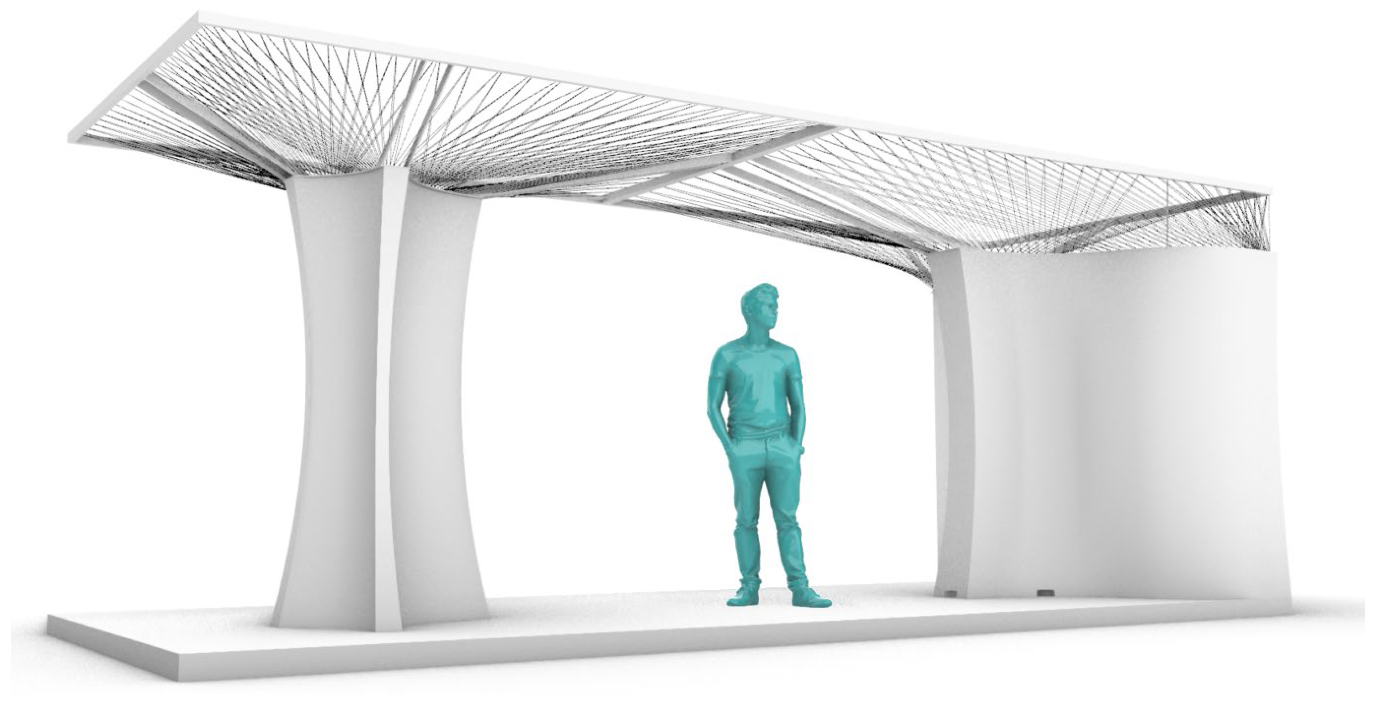
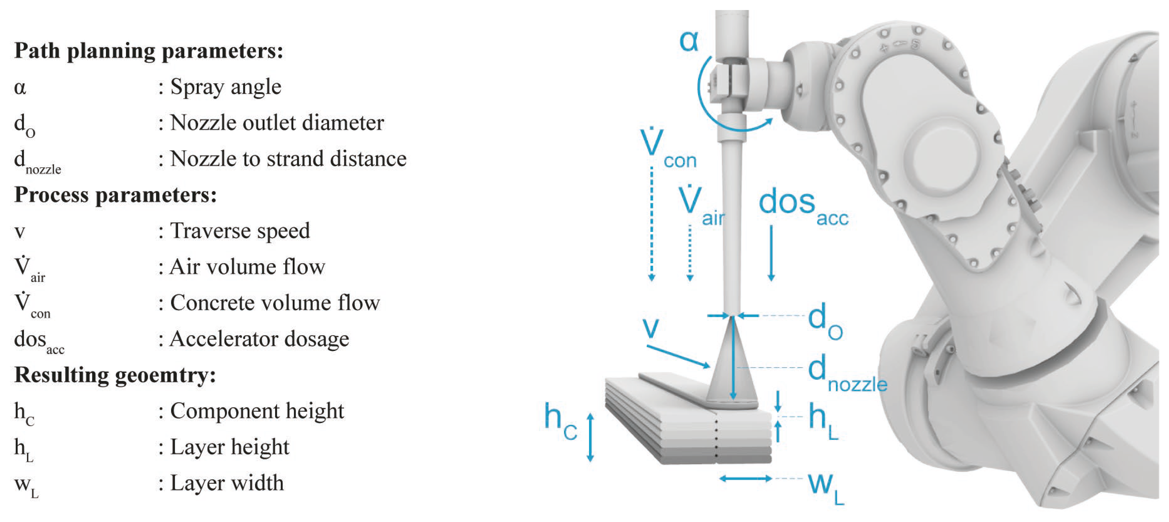

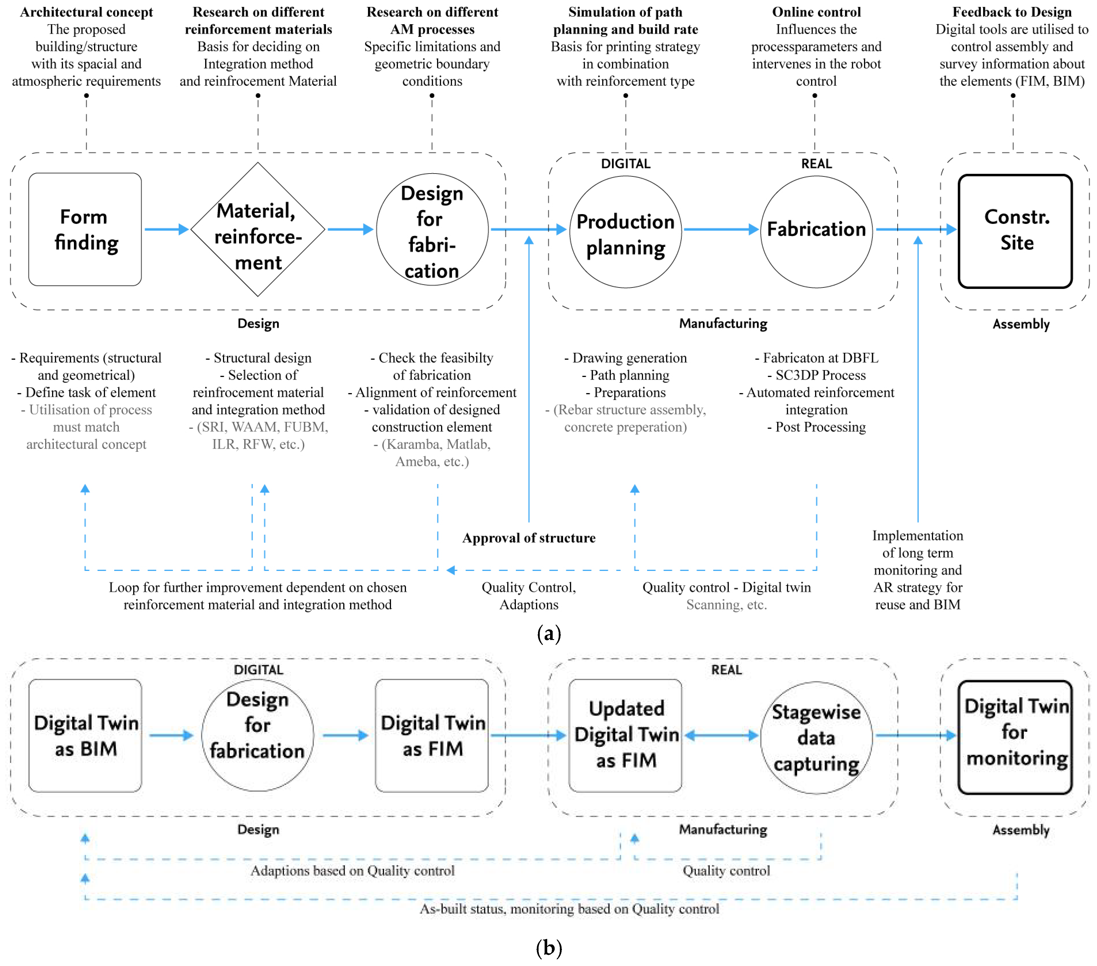
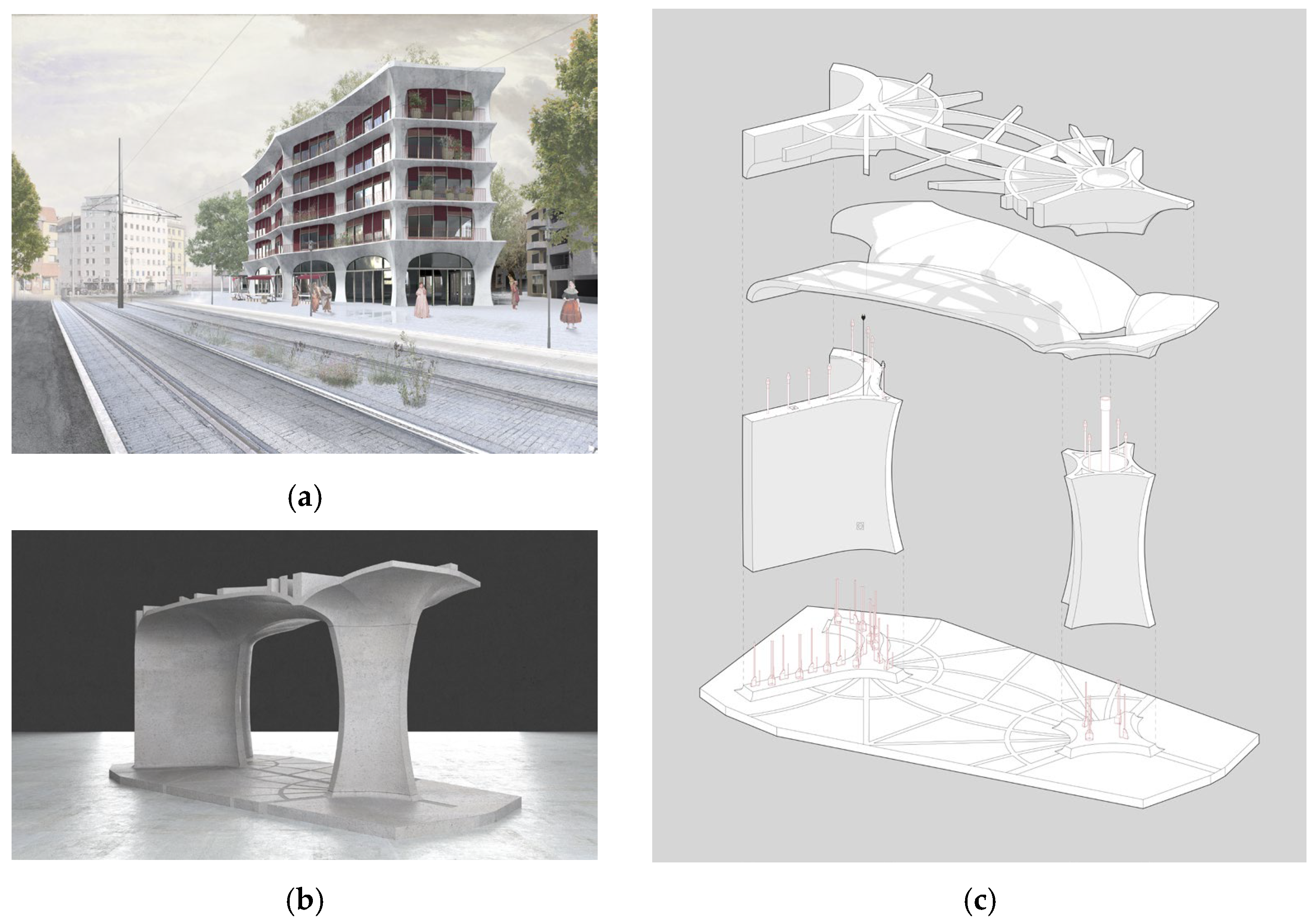
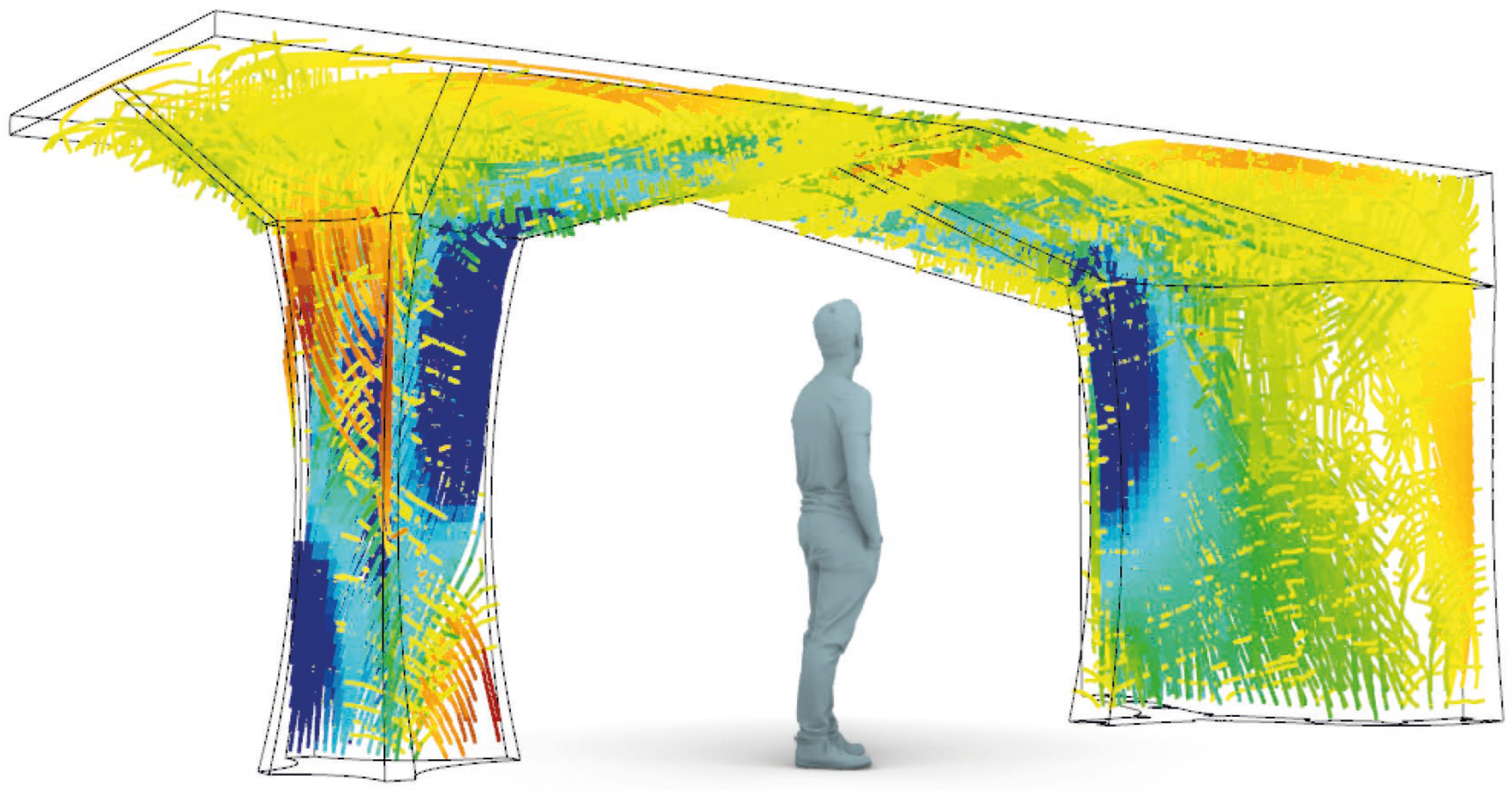
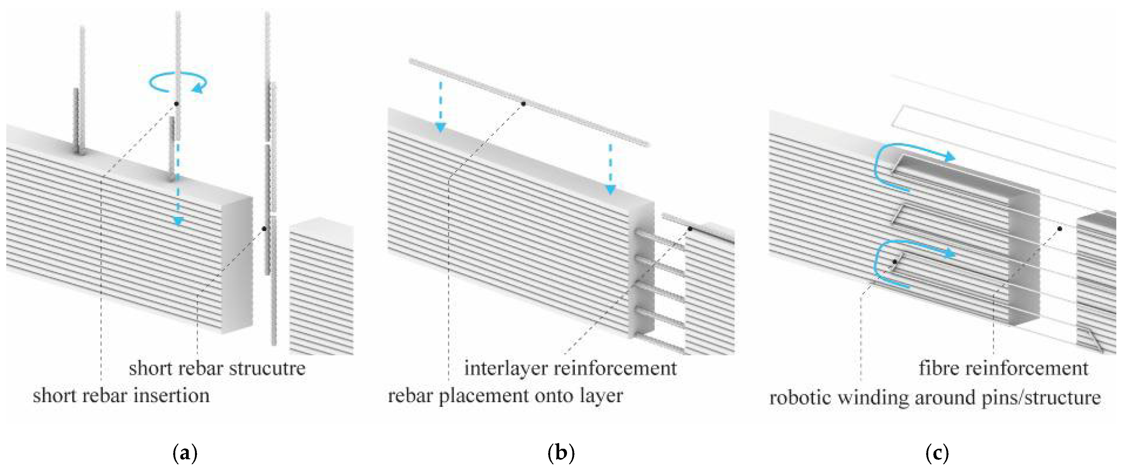
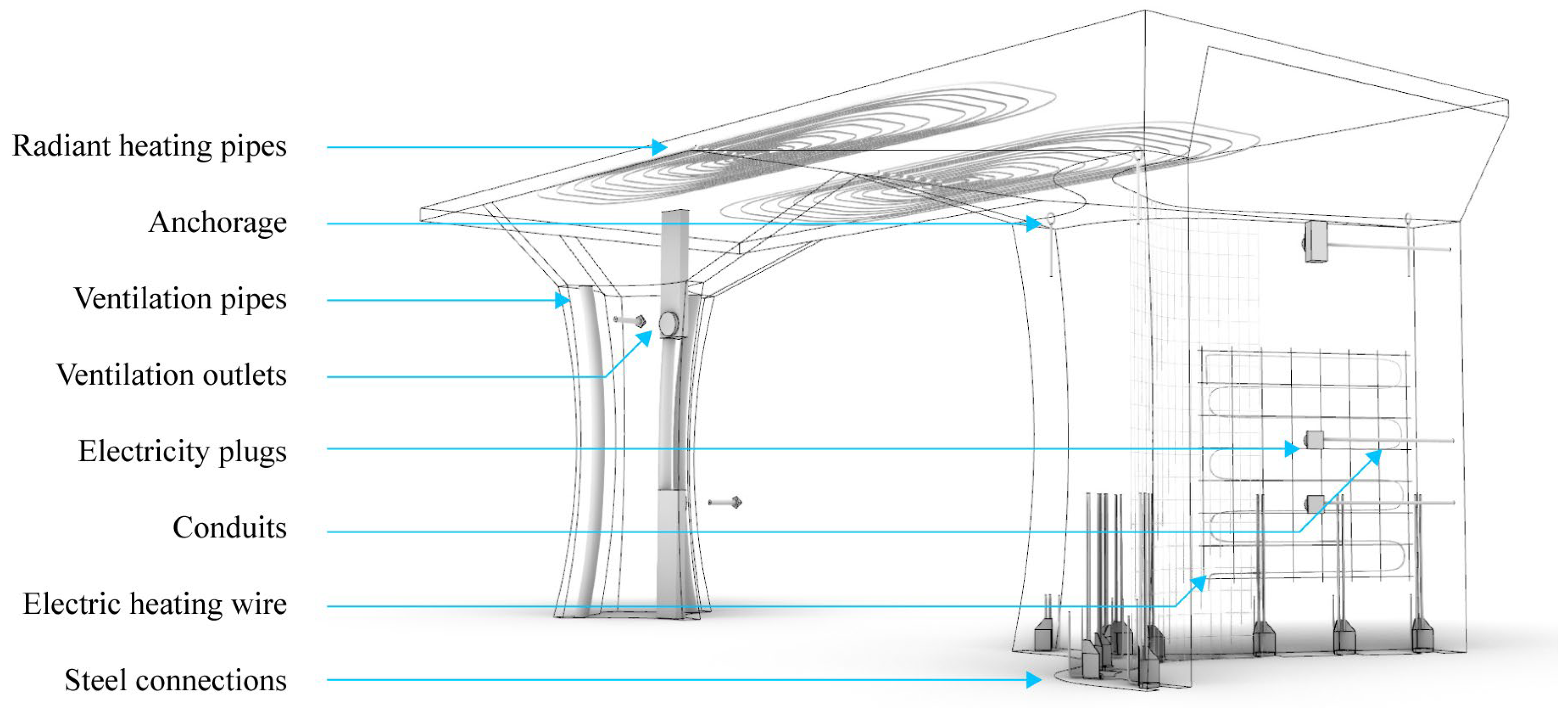
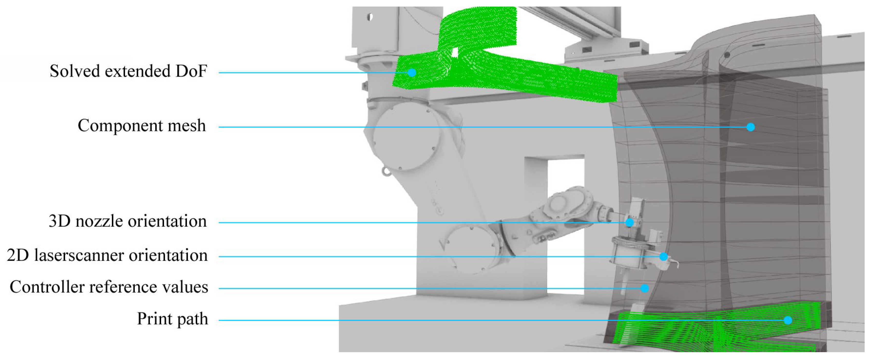
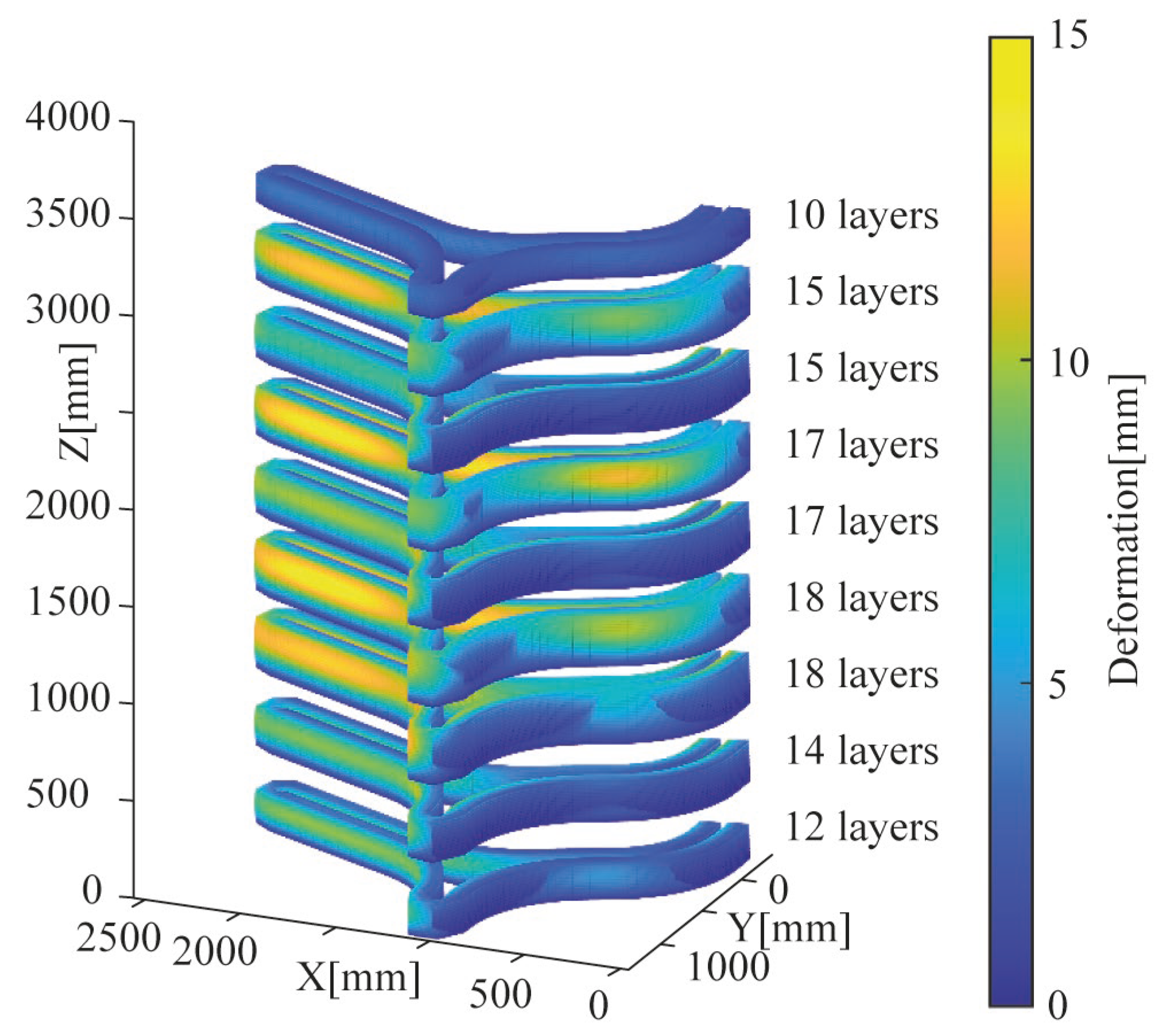
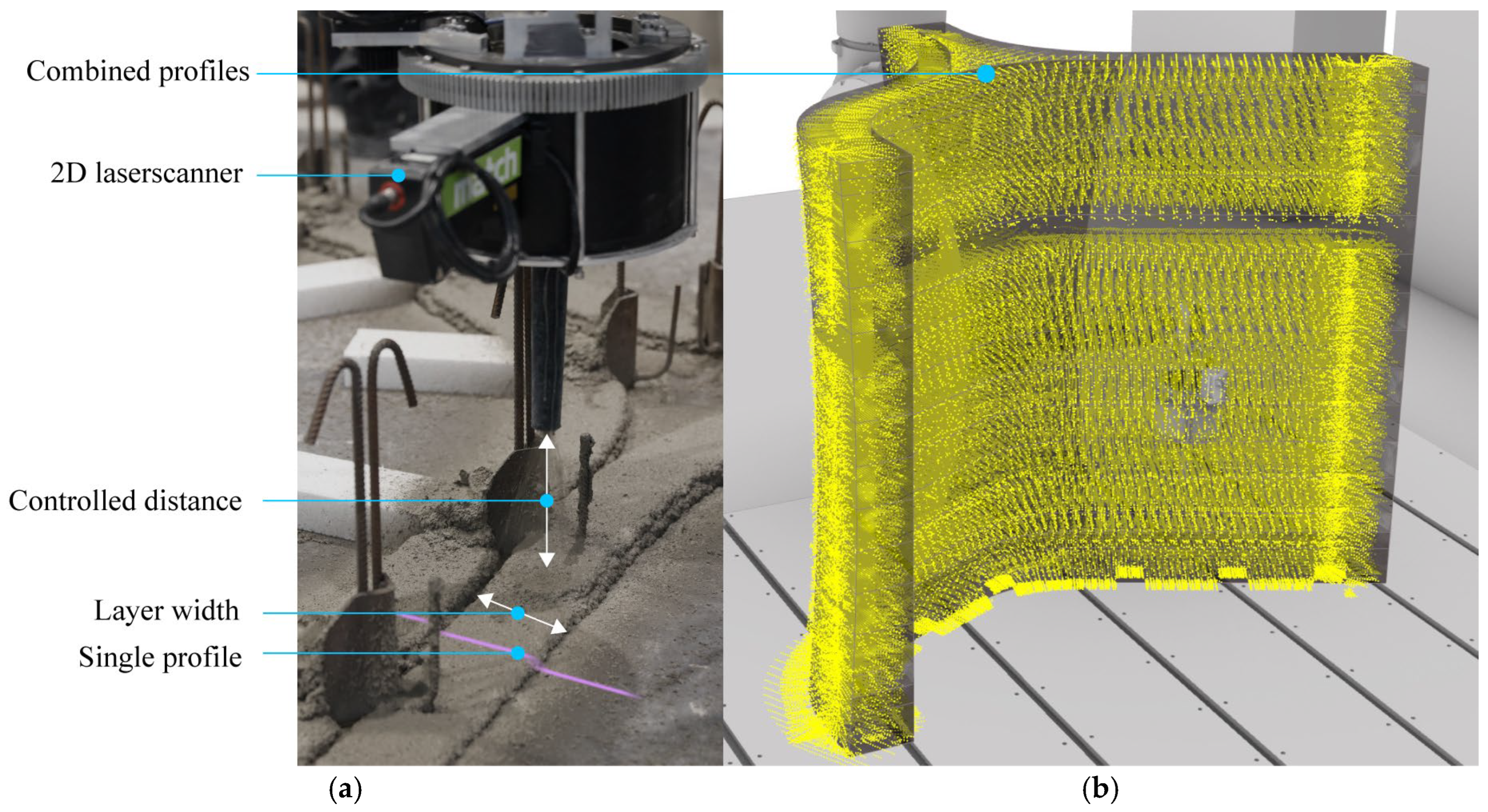

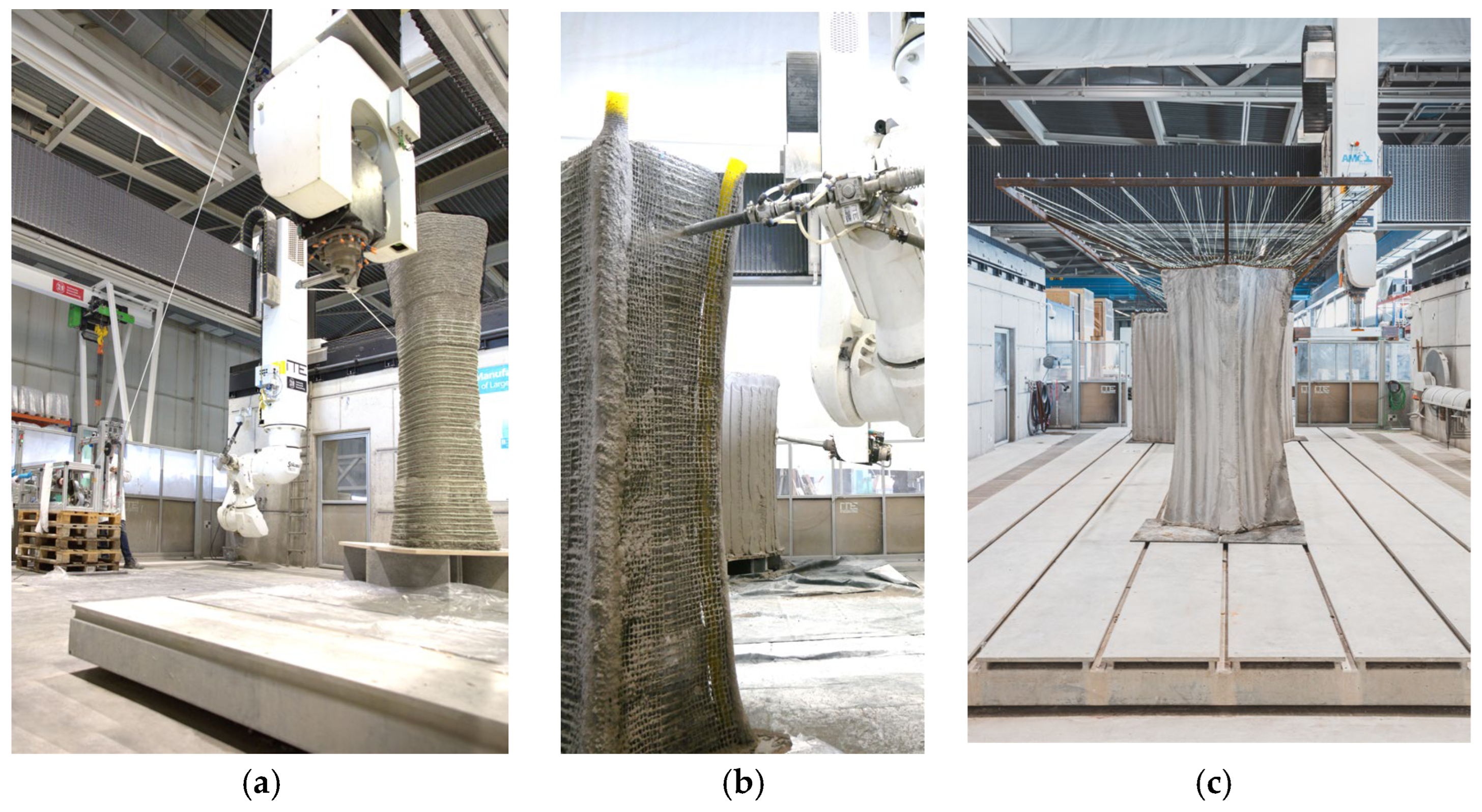
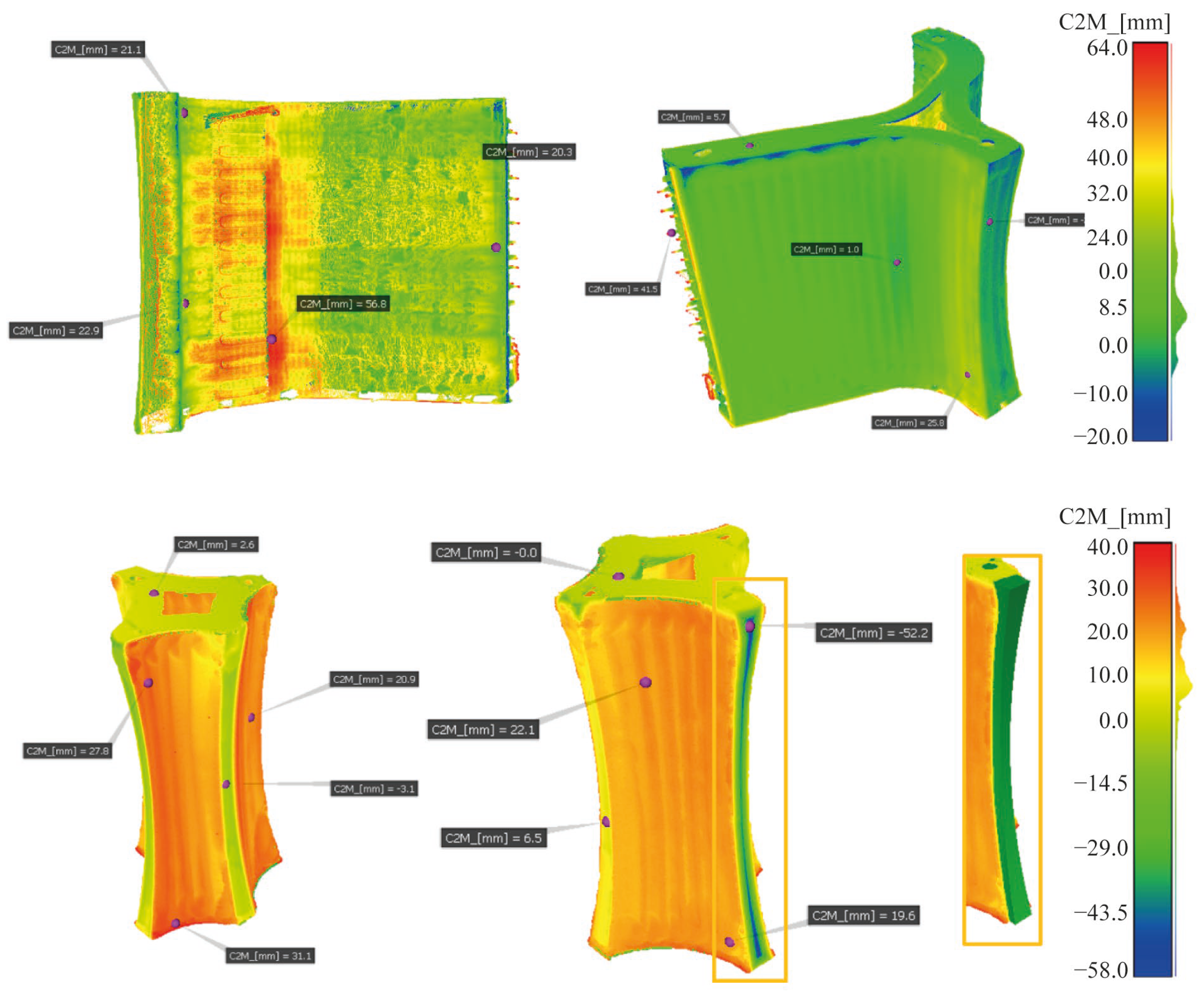
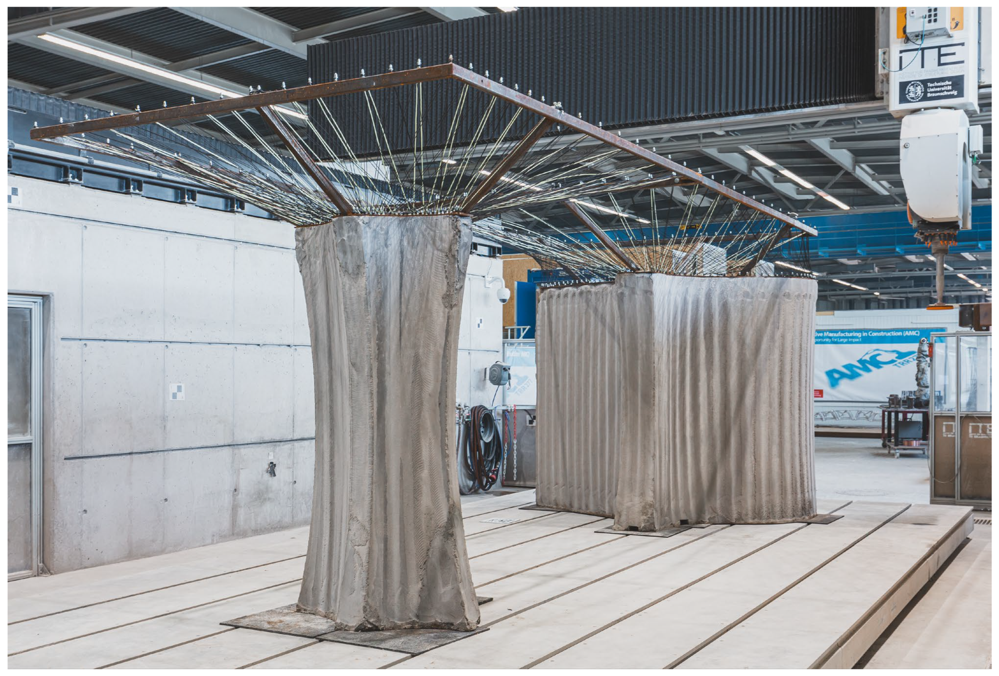
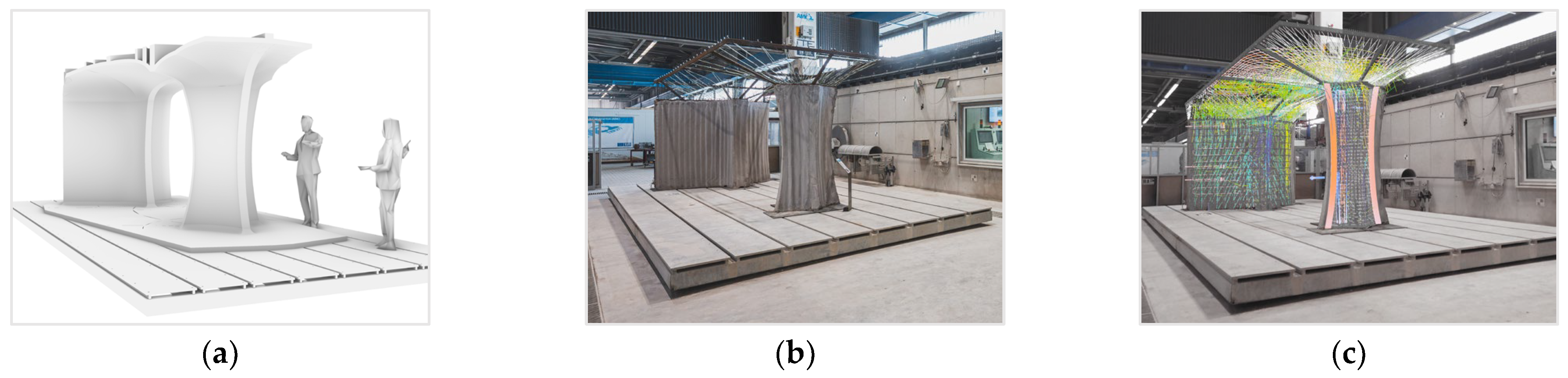
