1. Introduction
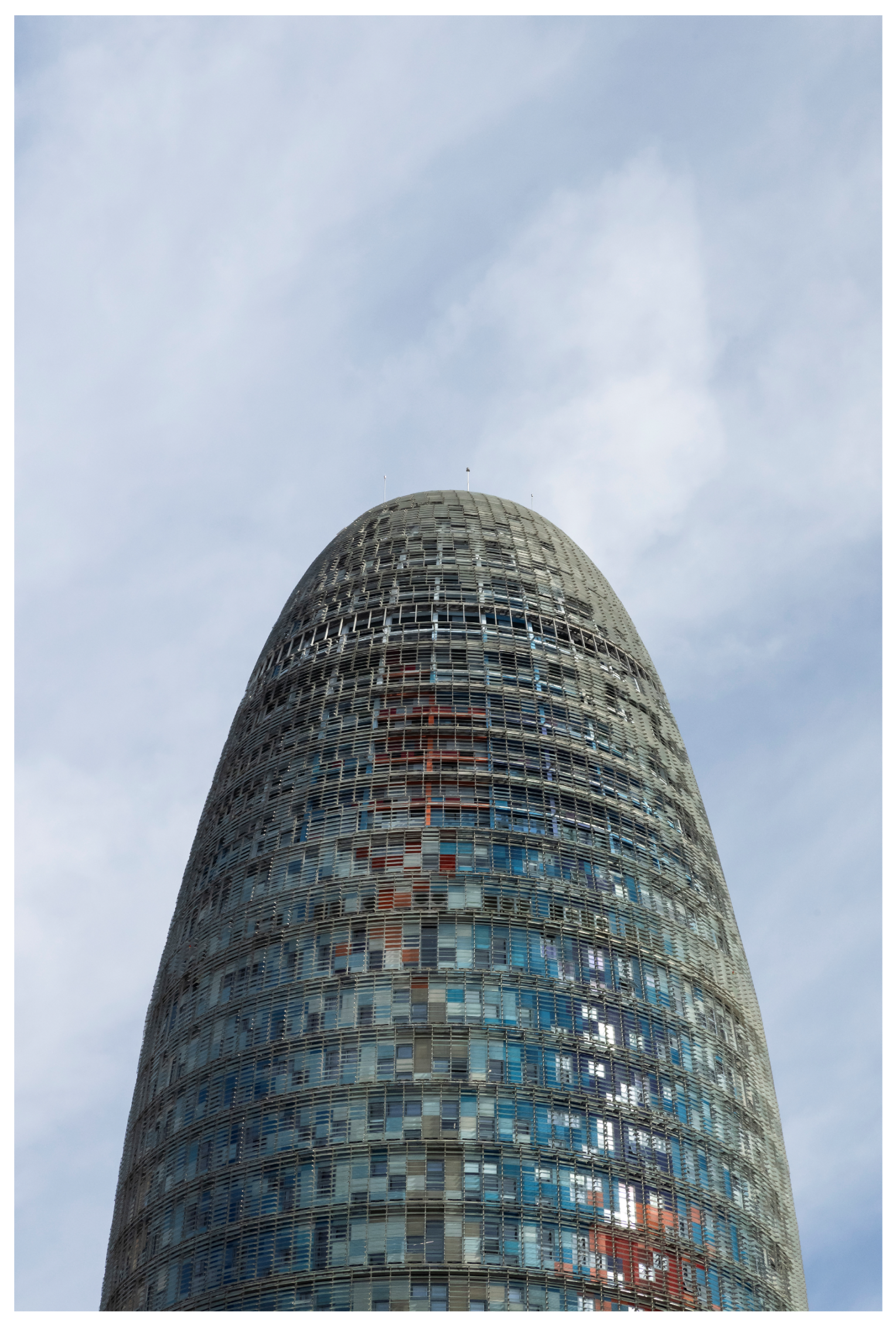
The
Glòries Tower [
1], formerly known as the
Agbar Tower, is one of the tallest and most recognizable landmarks in Barcelona [
2]. Located in Cerdà’s Eixample district [
3], it was among the first initiatives aimed at shifting the city’s center of gravity [
4] towards Plaça de les Glòries [
5,
6,
7]. Soon after, this area saw the construction of the
Nou Mercat dels Encants [
8], the
Museu del Disseny [
9],
Glòries Park [
10], and several other less well-known urban development projects [
11,
12]. The tower, completed in 2005, was the result of an extensive design process. It was designed by the architectural firms
Ateliers Jean Nouvel and
B720 Fermín Vázquez Arquitectos. With a height of approximately 142 m, it is the third tallest service-sector building in the Barcelona metropolitan area, surpassed only by the twin towers of Port Olímpic, which rise to 154 m. The building was constructed to accommodate the offices of the renowned water management company that initially gave it its name. The company later moved to the
“L” building in the Zona Franca, a project by
Arata Isozaki and
CMT. The
Glòries Tower is currently owned by the
Merlín Properties, which has converted the building into a multi-tenant property primarily designated for office use [
13]. The structural design and calculations were undertaken by the firm
Brufau,
Obiol i Moya, known as
BOMA [
14], (now called Socotec) under the direction of architects
Dr. Agustí Obiol i Sánchez and
Dr. Robert Brufau i Niubó [
15], who were, at the time, professors in the structural architecture department at
UPC (
ETSAB and
ETSAV, respectively). The project was proposed between 2000 and 2001, with construction finalized between 2001 and 2005. The total cost was estimated to be approximately EUR 130 M.
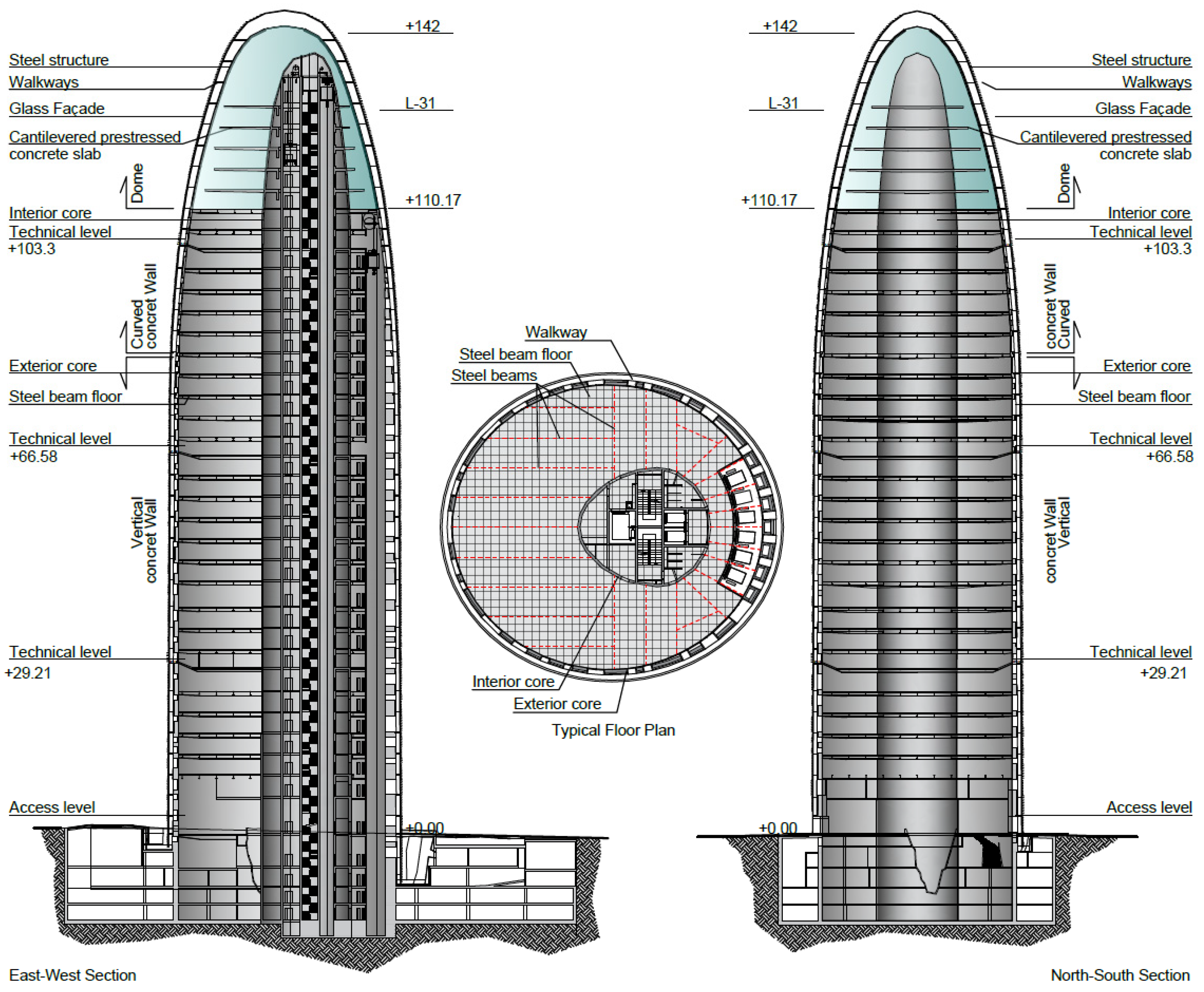
The building (B720 Fermín Vázquez Arquitectos. Available online:
https://b720.com/es/b720-projects/torre-agbar/ (accessed on 15 March 2025)), as can be seen in
Figure 1, comprises four basement levels, extending to a depth of approximately 17 m, about seven meters below the water table [
16]. Additionally, it includes an auditorium located below ground level, beyond the tower’s footprint.
The inner concrete core [
17,
18,
19,
20] houses the service elevators, utility risers, and restrooms, as well as elevators that ascend to the dome. The exterior curved wall, easily recognized by its predominantly white, gray, yellow, blue, and reddish colors, is illuminated at night by approximately 4500 LEDs. It encloses the building and supports the exterior maintenance galleries, which are covered by 52,744 glass slats. The colors are said to have been inspired by structural calculation maps of concrete stresses, although the final design was ultimately designed by the architects.
The basic project brief states the following: “It is a fluid mass that has pierced the ground like a geyser of permanent, measured pressure. The building’s surface evokes water… The material is read in its depth, colored and uncertain, luminous and nuanced. This architecture comes from the earth, but lacks the weight of stone; although it could be a distant echo of ancient Catalan formal obsessions brought by the mysteries of the wind that blows from Montserrat…”.
The space between the two walls, the exterior and the interior, is used for offices and access to the elevators, which are located in the narrowest area. Three technical floors [
21,
22] are provided, one for approximately nine office floors, to reduce thermal losses due to height.
The upper part was originally reserved for the executive offices of the Agbar company. With the change in ownership, a viewing platform is located in this space at level 125, on the 30th floor, where there is also a tensile construction called “Cloud cities”, an interactive work by
Tomás Saraceno (Studio Tomás Saraceno. Available online:
https://studiotomassaraceno.org/ (accessed on 5 April 2025)), which has been open to the public since 2022. To obtain this new space, it was necessary to carry out a new project, in accordance with its new use and its new requirements [
23], which is not the subject of this article.
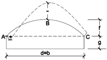
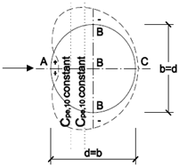
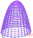
Regarding the dome, as illustrated in
Figure 2, we lacked clear calculation references that would allow us to approximate an approximate cross-section for its constituent elements. Its shape, based on an oval base and with a rather pointed cross-section, makes it rather unique. Its dimensions are similar to those of the Marble Church in Copenhagen, St. Paul’s Cathedral in London, or the Capitol. Regarding similar steel typologies, the Bourse de Commerce dome and the Reichstag dome, although larger, are similar models to the one studied. Regarding pre-dimensioning formulas, there are formulas such as those proposed by Garde and Gehlot [
24] for steel domes with meridians and parallels, or those for geodesic domes, as in various papers on the subject [
25,
26,
27,
28]. The formulas had to be carefully considered, because the shape, the actions, and the type of metal elements could decisively change the result.
2. Description of the Tower’s Structure
The tower’s structure primarily consists of two in situ concrete walls arranged in a ring shape for support:
- -
The curved outer wall, rising 110 m from ground level, has an irregular ovoid shape in plan, with main axis dimensions of 39.40 m and 35.40 m. Its thickness varies between 50 and 30 cm, defining the perimeter of the building. This wall incorporates the distinctive irregular windows that are visible from the exterior. At a height of 76 m, the wall begins to incline inward, gradually transitioning to a shape that aligns with and supports the base of the dome.
- -
The curved interior wall, which in plan takes the form of an ovoid with approximate dimensions of 16.3 by 15.90 m and a height of 132 m above ground level, is offset from the façade. This space houses the elevators and stairs, with wall thicknesses ranging from 50 to 30 cm. Its roof is a small reinforced-concrete dome located beneath the large steel dome.
These two walls, constructed in a continuous process even before the floor slabs, support metal beams that link and stabilize them, ensuring rigid diaphragm action in the horizontal plane. These beams also support the ceilings, which are made of ribbed reinforced-concrete slabs resting on a steel sheet that functions as permanent formwork. Above the outer wall, at an approximate height of 115 m, sits the dome, which serves as the building’s roof. Though it might appear to be a secondary structure, in plan, it takes the form of an asymmetric ovoid measuring 28 by 32 m, with a height of 28 m. The dome is supported by twenty-six nearly equidistant metal meridians aligned with the façade surface. Originally, the company’s executive offices were located at these levels.
Within the space enclosed by the dome, the original design includes three post-tensioned reinforced-concrete slabs, each with a thickness of up to 500 mm, supported exclusively by the inner core. These slabs extend 10 m outward toward the façade without making contact. Initially, the slabs were intended to rest on the meridians of the dome as well; however, this idea was soon discarded in favor of maximizing spatial flexibility.
Thus, the dome [
29] follows a form closely resembling a catenary arch in section. As its designers explained during the development of the executive project, the building takes inspiration from Catalan architectural traditions [
30]. Before defining the structure [
31], the loads and forces it needed to support were first analyzed. Several reference models can be cited, including
Antoni Gaudí’s analytical studies using sandbag models for the Chapel of Colònia Güell, as well as the cable models employed in designing the diaphragm arches of Casa Milà. In three-dimensional structures, a notable example is the
dome of Vitoria [
32], designed by
Joan Margarit and
Carles Buixadé. Although this 76 m diameter spherical structure was built decades ago, it was calculated using a method developed by its authors in 1969, long before modern computational tools provided the reliability available today. Other similar structures were envisioned in the early 20th century by
Richard Buckminster Fuller [
33].
3. Dome Façade Description
The dome’s enclosure is composed of a double-skin system, with an intermediate passageway accessible solely for maintenance and conservation, as illustrated in
Figure 3. The outer skin is a continuation of the building’s general façade, covered with 13 mm thick laminated glass louvers that allow for interior cleaning without requiring a gondola system. On the dome, these louvers have a greater inclination due to their function as part of the roof, yet they maintain the same configuration. The inner layer consists of a modular curtain wall with double 10 mm glass ((15) 5 + 5 mm; the thickness of the outer layer is 10 mm, the air chamber is 15mm, and the thickness of the inner layer is 5 + 5 mm), directly attached to the dome’s metal framework. The glazed surface of the dome covers approximately 2350 m
2. The façade was built by
Permasteelisa (Permasteelisa group. Available online:
https://www.permasteelisagroup.com/project-detail?project=1984, accessed on 15 march 2025). The calculation was performed using Therm software). Their thermal transmittance analysis calculated a U-value (K coefficient) of 2.24 W/m
2K, considering an interior temperature of 20 °C and an exterior temperature of 0 °C. This calculation guarantees the prevention of surface condensation, assuming an interior humidity level of 50%.
4. Action Assessment
During the project phase, the weight of the glass panels was conservatively estimated at 40 kg/m
2, while the walkways were considered to weigh 15 kg/m
2, and the exterior louvers 10 kg/m
2. Snow load was not a significant concern, as surfaces with an inclination greater than 60° are generally exempt from consideration. Consequently, only the central section of the dome required consideration, with a projected load intensity of 40 kg/m
2. Even with climate change in mind, this snow load intensity is relatively high for a city like Barcelona, especially in comparison to other provinces across the Iberian Peninsula. Among Spain’s coastal areas, only the Catalan coast, which includes cities such as Tarragona, must account for a 40 kg/m
2 snow load. By contrast, other coastal regions, such as the Cantabrian coast, are assigned lower values of 30 or 20 kg/m
2, depending on their specific location, as indicated in
Figure 2 of the CTE-SE-AE Additionally, the louvers are set at an inclination of approximately 30° and overlap one another. Given these conditions, a generous estimate of 20 kg/m
2 was used to account for the projected snow load.
Thermal effects have minimal impact on this part of the building, as the metal columns or meridians can be considered to have low rigidity [
34]. Additionally, with plan dimensions of around 35 m, there is no need for special calculation measures, given that these elements are located internally, behind the enclosure. It is also important to note that the dome rests on another structure—the exterior concrete wall—which will expand or contract in a similar manner.
This article does not delve into the topic of seismic activity, as its analysis would be too extensive.
5. Wind Analysis
Wind action poses the most significant challenge for several reasons. The first issue was the regulatory framework in place at the time, specifically NB-AE-88 [
35]. The current technical code for structural actions [
36] did not become mandatory until 29 March 2006, and had not yet been drafted during the project’s development. Nevertheless, Eurocode 1 (EN 1991-1-4) [
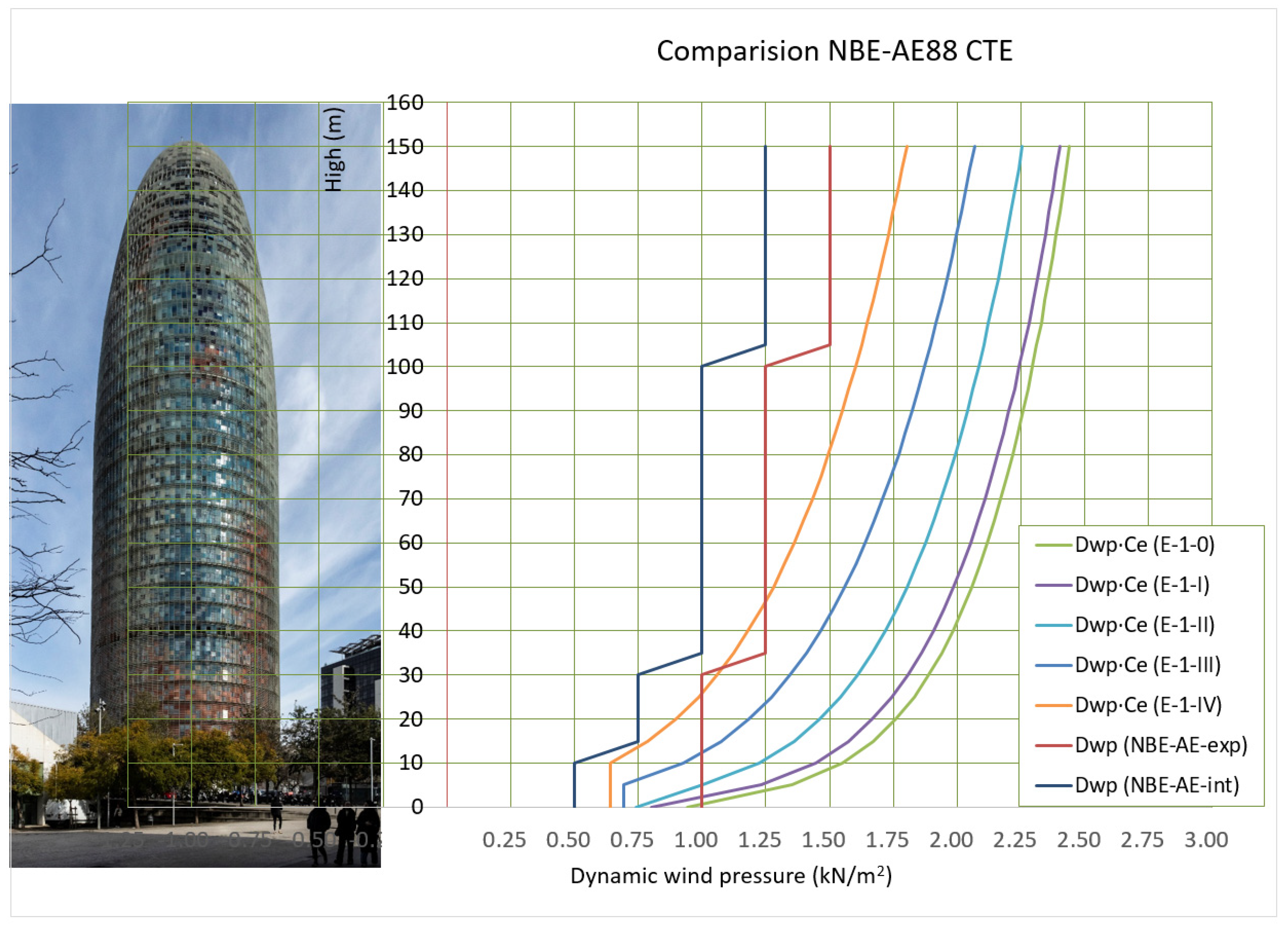
37] which was applicable on a voluntary basis, already outlined wind action considerations that differed from those mandated in Catalonia’s regulations. Specifically, NBE-EA-88 (see
Figure 4), states that for buildings located away from the coastline and exceeding 100 m in height, a dynamic wind pressure of 125 kg/m
2 can be applied. This dynamic pressure was then adjusted using the corresponding wind coefficient, as specified in
Table 1 of the same regulation, for circular shapes and for rough or smooth curved surfaces.
The pressure exerted by the wind decreases slightly when the surface has roughness or when elements are introduced at height to disrupt or create asymmetries in the airflow. In the case of chimneys, incorporating a lightweight spiral staircase or propellers can positively contribute to structural stability. Therefore, the outer skin, composed of single glass panels arranged as louvers, proved to be more beneficial for the structure’s stability [
38] and for determining wind intensity, which is always lower than that of a perfectly smooth curved surface.
The Eurocode is both more precise and more demanding. It proposes five scenarios, the selection of which may be subject to controversy, but a thorough analysis clearly defines them. Curves are numbered from 0 to IV, with 0 representing the most unfavorable case (the current CTE adopts the same five curves but designates Curve I as the most unfavorable and Curve V as the least affected by wind action). When comparing these curves with those outlined in the former NBE-AE-88 regulation, the previous tables [
39] can be derived.
In
Figure 4, the broken blue line represents the regulations in effect at the time for buildings in a “Normal” situation, while the red line applies to buildings classified as being in an “Exposed” situation. An exposed situation encompasses locations such as coastal areas, topographic ridges, narrow valleys, and plateau edges. Additionally, it was specified that in particularly exposed topographic conditions—for instance, high mountains, gorges, or cliffs—higher values may be necessary and should be determined through a specialized study. Consequently, the appropriate exposure classification to be applied in this case would be “Normal”. The other curves represent the different options offered by the Eurocode, covering a wider range of positions. It can be observed that, under current regulations, almost any scenario results in higher wind pressure than what was in effect at the time. Although the NBE-AE-88 value was regulatory, a pressure of 180 kg/m
2 was adopted during the project phase for all parallels. This decision matched Eurocode 1, Curve IV, for the roughness grade associated with urban areas. The building is located a little over 1.5 km from the coast. This wind pressure, corresponding to the tower’s maximum height, was applied uniformly from the base of the dome to the keystone. The center of gravity of a catenary’s interior form is closer to the base than to its average height, it can be understood that the final wind pressure considered was even midway between curves IV and III. Annex A of EN 1991-1-4:2005 (Eurocode 1.4) provides images that support this decision. A wind tunnel was not commissioned, but basic checks were performed using a calculation program called GID, which confirmed these pressures. The knowledge that the structural design consultancy had acquired in the 1990s on another similar high building located in Barcelona (Agustí Obiol was the Catalan partner responsible for overseeing the calculations and subsequent construction management of the Hotel Arts in Barcelona, a project by SOM architects), which was previously compared with more advanced American standards, concluded that the wind loads, greater than 45% of the then-current Catalan standards, were adequate.
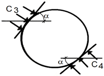
Finally, calculating the Cp coefficient for each point of the dome was necessary. Both regulations establish calculation values based on the angle between the considered wind direction and the tangent plane at the analyzed point. While the values are largely similar,
Table 1 reveals slight variations. Specifically, the AE-88 reaches suction coefficients of 2.0 within a range of up to 30°, whereas the CTE, in certain specific cases, reaches a value of −1.7. In the building’s nearly 25-year lifespan, there have been no problems related to wind exposure on this element. The wind speed required by current national regulations for multi-story buildings is excessively high; the zones on the national map should be adjusted.
Another issue in transferring the actions to the calculation model was the geometry of the construction itself. At the time of construction, matrix calculation programs for bar elements were not as advanced as they are today, with wind loads now able to be calculated automatically by the software. To streamline the analysis, a spreadsheet was used to generate the loads, enabling quick transfer into the calculation program. The pressure and suction coefficients were estimated based on the polar angle, as the surface is curved not only in plan but also in section. It is also worth noting that the wind should be considered with an angle variation of plus or minus ten degrees and that the exterior façade louvers could introduce inclinations that were either more or less unfavorable for the calculation.
The Microsoft Excel formula used to calculate the polar angle is shown below:
where
αh is the plan angle of the surface;
αv is the section angle of the surface.
Using this polar angle, the wind coefficient for a closed structure’s surface was automatically obtained in
Table 1 of the NBE-AE-88, considering the surface to be rough. To input the actions into the calculation program, over 400 action lines were generated for each scenario, making it easy to modify the values at any time if adjustments to the intensity, incidence angle, or orientation were needed.
Once the loads and shape were determined, the next step was to define the supporting structure that would enclose the building.
6. Searching for the Structural Form
Between 2001 and 2002, multiple meetings were held between the architectural and structural teams to determine the most effective way to ensure the roof’s stability [
40]. From the very beginning, it was clear that the oculus had to remain open. The best way to resolve the junction of so many bars is, without a doubt, to eliminate it altogether and replace it, with a compression ring positioned far enough away to prevent the meridians from converging at a single point. A common solution in the early 20th century for addressing this issue was to use a cast iron piece, onto which the meridians were bolted along its perimeter-bearing surface. This approach prevented excessive heating at a central point caused by the concentration of welds. Welding on cast iron can be performed effectively if an appropriate welding system is used [
41].
Numerous proposals were analyzed, with the emphasis placed more on the structure than on the shape. This document presents only four models, as they are the most interesting and diverse for understanding the design and calculation process. Each version was thoroughly reviewed by all stakeholders, gradually refining the structure toward a final proposal.
The calculation software used was Robot V6, running under a licensed version in Microsoft’s MS-DOS environment. The images included in this article were obtained using an educational license of Autodesk Robot [
42], used exclusively to recover information from twenty years ago for the preparation of this article.
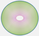
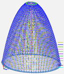
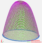
6.1. First Version, Trussed Dome: Basic Project
The first proposed design featured 20 spatial triangular meridians and 20 flat triangulated parallels arranged in a lattice structure. Additionally, three secondary meridians were inserted between each of the 20 main meridians, and one simple parallel was placed between each of the 20 main parallels. A simple element refers to a component consisting of a single profile with low inertia. By the end of the process, the final structure comprised a total of 11,980 bars. The use of such a large number of bars allowed for very thin profiles, specifically RHS-200 × 50 × 4 bars and solid diameters of 16 mm. The proposed structure had a total steel weight of 91,943 kg but posed challenges in ensuring adequate fire protection for the metal profiles [
43], as the ϕ16 bars had a particularly high shape factor. (The “shape factor” is the ratio of the perimeter of a member exposed to fire to its cross-sectional area. The cross-sectional area will always be a constant value intrinsic to the section, while the perimeter can vary depending on the faces exposed to fire. The concept of “massiveness” assumes that the entire contour is exposed to the action of fire.) At the beginning of the project, the required fire resistance was estimated to be R-30. However, as we will see later, this requirement was increased following several discussions with the fire department. The final shape of this first proposal, shown in
Figure 5, resembles the bow of a zeppelin but made of steel and more reinforced.
Furthermore, both the manufacturing cost and the installation process became overly complex. The structure needed to be assembled at a minimum height of 120 m, posing the usual challenges associated with working at height. Another issue with this initial solution was that the structure clashed with the prestressed cantilever slabs, as it reached a depth that was incompatible with the project requirements—specifically, 600 mm between axes and 708 mm in actual size—making it necessary to reduce them. This issue, along with fire safety considerations, was decisive in proposing a second, radically different structural solution, which is discussed later.
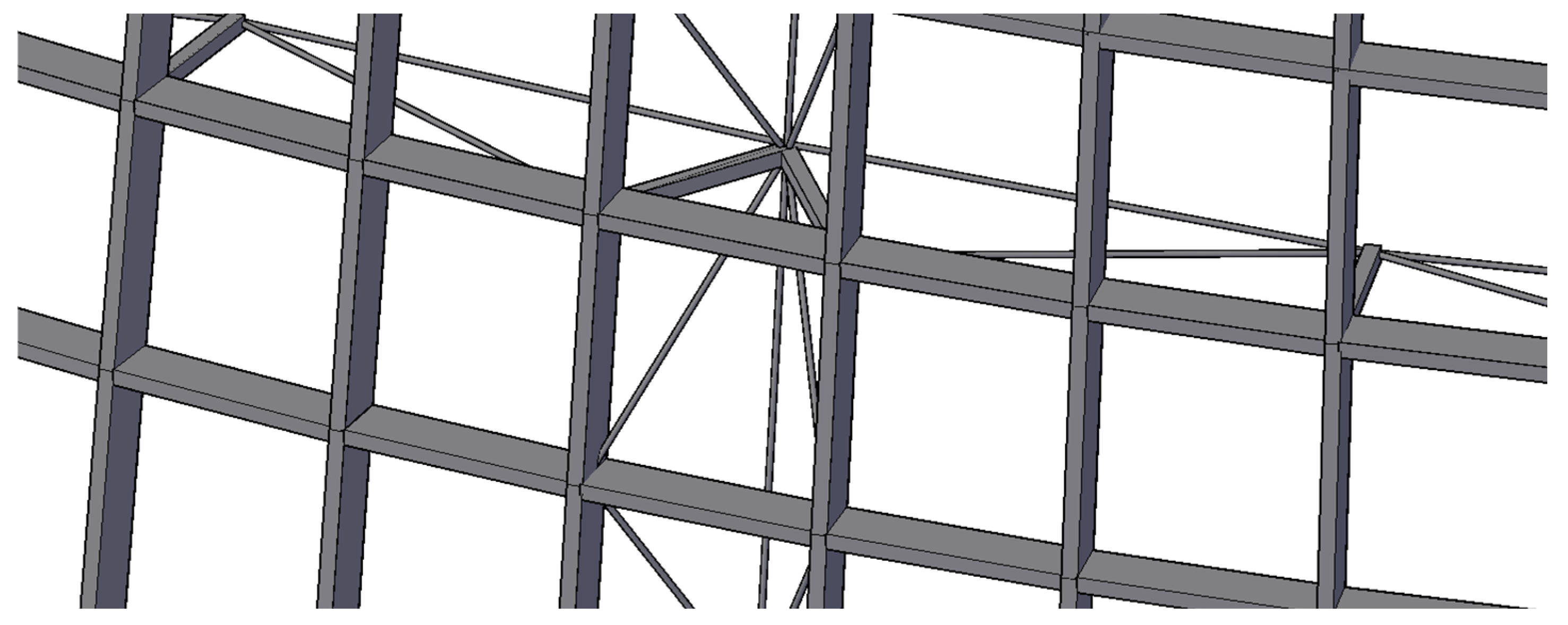
The proposed joint detail, though not meticulously developed since the solution was ultimately discarded, is shown below in
Figure 6. A 16 mm diameter bar has a shape coefficient [
44] (commonly known as massiveness) of
where
r is the radius of the solid bar;
M is the shape factor (massiveness).
Figure 6.
A diagram of the proposed joints for the first version. The compositional form of the structure can be understood as a simple dome reinforced locally with a second chord, and with vertical and diagonal elements.
Figure 6.
A diagram of the proposed joints for the first version. The compositional form of the structure can be understood as a simple dome reinforced locally with a second chord, and with vertical and diagonal elements.
For tubes, considering them exposed on all four sides,
where t
RHS is the tube’s wall thickness in meters.
In general, achieving 60 min of protection with intumescent coatings was difficult for such high shape factors [
45]. Moreover, considering that these are closed sections, which require a thicker protective layer than open sections, the challenge becomes even greater. Since the structure had to be visible, using gypsum panels or vermiculite was not an option. Applying such a thick layer of paint would not only increase material costs but also result in a poor esthetic finish for the dome. Intumescent paint tends to develop a textured finish known as “orange peel” when applied in thick layers and is also susceptible to impact damage [
46].
Therefore, if this option was chosen, it would be necessary either to increase the thickness of the metal elements to reduce their shape factor—further increasing the cost of the structure—to conduct a performance-based CFD analysis [
47], or to install sprinklers. One potential advantage is that, in the event of a hypothetical collapse, the failure of a joint could be managed more effectively and with greater control compared to the other solutions discussed below [
48].
For this version, we propose a construction price of approximately EUR 500,000, updated to the current date, with an ideal construction period of four months.
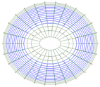
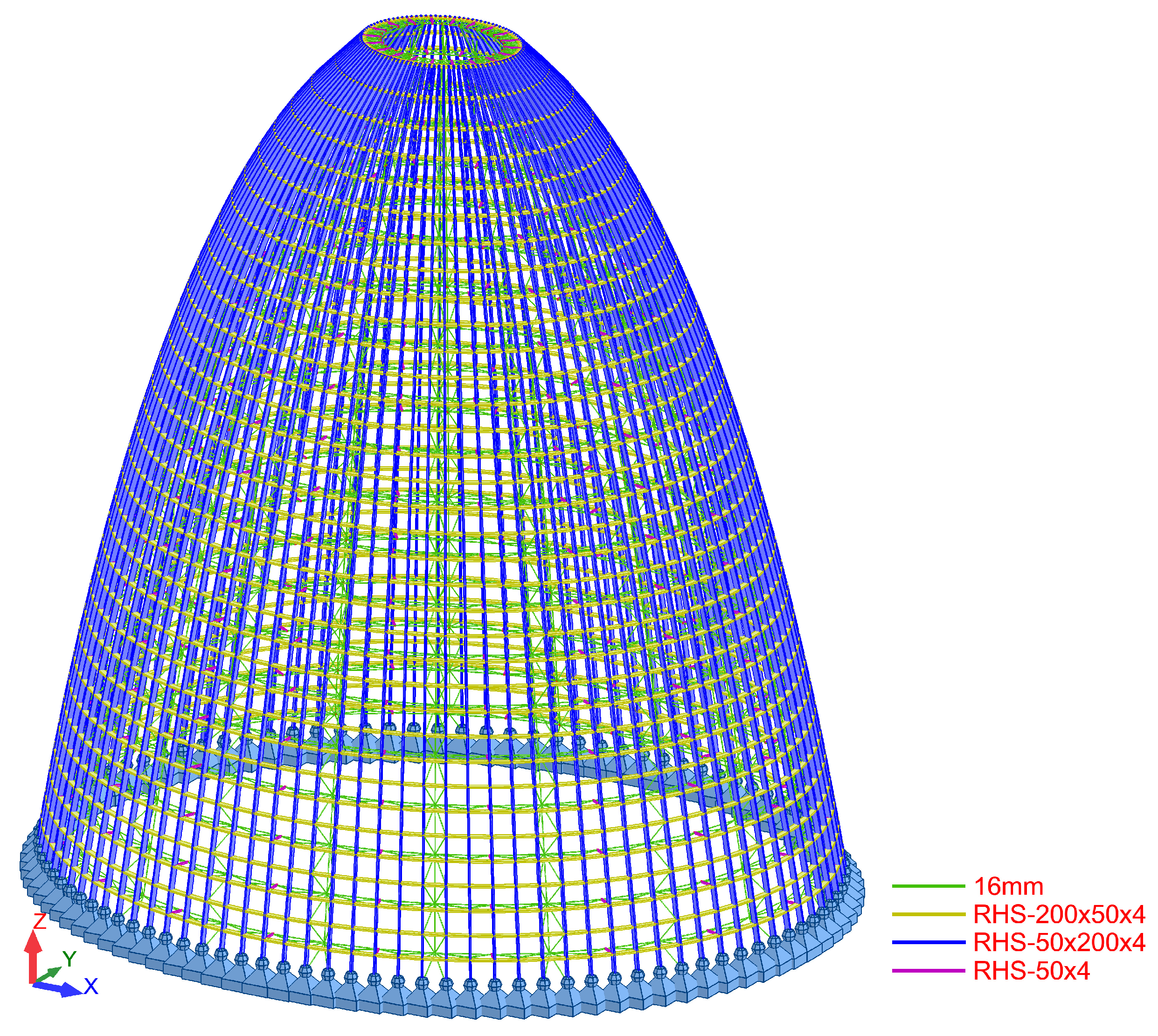
6.2. Second Version, Fine-Shell Dome: Basic Design A
The second version examined in this article follows a shell-type solution. The parallels act as rings that independently prevent the buckling of the meridians, which transfer gravitational loads to the top of the concrete façade. The version presented—one of several—uses a single profile type, 200 × 50 × 5 mm, for both the parallels and the meridians. The 200 mm dimension was consistently oriented perpendicular to the surface. This solution addressed several issues identified in initial tests, including accommodating the passage of prestressed concrete slabs and simplifying the construction process, as the profile connections were easy to assemble. Additionally, it was significantly lighter than later versions. Nevertheless, some challenges remained, such as the external walkways, which generated significant moments at their connection points, necessitating the reinforcement of certain joints. Fire protection was also a concern, as a 5 mm tube wall had a shape factor of 200 m−1.
The calculation model consisted of 14,836 bars and had a total weight of 158,424 kg. Once again, the increase in weight was an issue, but as will be seen later, an even greater weight was required. The bars created gaps of only 1 m × 1 m at best, which neither favored the view of Barcelona nor facilitated the installation of the glass enclosure. While this might have seemed like a regression in the project’s evolution, it was actually a necessary transition toward the final version: a single “shell” with no additional thickness beyond that of the profile itself. As a result, it was key to use deeper profiles while increasing the spacing between them. The final shape of the dome in this version is shown in
Figure 7.
The most significant difference between the first and second options is the behavior of the meridians. Initially, they functioned in compression and tension—common in triangulated truss structures. However, in the second option, they transitioned to working in combined compression, a characteristic feature of simple profiles.
In this case, a construction material price of approximately EUR 830,000 is proposed, updated to the current date, with an ideal construction period of 5.2 months.
6.3. Second Version, Medium-Shell Dome: Basic Design B
This second version A was excessively difficult to build due to the number of joints, so before analyzing the impact of fire protection and the admissible deformation of the glass, an intermediate solution was analyzed, which went from 106 meridians to 52, and from 69 parallels to 35. The comparison between the two solutions that can be seen in
Figure 7 expresses the superiority of this second option. Material execution price: EUR 665,000; construction period: 3 months.
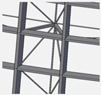
6.4. Third Version, Steel Frame: Executive Project
The third version described in this document is the one that finalized the executive project. At the time of construction, there was a more comprehensive understanding of the space, enclosures, walkways, and various constraints that the dome’s structure needed to accommodate. The earlier versions can be seen as incomplete proposals that progressively evolved to the final solution.
A less dense and more open design was chosen to enhance the feeling of a private viewing platform, with glass panels reaching maximum dimensions of 3.70 × 1.90 m. This stage also marked the integration of the walkways, which had previously been considered only as loads on the joints but were now designed as cantilevers embedded into the shell. Another key factor was cost reduction, not necessarily in terms of the total steel weight but by minimizing the number of connections. Finally, the required 90 min fire resistance was addressed by considering the shape factor of the sections and increasing the tube wall thickness, ensuring better compatibility with the application of intumescent paint.
The final version, prior to construction, had a weight of 277,941 kg, with the model consisting of 910 bars, excluding the cantilevers. While the reduction from 14,836 to 910 bars does not represent exact data, it does illustrate the significant simplification achieved in terms of connections, as each bar in the calculation linked two structural nodes.
The main difference in this option lies in the use of two different profile types:
- -
The first type was a box section formed of two UPN-300 profiles welded together and attached to an IPE-330. This combined profile was positioned on the exterior of the shell, in the cold zone. It was also used for the meridians supporting the walkways, applied to every other one.
- -
The second type was a box section made of two UPN-300 profiles, similar to the first but without the IPE. This profile was placed on the interior side of the dome.
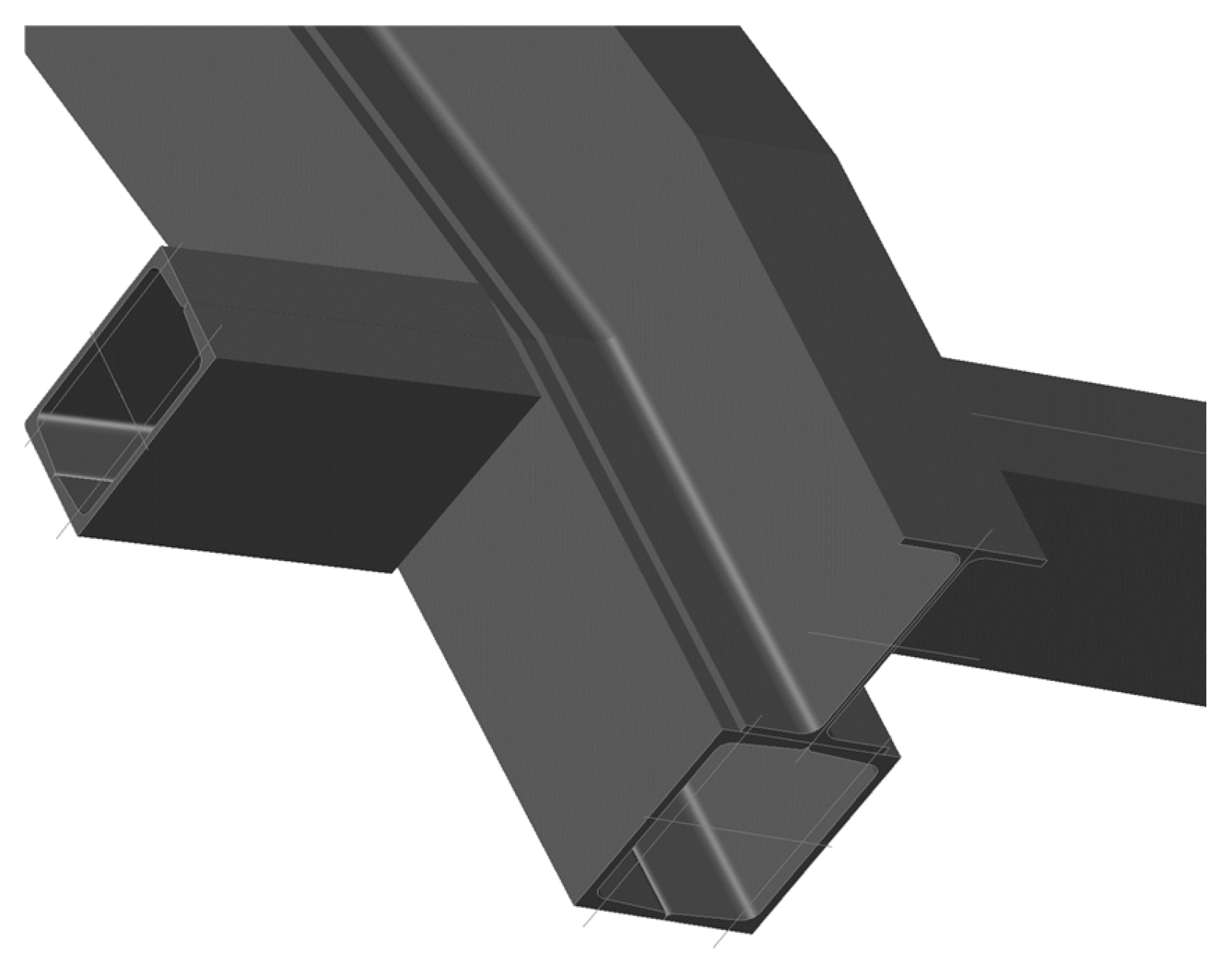
The decision to use a tube formed of two UPN profiles instead of a single RHS was driven by the slight advantage of bending a UPN profile before welding, as well as its sharp edges, which contrast with the rounded edges of an RHS. This approach significantly simplified the connections, where each profile joined another with the same characteristics, eliminating the need for stiffeners or additional plates. Since the profiles were curved, all connections remained tangential, preventing issues with section rotation—a frequent challenge in non-orthogonal spatial structures composed of planes. Bolted connections were generally avoided, except for potential joints between the meridians and the concrete façade. Architecturally, this solution also resulted in a highly refined connection. The final shape of this version is illustrated in
Figure 8, while
Figure 9 presents the typical joint detail.
The lower connections to the concrete façade were designed to be flexible with respect to bending moments. While full embedding could be achieved with proper concrete reinforcement, this approach provided advantages in terms of the final deformations and stress distribution in the profiles. Each meridian experienced a reaction force between 218 and 438 kN under ultimate limit state (ULS) conditions, always in compression. Bending moments were relatively minor, reaching a maximum of 55 kNm, also in ULS.
Material execution price: EUR 1,300,000; construction period: 1.7 months.
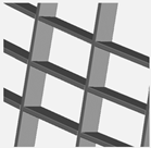
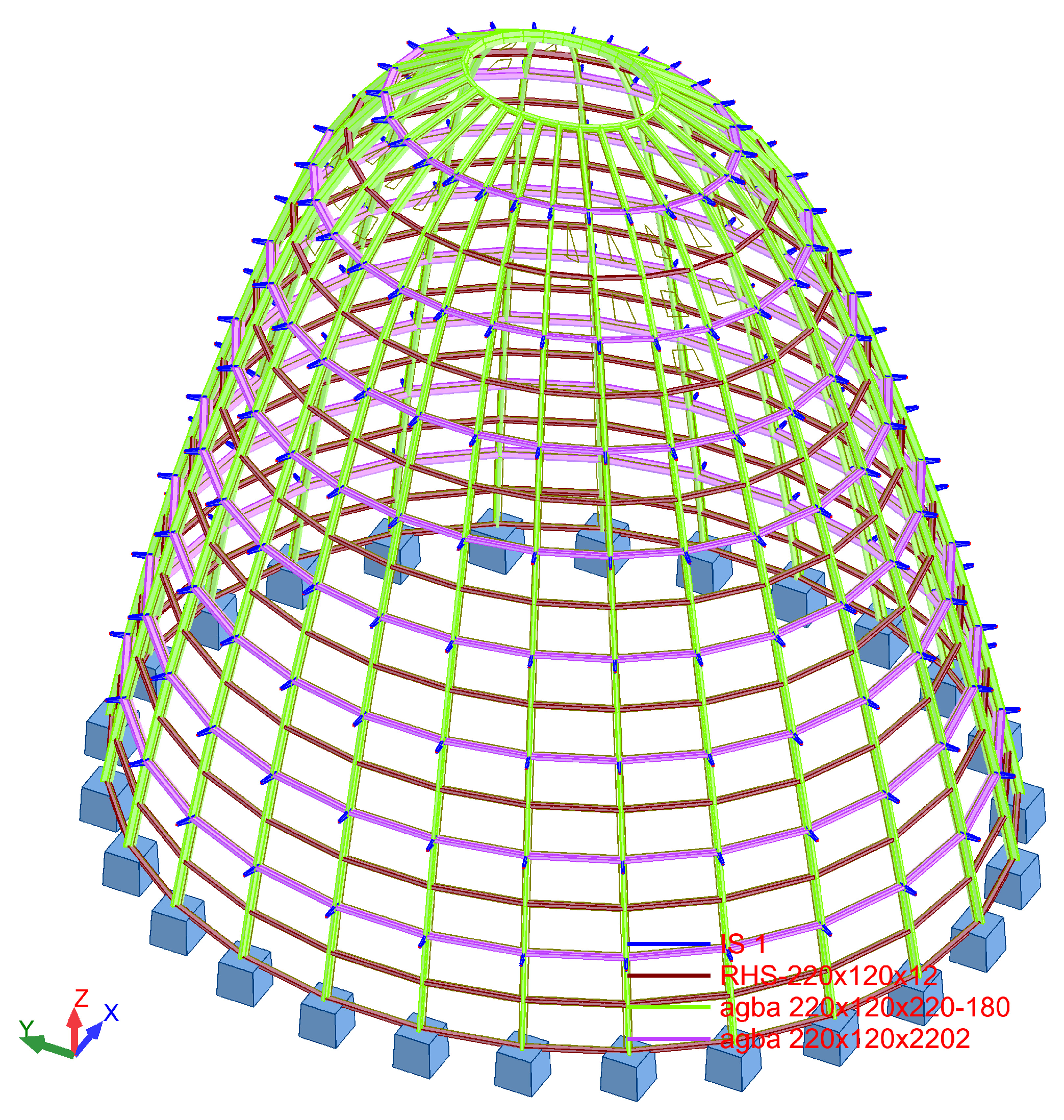
6.5. Fourth and Final Version, Braced Pillars: Built Project
The fourth and final version described corresponds to the as-built solution. In essence, it is a carefully refined adjustment of the sections used in the previous design, where closed profiles were replaced with open ones. This adjustment reduced construction costs, simplified assembly, and, most notably, facilitated the transportation of the structure from the workshop to the construction site. The reality is that, in the case of the third proposal, the need to join UPN profiles, sometimes requiring full-penetration butt welding, along with the bending of both sections forming each meridian, significantly increased the final cost. Closed profiles, on the other hand, required a greater paint thickness than open profiles. Moreover, a large portion of the steel section was positioned along the neutral axis, where it did not contribute to bending moment capacity. The issue was not element compression, but rather, insufficient bending inertia.
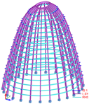
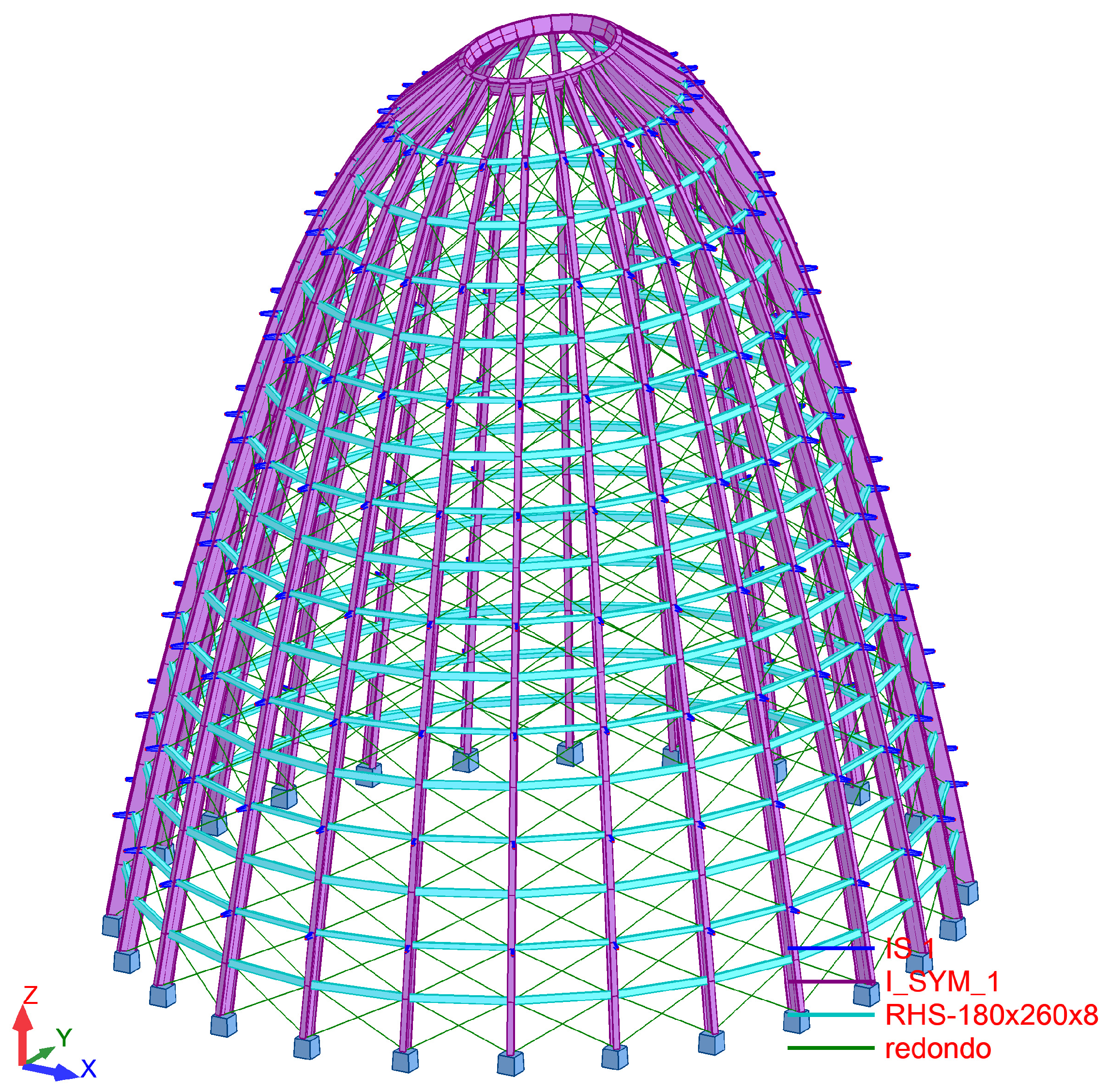
Considering all of the above, a simple open section was proposed consisting of a single double-T profile with a greater height, and with the flanges oriented parallel to the glass. For the meridians, a profile was used with exterior dimensions fitting within a 640 × 220 mm rectangle, while for the parallels, a hollow rectangular profile measuring 180 × 260 × 8 mm was utilized.
It can be noted that the response of this dome was noticeably different from that of the previous one. The meridians were reduced to allow the window frames to function properly. As a result, the parallels lost inertia, and the meridians had to be increased. Specifically, the total inertia of the meridians increased from 1,146,973 cm4 to 2,503,437 cm4 in version 4, representing an increase of 218%, while the inertia of the parallels decreased from 1,153,229 cm4 in version 3 to 110,670 cm4 in the final version, which accounted for just 9.5% of the inertia of the previous solution.
The curvature radius of the profiles was not particularly sharp, meaning the bending process would not present any problems. However, all sections of the meridians were ultimately built with a polygonal shape. This decision was made for three main reasons: the change would not be noticeable, construction costs would be reduced, and since the glass frames were positioned within the profiles, the frame would continuously rest on the profiles, simplifying the detail. A minor issue arose with the profile change: the structure would lose some torsional capacity, as a double-T profile has lower secondary inertia than a rectangular tube, and this loss might negatively impact the connection with the glass. This issue will be addressed in a later section. The final structure is shown in
Figure 10.
In this version, the profiles had double the inertia of the previous one, while the meridians significantly reduced their inertia, resulting in more refined detail for the façade. Moreover, due to the open-profile design, the meridians required less intumescent paint for fire protection than would be needed for a closed profile with the same shape factor.
The current understanding of progressive collapse in welded metal connections on site is far greater than that considered at the beginning of the century. The collapse of the Twin Towers in New York, for example, occurred when construction had just begun, in 2001, and sparked a debate very similar to that of any high-rise building then under construction. Research on this problem began around the 1970s, but became more specific and gained greater relevance in the second decade of the 21st century, after the tower’s construction [
49,
50]. The highest-quality steel grade for working at high heights with low temperatures and in unfavorable welding conditions is S-355-J0. Despite the above, the ductility of the connection was demonstrated, depending on the consumables used for the type of steel employed. Likewise, the welds performed on site were thoroughly reviewed. The self-weight of the steel structure, in the event of failure, can be supported by the lower floors in the event of an accident. The structure is independent of the concrete.
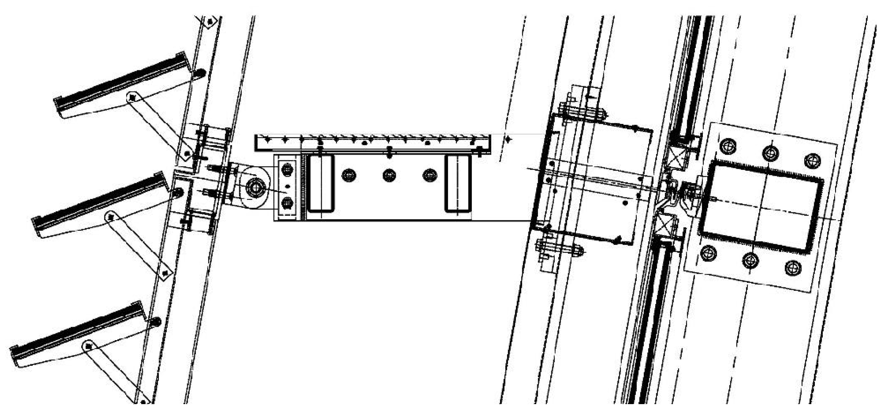
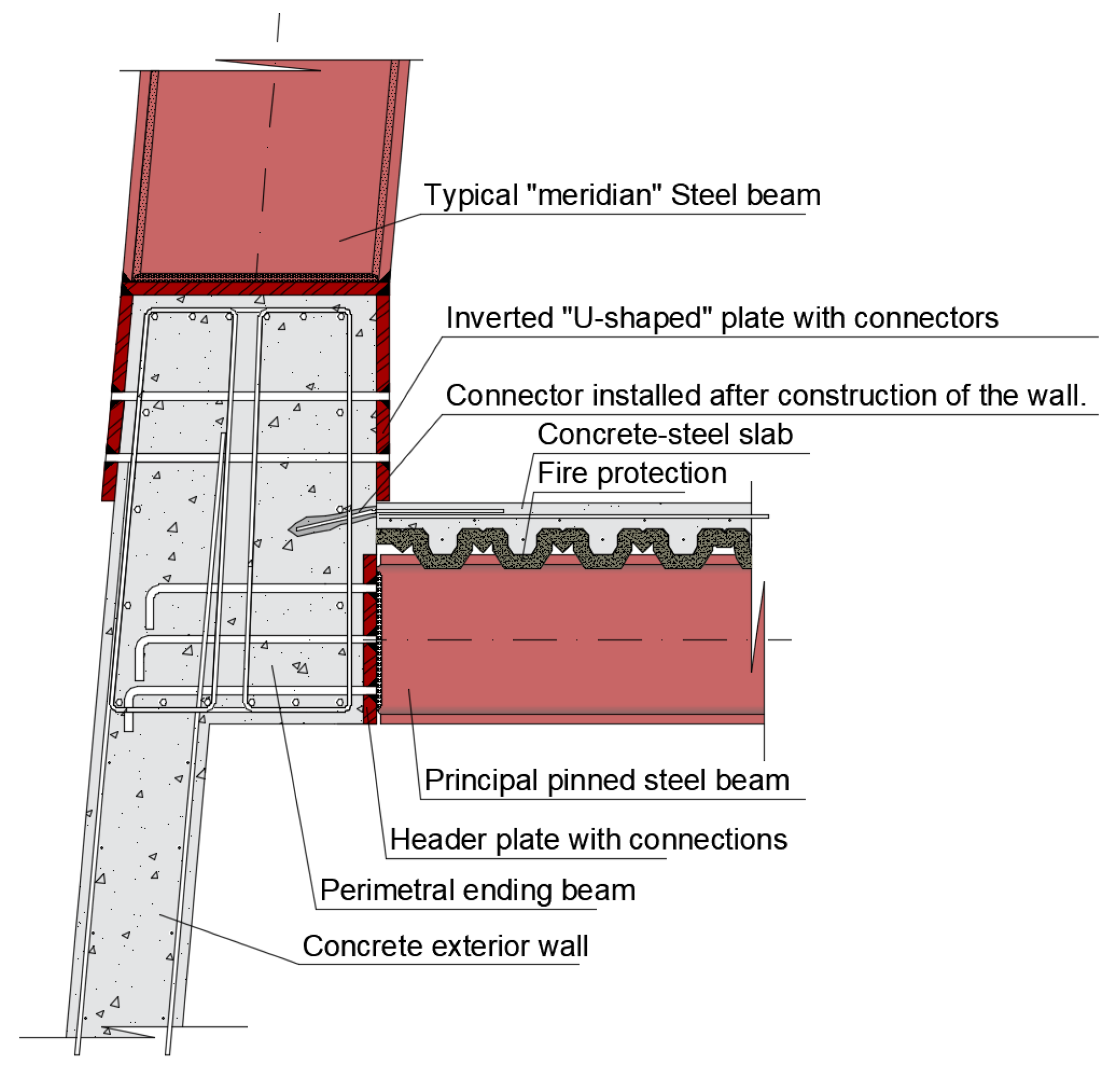
The support of the meridians (see
Figure 11) on the concrete wall was resolved using an inverted U-shaped profile with a base matching the thickness of the upper part of the wall, made of steel plates and bolts. This profile, embedded in the wall during the concreting process, ensured a clean joint. The meridians were welded onto these plates, thus eliminating the need for stiffeners. The horizontal forces were transferred through the wall and the top slab supported by the façade.
To optimize the construction process, it was suggested to conduct an assembly test of the entire structure on an empty plot, away from the building, following the construction of a temporary foundation, which would be demolished after the test was completed. This approach aimed to mitigate potential issues at over 110 m in height while allowing workers to gain practice in the assembly process. It is worth noting that the dome stands at nearly 30 m high, equivalent to a 10-story building without intermediate columns. Given that the joints were ultimately welded—due to the challenges of using a bolted joint with a front plate—this test was not performed, partly due to the cost of the operation. The expertise of the metal workshop ELTE (ELTEC, also referred to as ELTE or later ELFE, was a renowned workshop that completed prestigious projects, including the Fira de L’Hospitalet, the roof of the Liceu, one of the grandstands at the Montmeló F1 circuit, the dome of the Agbar Tower, and the structure of the Fórum 2004 building in Barcelona, among others), which was responsible for many high-profile metal works in Catalonia during that period, combined with the precision that BIM was beginning to enforce in the industry, helped minimize the challenges encountered during the construction phase.
The assembly system for the dome was proposed by the construction company
Dragados. (
Dragados was the construction company awarded the project. On 18 April 2002, while the project was already in progress,
Dragados was acquired by
Florentino Pérez and integrated into the
ACS group. The construction and technical teams were part of
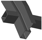
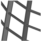
Dragados before the merger.) Pairs of meridians were raised, connected by their parallel bars, forming structures resembling ladders. These ladders were then linked together by welding the intermediate horizontal elements or tubes. Each ladder had a height roughly equivalent to two-thirds [
51] of the dome’s total height. In the final stage, a small structure containing a cross-shaped oculus was assembled on the ground, then hoisted into place by a crane and carefully fitted at both ends, completing the building’s enclosure.
Material execution price: EUR 1,000,000; construction period: 1.5 months.
7. Modal Analysis
Throughout the structure’s calculation, various checks were performed on each model, taking into account the fundamental buckling modes. Up to 100 buckling modes were generated for each case, although this number was not strictly required due to the structure’s highly regular nature.
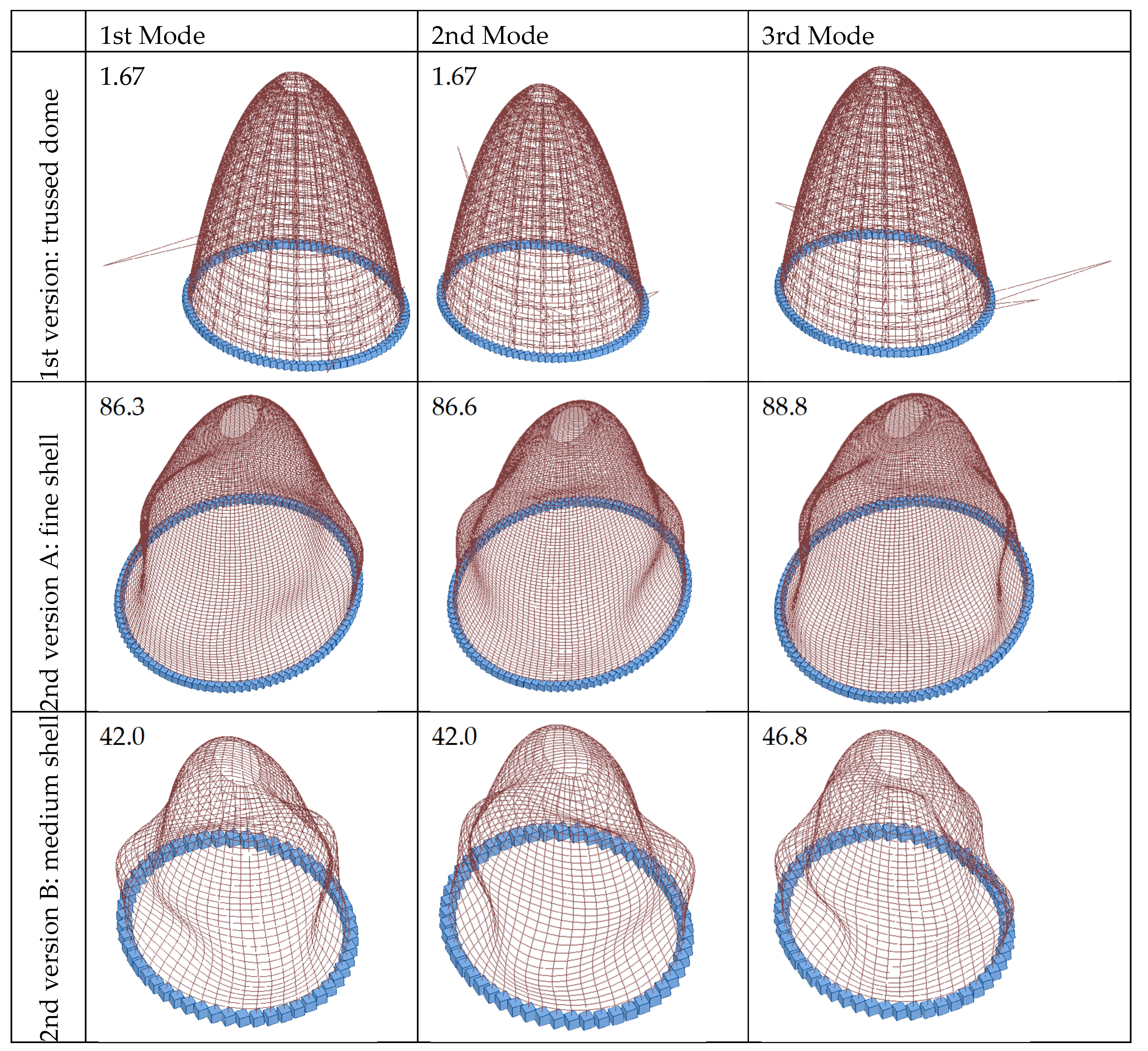
Figure 12 presents the first three modes in detail, which were used in a final comparison before finalizing the design.
The first version, which, as already mentioned, was not fully calculated, failed at the local level of a single bar, resulting in “progressive crushing.” The value of 1.67 indicates that the dome was not sufficiently stiffened to achieve a higher safety factor, as is the case with the other four versions.
The solution that worked best was undoubtedly 2A, because the bars were very short. The failure occurred due to excessive deformation of several parallel bars in its plane.
Despite this, it was a localized failure known as “wrinkling” of the surface. Something similar happened to Solution 2B, but since the bars were longer, the buckling safety factor was reduced to half that of the previous version, despite remaining a completely acceptable factor. Finally, versions 3 and 4 also present a defect, not a general one, which could be understood as one that presents the same deformation in each parallel, but rather, a “wrinkled” one, but in a broader way.
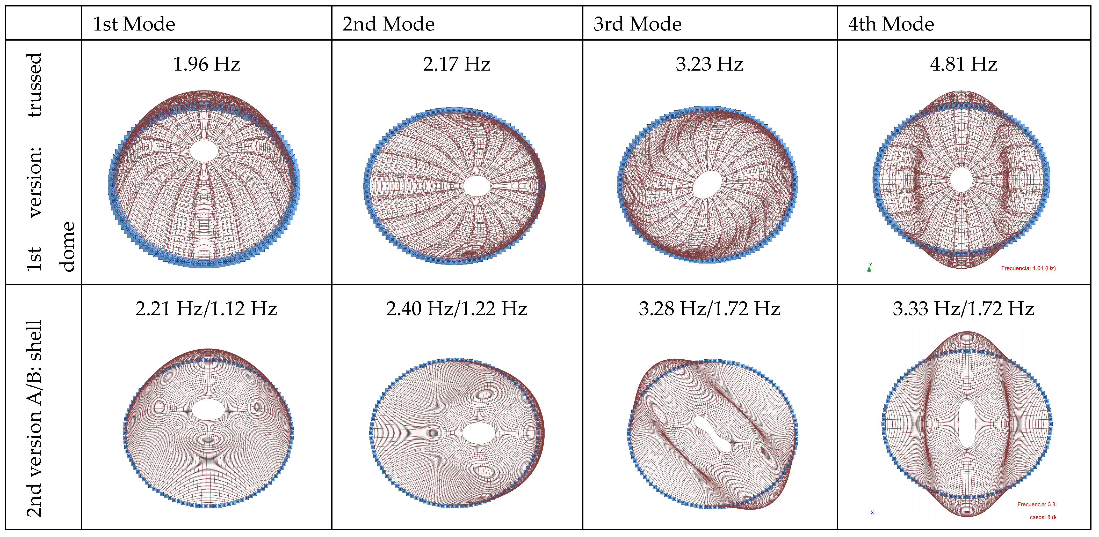
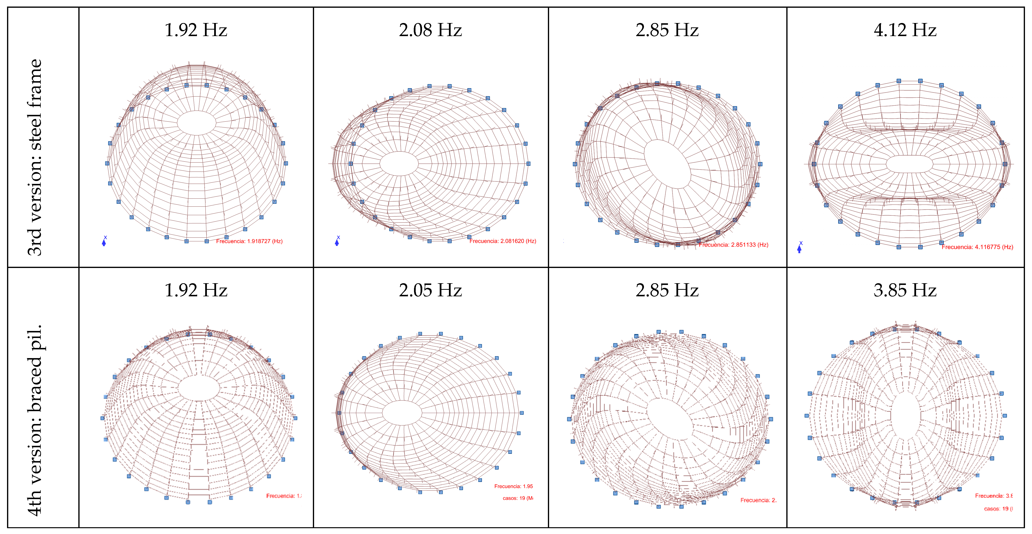
Although the earthquake case is not addressed in this document, with regard to the modal calculation, the frequencies detected in the first three versions are shown in
Figure 13.
The first two primary modes involved displacements along the two main axes, with the first mode, as expected, corresponding to displacement in a direction parallel to the shorter axis. The third mode was torsional, representing the rotation of the meridians in plan. In version 2, the frequencies were the highest among the models examined, with torsional deformation occurring in the fifth mode. This behavior is believed to be caused by the excess number of bars involved, even though it had the thinnest profile in plan. Mode four was characterized by the crushing of the oculus, along with the deformation of the meridians in their central section.
Modeling the supports at the base of each meridian as either a hinge or a fixed support influenced the deformation results and primary modes, with the fixed support providing a slightly more favorable response. The continuous lower wall, which supported the meridians, occasionally had windows beneath this level, making it necessary to consider the wall’s torsional behavior to resist the fixed moments.
8. Verification of Angular Distortion on the Glass and Deformation Analysis
The dome’s deformations were kept within limits to ensure the structure did not collide with the post-tensioned slabs. However, this was not the primary factor, as the slabs were sufficiently spaced to prevent such an effect. Instead, it was the stresses within the elements that ultimately determined the final section dimensions.
Once the dome’s calculations were completed, a concern arose regarding the suitability of the glass for the designed structure. Although deformation had been considered at all stages of the project and the glass was not of a large format, there was still a need to adapt to the manufacturer responsible for installing the cladding. One of the key concerns was whether the angular distortion of the trapezoidal glass panels could potentially cause them to break. Typically, glass can accommodate deformations effectively if one edge moves continuously away from the opposite edge in a direction perpendicular to its plane, as the edges function like a hinge. With proper clearance in the joints, there should be no risk of breakage. The glass can also endure elastic deformations at its central point, similar to how a beam behaves, up to a limit of L/250, as per the consultant’s guidelines, with the deformations considered in a direction perpendicular to the glass plane. However, the greatest risk to glass, aside from accidental impacts or corner damage, arises when one edge slides parallel to the plane of the glass in the opposite direction, creating tension along one diagonal and compression along the other. Since the glass is supported by two parallels and two meridians, this phenomenon could occur.
The need for this verification emerged during the construction phase and was developed by BOMA, with subsequent certification by civil engineer Francisco Quintero from Dragados, at a time when model 4 had not yet been finalized. Therefore, it was crucial to obtain results for each variant, automatically assessing every proposed change. Between two meridians, there are 17 trapezoids, with 26 spans and two diagonals per element, resulting in 882 diagonals, each with different calculation hypotheses. The only method provided by the calculation software for verification involved manually consolidating the data in a spreadsheet, comparing the deformations at the joints, subtracting them, measuring the diagonal, and then calculating the elongation in absolute terms. However, the program did not arrange the joints geometrically, making the process extremely slow. To expedite the process, fictitious bars were manually inserted into each trapezoid, corresponding to the positions of the two diagonals, within the program. Given the symmetry of the structure, it was sufficient to define only 25% of the diagonals and then apply two symmetry operations in the calculation program. The bars were defined using a material with a low elastic limit, specifically ceramic, and a small cross-section of φ4 mm. This configuration resulted in a model with stresses and deformations nearly identical to those of the previous one. This approach allowed us to determine the longitudinal deformation of each bar, effectively capturing the angular distortion. A clearer representation of these diagonals can be seen in
Figure 10.
The clearance in the joints ultimately imposed the final restriction: the maximum allowable angular distortion was limited to 2 mm, representing the maximum possible elongation or shortening of the diagonals. Despite this strict limit, the dome performed correctly under each scenario. Only two diagonals exceeded the maximum deformation, and after applying symmetries, this resulted in a total of two glass panels across the entire façade. This situation raised some questions; as all the meridian profiles were identical, it seemed that all profiles would need to be increased, thereby unnecessarily increasing the final total. The section was upgraded to the next profile in the catalog range, and while the angular distortion result remained nearly the same, the weight increase amounted to roughly 15% more.
The maximum deformation obtained in this case was 2.02 mm. Achieving this result had been a particularly complex process, and it appeared that the expected cost savings would not materialize. If the steel weight turned out to be nearly identical to that of the executive project, the final calculation would have been in vain. To address this issue, we revisited the deformations in the spreadsheet. Francisco Quintero, upon reviewing the result, found the solution: he pressed the button to remove decimals, and the value displayed in the cell was 2.0 mm. While it might seem like an obvious or even unconscious decision, the situation made it clear that a 0.02 mm excess, equating to just a 1% increase, was not enough to risk breaking a glass, especially when wind pressures possibly greater than those that might occur in the future had been considered along with regulatory safety coefficients and multiple hypotheses. Thus, disregarding a deformation imperceptible to the human eye could never be deemed an imprudent action. We had reached a level of such precision and attention to detail that it seemed every minor aspect needed to be resolved and numerically justified. When the machines’ responses end, human judgment must take over.
Another anecdote from the project is that, at one stage before entering the construction phase, there was consideration of using St. Andrew’s crosses as structural elements. Undoubtedly, these elements, with a certain degree of rigidity, could have reduced the final weight of the dome, but not radically, as the shape of the profiles had to be carefully evaluated alongside the necessary intumescent coating. It is worth mentioning that diagonals have a strong engineering component and reduce the visibility from the viewing platform, while their removal is more appealing from an architectural standpoint. In the end, both alternatives would have been equally acceptable after thorough design analysis.
9. Future Research Directions
The article focuses on solving a real case from an initial form. To this end, a significant amount of time was invested in researching enclosure and structural solutions. Therefore, we consider this a research document of great value to the reader. The work was conducted under the conditions of the early 21st century; therefore, it does not explore other more current lines of research, such as modifying the choice of material. The use of more current glue-laminated timber or precast concrete to improve performance and on-site assembly may also be a more current factor. Another aspect to be addressed may be the choice of enclosure, more in line with current laws, focused on reducing climate control.
In the future, a new design study could be drafted considering the possibility of extreme situations, for example, in areas prone to earthquakes or in adverse areas with high wind turbulence. In Barcelona, when the executive project was drafted, the current NCSE-02 regulation was not yet mandatory; it is even expected that the regulation will change soon in Barcelona to an even more restrictive analysis scenario than the current one. Despite the above, Barcelona currently works with a basic acceleration of 0.04 g, much lower than other architectures in the same country, and much lower than other regions, such as Japan or South America, where certain architectural solutions are inadvisable. We do not believe this factor is sufficient to discourage a shape like the one analyzed, but it may be a determining factor in redefining joints, sections, and, in general, the ductility of the structure.
On the other hand, wind may be a determining factor in the future, depending on the climate change the world is experiencing. Wind damage is becoming more frequent and severe in Catalonia. The shape of a dome is better suited to reducing the effects of wind than other shapes formed of planes and edges, or smoother shapes. As mentioned at the beginning, a thorough analysis of the joints was not performed from the perspective of the progressive collapse of the dome, a design concern that was taken more seriously once the building’s structure was completed.
Ultimately, the combination of extreme natural or human-made situations could be the subject of a future line of research.
10. Conclusions
This article describes the process of exploring the materiality of a building where both the structure and the enclosure play a fundamental role: a metal dome nearly 30 m high. The analysis was carried out based on a predefined volumetric form, the shape of which remained unchanged in the ten versions examined.
Table 2 summarizes the main results obtained in this process and is undoubtedly the most notable contribution of this article.
The process described begins with an analysis of the building’s requirements, including the design of the enclosure and perimeter maintenance platforms. It then progresses to defining the structural forces based on applicable current regulations. The final stage involves proposing multiple solutions, all maintaining the same external volumetric form while evolving and adapting at each iteration based on the knowledge gained from previous versions. This iterative design analysis is the most valuable contribution of this article, demonstrating how the final outcome emerges as a direct result of a structured form-finding process.
The first contribution drawn from this study consists of the proposal of multiple working forms of a dome—up to four—all maintaining the same external volumetric form. These forms evolve and adapt in each iteration based on the knowledge acquired in previous versions, recognizing problems, and providing solutions to the form.
The second contribution focuses on the pre-dimensioning of a pointed dome. In cases like the one described in this article, the consultant must develop their own approach to offer a precise and cost-effective solution for the client.
Table 2 illustrates that the meridians had a ratio of approximately H/50. To achieve higher ratios, i.e., to reduce profile thickness, it was necessary to place the profiles closer together, approximately 1 m apart.
The third contribution aimed to investigate the material quantities of the various models proposed in this paper. An approximate value of 100 kg/m
2 of S-355-J0 steel was obtained, using the square meters of the façade as a reference. A key aspect was the choice of structural type. However, the most decisive factor was undoubtedly the fire protection provided by the intumescent paint. Once the fire resistance requirement set by the fire department—although not excessively high at R-90—was established, its consideration in the calculations led to a 175% increase in the amount of steel required. However, by optimizing the node technology and adjusting the profiles, this increase was ultimately reduced to 138%. If the required fire resistance had been higher, a more precise calculation using CFD analysis would have been necessary. In 2002, numerical methods had not yet reached the level of accuracy, cost-effectiveness, or speed they offer today [
52]. On the contrary, if a façade-type element supported by slabs had been considered and the fire department had accepted a lower stability requirement, close to REI-30, the amount of material would have been reduced to just under half of that used in the final solution.
The fourth and final aspect of our investigation focuses on the analysis of buckling modes and modal calculation. In all cases, except the first, local creasing failure was observed. The exception was the first version, which was not fully calculated. Regarding the modal calculation, in all versions, the dome showed a mass participation close to 90%, indicating no signs of local failure. The frequency results for the first four modes were largely consistent across all versions, with the exception of the second version, which exhibited noticeably higher values. The divergence was due to the use of a shell-type solution with an excessive number of elements, which increased the complexity of the construction. The first two modes were always translational: the first parallel to the minor axis and the second along the major axis. The third mode corresponded to torsion, while the fourth involved crushing of both the oculus and the dome. Notably, the second version was the only one that improved torsional behavior, making torsion the fifth buckling mode in this case.


 ,
, 


