1. Introduction
In structures, the beam–column connection joint is a crucial part that plays a significant role in transmitting internal forces between beams and columns and coordinating deformations. They are subjected to complex loading conditions, including axial forces, bending moments, and shear forces from columns, as well as bending moments, shear forces, and torsional effects from beams [
1,
2,
3]. Additionally, factors such as shrinkage, creep, temperature variations, and foundation settlement can also influence the behavior of joints [
4,
5,
6]. Under seismic actions, joints are particularly vulnerable and prone to damage, and failure of joints can lead to the loss of load-carrying capacity of the entire frame and structural collapse [
7,
8,
9]. With the increase in the service life of buildings, changes in their functions, and the threat of various natural disasters, the beam–column connection joints of existing buildings often face various damages, weakening the load-bearing capacity and seismic performance of the joints. Therefore, strengthening and renovation work is urgently needed.
At present, there are many strengthening methods for beam–column connection joints, such as the enlarged cross-section method, the method of bonding fiber-reinforced polymer, and the method of bonding steel plate [
10,
11,
12,
13,
14,
15,
16,
17]. The enlarged cross-section method can improve the load-bearing capacity of the joints by increasing the area of concrete and steel bars, but it will increase the self-weight of the structure and affect the use of building space. The method of bonding FRP is easy to construct, lightweight and high-strength, and can effectively improve the seismic performance of the joints, but there are problems with the bonding durability with the base material. The method of bonding steel plates can significantly improve the shear and bending resistance of the joints, but additional treatments are required for fire and corrosion protection. These strengthening methods have their own advantages and disadvantages, and in practical engineering applications, a comprehensive selection needs to be made according to factors such as the failure mode of the joints, structural characteristics, and use requirements [
18,
19,
20].
Although existing research has achieved certain results in the strengthening of beam–column connection joints, they still need to be further improved. In view of this, conducting research on the strengthening of beam–column connection joints has important theoretical significance and engineering application value [
21,
22].
Taking the internal deep beam–column joints as the research objects, the study on the hysteretic performance of joints being strengthened with angle steel and bolts were conducted.
Considering the critical role of joints in frame structures and the need to ensure their satisfactory seismic performance, a new strengthening scheme for beam–column joints is proposed in this study. Angle steel is added at the beam–column joints, and the angle steel on both sides is fixed and clamped by bolts, so as to improve the mechanical performance of the joints, and also make the plastic hinge at the joints move outward, so as to protect the joints.
This approach can dissipate seismic energy and ensure the integrity of the bond between the beam reinforcement and concrete, which provides better confinement to the core region of the joint, enhancing its stiffness and shear strength, and thereby improving the seismic performance of the frame structure.
2. Testing Process
To verify the effectiveness of angle steel strengthened frame joints, relevant experimental studies were conducted.
2.1. Test Specimen
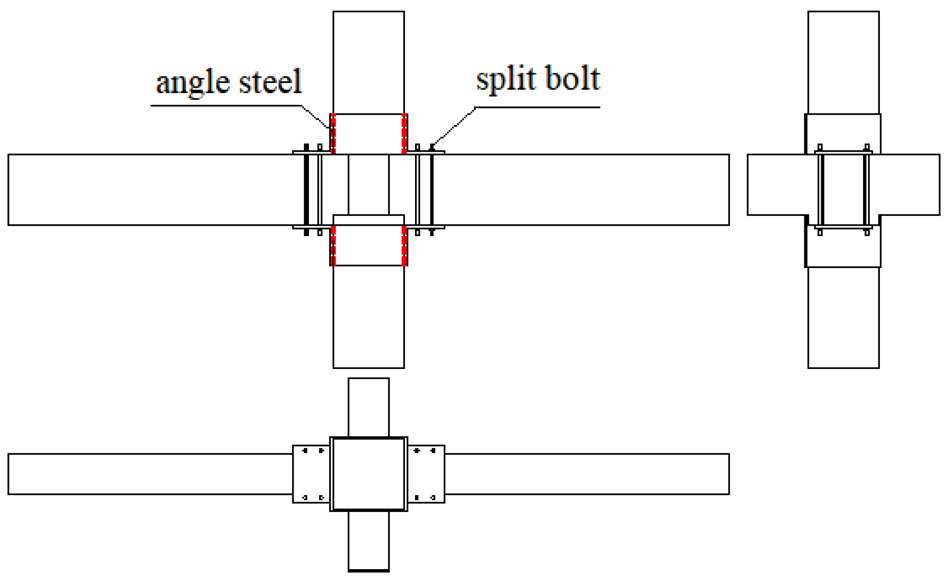
This experiment focuses on the intermediate joints of a general multi-story and multi-span frame under horizontal forces. The beam–column combination between the beam–column reverse bending points is selected as the specimen, and the specimen is shown in
Figure 1.
Angle steel is set at the beam–column joint and fixed by tension bolts. This method causes the plastic hinge at the end of the beam to move outward, improves the stress state of the joint, enhances its ductility, and improves the bending strength of the beam–column section, thereby reinforcing the beam–column joint.
Two specimens were made, one of which was strengthened with angle steel L200×20 at the beam–column node, numbered RJ-1. The other one is not strengthened as a comparison, numbered J-1. The concrete strength grade used is C30 with a compressive strength of 29.7 MPa, the longitudinal reinforcement of beams and columns is HRB400 ribbed steel bars with a yield strength of 437.5 MPa, and the stirrups of beams, columns, and nodes are HPB235 plain round steel bars with a yield strength of 302.5 MPa. The diameter of stirrup is 8 mm, and the stirrup spacing is 150 mm. The dimensions and reinforcement of the two specimens are identical, and the cross-section is shown in
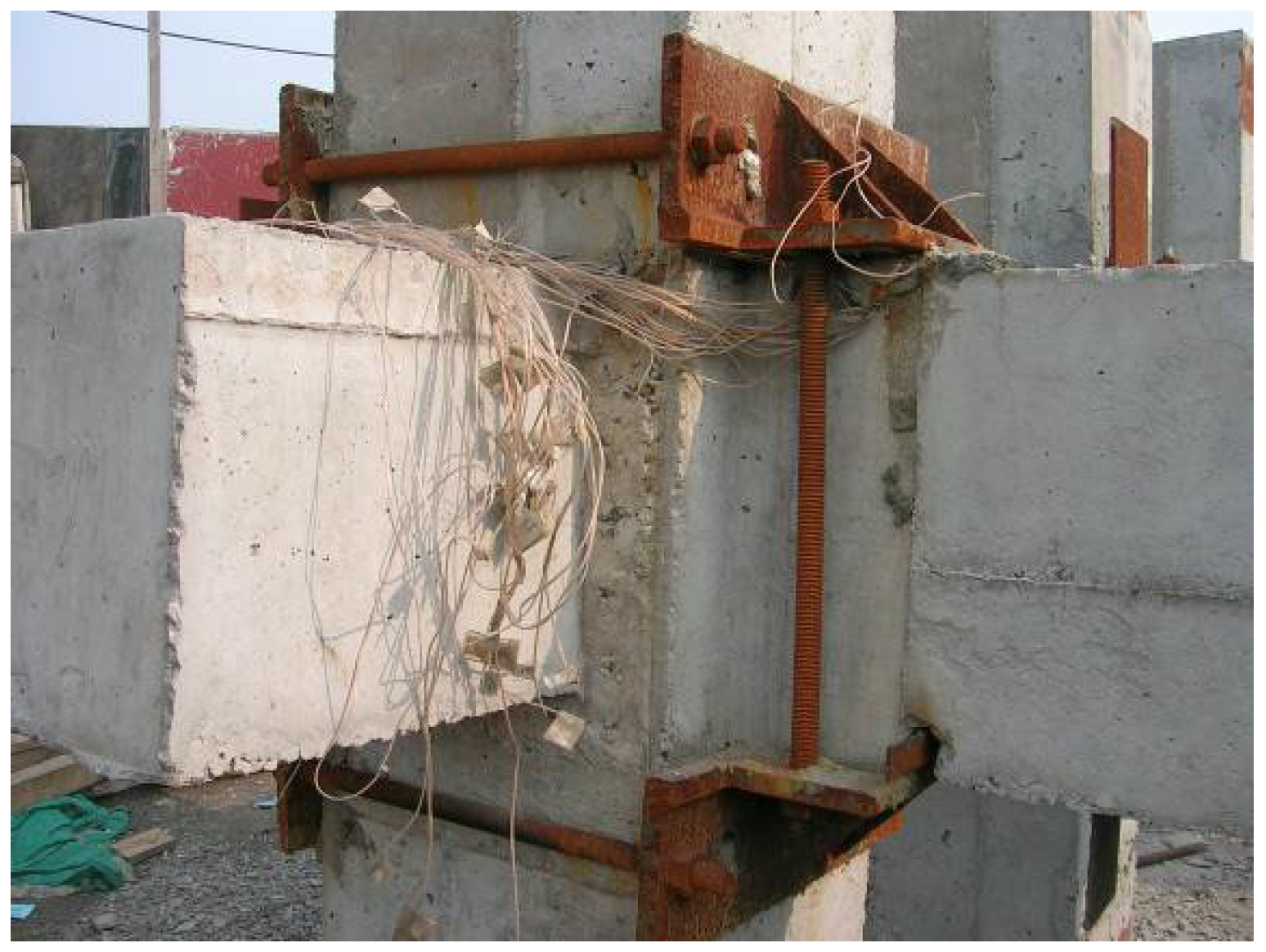
Figure 2. The experimental strengthened node is shown in
Figure 3.
2.2. Test Device
The loading device of the test is shown in
Figure 4. The 320 t hydraulic jack is installed at the upper end of the column to apply axial pressure to the node. Two sets of jacks with the same specifications are arranged at the outer ends of the left and right beams and controlled by an oil pump to achieve synchronous low cycle repeated loading. Steel plate cushion blocks are pre-set at the upper and lower ends of the column and on both sides, and four steel blocks welded with circular steel bars are used to clamp the column head on both sides of the column end, simulating the hinge support of the column end.
The loading method adopts a mixed control of load and displacement. Firstly, the hydraulic jack at the upper column end applies axial force to the specimen to a predetermined axial compression ratio. Subsequently, a low-cycle repeated load is applied by using two jacks at the outer ends of the beams, one upwards and the other downwards, in a symmetrical manner.
At the initial stage of loading, the load is controlled by a graded cyclic loading. When the beam end reaches yield, the loading is controlled by displacement. The multiple of the displacement at the yield of the beam end is taken to load step by step, and the cycle is repeated three times for each displacement value.
3. Analysis of Test Results
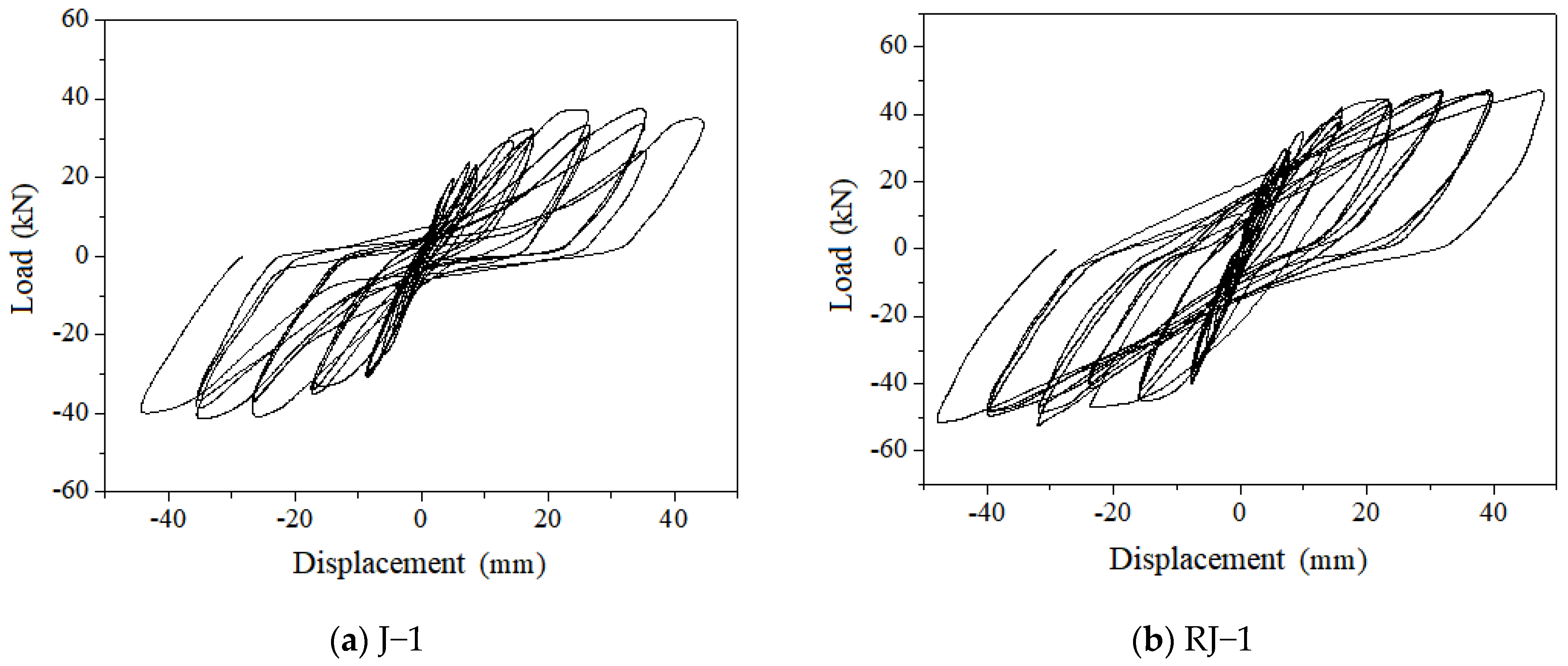
The load-displacement curves at the beam end of two specimens J-1 and RJ-1 obtained from the test results are shown in
Figure 5.
The comparison specimen J-1 maintains good linear elasticity at the beginning of loading, without residual deformation, and has very low energy dissipation capacity. When loaded to 9 mm (30 kN), the hysteresis curve forms a full hysteresis loop. However, at 18 mm (33 kN), the hysteresis curve began to experience “necking” phenomenon, and this phenomenon became more pronounced as the displacement of the beam end increased. When the displacement increases to 36 mm (38 kN), the hysteresis curve shows a horizontal segment during loading, indicating almost zero stiffness. Finally, the hysteresis curve shows an inverted S-shape and gradually reverses towards the displacement axis, resulting in a decreasing initial stiffness under loading.
At the beginning of loading, the specimen RJ-1 maintained good linear elasticity, with almost no residual deformation and minimal energy dissipation capacity. A full hysteresis loop is formed on the 8 mm (35 kN), and as the displacement increases, the hysteresis loop becomes fuller until the end of loading, and there is no necking phenomenon on the curve.
Through comparative tests of angle steel strengthened beam–column nodes, it can be concluded that the beam reinforcement in the strengthened specimen nodes is effectively protected, the anchoring length increases, and the bonding performance of the beam reinforcement is strengthened. At the same time, strengthening causes the plastic hinge to move outward, avoiding cracks at the beam–column interface, achieving continuous constraints on the nodes by the beam, improving the seismic performance of the node combination, and exhibiting a full hysteresis loop in the hysteresis curve. Illustrating that the angle steel strengthening scheme proposed in this paper can significantly improve the seismic performance of beam–column joints.
4. Finite Element Modeling
The finite element model is established by ABAQUS based on the experimental conditions conducted by the authors. The concrete has a strength grade of C30, while the longitudinal reinforcement for beams and columns consists of HRB400 steel bars. The stirrups for beams, columns, and joints are made of HPB235 steel bars. The angle steel used for joint strengthening is L200×20. The material properties are set according to the previous experiment. Axial compression is applied at the upper end of the column, while axial tension or compression is applied at the outer end of the beam, allowing for synchronized low-cycle cyclic loading [
23,
24].
4.1. Mesh of the FEA Model
The concrete elements have a side length of 50 mm, with a local refinement of 25 mm in the joint region, resulting in a total of 6196 elements. The reinforcement elements have a side length of 25 mm, and a total of 2992 elements are used. The side length of the strengthened angle steel is determined based on the thickness of the angle steel legs, and the mesh is approximately divided into hexahedral elements.
4.2. Element Selection
The finite element model of the strengthened concrete joint adopts a segregated approach, including three types of elements: concrete, reinforcement, and angle steel [
25]. The concrete and angle steel are represented using three-dimensional solid elements (C3D8R), while the reinforcement is modeled using three-node truss elements (T3D2) in three-dimensional space [
26].
Using the truss element approach, the connection between concrete and reinforcement is established by creating separate models for concrete and reinforcement (longitudinal and stirrup reinforcement) within their respective parts [
27]. The sections and properties are assigned in the property section, and the interaction section uses the “embed” feature to embed the reinforcement skeleton into the solid concrete model, thus achieving the connection between concrete and reinforcement [
28]. The truss elements do not need to have the same mesh as the solid elements, their nodes are automatically constrained to the nodes of the solid elements. ABAQUS assumes that the behavior of concrete is independent of the surrounding bonded reinforcement. The interaction effects, such as bond-slip, between concrete and reinforcement are approximated by introducing “tension stiffening” in the concrete model [
29].
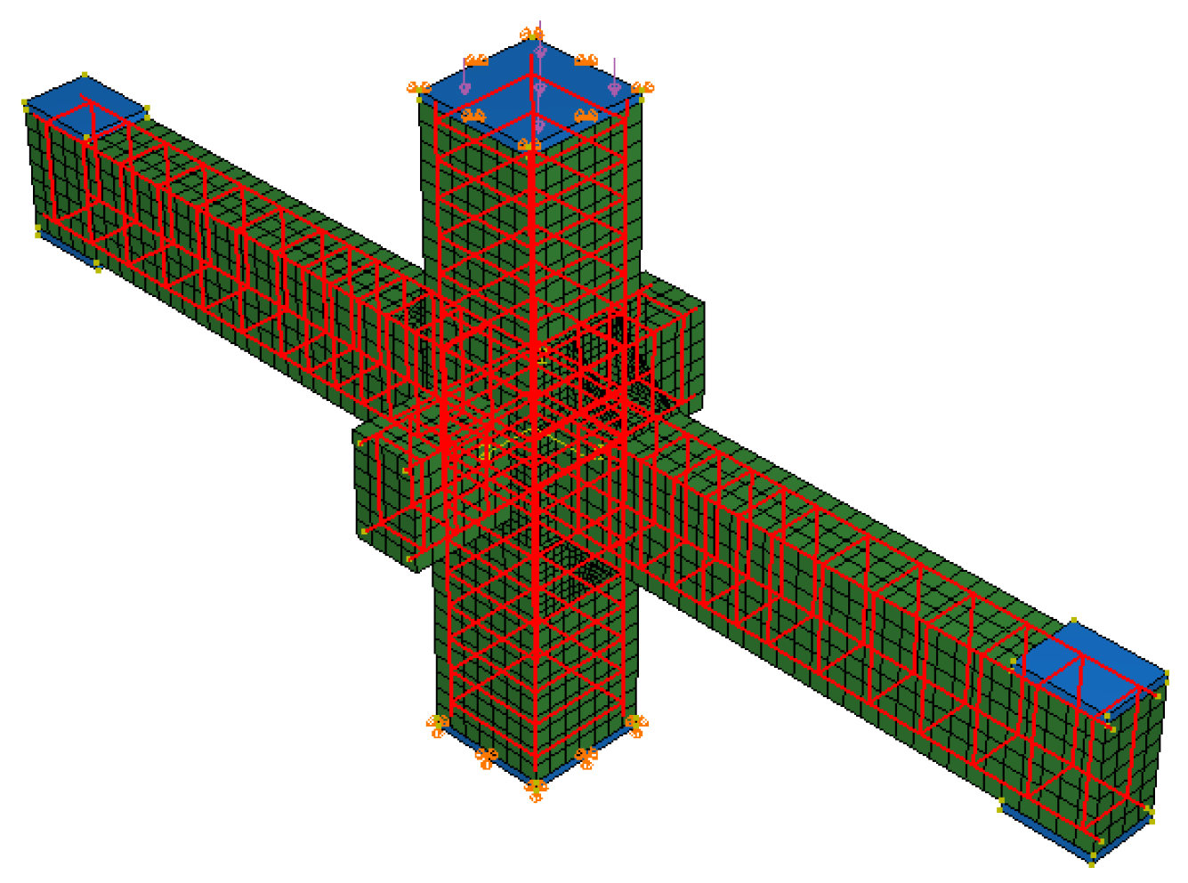
In the simulation of the strengthened concrete joint, rigid elements are added at the top and bottom surfaces of the column and the upper and lower surfaces of the beam ends, forming rigid faces to simulate the test loading pad. The computational model is illustrated in
Figure 6.
4.3. Material Model
In the finite element simulation, the damaged plasticity model is adopted for a constitutive model of concrete. The damage index is introduced to simulate the characteristic that the unloading stiffness of concrete decreases with the increase in damage by reducing the elastic stiffness matrix of concrete. Based on the damaged plasticity model of concrete, the formation of the yield surface is mainly controlled by equivalent plastic strain.
The equivalent plastic strain of the model is calculated, which is the cumulative result of the plastic strain in the whole deformation process of the model. The equivalent plastic strain greater than 0 indicates that the material has yielded. In the finite element analysis model, concrete cracking is considered based on the fracture energy cracking criterion, which is defined by the calculation of cracking strain.
The plastic deformation of steel is described by Mises yield surface and the associated flow rule.
4.4. Loading Method
To accurately simulate the loading process of the test, the following boundary conditions can be applied to the model based on the test setup: horizontal displacement constraints in two directions at the top of the column, and horizontal and vertical displacement constraints in three directions at the bottom of the column [
30].
The loading is performed using displacement control. Initially, a vertical axial force is applied at the top of the column, followed by displacement loading applied at the left and right ends of the beam. The displacement increment for each step is 5 mm, and multiple sub-steps are used to achieve complete displacement.
4.5. Verification of Model Effectiveness
The finite element analysis data are compared with the test results conducted by the authors to validate the effectiveness of the finite element model and analysis method. Displacement loading is employed, and to facilitate comparison with the test results, the displacement is controlled to be equal to the experimental yield displacement. The loading process is divided into 12 steps to complete the entire process.
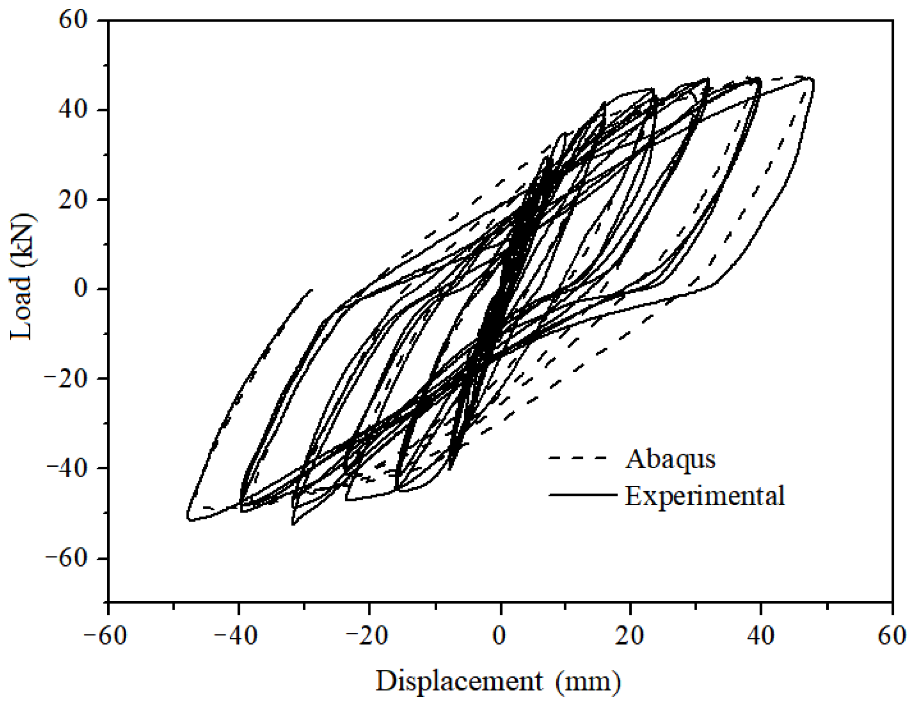
The comparison between the simulated specimen’s hysteresis curve and the experimental specimen’s hysteresis curve is shown in
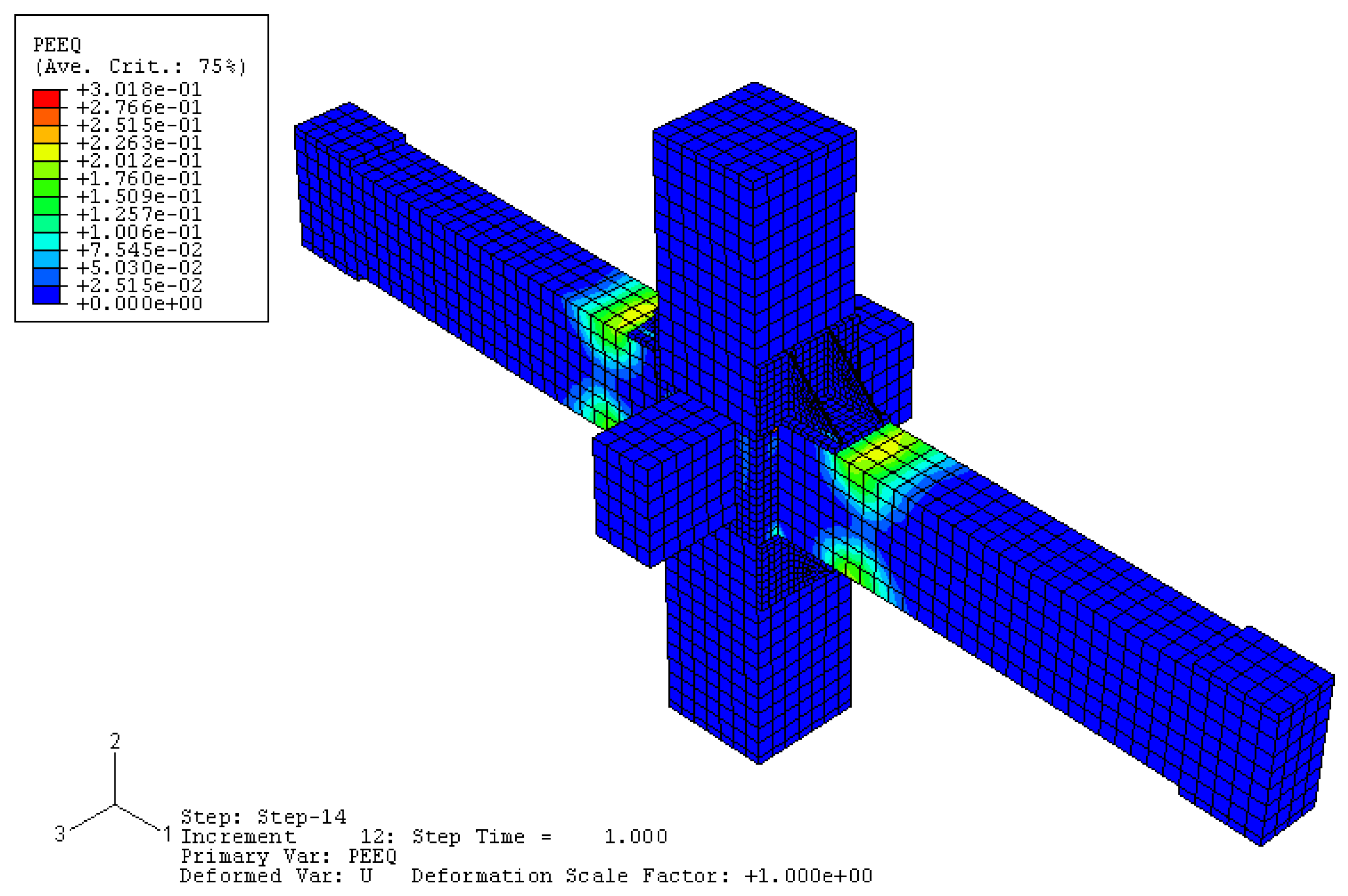
Figure 7, indicating a good agreement between the two. The equivalent plastic strain (PEEQ) of the simulated specimen, which represents the cumulative plastic strain throughout the deformation process [
31], is shown in
Figure 8. A PEEQ value greater than 0 indicates material yielding, which corresponds well with the actual failure mode of the experimental specimen.
Therefore, the analytical model used in this study can effectively simulate the ultimate bearing capacity and failure process of strengthened concrete nodes with angle steel strengthening. It is also observed that the plastic hinges of the beams are effectively shifted outward with the angle steel strengthening, leading to an improvement in the seismic performance of the nodes.
5. Numerical Analysis of Influencing Parameters
5.1. Influencing Parameters
To comprehensively study the improvement in the structural performance of existing strengthened concrete nodes with angle steel strengthening, the previously established computational model is used to analyze the parameters that affect the strengthening effect [
32]. These parameters include concrete strength grade, axial compression ratio, stirrup characteristic values, angle steel leg length, angle steel leg thickness, as well as the analysis of a group of spatial joints. Except for the concrete strength grade, the form, dimensions, and materials of the nodes in the analysis are consistent with the experiments described in this paper. The mechanical properties of the concrete are presented in
Table 1. The loading regime of the specimens adopts displacement control with Δ = 5 mm, and it is completed in 12 substeps. The strengthened angle steel without ribs is analyzed, and the detailed parameters of the calculated specimens are shown in
Table 2, totaling 39 components.
5.2. Concrete Strength Grade
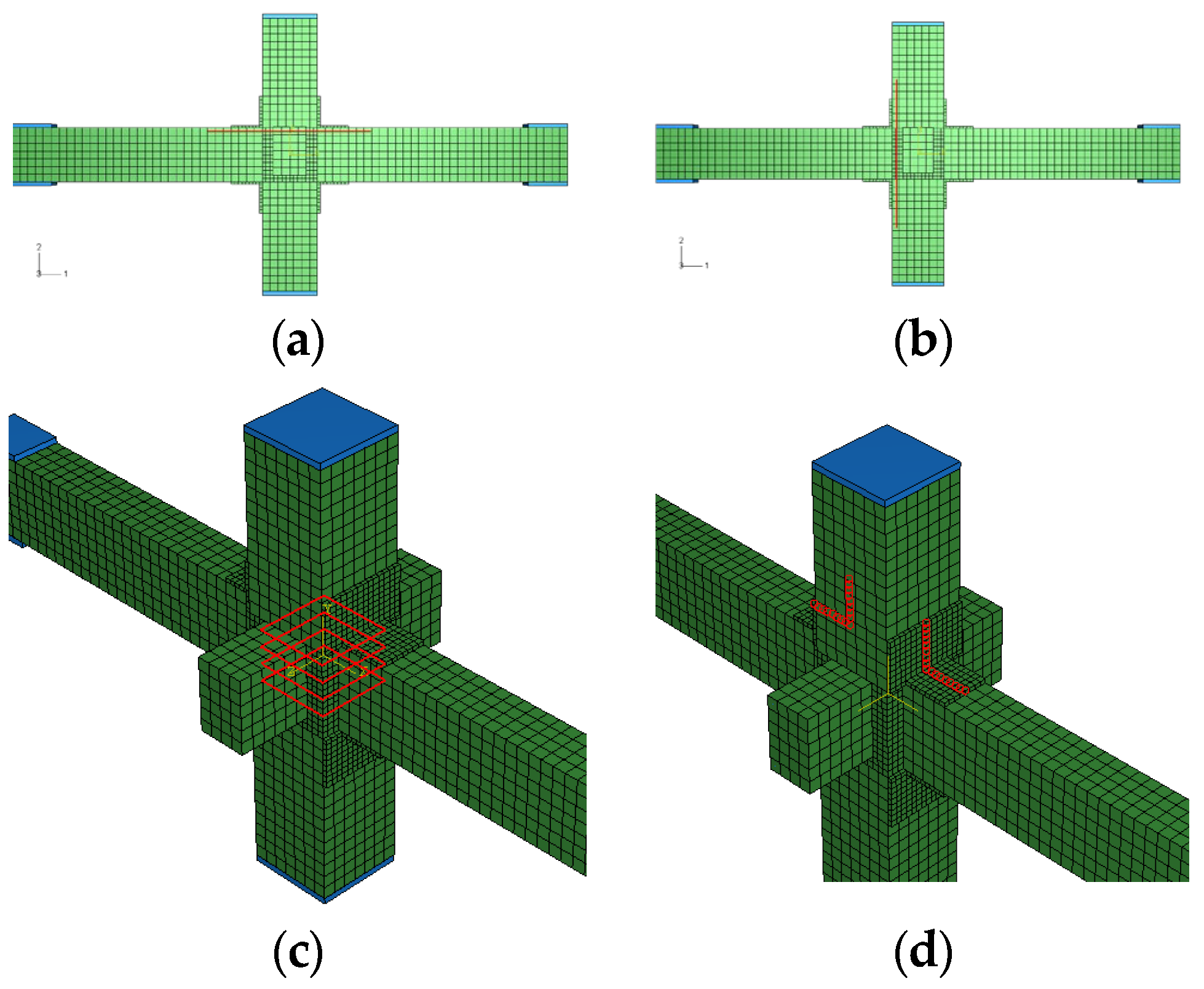
Under external loads, the node is subjected to various forces, and a portion of these forces is transmitted to the core region of the node through the longitudinal reinforcement of the beam and column in the form of bonding stress. The stirrup reinforcement within the node, together with the core concrete, bears these actions. Therefore, to study the changes in the performance of the node before and after strengthening, it is necessary to locate and analyze the stress–strain of the longitudinal reinforcement of the beam and column, the stirrup reinforcement within the node, and the strengthened angle steel throughout the entire loading process. The locations are shown in
Figure 9.
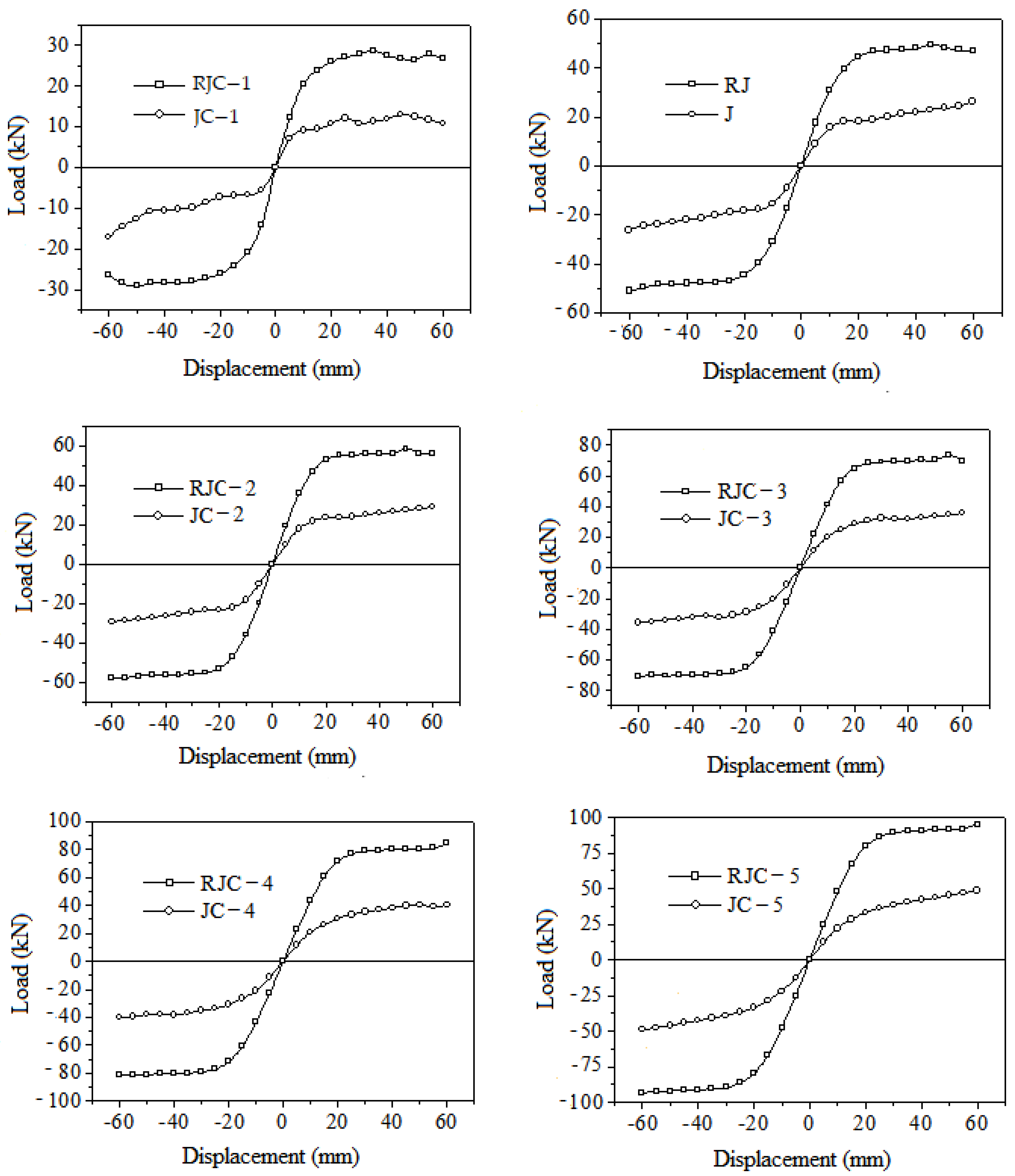
The skeleton curves of nodes with different concrete strength grades are shown in
Figure 10. The node assemblies basically go through three stages: elastic, yield, and ultimate under low-cycle repeated loading. By comparing the curves, it can be observed that the yield load and ultimate load of the strengthened components have significantly increased. This indicates that the angle steel can simultaneously enhance the strength and stiffness of the strengthened section, leading to a change in the failure mode of the joint, forcing the failure to occur externally and protecting the core region of the node, thus improving the ductility of the assembly. However, for the strengthened components with lower concrete strength, their bearing capacity shows a significant decrease in the later stages of loading. This obviously cannot meet the requirements of the node for ductile seismic performance, which involves dissipating seismic input energy through stable plastic deformation of secondary components while ensuring the structural load-bearing capacity and stiffness without degradation. Therefore, for nodes with lower early strength, it is necessary to strengthen the surrounding beams and columns simultaneously. The ultimate loads of these six components are shown in
Figure 10, and it can be observed that the bearing capacity of the strengthened components increases as the concrete strength grade increases. Furthermore, it can be seen that the increase in the bearing capacity of the strengthened components is more pronounced with higher concrete strength due to the displacement of beam plastic hinges outward.
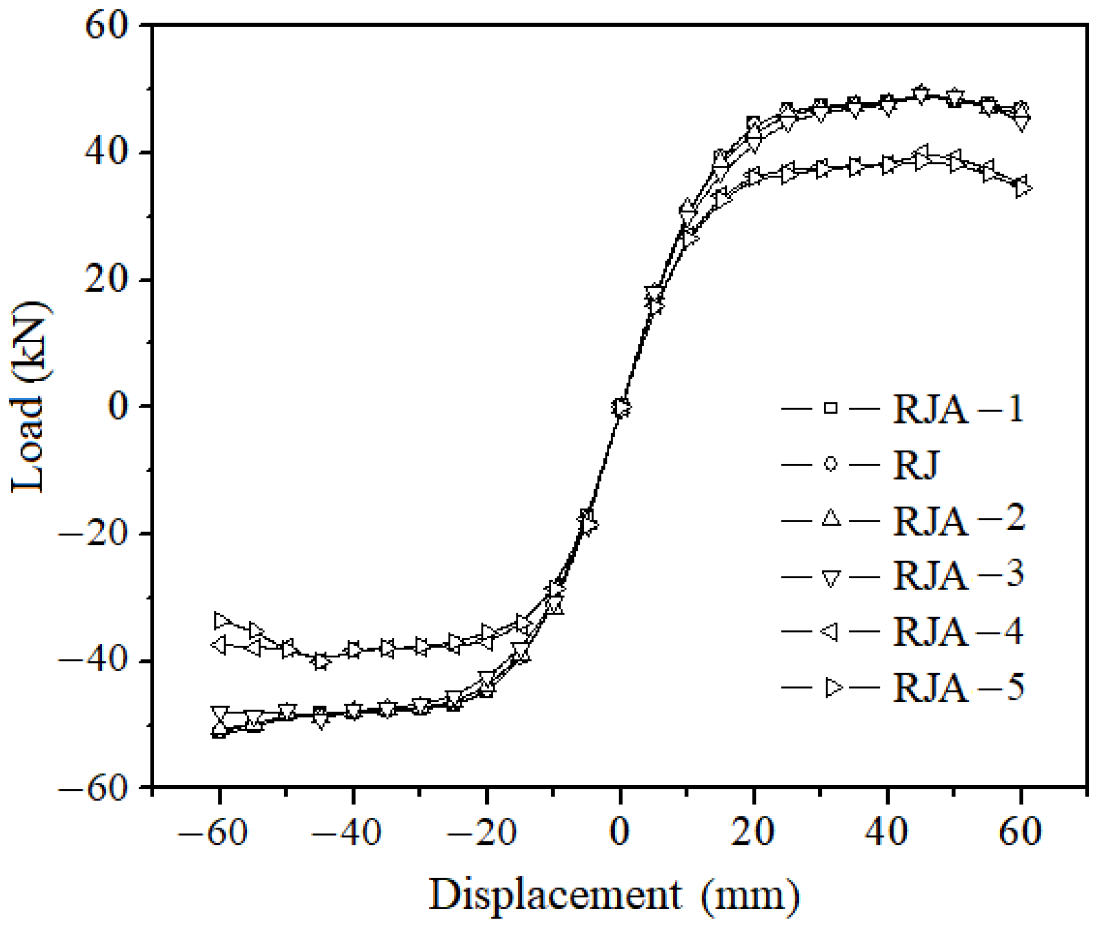
5.3. The Axial Compression Ratio
The axial compression ratio is the factor that has the greatest disagreement among researchers regarding its impact on the structural performance of nodes. This is because the influence of the axial compression ratio varies depending on the different failure modes of nodes. Generally, an appropriate axial compression ratio can limit the development of cracks in the core region of the node and increase the bonding performance of the longitudinal reinforcement passing through the core region. However, a high axial compression ratio will increase the compressive stress in the inclined strut, leading to diagonal compression failure. Therefore, it is necessary to analyze the structural performance of strengthened components under different axial compression ratios.
The skeleton curves of nodes with different axial compression ratios are shown in
Figure 11. It can be observed that the strengthened components do not exhibit a significant decrease in bearing capacity throughout the loading process, indicating that the strengthened components meet the requirements for seismic ductility. When the axial compression ratio is less than 0.6, the skeleton curves essentially overlap. However, when the axial compression ratio exceeds 0.6, the bearing capacity of the strengthened components significantly decreases. This phenomenon occurs because although an increased axial compression ratio causes an increase in compressive stress in the core region of the node, the strengthened angle steel also causes the compressive stress to shift towards the end of the angle steel, and the inclined strut enters the surrounding beams and columns, increasing in volume. Therefore, the strengthened angle steel can still make the plastic hinge move outward, so as to protect the joint. As the axial compression ratio continues to increase, the compressive stress in the core region gradually reaches the ultimate compressive stress of concrete. Eventually, concrete crushing occurs at the location of maximum compressive stress, resulting in the coexistence of beam plastic hinges and local node diagonal compression failure. The stiffness of the node deteriorates, and the bearing capacity decreases. Therefore, for components with high axial compression ratios, it is necessary to appropriately increase the reinforcement to withstand the higher compressive stress generated in the core region.
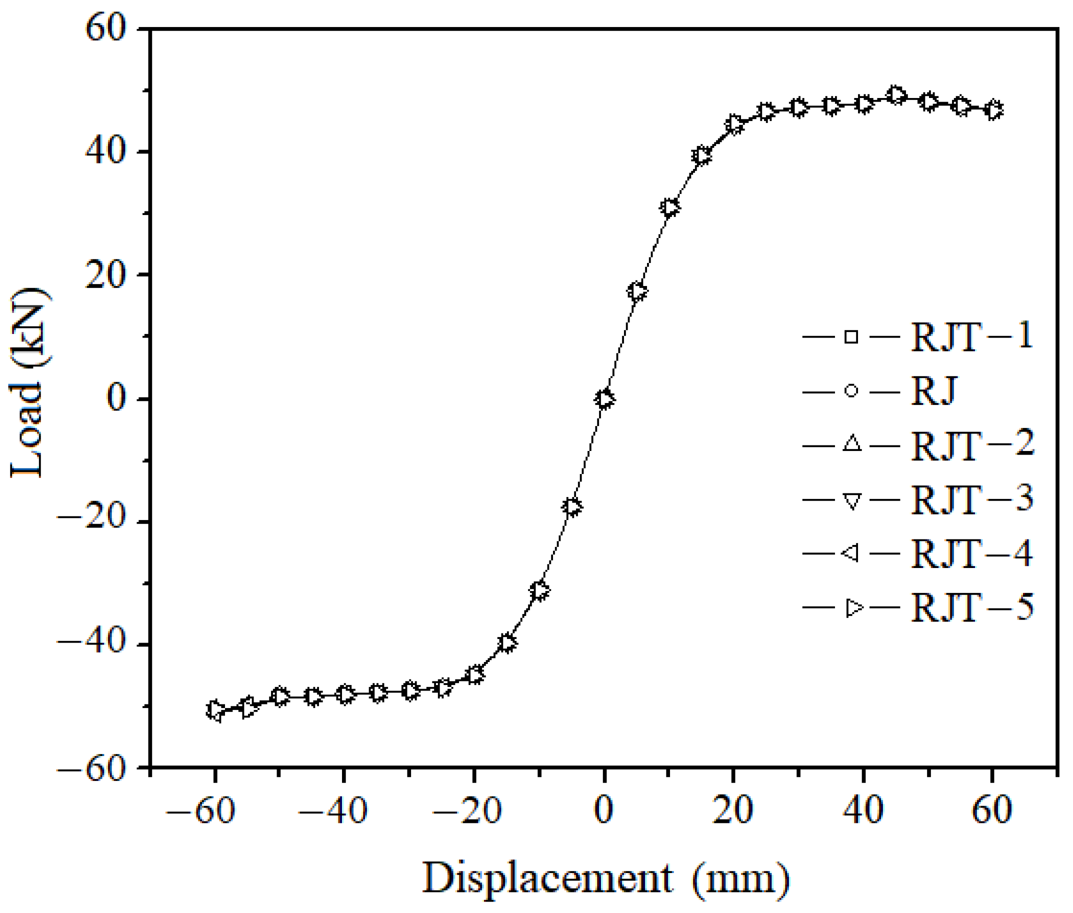
5.4. Stirrup Ratio
The use of horizontal closed stirrups is widely recognized as the most common method to improve the shear strength of nodes. This is because the stirrups placed inside the node not only confine the core concrete of the node, increasing its ability to transfer axial loads, but also resist the horizontal shear in the truss mechanism, thereby enhancing the shear carrying capacity of the node. However, when the stirrup ratio is too high, the node may still experience shear failure and the stirrups may not fully play their role, resulting in a lower shear strength than the calculated theoretical value, which is unsafe. Therefore, in the process of reinforcing nodes, it is necessary to consider not only low-stirrup cases but also high-stirrup cases preventing premature diagonal compression failure in the core region of nodes.
The skeleton curves of nodes with different stirrup ratios are shown in
Figure 12. It can be observed that the skeleton curves of the six different stirrup ratio cases are almost coincidental, indicating that the stirrup ratio has little influence on the strengthened nodes. This is because the angle steel plays a major role throughout the loading process, providing good protection to the strengthened concrete section, increasing the anchorage length of the longitudinal reinforcement passing through the core region, reducing the bond stress in the rebar, and weakening the truss mechanism. Moreover, the angle steel surrounding the node significantly improves its overall stiffness, minimizing the impact of increased stirrup quantities on the strengthened nodes. Therefore, it can be concluded that the strengthening method effectively solves the problem of configuring stirrups in the core region of joints.
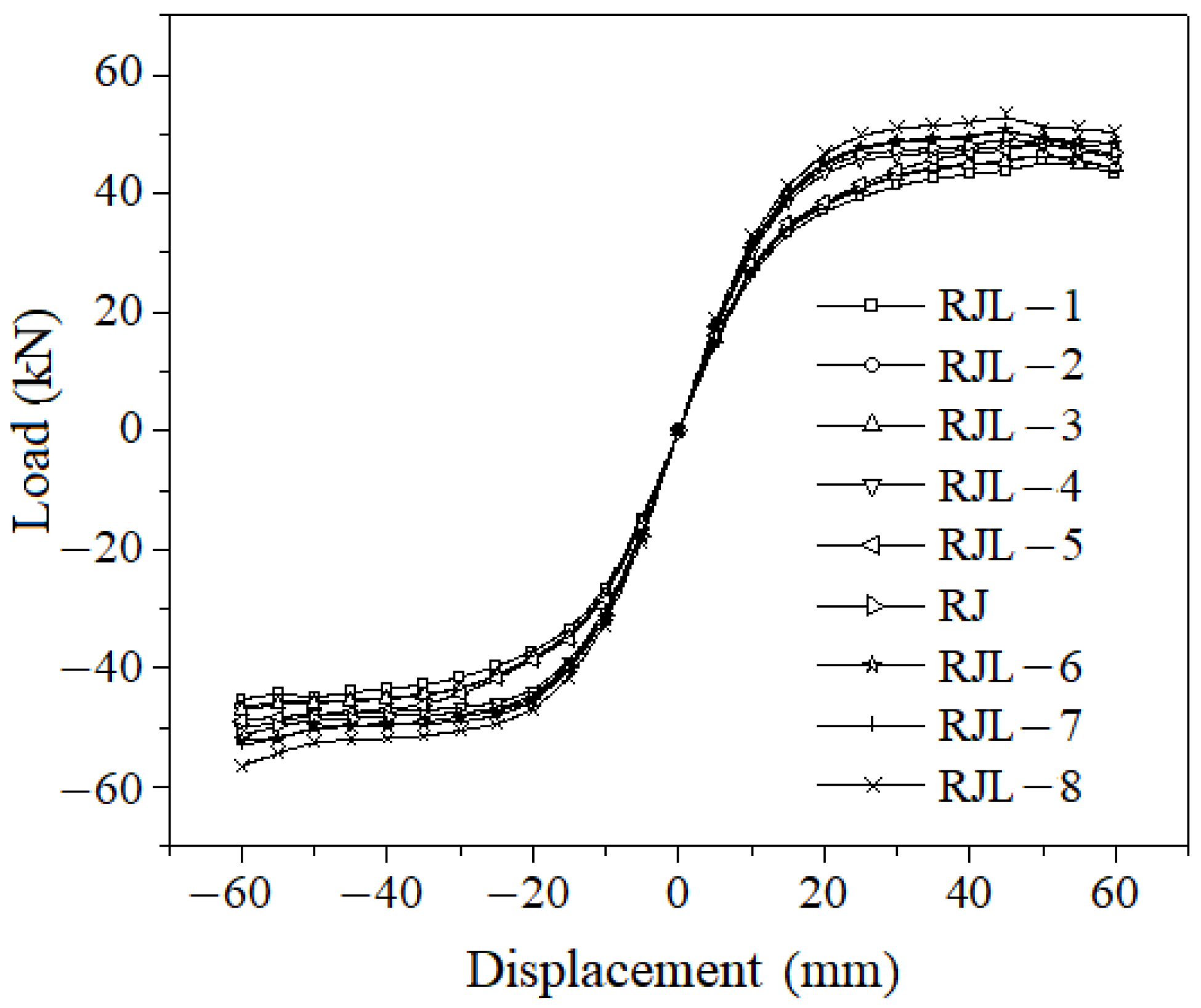
5.5. Angle Steel Leg Length
Based on experimental measurements, the range of plastic hinge extension in the node is generally within 1.0 to 1.5 times the beam height from the column edge. Therefore, the length of the angle steel leg should be within this range. The skeleton curves of nodes with different leg lengths are shown in
Figure 13. It can be observed that the strengthened components do not exhibit a significant decrease in load-carrying capacity throughout the loading process. This indicates that the slippage problem of the beam reinforcement has been effectively resolved, allowing the beam to continue to provide restraint to the core region of the node, thereby improving the shear strength of the node and enhancing its energy dissipation capacity.
As the leg length increases, the range covered by the skeleton curve gradually increases. When the leg length exceeds 180 mm (approximately 0.5 times the beam height), the skeleton curve shows significant growth. Afterward, the growth tends to be slower. This is because, initially, when the leg length is shorter, although the primary failure of the strengthened component occurs on the outside of the angle steel, cracks still extend to the column face, and even into the core region of the node, as demonstrated by the test results of specimen RJ-5. Furthermore, with a shorter reinforcement segment, the deformation of the plastic hinge region still concentrates near the column face, causing deformation in the node. These factors weaken the seismic performance of the strengthened component. Therefore, when selecting the size of the angle steel, the leg length should be ensured to be within the range of 0.5 hb to hb (where hb is the beam height).
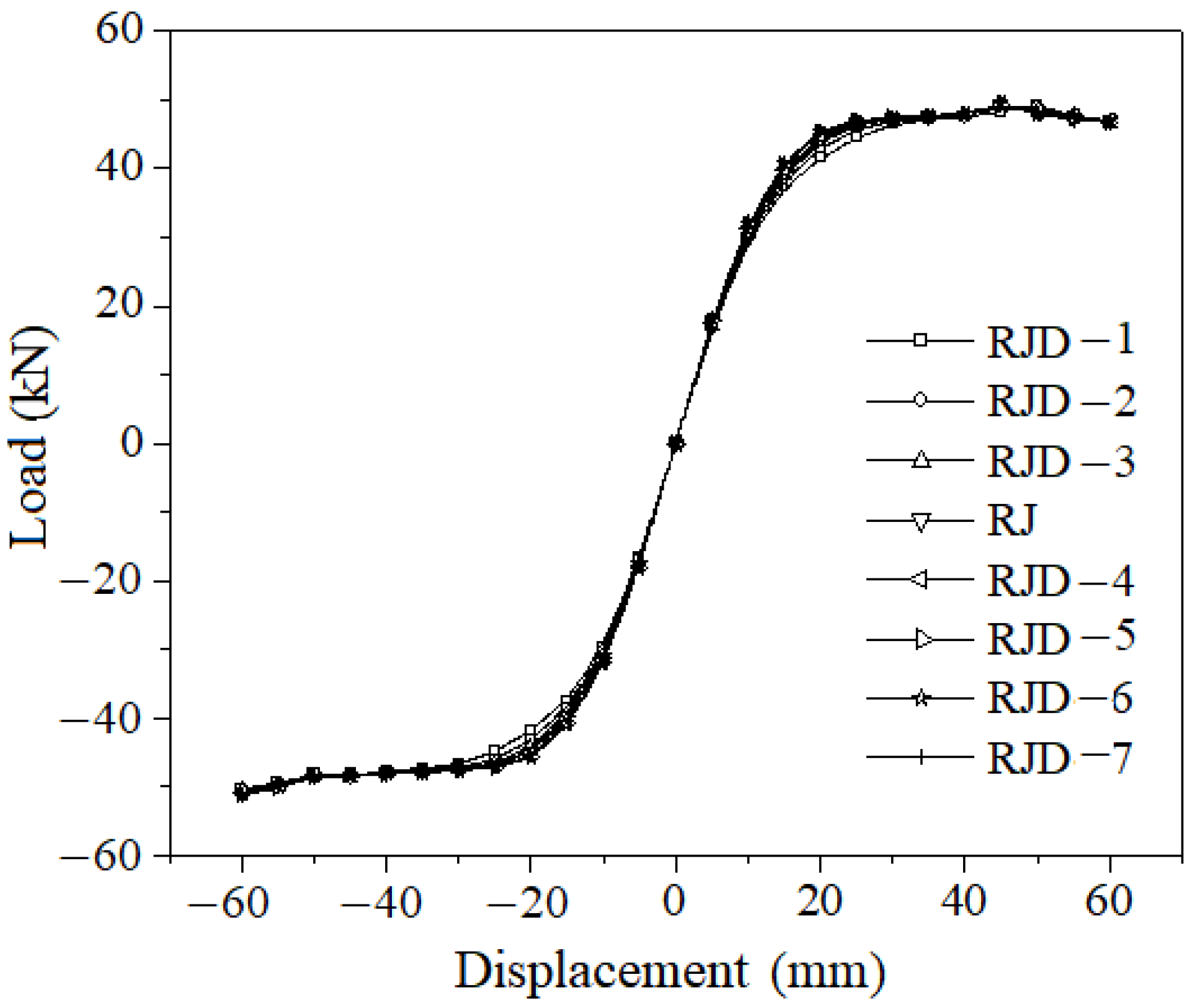
5.6. Angle Steel Leg Thickness
In order to achieve plastic hinge displacement, the bending strength of the beam section at the column face must be at least 1.25 times higher than the expected bending strength at the beam hinge. Therefore, the selected cross-section of the angle steel should meet the strength ratio of the beam section. To ensure the bond performance of the beam reinforcement, the width of the angle steel section should not be smaller than the beam width, making the thickness of the angle steel leg to be a controlling factor. The skeleton curves of nodes with different angle steel leg thicknesses are shown in
Figure 14. It can be observed that the selected angle steel leg thicknesses all meet the requirements and achieve plastic hinge displacement. However, increasing the leg thickness beyond the strength ratio for plastic hinge displacement only slightly improves the yield load and has little effect on other aspects. Therefore, the angle steel thickness can be appropriately increased on the basis of meeting the strength ratio to delay the strengthened component from entering the yielding stage.
5.7. Spatial Joints
In reality, the frames that bear loads are typically spatial frameworks (most nodes have two beams perpendicular to each other) and are equipped with floor slabs. Due to the randomness of seismic actions, most of the time there is an angle between the action and the building’s axis. When subjected to forces in two directions simultaneously, the beams of the frame may yield in both directions, resulting in plastic hinges. After the reinforcement bars yield and enter the node, the level of constraint on the node significantly decreases, leading to increased cracking and deformation, and degradation of the seismic performance. Therefore, it is necessary to analyze the stress conditions of the spatial frame nodes before and after strengthening.
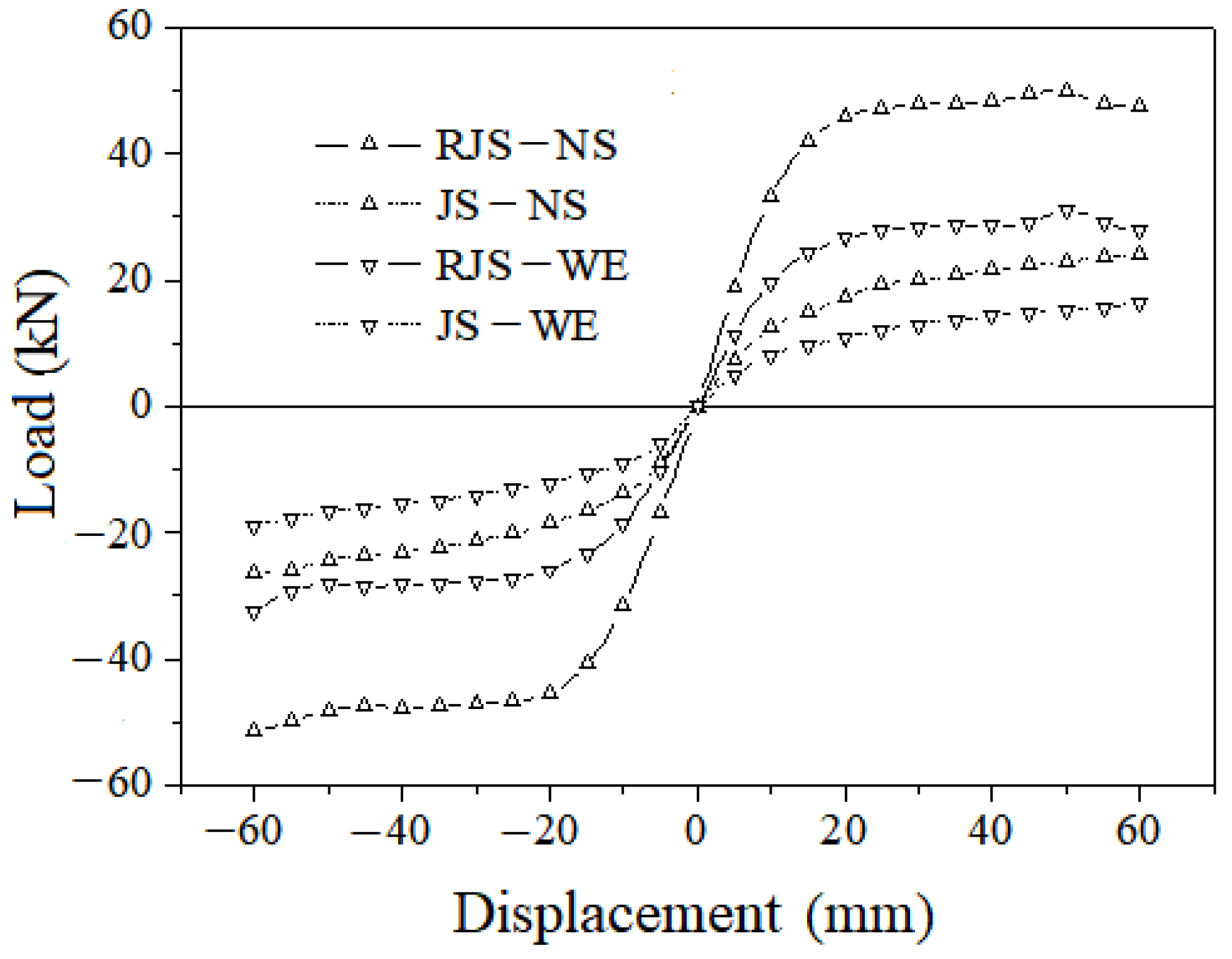
Due to the significant workload and difficulty involved in conducting experiments on spatial nodes, this study only uses numerical simulations. The beam–column dimensions and reinforcement are consistent with the experimental specimens, with only the perpendicular beams extended to match the length of the main beam. The main beam is designated as the north–south beam (NS), and the perpendicular beam is the east–west beam (WE). Loading is applied simultaneously on two beams in both directions, for example, loading is applied downward on the north and west beams simultaneously, and upward on the south and east beams simultaneously, and then reversed, resulting in a load direction at a 45° angle to the column axis. The loading procedure is the same as before.
The skeleton curves of the spatial components before and after strengthening are shown in
Figure 15. It can be observed that the load-bearing capacity of both beams in the strengthened components has significantly increased without noticeable degradation. This indicates a change in the failure mode of the node, with no bond failure occurring in the reinforcement bars, resulting in improved shear strength and stiffness of the node, and an enhancement in seismic performance.
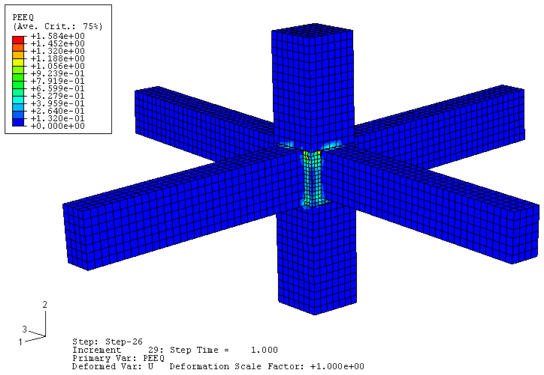
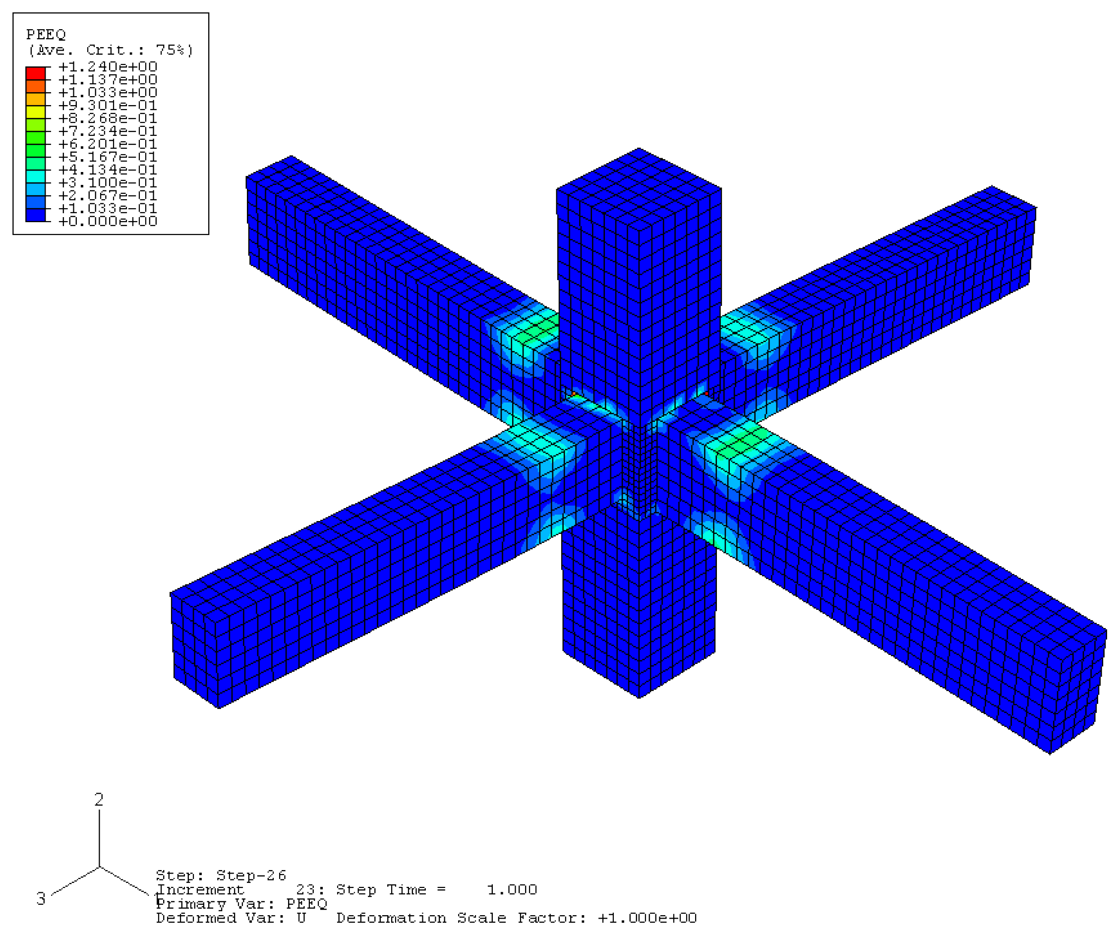
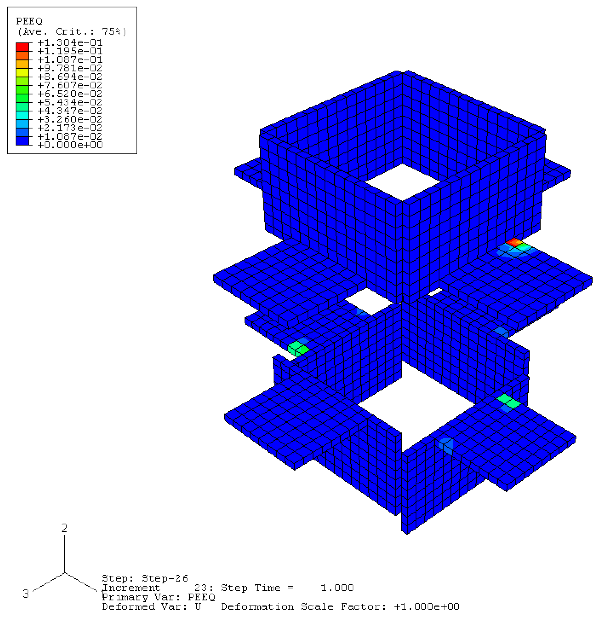
The equivalent plastic strain between the node concrete and angle steel is shown in
Figure 16,
Figure 17 and
Figure 18. It can be seen that the node core area under bi-directional loading experiences high shear forces, and bond degradation along the reinforcement bars occurs early in the loading history, resulting in degradation of the beam plastic hinge region and failure concentrated in the node core area due to shear failure. In contrast, the failure of the strengthened components occurs in the relocated plastic hinge region, providing effective protection to the node core area and preventing its failure. The angle steel undergoes plastic deformation at the corner under bi-directional loading.
6. Conclusions
Through the simulation and analysis of 39 different conditions of joints, the effects of design parameters such as concrete strength grade, axial compression ratio, transverse reinforcement characteristic values, and angle steel type on the strengthening effectiveness were compared and analyzed. The changes before and after the strengthening of bi-directional loaded spatial nodes were simulated and compared. The following conclusions were drawn:
The utilization of angle steel in concrete beam–column joints can effectively enhance both the strength and stiffness of the strengthened nodes. As the concrete strength grade rises, the load-bearing capacity of these strengthened nodes shows a corresponding increase. Nevertheless, once the concrete strength grade surpasses C60, the augmenting effect of the angle steel strengthening becomes notably less pronounced.
When the axial compression ratio is below 0.6, the employment of angle steel to strengthen concrete beam–column joints leads to no remarkable change in the load-bearing capacity of the strengthened nodes. In contrast, once the axial compression ratio exceeds 0.6, the load-bearing capacity of the nodes strengthened with angle steel drops significantly. This indicates that within a certain range of the axial compression ratio, the strengthening effect of angle steel remains relatively stable, while beyond this critical value, the effectiveness of angle steel strengthening is severely affected, highlighting the importance of considering the axial compression ratio when using angle steel to enhance the performance of concrete beam–column joints.
When using angle steel to strengthen the performance of concrete beam–column joints, the stirrup ratio is found to have a negligible impact on the shear resistance capacity of the strengthened nodes. This phenomenon indicates that, within the scope of enhancing the mechanical properties of beam–column joints with angle steel, simply increasing or decreasing the stirrup ratio does not lead to any substantial improvement or change in the shear resistance of these joints. As a result, it implies that during the design and construction process aiming at strengthening the joints with angle steel, the focus should perhaps be shifted away from the stirrup ratio and directed towards other more effective parameters or measures that can more significantly enhance the shear resistance of the strengthened nodes.
Research shows that both the length and thickness of the angle steel legs prove to have a definite influence on the strengthening effectiveness. Specifically, these two geometric parameters of the angle steel, namely the leg length and thickness, interact with the concrete structure in a way that impacts how well the angle steel strengthen the joints. This understanding is crucial for optimizing the design of angle steel strengthened beam–column joints, ensuring that the angle steel is utilized most effectively to improve the mechanical properties of the joints, such as strength, stiffness, and ductility.
By using angle steel to strengthen concrete beam–column joints, the plastic hinges at the joints can be relocated outward. This relocating method of plastic hinges can effectively enhance the seismic performance of bi-directional loaded spatial joints. Specifically, the outward relocation of plastic hinges caused by the strengthening of angle steel means that the stress concentration originally concentrated in the core area of the beam–column joints is dispersed. As a result, the core area of the beam–column joints is protected from severe damage during seismic actions. This protection mechanism not only strengthens the beam–column joints but also improves the overall seismic-resistant capacity of the structure, enabling it to better withstand seismic forces and reduce the risk of structural failure.
Author Contributions
Methodology, X.Y. and J.S.; validation, Y.L. and D.J.; investigation, S.D. and G.Z.; writing—original draft preparation, X.Y.; writing—review and editing, X.Y.; funding acquisition, J.S. All authors have read and agreed to the published version of the manuscript.
Funding
This research was funded by National Key Research and Development Program of China grant number 2022YFF0609200 and Shandong Provincial Housing and Urban-Rural Construction Science and Technology Program of China grant number 2022-K7-10 and Shandong Province Undergraduate Teaching Reform Research Project grant number M2022095.
Data Availability Statement
Data is contained within the article.
Conflicts of Interest
Author Shixin Duan was employed by the company Shandong Quality Inspection and Testing Center of Construction Engineering Co., Ltd. And author Guodong Zhao was employed by the company Shandong Academy of Building Research Co., Ltd. The remaining authors declare that the research was conducted in the absence of any commercial or financial relationships that could be construed as a potential conflict of interest.
References
- Lu, L.; Zhang, J.; Zhang, G.; Peng, H.; Liu, B.; Hao, H. The Influence of Box-Strengthened Panel Zone on Steel Frame Seismic Performance. Buildings 2023, 13, 3042. [Google Scholar] [CrossRef]
- Adil, W.; Rahman, F.U.; Ali, Q.; Papakonstantinou, C.G. An Improved Anchorage System for L-Shaped FRP Composites to Enhance the Seismic Response of Beam-Column Joints in a Low-Strength Substandard Reinforced Concrete (RC) Frame. Buildings 2024, 14, 721. [Google Scholar] [CrossRef]
- Adane, M.; Chun, S.; Kim, J. Seismic retrofit of framed structures using a steel frame assembly. Steel Compos. Struct. 2023, 46, 857–865. [Google Scholar] [CrossRef]
- Cao, Q.; Ju, H.; Jia, J.Q.; Zhang, Q.; Zhang, L.H. Seismic performance of reinforced concrete beam-column joint made of post-filling coarse aggregate concrete. Struct. Concr. 2023, 24, 1118–1133. [Google Scholar] [CrossRef]
- Jiang, W.G. Experimental Study on Carbon Fiber Reinforcement of Reinforced Concrete Beam Column Node Composite Members. Ph.D. Thesis, Southeast University, Nanjing, China, 2004. [Google Scholar]
- Ling, Y.H.; Xu, J.H.; Guo, Z.H.; Wen, X.G. Study on seismic behavior of reinforced concrete column-steel beam side joints. J. Asian Archit. Build. Eng. 2021, 20, 44–60. [Google Scholar] [CrossRef]
- Tang, J.R. Seismic Resistance of Reinforced Concrete Frame Joints; Southeast University Press: Nanjing, China, 1989. [Google Scholar]
- Jiang, P.F.; Zheng, H.; Xiong, J.G.; Wen, P.H. Nonlinear elastic-plastic analysis of reinforced concrete column-steel beam connection by RBF-FD method. Eng. Anal. Bound. Elem. 2021, 128, 188–194. [Google Scholar] [CrossRef]
- Jiang, S.; Chen, Q.; Li, C.; Song, H.; Lin, E.; Fu, C. Assessment of Soft-First-Floor Structures Reinforced by Rocking Frame Based on Seismic Resilience. Buildings 2024, 14, 197. [Google Scholar] [CrossRef]
- Shoukry, M.E.; Tarabia, A.M.; Abdelrahman, M.Z. Seismic retrofit of deficient exterior RC beam-column joints using steel plates and angles. Alex. Eng. J. 2022, 61, 3147–3164. [Google Scholar] [CrossRef]
- Saghafi, M.H.; Ali, G. Seismic retrofit of deficient 3D RC beam–column joints using FRP and steel PT rods. Mater. Struct. 2022, 55, 210. [Google Scholar] [CrossRef]
- Akhaveissy, A.H.; Permanoon, A.; Mirzaei, M. Seismic Retrofit of Defective RC Beam-Column Joints. Period. Polytech. Civ. Eng. 2018, 62, 596–611. [Google Scholar] [CrossRef]
- Cai, Z.W.; Liu, X.; Li, L.Z.; Lu, Z.D.; Chen, Y. Seismic performance of RC beam-column-slab joints strengthened with steel haunch system. J. Build. Eng. 2021, 44, 103250. [Google Scholar] [CrossRef]
- Masi, A.; Santarsiero, G.; Nigro, D. Cyclic Tests on External RC Beam-Column Joints: Role of Seismic Design Level and Axial Load Value on the Ultimate Capacity. J. Earthq. Eng. 2013, 17, 110–136. [Google Scholar] [CrossRef]
- Santarsiero, G.; Manfredi, V.; Masi, A. Numerical Evaluation of the Steel Plate Energy Absorption Device (SPEAD) for Seismic Strengthening of RC Frame Structures. Int. J. Civ. Eng. 2020, 18, 835–850. [Google Scholar] [CrossRef]
- Wu, P.; Li, D.; Yu, F.; Fang, Y.; Xiang, G.; Li, Z. Experimental study on bearing capacity of PFCC column-RC beam joint reinforced with CST. Steel Compos. Struct. 2023, 47, 19–36. [Google Scholar] [CrossRef]
- Liu, W.; Zhang, J.; Liu, H.; Wang, F.; Liu, J.; Han, M. Seismic Fragility Analysis of Existing RC Frame Structures Strengthened with the External Self-Centering Substructure. Buildings 2023, 13, 2117. [Google Scholar] [CrossRef]
- Zhao, G.D. Theoretical Analysis and Experimental Research on the Bending Stiffness of Prestressed Steel Reinforced Concrete Beams. Master’s Thesis, Shandong Institute of Architecture and Engineering, Jinan, China, 2005. [Google Scholar]
- Wu, C.L.; Liu, J.M.; Tan, W.Y.; Wang, P.F. Seismic behavior of composite interior joints of prefabricated H-shaped steel reinforced concrete column—Steel beam. Structures 2020, 23, 558–572. [Google Scholar] [CrossRef]
- Zhang, Y.; Ma, W.; Li, X.; Li, K. Experimental Research on Seismic Behavior of Haunched Concrete Beam-Column Joint Based on the Bolt Connection. Sustainability 2022, 14, 15644. [Google Scholar] [CrossRef]
- Sui, L.; Wu, H.; Tao, M.; Jia, Z.; Zhou, T. Seismic performance evaluation of steel moment frames with self-centering energy-dissipating coupled wall panels. Steel Compos. Struct. 2023, 47, 663–677. [Google Scholar] [CrossRef]
- Santarsiero, G.; Masi, A. Seismic Upgrading of RC Wide Beam-Column Joints Using Steel Jackets. Buildings 2020, 10, 203. [Google Scholar] [CrossRef]
- Jiang, H.; Li, J.; Cheng, Q.; Xiao, J.; Chen, Z. Axial behavior of RC column strengthened with SM-CFST. Steel Compos. Struct. 2022, 43, 773–784. [Google Scholar] [CrossRef]
- Santarsiero, G. FE Modelling of the Seismic Behavior of Wide Beam-Column Joints Strengthened with CFRP Systems. Buildings 2018, 8, 31. [Google Scholar] [CrossRef]
- Mou, B.; Yan, X.C.; Qiao, Q.Y.; Zhou, W.Q. Experimental and numerical investigation on exposed RCFST column-base Joint. Steel Compos. Struct. 2022, 45, 749–766. [Google Scholar] [CrossRef]
- Chen, L.B. Analysis of Square Concrete Filled Steel Tube’s Mechanical Behavior in Finite Element Method. Ph.D. Thesis, Wuhan University, Wuhan, China, 2004. [Google Scholar]
- Luat, N.V.; Lee, H.; Shin, J.; Park, J.H.; Ahn, T.S.; Lee, K. Experimental and numerical investigation of RC frames strengthened with a hybrid seismic retrofit system. Steel Compos. Struct. 2022, 45, 563–577. [Google Scholar] [CrossRef]
- Xiao, L.L. Nonlinear Finite Element Analysis of High-Strength Concrete Frame Joints. Ph.D. Thesis, Gansu University of Technology, Lanzhou, China, 2001. [Google Scholar]
- Zhuang, Z. ABAQUS Nonlinear Finite Element Analysis and Examples; Science Press: Beijing, China, 2005. [Google Scholar]
- Teng, Z.M.; Zou, L.X. Nonlinear finite element analysis of reinforced concrete components under cyclic loading. China Civ. Eng. J. 1996, 29, 19–27. [Google Scholar]
- Lubliner, J.; Oliver, J.; Oller, S.; Onate, E. A plastic-damage model for concrete. Int. J. Solids Struct. 1989, 25, 229–326. [Google Scholar]
- Lee, J.; Fenves, G.L. Plastic-damage model for cyclic loading of concrete structures. J. Eng. Mech. 1998, 124, 892–900. [Google Scholar]
Figure 1.
Beam–column combination joint.
Figure 1.
Beam–column combination joint.
Figure 2.
Cross-section of beams and columns.
Figure 2.
Cross-section of beams and columns.
Figure 3.
Experimental strengthened joint.
Figure 3.
Experimental strengthened joint.
Figure 4.
Schematic diagram of loading device.
Figure 4.
Schematic diagram of loading device.
Figure 5.
Hysteresis curve at beam end.
Figure 5.
Hysteresis curve at beam end.
Figure 6.
Finite element analysis model.
Figure 6.
Finite element analysis model.
Figure 7.
Comparison between simulated and experimental values.
Figure 7.
Comparison between simulated and experimental values.
Figure 8.
Equivalent plastic strain for simulation analysis.
Figure 8.
Equivalent plastic strain for simulation analysis.
Figure 9.
Location of analysis units. (a) Longitudinal reinforcement of the beam; (b) longitudinal reinforcement of the column; (c) stirrup reinforcement within the joint; (d) angle steel.
Figure 9.
Location of analysis units. (a) Longitudinal reinforcement of the beam; (b) longitudinal reinforcement of the column; (c) stirrup reinforcement within the joint; (d) angle steel.
Figure 10.
Skeleton curves of joints with different concrete strength grades.
Figure 10.
Skeleton curves of joints with different concrete strength grades.
Figure 11.
Skeleton curves of joints with different axial compression ratios.
Figure 11.
Skeleton curves of joints with different axial compression ratios.
Figure 12.
Skeleton curves of joints with different stirrup ratio.
Figure 12.
Skeleton curves of joints with different stirrup ratio.
Figure 13.
Skeleton curves of joints with different angle steel leg lengths.
Figure 13.
Skeleton curves of joints with different angle steel leg lengths.
Figure 14.
Skeleton curves of joints with different angle steel leg thicknesses.
Figure 14.
Skeleton curves of joints with different angle steel leg thicknesses.
Figure 15.
Skeleton curves of spatial joints.
Figure 15.
Skeleton curves of spatial joints.
Figure 16.
Equivalent plastic strain of JS concrete.
Figure 16.
Equivalent plastic strain of JS concrete.
Figure 17.
Equivalent plastic strain of RJS concrete.
Figure 17.
Equivalent plastic strain of RJS concrete.
Figure 18.
Equivalent plastic strain of RJS angle steel.
Figure 18.
Equivalent plastic strain of RJS angle steel.
Table 1.
Mechanical performance of concrete.
Table 1.
Mechanical performance of concrete.
| Component | fcu (MPa) | ft (MPa) | Ec (×104 MPa) |
|---|
| JC-1, RJC-1 | 13 | 1.45 | 2.2 |
| JC-2, RJC-2 | 39 | 3.188 | 3.06 |
| JC-3, RJC-3 | 57 | — | 3.5528 |
| JC-4, RJC-4 | 66.2 | 4.25 | 3.71 |
| JC-5, RJC-5 | 82.8 | — | 4.1798 |
Table 2.
Parameter values of strengthened joints.
Table 2.
Parameter values of strengthened joints.
| Category | Component | fc (MPa) | Axial Compression Ratio | Stirrup Ratio | Angle Steel (mm) |
|---|
| Comparison component | J | 22.572 | 0.15 | 0.092 | — |
| RJ | ∠200 × 16 |
| Concrete strength grade | JC-1 | 9.88 | 0.15 | 0.211 | — |
| RJC-1 | ∠200 × 16 |
| JC-2 | 29.64 | 0.070 | — |
| RJC-2 | ∠200 × 16 |
| JC-3 | 41.26 | 0.051 | — |
| RJC-3 | ∠200 × 16 |
| JC-4 | 50.312 | 0.041 | — |
| RJC-4 | ∠200 × 16 |
| JC-5 | 59.93 | 0.035 | — |
| RJC-5 | ∠200 × 16 |
| Axial compression ratio | RJA-1 | 22.572 | 0 | 0.092 | ∠200 × 16 |
| RJA-2 | 0.3 |
| RJA-3 | 0.45 |
| RJA-4 | 0.6 |
| RJA-5 | 0.75 |
| Stirrup characteristic value | RJT-1 | 22.572 | 0.15 | 0 | ∠200 × 16 |
| RJT-2 | 0.025 |
| RJT-3 | 0.037 |
| RJT-4 | 0.074 |
| RJT-5 | 0.111 |
| Angle steel model | RJL-1 | 22.572 | 0.15 | 0.092 | ∠100 × 16 |
| RJL-2 | ∠120 × 16 |
| RJL-3 | ∠140 × 16 |
| RJL-4 | ∠160 × 16 |
| RJL-5 | ∠180 × 16 |
| RJL-6 | ∠220 × 16 |
| RJL-7 | ∠240 × 16 |
| RJL-8 | ∠300 × 16 |
| RJD-1 | ∠200 × 10 |
| RJD-2 | ∠200 × 12 |
| RJD-3 | ∠200 × 14 |
| RJD-4 | ∠200 × 18 |
| RJD-5 | ∠200 × 20 |
| RJD-6 | ∠200 × 22 |
| RJD-7 | ∠200 × 24 |
| Spatial joint | JS | 22.572 | 0.15 | 0.092 | — |
| RJS | ∠200 × 16 |
| Disclaimer/Publisher’s Note: The statements, opinions and data contained in all publications are solely those of the individual author(s) and contributor(s) and not of MDPI and/or the editor(s). MDPI and/or the editor(s) disclaim responsibility for any injury to people or property resulting from any ideas, methods, instructions or products referred to in the content. |
© 2025 by the authors. Licensee MDPI, Basel, Switzerland. This article is an open access article distributed under the terms and conditions of the Creative Commons Attribution (CC BY) license (https://creativecommons.org/licenses/by/4.0/).


