Article

Research on the Longitudinal Deformation of Segments Induced by Pipe-Jacking Tunneling over Existing Shield Tunnels

1
China MCC5 Group Corp., Ltd., Chengdu 610063, China
2
Key Laboratory of Traffic Tunnel Engineering, Southwest Jiaotong University, Chengdu 610031, China
3
School of Civil Engineering, Southwest Jiaotong University, Chengdu 610031, China
*
Author to whom correspondence should be addressed.
Buildings 2025, 15(9), 1394; https://doi.org/10.3390/buildings15091394
Submission received: 11 March 2025 / Revised: 7 April 2025 / Accepted: 9 April 2025 / Published: 22 April 2025

Abstract

The prevalence of pipe jacking projects that traverse beneath subway tunnels in urban environments is on the rise, and the construction of pipe jacking can have a considerable effect on the deformation and stress experienced by existing shield tunnel segments. This study aims to assess the impact of pipe jacking construction on the longitudinal deformation of these segments, specifically centering on the pipe jacking project that intersects with Metro Line 6 in Chengdu. Initially, seven monitoring sections were established on-site to evaluate the vertical and horizontal deformation characteristics of each section. Then, a numerical model was developed using FLAC3D software to simulate the pipe jacking construction in relation to the existing shield tunnel. This model is designed to further explore the effects of the geological strata and the relative spatial arrangement of the two structures on the deformation of the shield tunnel. The findings reveal that under same geological conditions, the effects arising from the vertical clearance between the pipe jacking and the shield tunnel are significant. Specifically, when the vertical clearance is reduced from 2.4 m (the diameter of the pipe) to 1.4 m, the maximum vertical deformation at the crown experiences a 14.40% increase, while the maximum differential settlement between the pipe rings escalates by 46.66%. It is advisable that the separation between the two during construction should not fall below the diameter of the pipe. This research could serve as a valuable reference for the safeguarding of existing shield tunnels in analogous projects.

1. Introduction

The swift advancement of urbanization necessitates the modernization of underground pipeline systems in numerous urban areas. The pipe jacking technique is commonly utilized due to its efficiency, convenience, and minimal disruption to surface traffic. Nevertheless, the application of this method can lead to the deformation of adjacent soil layers and a redistribution of stress [1,2,3,4,5]. When the pipe jacking passes through the shield tunnels from above, these tunnels may experience negative impacts, resulting in uneven stress distribution and potential deformation of the tunnel segments [6,7,8,9]. Therefore, it is imperative to conduct a thorough analysis of pipe jacking construction in relation to existing shield tunnels, as well as to comprehend the deformation patterns of the tunnel segments, in order to ensure the safety of adjacent underground structures.
In recent years, researchers and scholars have investigated the effects of newly constructed tunnels on the adjacent environment. The predominant methodologies utilized in this research encompass theoretical derivation [10,11,12], model experimentation [13,14,15,16], field monitoring [17,18,19,20], and numerical simulation [5,21,22,23]. Most of these studies focus on the effect of the shield method for this application. However, the minority of studies specifically address the pipe jacking technique for traversing existing shield tunnels. Wei [24] utilized the principle of minimum potential energy to forecast the longitudinal deformation of existing shield tunnels when a new tunnel is constructed above them, corroborating their results with empirical engineering data (the existing shield tunnel is situated approximately 20 m below the surface, with an 8 m separation from the new shield tunnel). Yu [25] formulated a coupled equilibrium equation for the tunnel and the surrounding soil, initially determining the displacement of the layered soil beneath the newly excavated tunnel through the Mindlin solution, and subsequently deriving the longitudinal displacement solution for the existing shield tunnel, using the crossing of the new tunnel over Shanghai Metro Line 2 as a case study (the existing shield tunnel is buried 24 m deep, with a proximity of about 5 m to the new tunnel). Xu and Du [26] introduced the Timoshenko beam model alongside the Pasternak foundation model to derive the differential equation that governs the additional stress in the soil beneath the newly constructed shield tunnel and the longitudinal deformation of the existing tunnel, validating their methodology with the example of the new tunnel crossing Wuhan Metro Line 2 (the existing shield tunnel is buried 25.9 m deep, with a clearance of 11.6 m from the new shield tunnel). Zhang [27] developed a three-dimensional numerical model to simulate the entire crossing process, confirming the model’s efficacy through measured data, and exploring the soil–structure interaction mechanisms between the existing twin lines (the existing shield tunnel is buried approximately 22 m deep, with a clearance of 7.35 m from the new shield tunnel).
In the previously examined cases of shield tunneling construction occurring above existing shield tunnels, it is generally noted that the spatial separation between the new line and the adjacent existing shield tunnel is greater than one shield tunnel diameter. Numerous studies have indicated that maintaining a clearance exceeding one shield tunnel diameter between the two tunnels contributes to enhanced safety [28,29,30,31]. In contrast, instances of pipe jacking construction situated above existing shield tunnels, where the separation is less than one shield tunnel diameter, are more frequently observed. Xu [8] conducted a field monitoring study to evaluate the effects of jacking box culverts on the structural integrity of existing shield tunnels, reporting that the existing shield tunnel is located at a depth of 11.75 m, with a separation of 4.3 m from the box culvert. Jiang [32] utilized FLAC3D 6.0 finite difference software to model a rectangular pipe jacking operation intersecting an existing shield tunnel, investigating the impact of buoyancy counterweights on the deformation of the existing shield tunnel, which is buried at a depth of approximately 12 m and positioned 3.05 m from the pipe jacking. Ying [33] assessed the implications of double-line pipe jacking construction on the structural integrity of existing shield tunnels through field data analysis, thereby affirming the applicability of the Peck formula; the existing shield tunnel structure is situated at a depth of 10.28 m, with a clearance of 2 m from the pipe jacking. He [6] explored the scenario of rectangular pipe jacking crossing an existing shield tunnel within soft soil layers, where the existing shield tunnel is buried at a depth of approximately 12 m, with a minimal clearance of 0.977 m from the existing shield tunnel.
Currently, there are relatively few studies on the impact of small-clearance pipe jacking construction on shield tunnels. Previous studies have primarily focused on the effects of construction parameters. These parameters are related to the pipe jacking machine and reinforcement techniques on shield segments [32,34,35]. However, there is a conspicuous absence of studies. These studies should investigate how the spatial arrangement of new pipelines affects the integrity of existing shield tunnel segments. The spatial arrangement includes specifically crossing angles and clearances. To address this gap, the present paper employs the pipe jacking construction of the Chengdu Metro Line 6 project as a case study, conducting a thorough analysis of the deformation patterns observed in shield tunnel segments during the pipe jacking process. This analysis is supported by a combination of field monitoring and numerical simulation methodologies. Additionally, the study explores the disturbance patterns experienced by shield tunnel segments due to pipe jacking construction across various geological formations. By examining the varying intersection angles and clearances between the pipe jacking operation and the existing shield tunnel, the research further investigates the deformation characteristics of the existing shield tunnel segments. The primary aim of this research is to clarify the influence of two aspects. One aspect is the geological strata where the shield tunnel is located. The other is the relative spatial positioning of both the new pipelines and the existing shield tunnel during the pipe jacking construction process. The research results can serve as a valuable reference. This reference is for determining an appropriate construction site for analogous projects. Ultimately, this study can serve as a valuable reference for the safeguarding of existing shield tunnels in analogous projects.

2. On-Site Monitoring and Analysis of Shield Tunnel Deformation

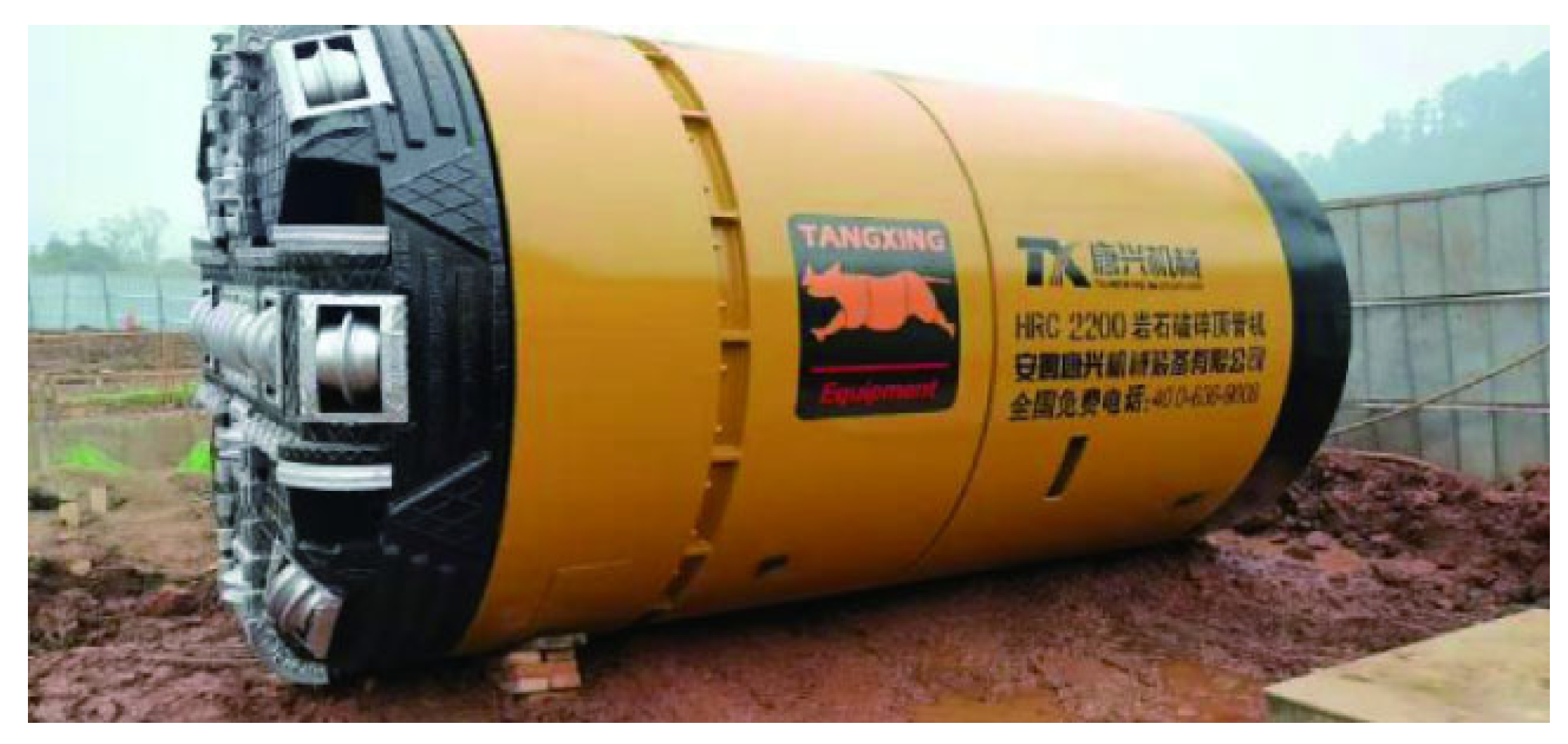
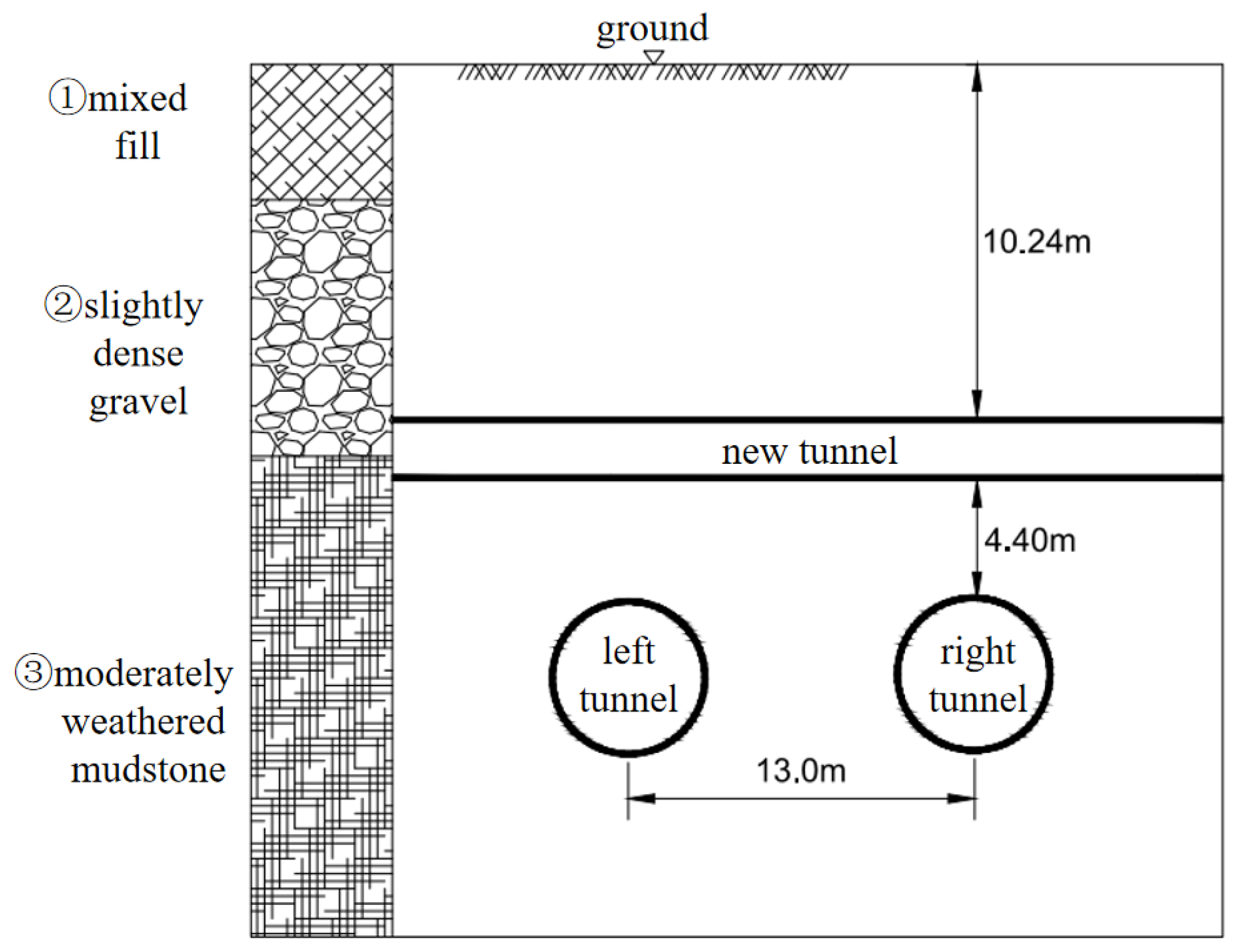
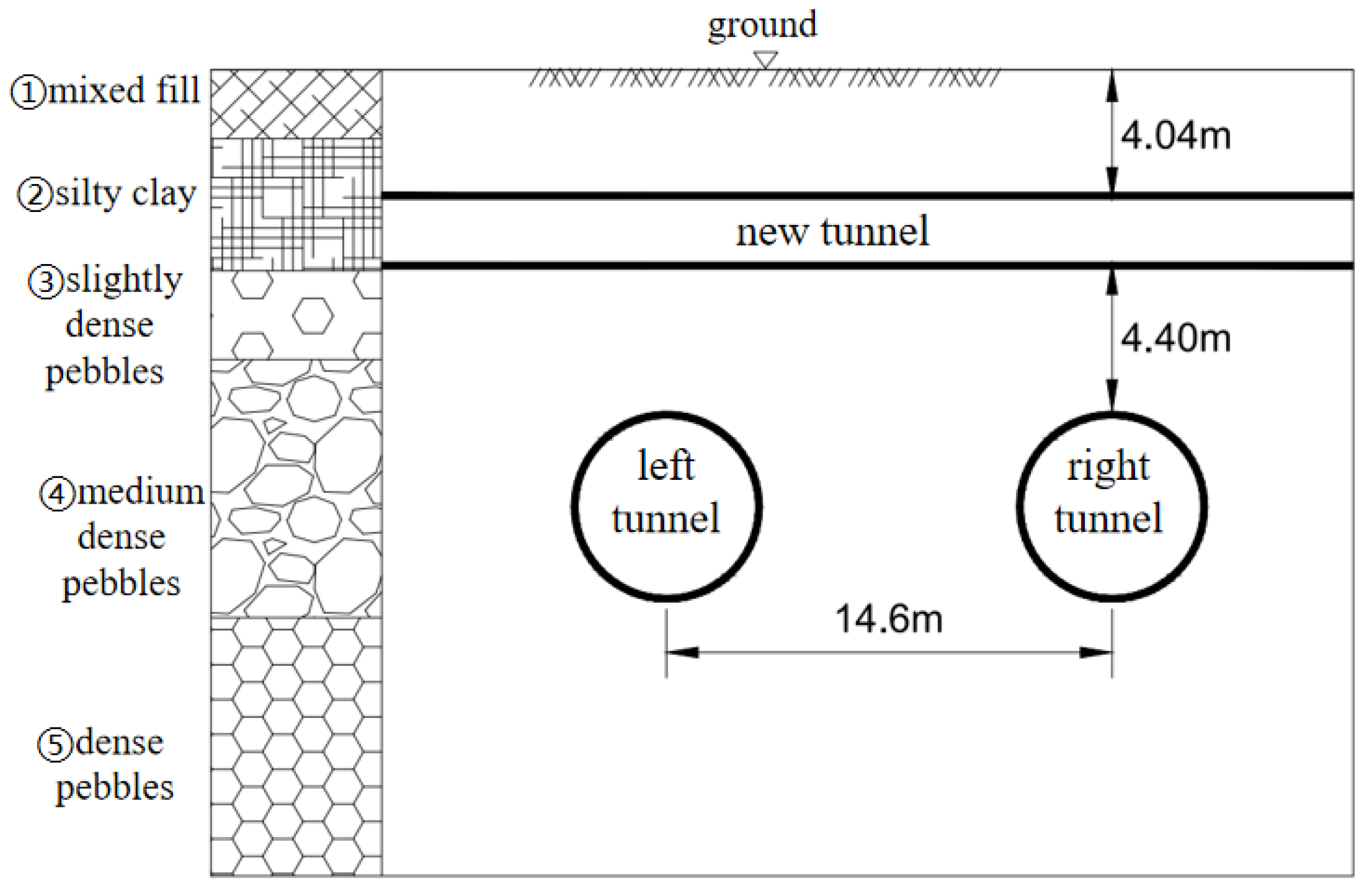
2.1. Overview of the Project and Configuration of Monitoring Points

The project is situated within the context of a pipe jacking operation that intersects with Metro Line 6 in the Chengdu region, specifically in the Jinjiang West area of the Tianfu New District. The pipe jacking segments employed in this endeavor are made from C50 concrete prefabricated segments, characterized by an inner diameter of 2000 mm and an outer diameter of 2400 mm. Furthermore, the lining segments of the shield tunnel are also constructed from C50 concrete prefabricated segments, which are connected using bolts and measure 1500 mm in length per ring. The shield tunnel itself has an inner diameter of 5400 mm and an outer diameter of 6000 mm. As depicted in Figure 1, the operation utilizes the HRC2000 (Tangxing Technology, Chengdu, China) rock-breaking pipe jacking machine, which has an inner diameter of 2000 mm, an outer diameter of 2420 mm, and a length of 5200 mm.
As illustrated in Figure 2, the geological stratigraphy of the project site, arranged from the surface downward, comprises mixed fill, slightly dense gravel, and moderately weathered mudstone. The area designated for pipe jacking excavation is situated at the interface between the slightly dense gravel and the moderately weathered mudstone, with a maximum burial depth of 10.24 m for the pipe jacking section. The existing shield tunnel is a double-line structure, with both lines fully encased within the moderately weathered mudstone, exhibiting a horizontal separation of 13.0 m and a burial depth of 17.24 m. The minimum clearance between the pipe and the shield tunnel is merely 4.4 m, forming an included acute angle of 68°, which exemplifies a typical scenario of close-proximity construction with minimal spacing.
To facilitate a thorough analysis of the deformation patterns exhibited by the existing shield tunnel structure during the pipe jacking phase, seven monitoring sections have been established along the left line of Metro Line 6, with each section spaced 7.5 m apart, as depicted in Figure 3. Each section is outfitted with a vertical displacement measurement point and a horizontal displacement measurement point. The vertical displacement measurement point is positioned near the tunnel vault (designated as measurement point number DM*-1). Additionally, the horizontal displacement measurement point is located at the left haunch of the tunnel (designated as measurement point number DM*-2). The asterisk (*) signifies the section number. The precise locations and the positive direction of the displacement at the measurement points are illustrated in Figure 4.

2.2. Analysis of Displacement Monitoring Data for Existing Shield Tunnel Structures

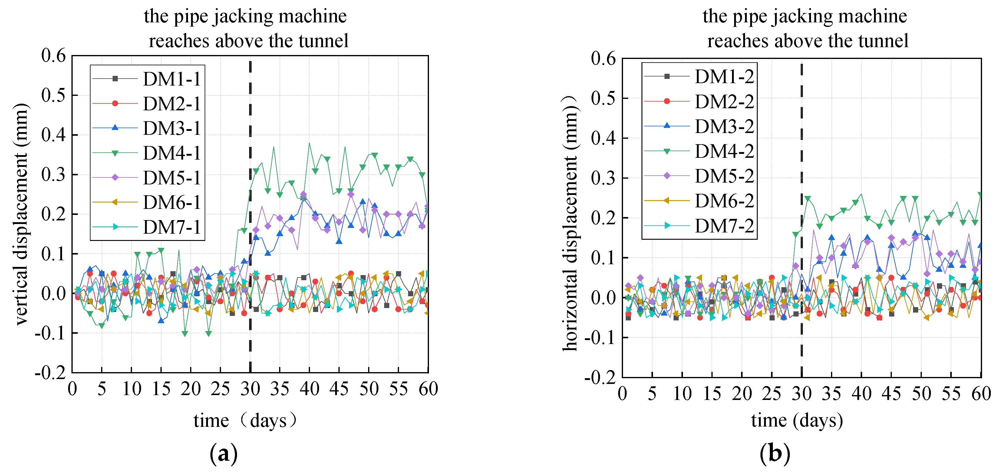
2.2.1. Analysis of Cumulative Deformation

Figure 5a depicts the cumulative time history curve of vertical displacement recorded at measurement point 1. The data reveal that prior to the passage of the pipe jacking machine through the tunnel, the vertical displacement of the tunnel structure remains relatively minor, primarily fluctuating within 0.1 mm. However, subsequent to the passage of the pipe jacking machine, there is a notable increase in vertical displacements at sections DM3, DM4, and DM5, which are in closest proximity to the newly constructed pipe jacking channel. The vertical deformation observed in the existing shield tunnel structure is primarily attributed to the unloading effect resulting from the pipe jacking excavation. Notably, section DM4, located directly beneath the pipe jacking axis, experiences the most significant disturbance, with the maximum vertical displacement recorded at measurement point 1 of section DM4 reaching 0.38 mm.
Figure 5b displays the cumulative time history curve of horizontal displacement measured at measurement point 2; the data suggest that the impact of the jacking construction on the horizontal displacement of the tunnel predominantly occurs after the jacking machine has passed through the tunnel, and during this perio, there is a significant increase in horizontal displacements observed at sections DM3, DM4, and DM5. The primary factor contributing to the horizontal deformation of the existing shield tunnel structure is the pressure exerted by the soil chamber of the jacking machine on the soil in front of the face. Additionally, friction between the pipe segments and the surrounding soil layers serves as a secondary contributing factor. The DM4 section, which is situated directly beneath the axis of the jacking pipe, experiences the most considerable disturbance, with the maximum horizontal displacement at measurement point 2 of the DM4 section reaching 0.26 mm.

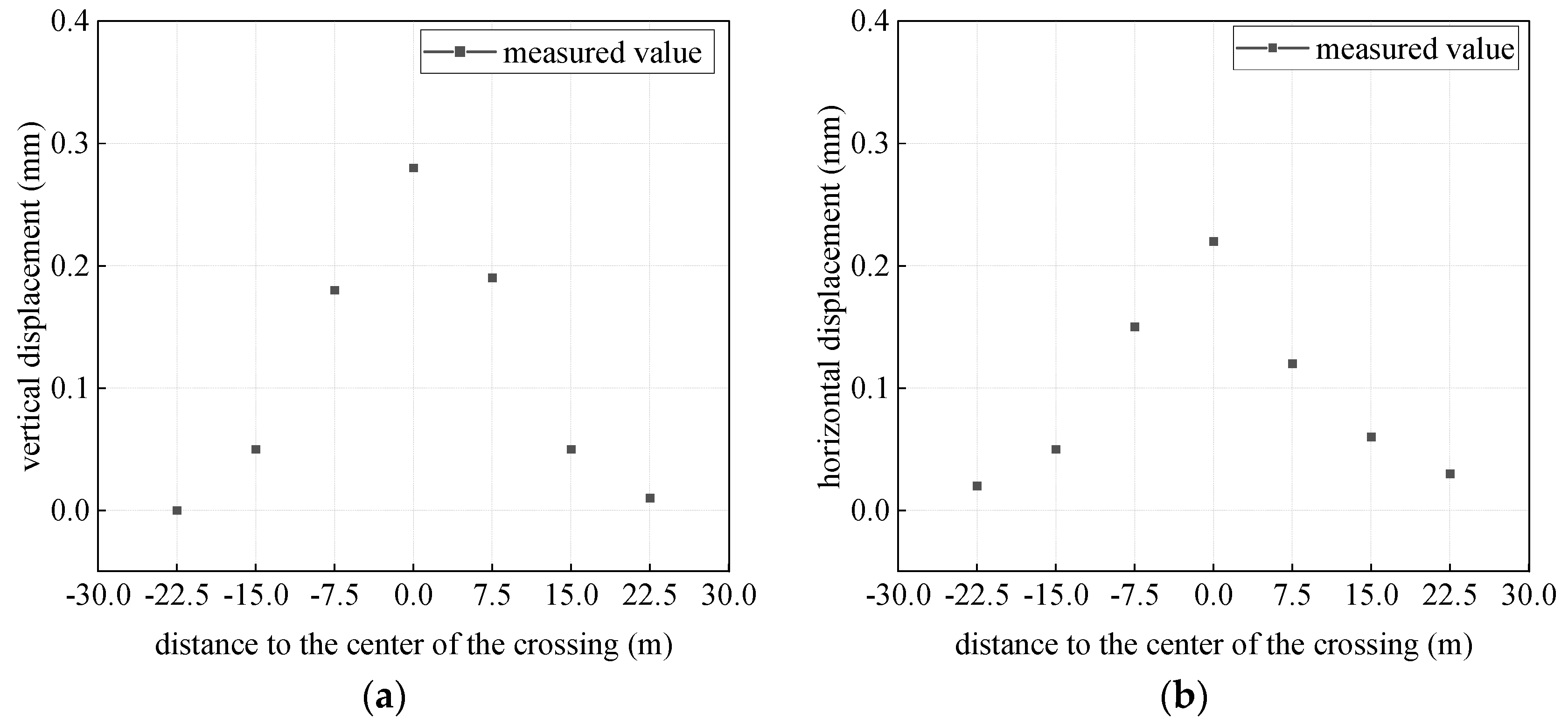
2.2.2. Analysis of Longitudinal Deformation

In order to examine the longitudinal deformation patterns of the existing shield tunnel segments subsequent to the completion of pipe jacking construction, the final displacements at each measurement point were documented, leading to the creation of a longitudinal deformation scatter plot, as illustrated in Figure 6. The final vertical displacement recorded at measurement point 1 across each section is depicted in Figure 6a. This figure reveals that, as a result of the excavation unloading effect associated with the pipe jacking process, the existing shield tunnel structure exhibits a “V”-shaped vertical deformation along its longitudinal axis, with the maximum vertical displacement of 0.28 mm occurring directly beneath the pipe segment. Furthermore, the final horizontal displacement recorded at measurement point 2 for each section is shown in Figure 6b. The data suggest that, influenced by the pressure within the mud-water chamber of the pipe jacking machine and the frictional forces between the pipe and the surrounding soil, the existing shield tunnel structure also displays a “V”-shaped horizontal deformation along the longitudinal direction, with the maximum horizontal displacement of 0.22 mm occurring directly beneath the pipe segment.

3. Numerical Model

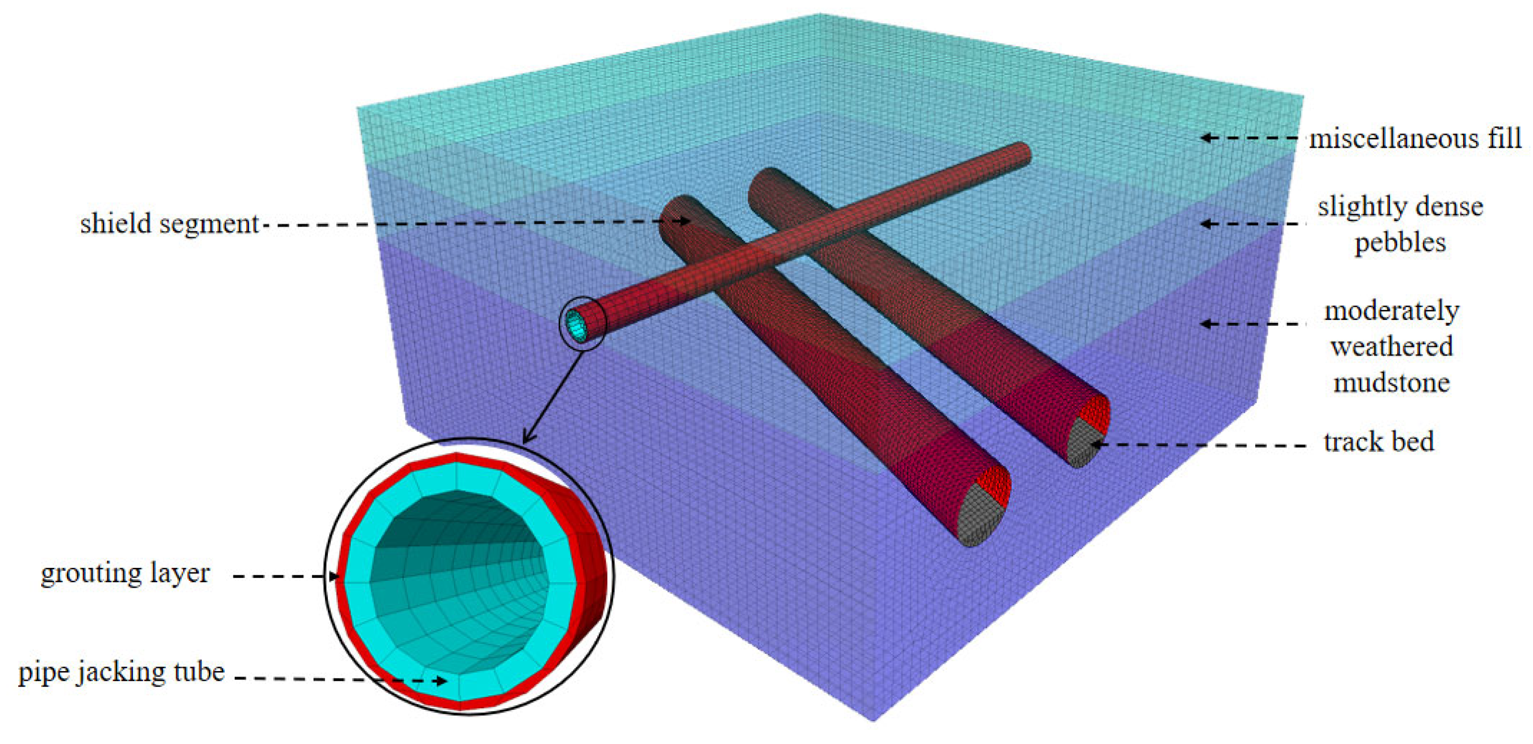
3.1. Establishment of Numerical Model

This article presents a study of a pipe jacking project that intersects with the Chengdu Metro Line 6, employing the finite difference software FLAC3D 6.0 to simulate the construction process and to develop a numerical calculation model, as illustrated in Figure 7. The pipe jacking operation occurs at a depth of 10.24 m, while the shield tunnel is located at a depth of 17.24 m. The angle between the pipe jacking and the tunnel is recorded at 68°, with a vertical clearance of 4.4 m, and the excavation direction is aligned with the positive Y-axis. The effects produced during the pipe jacking construction are estimated to extend approximately 3 to 5 times the diameter of the tunnel. To alleviate the influence of boundary effects, the left and right boundaries, as well as the lower boundary of the three-dimensional tunnel mesh model, are designed to extend beyond 5 times the width of the tunnel excavation. The dimensions of the developed three-dimensional model in the X, Y, and Z axes are 60 m × 60 m × 41.7 m, with normal displacement constraints imposed around the model and at its base, the model comprises a total of 280,022 elements and 226,185 nodes. In the simulation of the construction process, initial ground stress is uniformly applied to the entire model, and the displacement is set back to zero. Subsequently, the built-in Fish programming language of FLAC3D is utilized to execute the cyclic excavation of the pipe jacking, with each excavation phase extending 3 m until completion.

3.2. Assumptions of Numerical Model

In the context of practical engineering applications, the soil strata within the influence zone of pipe jacking excavation are identified as a nonlinear material that encompasses solid, liquid, and gas phases. Effectively modeling the real conditions experienced during the excavation process with a single mathematical constitutive model poses considerable difficulties. This article establishes certain assumptions and simplifications pertaining to the materials utilized within the numerical model: (1) The soil layer is represented as an isotropic, continuous, homogeneous elastoplastic material that conforms to the Mohr-Coulomb yield criterion. (2) The pipe jacking segments, shield segments, grouting layer and the track bed within the tunnel are characterized as isotropic linear elastic materials, omitting the influence of joints between shield segments. (3) The model does not incorporate secondary consolidation settlement or creep deformation of the soil resulting from the pipe jacking process. (4) The pipe jacking operation is assumed to be a linear push, neglecting any potential deflection issues. (5) It is consistently assumed that the pipe segments maintain tight contact with the surrounding soil, with no detachment or relative sliding occurring throughout the deformation process. The material parameters are comprehensively outlined in Table 1.

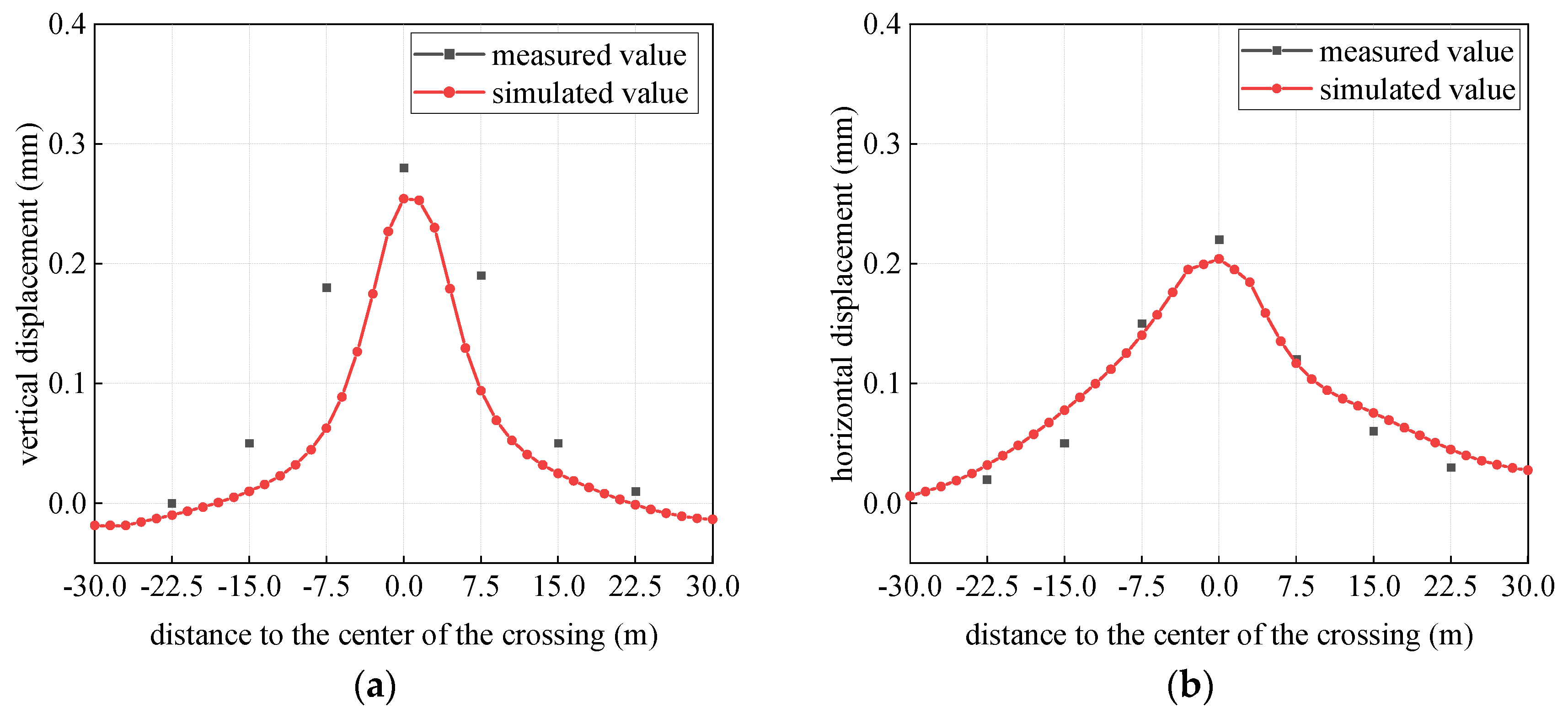
3.3. Validation of Numerical Model

Upon the conclusion of the pipe jacking construction, the vertical and horizontal deformation cloud diagrams of the existing shield tunnel are presented in Figure 8. It is evident that the upper section of the shield tunnel experiences more substantial effects, with the vertical deformation at the vault exhibiting the most significant magnitude, attaining a peak value of 0.32 mm. To evaluate the accuracy of the numerical model, the final displacements recorded at each measurement point were compared with the results obtained from the numerical simulation after the completion of the pipe jacking construction. Figure 9a illustrates the comparison of the measured and simulated values at measurement points 1. Both the simulated and measured values display a “V”-shaped vertical deformation along the longitudinal axis of the shield tunnel structure, with the peak vertical deformation occurring at the tunnel cross-section directly beneath the pipe segment. The simulated value is 0.25 mm, while the measured value is 0.28 mm, so there is a discrepancy of 10.71%. Similarly, Figure 9b presents the comparison of the measured and simulated values at measurement points 2. In this instance, the simulated and measured values exhibit a “U”-shaped horizontal deformation along the longitudinal direction of the shield tunnel structure, with the maximum horizontal deformation also occurring at the tunnel cross-section directly beneath the pipe segment. The simulated value is 0.20 mm, and the measured value is 0.22 mm, so there is a discrepancy of 9.09%. The observed congruence in the deformation patterns of the shield tunnel structure, as indicated by both the simulated and measured values, along with the errors in maximum vertical and horizontal deformations being approximately 10%, suggest that the numerical calculation model is reasonably valid.

4. Results and Discussion

In comparable engineering contexts, it is essential to recognize that, alongside variations in geological conditions, the relative spatial arrangement between newly constructed and existing tunnels holds significant importance. The angles of intersection typically range from 20° to 90° [6,24,26,27,34,36], while the vertical clearance during construction in close proximity varies between 1 m and 12 m [7,8,9,24,32,33]. The cases discussed indicate that shield tunnel segments situated near the center of the intersection are likely to experience uplift deformation, a conclusion that is corroborated by the field monitoring and numerical analyses conducted in this study. However, these instances do not clarify the influence of differing geological conditions, intersection angles, and spacing on the structural integrity of the existing shield tunnel. Therefore, this section seeks to further investigate the effects of variations in geological conditions and spatial configurations on the structural integrity of the existing shield tunnel through the utilization of numerical simulations.

4.1. Different Geological Conditions of the Shield Tunnel

The engineering geological formations encountered by the Chengdu Metro’s shield tunnel predominantly comprise gravel and mudstone strata. The gravel strata are characterized by relatively weak and loose properties, which lead to a significant disturbance of the shield tunnel structure during the pipe jacking construction occurring above. This section conducts a thorough comparative analysis of the impacts of shield tunnels located within the two strata previously discussed. Geological survey data relevant to the shield tunnel in moderately weathered mudstone strata is presented in Section 2. The geological conditions for the shield tunnel located in gravel strata are depicted in Figure 10, with various strata parameters detailed in Table 2. The vertical clearance between the shield tunnel in the gravel strata and the pipe jacking operation is recorded at 4.4 m, with an intersection angle of 68 degrees.

4.1.1. Longitudinal Deformation of Shield Segments

The process of pipe jacking construction induces deformation in existing shield tunnels due to the movement of soil. Figure 11 illustrates the vertical displacement cloud diagram of the surrounding soil in relation to the shield tunnel in various strata. It is evident that, in comparison to the moderately weathered mudstone strata, the gravel strata experience a more pronounced impact from construction disturbances. Figure 12 presents the longitudinal deformation curve of the shield tunnel structure, in the weathered mudstone strata of Line 6, the maximum vertical deformation of the shield tunnel arch is recorded at 0.26 mm. In contrast, within the gravel strata of Line 5, this maximum vertical deformation escalates to 2.67 mm, indicating an increase of nearly tenfold. The effect of pipe jacking construction on the deformation of existing shield tunnels is significantly influenced by the properties of the surrounding soil. Specifically, gravel strata exhibit a notable reduction in both deformation modulus and cohesion when compared to moderately weathered mudstone strata. Under the same unloading conditions, the primary determinant of tunnel deformation is the deformation modulus of the surrounding soil layer. Soils with a lower deformation modulus show reduced resistance to deformation. As a result, this leads to greater deformation of the existing shield tunnel. Additionally, gravel strata lack cohesion. This lack increases their vulnerability to shear failure. As a consequence, it exacerbates the disturbance that the shield tunnel experiences.

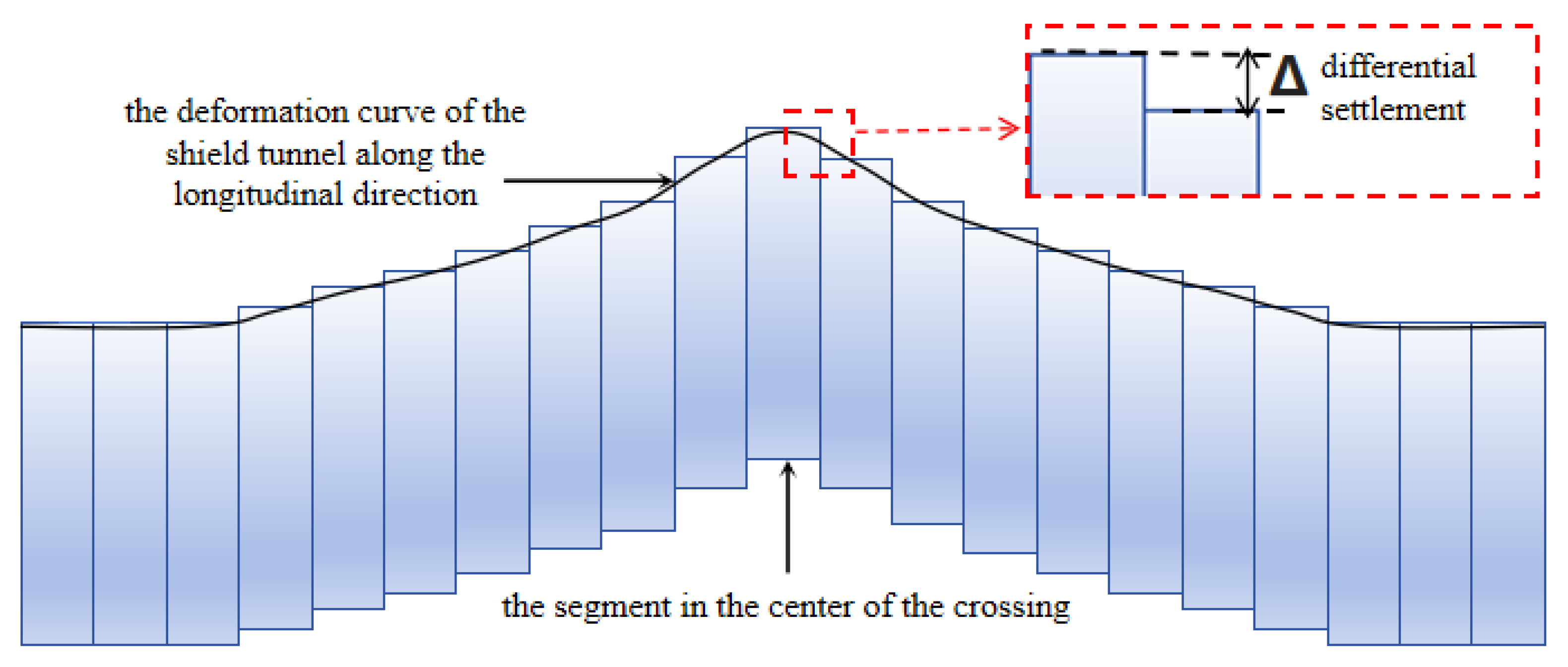
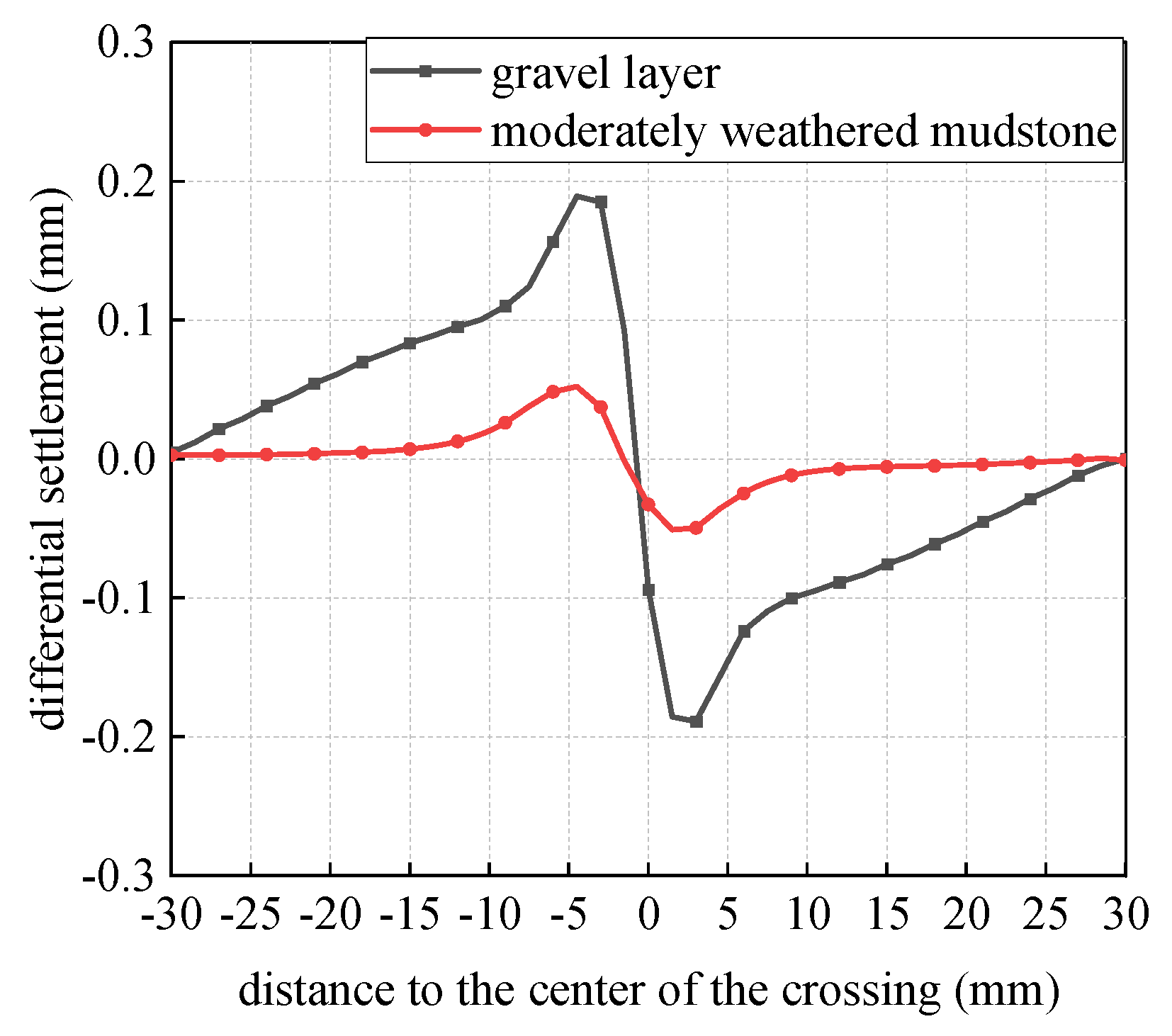
4.1.2. Differential Settlement of Shield Segments

Throughout the pipe jacking construction process, the existing shield tunnel structure is susceptible to considerable longitudinal deformation, which may lead to differential settlement among adjacent segments, as depicted in Figure 13, such occurrences pose a risk to the structural integrity and long-term safety of the system, potentially leading to issues such as water infiltration in the shield tunnel segments due to misalignment. Therefore, it is imperative to study the patterns of differential settlement between segments to ensure the preservation of the shield tunnel structure.
Figure 14 depicts the differential settlement curve recorded among the segments of the shield tunnel, the data reveal that the shield segments situated within a 10 m radius of the crossing center undergo substantial disturbance. This occurrence can be ascribed to the excavation and unloading effects linked to the jacking pipe, which may generate additional stress within the shield tunnel structure. The impact of this additional stress is primarily concentrated within a 10 m radius of the crossing center, where the disparity in additional stress among the segments is particularly marked, resulting in significant differential settlement among the segments. The differential settlement of shield tunnel segments within gravel strata is significantly greater than that in moderately weathered mudstone strata, which can be attributed to the loose characteristics of the gravel layers. As depicted in Figure 14, the maximum differential settlement recorded for shield tunnel segments in moderately weathered mudstone strata is 0.056 mm. In comparison, the maximum differential settlement in moderately dense gravel strata reaches 0.201 mm, having an increase of 258.9%.
In summary, when maintaining a uniform spacing and angle between the pipe and the existing shield tunnel, the deformation and differential settlement of the shield segments in gravel strata are more pronounced than those in mudstone strata. Therefore, it is essential to implement increased precautions to safeguard the integrity of the shield tunnel structure located within gravel strata during the construction of the jacking pipe. With regard to the characteristics of soil strata, particular attention must be directed towards the protection of shield tunnel structures located within soil layers that exhibit a low deformation modulus and low cohesion. In practical engineering contexts, methods such as grouting can be utilized to improve the stability of the interlayer soil, thereby reducing disturbances to the existing shield tunnels.

4.2. Different Angles Between Pipes and Shield Tunnels

In comparable engineering projects, newly constructed tunnels intersect with existing tunnels at various angles, primarily between 20° and 90° [6,24,26,27,34,36]. To assess and compare the impact of different intersection angles on the longitudinal deformation of shield tunnels during the pipe jacking construction process, we examine the case of a subway shield tunnel situated within sandy gravel strata (comprehensive geotechnical data are presented in Section 3.2). It is important to note that the angle of 68° corresponds to the actual angle utilized in this project. We designed the analysis to have the interval change at every nearly 23°. For this analysis, we have selected four intersection angles: 22°, 45°, 68°, and 90° between the new pipe jacking channel and the existing tunnel.

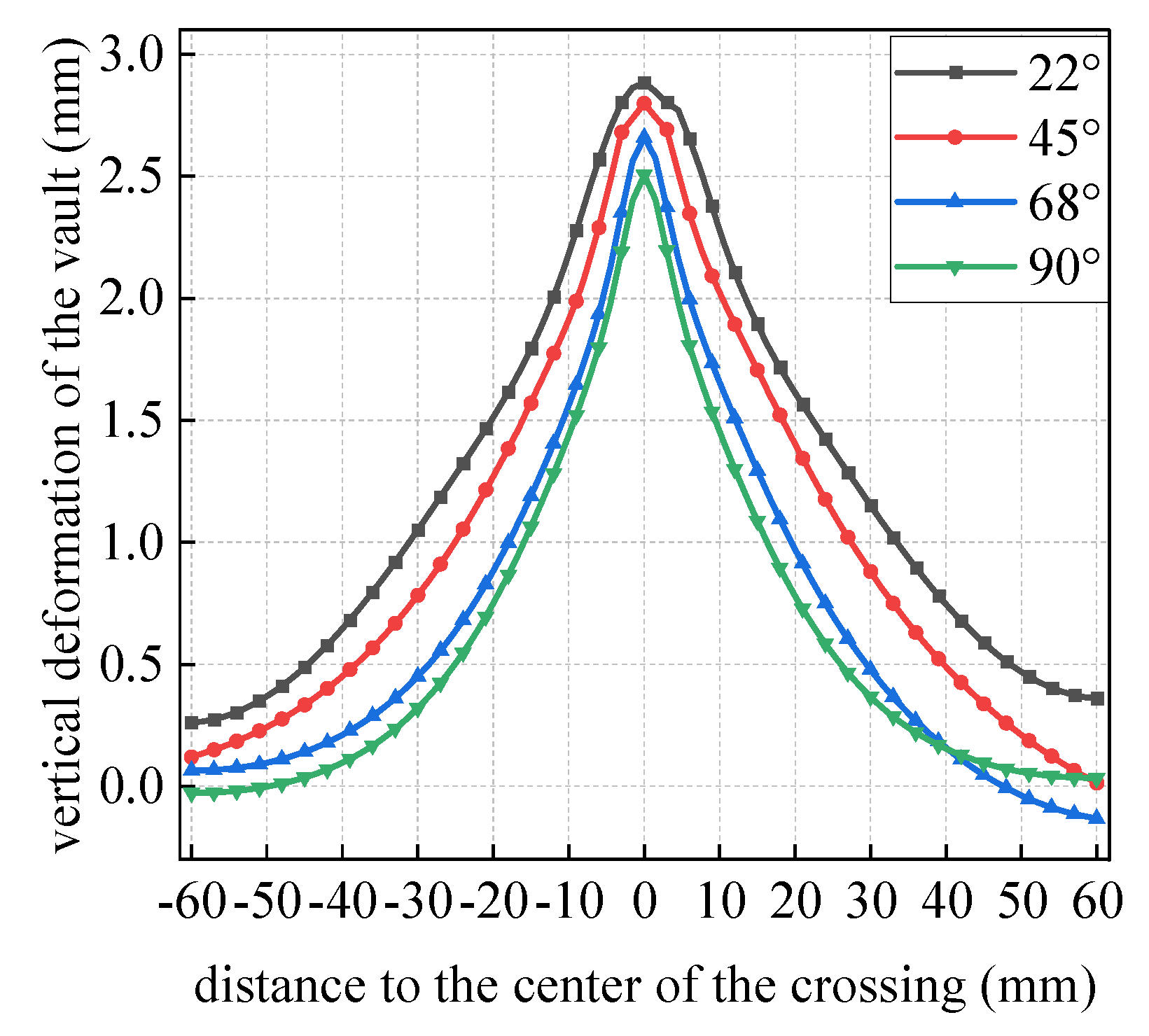
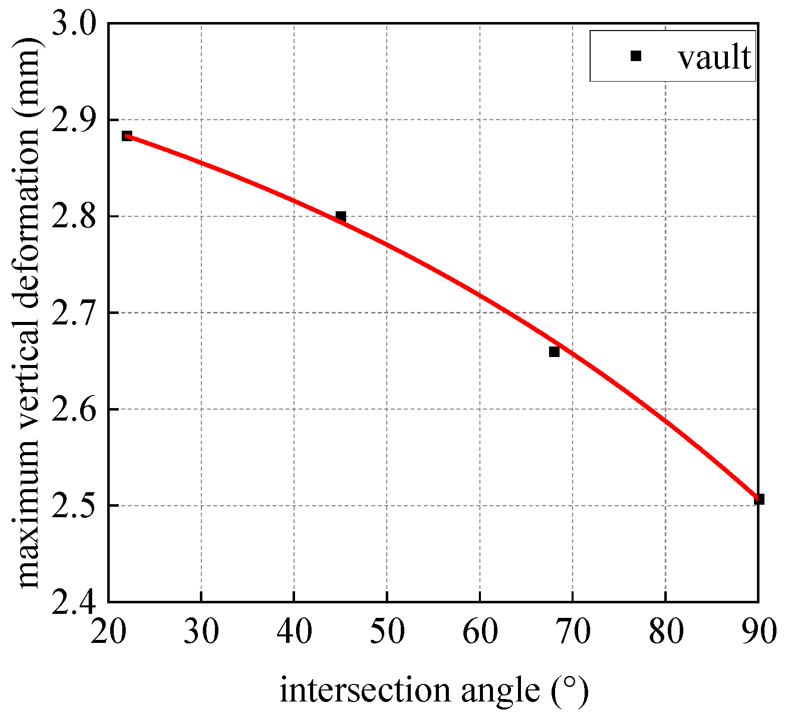
4.2.1. Longitudinal Deformation of Shield Segments

Figure 15 presents cloud diagrams that represent the vertical displacement of the surrounding soil in proximity to existing shield tunnels. It can be observed that as the intersection angle increases, the extent of the affected surrounding soil around the shield tunnel diminishes. Figure 16 presents the deformation curves of the shield tunnel structure along its longitudinal axis at various intersection angles. The shield tunnel structure exhibits a “V”-shaped vertical deformation across different intersection angles, with the maximum vertical deformation occurring at the section directly beneath the pipe segment. As the intersection angle between the pipe and the shield tunnel increases, the vertical deformation at the apex of the shield tunnel decreases. This phenomenon can be primarily attributed to the fact that a larger intersection angle results in a diminished overlapping area between the pipe and the shield tunnel, which subsequently reduces the unloading area of the shield tunnel. In contrast to small-angle crossings, during large-angle crossings, the shield tunnel segments located near the crossing center experience a marginally higher overburden pressure, which ultimately leads to a reduction in the vertical deformation of the shield tunnel. Figure 17 depicts the correlation between the maximum deformation of the shield tunnel structure and various intersection angles, the data demonstrate that an increase in the angle between the two results in a parabolic reduction in the maximum vertical deformation of the vault. Specifically, at an angle of 22°, the maximum vertical deformation of the vault is measured at 2.88 mm. As the angle increases from 22° to 45°, 68°, and 90°, the maximum vertical deformation of the vault decreases by 2.90%, 7.74%, and 14.74%, respectively.
From the results presented above, it is evident that as the angle between the pipe and the shield tunnel increases, the vertical deformation of the shield tunnel is mitigated. When the angle exceeds 45°, there is a significant reduction in the vertical deformation of the shield tunnel. Therefore, it is recommended to select an angle greater than 45° when crossing an existing shield tunnel.

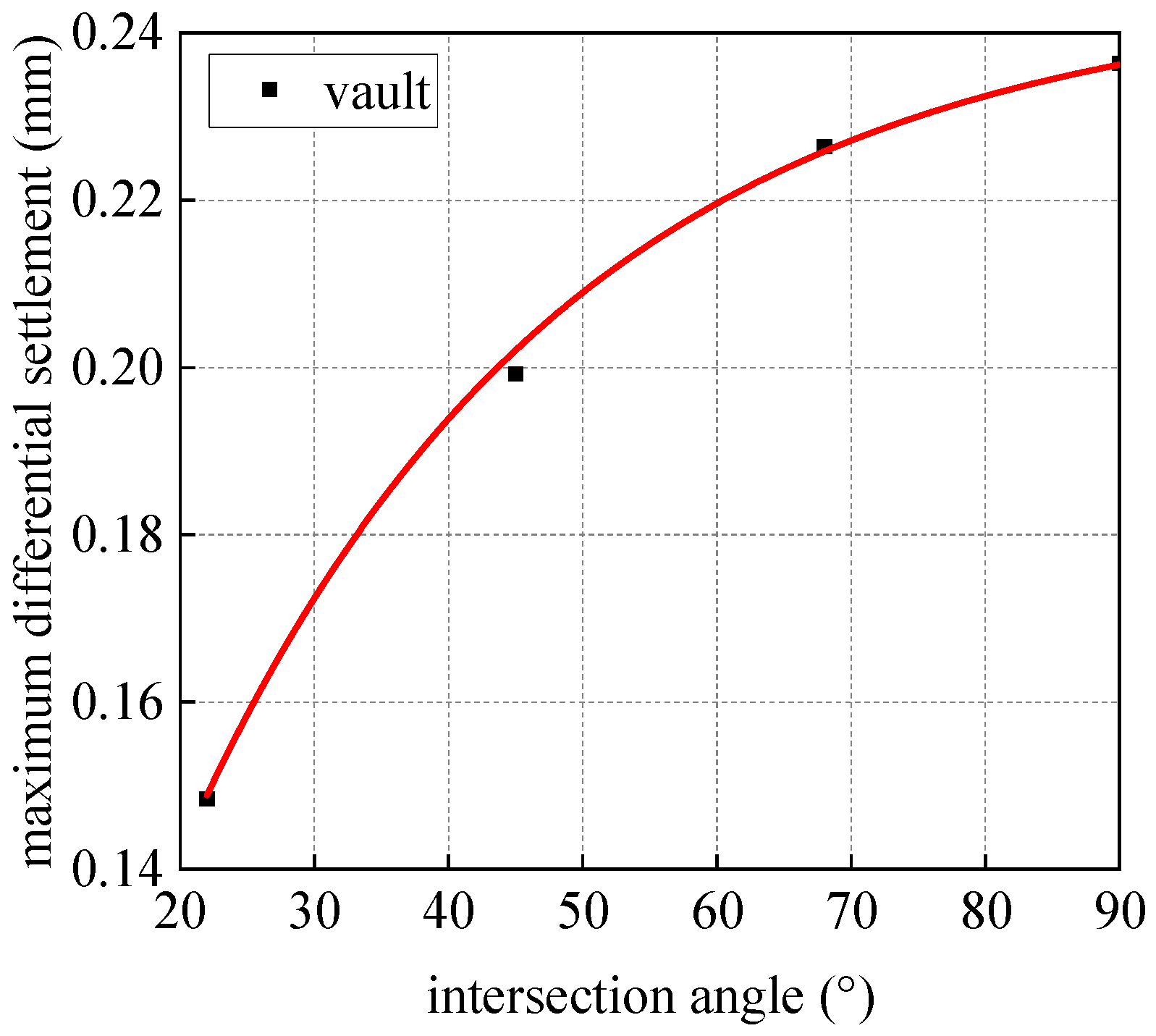
4.2.2. Differential Settlement of Shield Segments

Figure 18 depicts the differential settlement curves recorded between segments of a shield tunnel at various intersection angles, and the data reveal that the shield segments situated within 10 m of the crossing center experience significant disturbances. Importantly, as the angle between the pipe and the shield tunnel increases, there is a corresponding escalation in the maximum differential settlement between the shield tunnel segments. This phenomenon can be primarily ascribed to the fact that a greater angle leads to a more concentrated unloading effect on the shield tunnel, particularly within a 5 m radius from the crossing center; within this range, the variation in additional unloading stress between the segments becomes more pronounced, thereby contributing to the observed increase in maximum differential settlement between the segments. Figure 19 illustrates the relationship between the maximum differential settlement of shield tunnel segments and varying intersection angles; the data presented in the figure indicate that as the intersection angle increases the differential settlement at the vault between adjacent segments exhibits a parabolic increase. Specifically, at an intersection angle of 22°, the maximum differential settlement is measured at 0.145 mm. As the angle increases from 22° to 45°, 68°, and ultimately 90°, the maximum differential settlement escalates by 34.21%, 52.55%, and 64.1%, respectively. It is noteworthy that when the intersection angle exceeds 68°, the differential settlement among the existing shield tunnel segments becomes markedly pronounced, reaching its peak at the maximum angle of 90°.
In summary, an increase in the angle between the pipe and the shield tunnel results in a reduction in vertical deformation within the shield tunnel. Conversely, this increase in angle leads to an escalation in the differential settlement among the segments. To mitigate the effects of longitudinal deformation of the segments and differential settlement between them, it is advisable in practical engineering applications to intersect existing shield tunnels at angles ranging from 45° to 68° during the pipe jacking construction process. The spatial configuration of the launch shaft and the receiving shaft determines the angular relationship between the two structures. Therefore, it is essential to carefully consider the placement of both the launch shaft and the receiving shaft in accordance with site limitations.

4.3. Different Vertical Clearances Between Pipes and Shield Tunnels

This study aims to analyze and compare the impact of different vertical spacings in pipe jacking construction on the structural deformation of shield tunnels. It employs a case study involving a subway shield tunnel that passes through a gravel layer (geotechnical investigation data can be found in Section 3.2). The pipe jacking is conducted perpendicularly to the shield tunnel. Four operational scenarios are defined, with the clearances between the newly constructed pipe jacking channel and the tunnel set at 4.4 m, 3.4 m, 2.4 m, and 1.4 m, respectively.

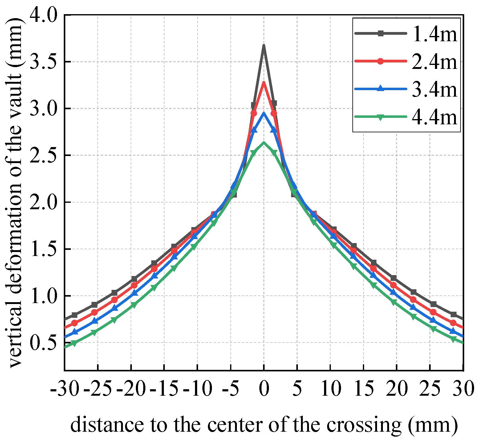
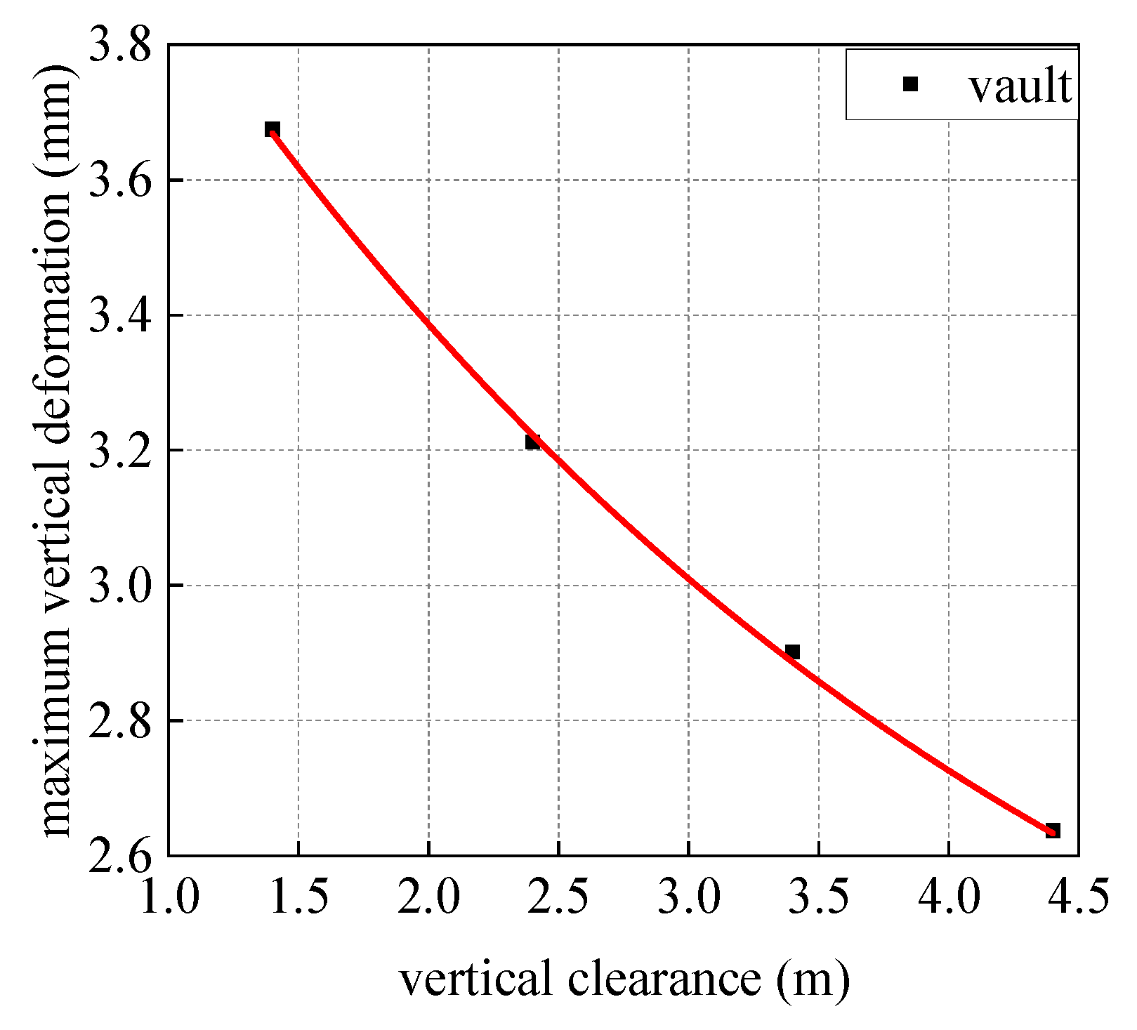
4.3.1. Longitudinal Deformation of Shield Segments

Figure 20 presents vertical displacement cloud diagrams depicting the surrounding soil adjacent to the shield tunnels at varying clearances. The data indicate that a reduction in clearance results in a significant impact on the interlayer soil located between the pipe jacking and the shield tunnel. Figure 21 presents the deformation curves of the shield tunnel structure in the longitudinal direction at varying clearances post-construction, and the data reveal that the shield tunnel structure exhibits a “V”-shaped vertical deformation across the different clearances. Notably, as the clearance between the pipe and the shield tunnel decreases, there is a corresponding increase in the vertical deformation of the tunnel’s vault. It is because reduced clearances lead to heightened additional stress on the shield tunnel structure due to the excavation, thereby resulting in an escalation of the longitudinal deformation of the shield tunnel. Figure 22 depicts the maximum deformation curve of the shield tunnel structure across different clearances, and the data demonstrate that as the clearance between the pipe and the tunnel decreases, the vertical deformation of the existing shield tunnel vault exhibits a parabolic increase. Notably, at a clearance of 4.4 m, the maximum vertical deformation of the vault is measured at 2.63 mm. As the clearance is reduced from 4.4 m to 3.4 m, 2.4 m, and 1.4 m, the maximum vertical deformation of the vault increases by 10.03%, 21.82%, and 39.36%, respectively.
The findings suggest that when the separation between the pipe and the shield tunnel is less than 2.4 m—equivalent to the diameter of the pipe employed in this study—there is a notable increase in the vertical deformation of the existing shield tunnel.

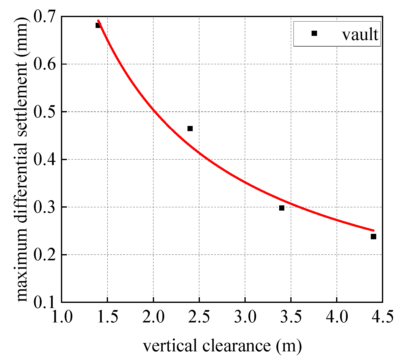
4.3.2. Differential Settlement of Shield Segments

Figure 23 presents the differential settlement curves for the segments of the shield tunnel at varying clearances. The maximum differential deformation recorded at these clearances occurs within a 5 m radius from the center of the crossing. As the clearance between the pipe and the shield tunnel decreases, there is a corresponding increase in the differential settlement between the segments of the shield tunnel. This phenomenon can be explained by the fact that, at reduced clearances, the additional unloading stress experienced by the shield tunnel structure intensifies, and the variation in this additional unloading stress along the segments becomes more pronounced, leading to a significant increase in the differential settlement between the shield segments. Figure 24 presents the maximum differential settlement curves for shield tunnel segments at various vertical clearances, and the data reveal that a reduction in vertical clearance correlates with a parabolic increase in the maximum differential settlement. Notably, at a spacing of 4.4 m, the maximum differential settlement at the vault is recorded at 0.238 mm. As the spacing decreases to 3.4 m, 2.4 m, and 1.4 m, the maximum differential settlement at the vault increases by 25.23%, 95.21%, and 186.21%, respectively. These results indicate that when the spacing between the pipe and the shield tunnel falls below 2.4 m (the diameter of a single pipe segment), the increase in differential settlement of the existing shield tunnel becomes significantly pronounced.
In summary, as the proximity between the pipe and the shield tunnel decreases, there is a notable increase in both the longitudinal deformation of the shield tunnel structure and the differential settlement of its segments. Therefore, it is essential to carefully manage the spacing between the pipe and the shield tunnel throughout the construction process. For the pipe utilized in this project, it is recommended that the spacing between the pipe and the shield tunnel be greater than 2.4 m (the diameter of the pipe segments used in this project). If site restrictions and other conditions are satisfied, the correction system of the pipe jacking machine can be calibrated to elevate the head of the machine prior to its arrival at the shield tunnel. This adjustment effectively increases the vertical clearance between the pipe jacking apparatus and the shield tunnel during the crossing phase.

5. Conclusions

This article presents an analysis of a pipe jacking project that intersects with Metro Line 6 in Chengdu. The study employs both on-site monitoring and numerical simulation techniques to thoroughly examine the effects of the geological strata surrounding the existing shield tunnel, as well as the spatial relationship between the pipe jacking operation and the shield tunnel; on the segments of the shield tunnel, it can serve as a valuable reference for the safeguarding of existing shield tunnels in analogous projects. The findings reveal that the following:
(1)
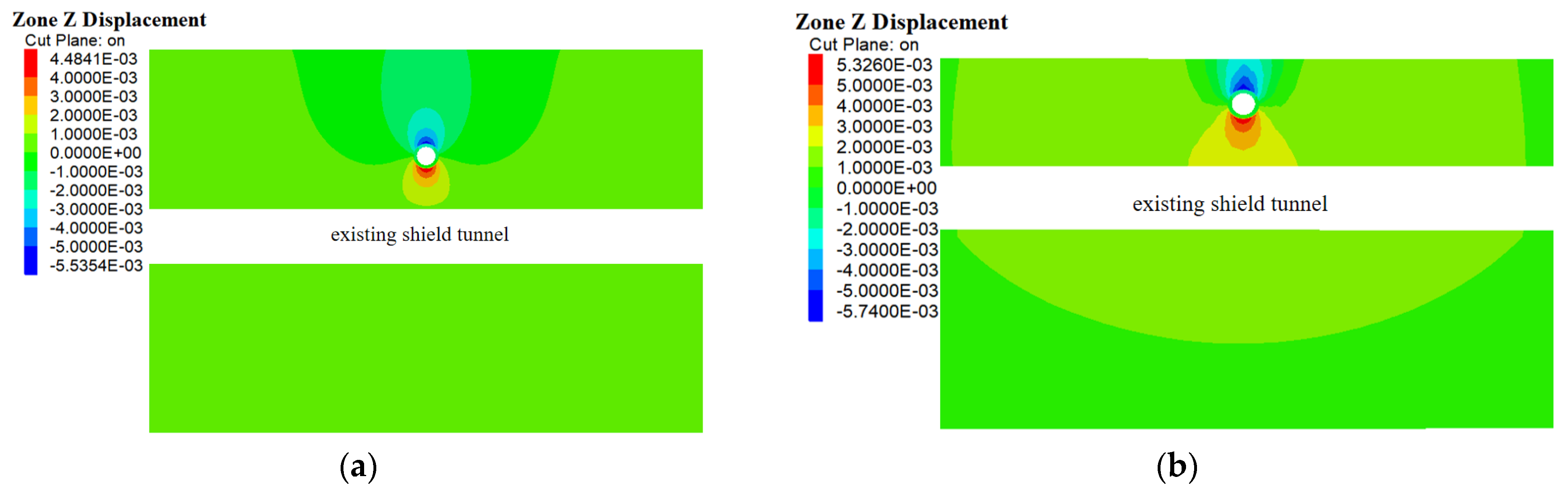
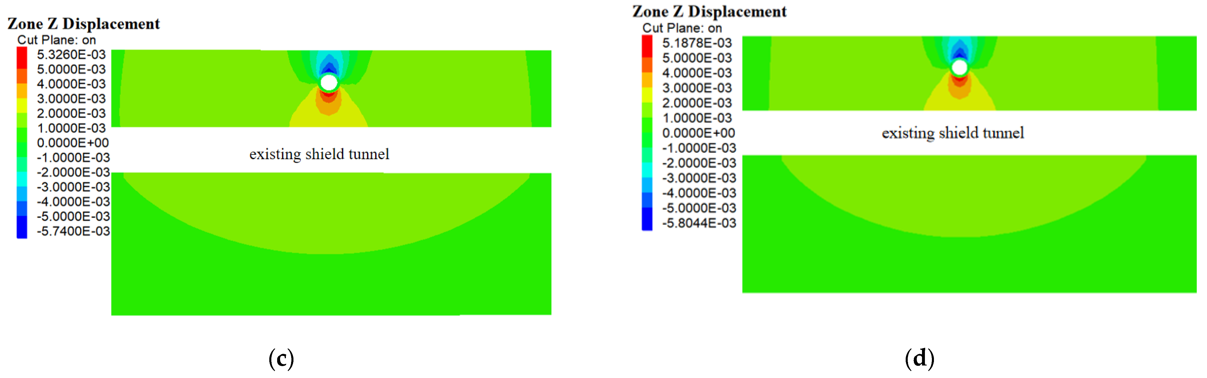
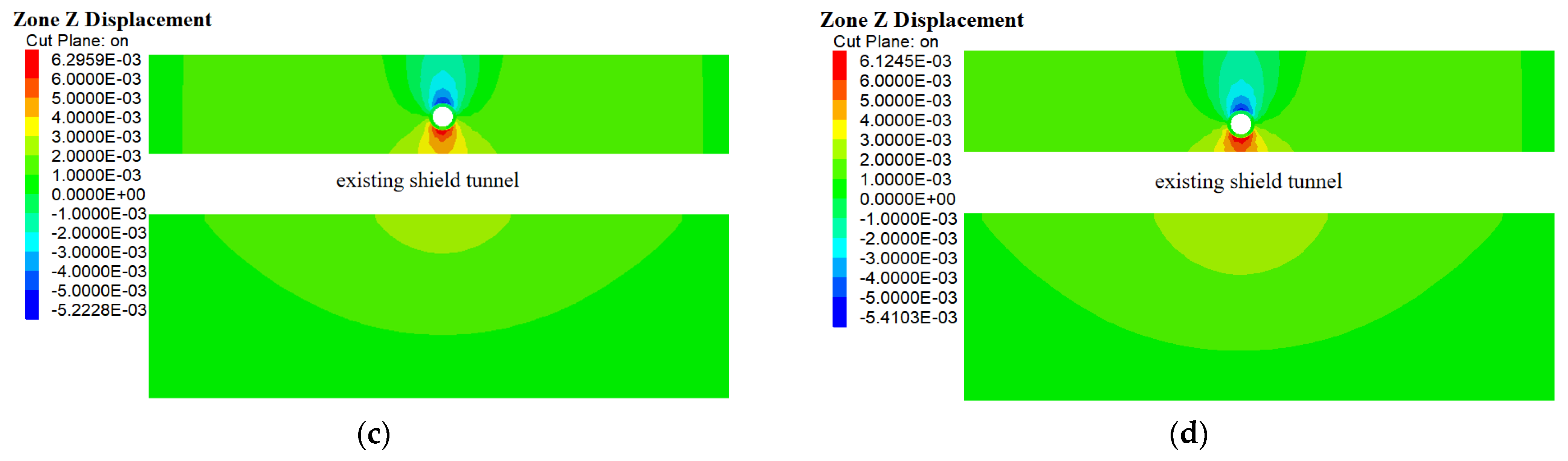
The disruption of the existing shield tunnel primarily takes place following the passage of the pipe through the shield tunnel. The most significant disturbance is observed at the tunnel cross-section located directly beneath the newly constructed segment of the jacking pipe. The existing shield tunnel exhibits both “V”-shaped vertical deformation and horizontal deformation.
(2)
Maintaining a consistent clearance and angle in relation to the jacking pipe, the longitudinal deformation recorded in the shield tunnel in the gravel layer is significantly more pronounced than that in the moderately weathered mudstone layer. The peak vertical deformation at the vault reaches 2.67 mm, which is approximately tenfold greater than the deformation noted in the shield tunnel situated in the moderately weathered mudstone layer. Therefore, it is essential to prioritize the protection of shield tunnels located in soils with a low deformation modulus and low cohesion. In practical engineering contexts, methods such as grouting can be utilized to improve the stability of the interlayer soil, thereby reducing disturbances to the existing shield tunnels.
(3)
As the angle between the pipe and the shield tunnel increases, there is a significant reduction in the vertical deformation of the shield tunnel; however, the differential settlement between the segments tends to increase. Specifically, when the angle is raised from 45° to 68°, the maximum vertical deformation at the vault is notably reduced by 4.97%. In contrast, the increase in the maximum differential settlement between the segments is relatively modest, at 13.66%. To mitigate the effects of longitudinal deformation of the segments and differential settlement between them, it is advisable in practical engineering applications to intersect shield tunnels at angles ranging from 45° to 68°. Therefore, it is essential to carefully consider the placement of both the launch shaft and the receiving shaft in accordance with site limitations.
(4)
As the vertical clearance between the pipe and the shield tunnel decreases, both the longitudinal settlement of the tunnel structure and the differential deformation of the pipe segments exhibit a parabolic escalation. In particular, when the separation between the pipe and the shield tunnel is reduced from 2.4 m (which corresponds to one pipe diameter) to 1.4 m, there is a notable increase in the maximum vertical deformation at the vault and the differential settlement among the pipe segments, with increases of 14.40% and 46.6%, respectively. Therefore, in the domain of practical engineering, it is advisable to maintain a clearance greater than one pipe diameter during the construction of the pipe over the subway shield tunnel. It is feasible to enhance the clearances by proactively modifying the pipe jacking correction system, contingent upon compliance with site-specific constraints.
This article offers an analysis of the deformation mechanisms associated with shield tunnels during the pipe jacking process; however, several limitations warrant consideration. The study is predicated on typical geological strata found in the Chengdu region and does not account for the potential influence of strata from other areas. In order to streamline the numerical model, several assumptions were made, including the characterization of soil layers as isotropic elastic-plastic materials, which may not adequately reflect the complexities inherent in real-world conditions. Additionally, field variability, such as fluctuations in groundwater levels, may also impact the findings. Future investigations should aim to integrate more extensive field data and take into account the aforementioned factors to enhance the model’s accuracy.

Author Contributions

Conceptualization, L.L.; Methodology, Q.Z. and F.W.; Software, Q.Z.; Validation, Q.Z. and F.W.; Formal analysis, Y.F.; Investigation, Y.F.; Resources, F.W.; Data curation, W.L.; Visualization, Y.F.; Supervision, Q.Z. and W.L.; Project administration, W.L. and F.W. All authors have read and agreed to the published version of the manuscript.

Funding

This research was funded by the Metallurgical Corporation of China Ltd., grant number Major R&D Projects of MCC (MCC Tech [2023] No.5-5).

Data Availability Statement

The original contributions presented in this study are included in the article. Further inquiries can be directed to the corresponding author.

Conflicts of Interest

Authors Li Luo and Weihua Liu were employed by China MCC5 Group Corp., Ltd. The remaining authors declare that the research was conducted in the absence of any commercial or financial relationships that could be construed as a potential conflict of interest.

References

  1. Deng, Z.; Liang, N.; Liu, X.; De La Fuente, A.; Lin, P.; Peng, H. Analysis and Application of Friction Calculation Model for Long-clearance Rock Pipe Jacking Engineering. Tunn. Undergr. Space Technol. 2021, 115, 104063. [Google Scholar] [CrossRef]
  2. Lehmann, G.; Käsling, H.; Cambier, A.; Praetorius, S.; Thuro, K. Performance Analysis of Utility Tunneling Data: A Case Study of Pipe Jacking in Hard Rock in Brittany, France. Tunn. Undergr. Space Technol. 2022, 127, 104574. [Google Scholar] [CrossRef]
  3. Li, Y.; Liu, G.; Liu, J.; Huang, J.; Tian, F.; Liu, F. Case Study on the Large Diameter Pipe Jacking for Utility Tunnel. Staveb. Obz. Civ. Eng. J. 2023, 32, 70–82. [Google Scholar] [CrossRef]
  4. Zhang, P.; Zhang, Y.; Ariaratnam, S.T.; Ma, B.; Zeng, C.; Liu, K. Field Monitoring and Analysis of Soil Deformation of Curved Steel Pipe Jacking in Gongbei Tunnel. Tunn. Undergr. Space Technol. 2023, 138, 105153. [Google Scholar] [CrossRef]
  5. Qi, Z.; Liu, J.; Gong, K. The Impact of Pipe Jacking Method Entrance and Exit Construction on the Surrounding Environment. IOP Conf. Ser. Earth Environ. Sci 2021, 634, 12103. [Google Scholar] [CrossRef]
  6. Li, Z.; Weng, X.; Cui, Y. Study on the Influence of Pipe Jacking Construction on Existing Subway Tunnels. Environ. Earth Sci. 2024, 83, 651. [Google Scholar] [CrossRef]
  7. Liu, W.; Wu, Y.; Zhao, H.; Xu, X.; Miao, L. Deformations of Subway Tunnels Induced by the Overcrossing Jacked Box Tunnels. Symmetry 2021, 13, 1800. [Google Scholar] [CrossRef]
  8. Xu, X.; Tong, L.; Li, Z.; Liu, X.; Hu, Q.; Yao, H.; Li, J. Influence of Extreme Shallow Jacked Box Tunnelling on Underlying Metro Tunnels: A Case Study. Undergr. Space 2023, 12, 234–250. [Google Scholar] [CrossRef]
  9. He, Q. Analysis of Influence Due to Pipe Jacking Traversing Subway Tunnel. Ind. Constr. 2011, 41, 821–823, 857. [Google Scholar] [CrossRef]
  10. Liu, X.; Wang, L.; Zhou, X.; Wang, J.; Zhong, Z.; Liu, P.; Xiong, F.; He, C. E-M Calculation Model and Its Application of Calculating Deformation in a New Tunnel Orthogonally Undercrossing an Existing Tunnel. Tunn. Undergr. Space Technol. 2022, 123, 104418. [Google Scholar] [CrossRef]
  11. Ren, D.-J.; Xu, Y.-S.; Shen, J.S.; Zhou, A.; Arulrajah, A. Prediction of Ground Deformation during Pipe-Jacking Considering Multiple Factors. Appl. Sci. 2018, 8, 1051. [Google Scholar] [CrossRef]
  12. Zhang, X.; Li, L.; Xu, Y.; Meng, Y. Mathematical Modelling for Strata Deformation Caused by Rectangular Pipe Jacking Construction in Composite Layered Ground. Appl. Math. Model. 2024, 136, 115649. [Google Scholar] [CrossRef]
  13. Chen-jie, L.; Bo, L.; Cong-an, L.; Zhi-peng, W. Centrifuge Model Test of the Influence of Tunnel Excavation with Different Spacings on Existing Tunnels. IOP Conf. Ser. Earth Environ. Sci 2024, 1333, 12032. [Google Scholar] [CrossRef]
  14. Fang, Q.; Liu, X.; Zeng, K.; Zhang, X.; Zhou, M.; Du, J. Centrifuge Modelling of Tunnelling below Existing Twin Tunnels with Different Types of Support. Undergr. Space 2022, 7, 1125–1138. [Google Scholar] [CrossRef]
  15. Guo, H.; Zhang, G.; Mao, X.; Zan, J. A Novel Simplified Physical Model Testing Method for Ground Settlement Induced by Shield Tunnel Excavation. Buildings 2025, 15, 710. [Google Scholar] [CrossRef]
  16. Tang, J.; Xu, J.; Zhou, D.; Huang, D.; Zeng, K.; Li, Y.; Chen, Z. Ground Surface Deformation Caused by Pipe Jacking Construction in a Soft Soil Area: An Experiment-Based Study. Buildings 2023, 13, 1628. [Google Scholar] [CrossRef]
  17. Li, Z.; Chen, Z.; Yang, Y.; Jiang, Y.; Xu, X.; Hu, Q. Deformation Characteristics of Existing Tunnels Induced by Above-Crossing Quasi-Rectangular Shield Tunnel. Transp. Geotech. 2024, 45, 101227. [Google Scholar] [CrossRef]
  18. Shao, G.; Yang, N.; Han, J. Study on the Deformation Induced by Vertical Two-Layer Large Diameter Pipe-Jacking in the Soil-Rock Composite Stratum. Appl. Sci. 2022, 12, 12780. [Google Scholar] [CrossRef]
  19. Yang, X.; Liu, Y.; Yang, C. Research on the Slurry for Long-clearance Large-diameter Pipe Jacking in Expansive Soil. Adv. Civ. Eng. 2018, 2018, 9040471. [Google Scholar] [CrossRef]
  20. Zhang, S.; Xu, X.; Luo, F.; Shi, T.; Xu, T.; Zhang, P. Field Test and Numerical Simulation Study on Pipe Sticking of Pipe Jacking in Composite Stratum. Buildings 2024, 14, 3992. [Google Scholar] [CrossRef]
  21. Xie, C.; Qu, Y.; Lu, H.; Song, S. Study on Deformation of New Tunnels Overcrossing Existing Tunnels underneath Operating Railways. Buildings 2024, 14, 2420. [Google Scholar] [CrossRef]
  22. Ye, P.; Lan, B.; Zhang, P.; Zeng, C.; Xu, T.; Xu, Y.; Wu, R. Numerical Simulation Study on Evolution Process of Carrying-Soil Effect of Rectangular Pipe Jacking. Buildings 2024, 14, 3057. [Google Scholar] [CrossRef]
  23. Zhang, J.; Yu, J.; Li, C.; Liu, Y.; Tian, L.; He, Y.; Zhang, Q. Deformation and Reinforcement of the Existing Tunnel Affected by New Shield Tunnel Construction with Small Clearance. Buildings 2025, 15, 265. [Google Scholar] [CrossRef]
  24. Wei, G.; Yang, B.; Zhang, X.; Wu, H. Research on Longitudinal Deformation of Existing Shield Tunnel Caused by Shield Tunneling. Chin. J. Undergr. Space Eng. 2020, 16, 1754–1762, 1808. [Google Scholar]
  25. Yu, D.; Li, Z.; Liang, R. Coupling Analysis of Longitudinal Deformation of Shield Tunnel Caused by Overcrossing Tunneling in Layered Soils. Tunn. Constr. 2023, 43, 804–815. [Google Scholar]
  26. Xu, Y.; Du, Y. Analysis of Longitudinal Deformation of Existing Tunnel Caused by Overpassing of New Shield Tunneling Based on Timoshenko-Pasternak Model. Technol. Highw. Transp. 2024, 40, 29–42. [Google Scholar]
  27. Zhang, B.; Xie, J.; Huang, X. Three Dimensional Numerical Analysis of the Interaction Mechanism between Shield Tunneling and Existing Double Track Tunnels. J. China Foreign Highw. 2023, 43, 247–252. [Google Scholar] [CrossRef]
  28. LI, Y.; Chen, S.; Zhou, Z. Study on Reasonable Clear clearance for a Shield Tunnel’s Excavation Closely Adjacent to a Shallowly-Buried Rectangular Tunnel. Railw. Stand. Des. 2014, 58, 80–83. [Google Scholar] [CrossRef]
  29. Wang, M.; Zhang, X.; Gou, M.; Cui, G. Method of Three-Dimensional Simulation for Shield Tunneling Process and Study of Adjacent Partition of Overlapped Segment. Rock Soil Mech. 2012, 33, 273–279. [Google Scholar] [CrossRef]
  30. Wen, S.; Zhang, M.; Zhou, Y.; Sheng, G. Reasonable Vertide Net clearance of Urban Rail Transit Double-Track Overlapping Shield Tunnels. Urban Mass Tranbit 2023, 26, 68–72. [Google Scholar] [CrossRef]
  31. Zhang, W.; Liu, H.; Hu, Y.; Liu, R.; Tan, Q.; Xie, N.; Ye, W. Deformation Control of Shield Short-clearance Crossing Existing Tunnels in Silt Reclamation Stratum. J. Railw. Eng. Soc. 2024, 41, 87–91. [Google Scholar]
  32. Jiang, Z.; Zhang, B.; Liu, S.; Wang, H.; Liu, Y. Influence of Large-Section Rectangular Pipe Jacking on Deformation of Existing Subway Tunnels. J. Eng. Geol. 2022, 30, 1703–1712. [Google Scholar]
  33. Ying, H.; Yao, Y.; Wang, K.; Zhang, C. Observed Environment Response Caused by Construction of Double-Line Parallel Pipe Jacking Crossing over Metro Shield Tunnels1. J. Shanghaijiaotong Univ. 2023, 57, 1639–1647. [Google Scholar] [CrossRef]
  34. He, H.; Wang, S.; Shen, W.; Zhang, W. The Influence of Pipe-Jacking Tunneling on Deformation of Existing Tunnels in Soft Soils and the Effectiveness of Protection Measures. Transp. Geotech. 2023, 42, 101061. [Google Scholar] [CrossRef]
  35. Xiao, D.; Zhang, S.; Hu, Z.; Yu, Y.; Yan, X. Research on the Influence of Construction of Large-section Rectangular Pipe Jacking on Adjacent Obliquely Intersected Existing Tunnel. Mod. Tunn. Technol. 2022, 59, 411–447. [Google Scholar] [CrossRef]
  36. Wang, Y. Analysis of influencing factors for subway construction in special soil layers based on FLAC3D. J. Liaoning Tech. Univ. (Nat. Sci.) 2024, 14, 179–186. [Google Scholar]
Figure 1. HRC2000 pipe jacking machine.
Buildings 15 01394 g001
Figure 2. Profile relationship diagram between the pipe jacking line and Metro Line 6.
Buildings 15 01394 g002
Figure 3. Schematic diagram of the intersection relationship between pipe jacking construction and the shield tunnel.
Buildings 15 01394 g003
Figure 4. Arrangement of measurement points.
Buildings 15 01394 g004
Figure 5. Cumulative displacement of different measurement points ((a) vertical displacement of measurement points 1, (b) horizontal displacement of measurement points 2).
Buildings 15 01394 g005
Figure 6. The longitudinal deformation trend of existing shield tunnels ((a) vertical displacement of monitoring points 1, (b) horizontal displacement of monitoring points 2).
Buildings 15 01394 g006
Figure 7. Numerical model.
Buildings 15 01394 g007
Figure 8. Deformation contour diagram of the existing shield tunnels ((a) vertical deformation, (b) horizontal deformation).
Buildings 15 01394 g008
Figure 9. Comparison of the measured values and the simulated values ((a) comparison of the measured values and the simulated values of measurement points 5, (b) comparison of the measured values and the simulated values of measurement points 1).
Buildings 15 01394 g009
Figure 10. Profile relationship diagram between the pipe jacking line and Metro Line 5.
Buildings 15 01394 g010
Figure 11. Vertical displacement cloud diagram of the surrounding soil of the shield tunnel in different strata ((a) moderately weathered mudstone stratum, (b) gravel stratum).
Buildings 15 01394 g011
Figure 12. Deformation of the shield tunnel along the longitudinal direction in different strata.
Buildings 15 01394 g012
Figure 13. Schematic diagram of differential settlement between shield tunnel segments.
Buildings 15 01394 g013
Figure 14. Differential settlement of the vaults between shield tunnel segments in different strata.
Buildings 15 01394 g014
Figure 15. Vertical displacement cloud diagram of the surrounding soil of the shield tunnel at different intersection angles ((a) 22°, (b) 45°, (c) 68°, (d) 90°).
Buildings 15 01394 g015aBuildings 15 01394 g015b
Figure 16. Comparison of the deformation of the shield tunnel along the longitudinal direction at different intersection angles.
Buildings 15 01394 g016
Figure 17. Maximum deformation of the shield tunnel at different intersection angles.
Buildings 15 01394 g017
Figure 18. Comparison of differential deformation of shield tunnel segments at different intersection angles.
Buildings 15 01394 g018
Figure 19. Maximum differential deformation of shield tunnel segments at different intersection angles.
Buildings 15 01394 g019
Figure 20. Vertical displacement cloud diagram of the surrounding soil of the shield tunnel at different clearances ((a) 4.4 m, (b) 3.4 m, (c) 2.4 m, (d) 1.4 m).
Buildings 15 01394 g020aBuildings 15 01394 g020b
Figure 21. Comparison of the deformation of the shield tunnel structure along the longitudinal direction at different clearances.
Buildings 15 01394 g021
Figure 22. Maximum deformation of the shield tunnel at different clearances.
Buildings 15 01394 g022
Figure 23. Comparison of differential deformation of shield tunnel segments at different clearances.
Buildings 15 01394 g023
Figure 24. Maximum differential deformation of shield tunnel segments at different net clearances.
Buildings 15 01394 g024
Table 1. Physical and mechanical properties of various materials in the model.
MaterialsUnit Weight
(kN/m3)
Young’s
Modulus
(MPa)
Poisson’s Ratio
(μ)
Friction (°)Cohesion
(kPa)
Thickness
(m)
miscellaneous fill17.5100.30108.04.6
slightly
dense
pebbles
21.0220.283107.1
moderately
weathered
mudstone
23.51400.253520028.3
pipes26.4835,5000.2--0.2
grouting
layer
18.010----
shield
segments
26.4835,5000.2--0.3
track bed20.004800.25 -
Table 2. Stratum parameters of Metro Line 5.
Soil
Layer
Unit Weight
(kN/m3)
Young’s
Modulus
(MPa)
Poisson’s Ratio
(μ)
Friction (°)Cohesion
(kPa)
Thickness
(m)
miscellaneous fill17.5100.30108.02.17
silty clay19.58.50.301825.04.91
slightly dense
pebbles
21.0180.283502.8
medium dense pebbles22.0280.254008.14
dense pebbles23.0540.2245013.01
Disclaimer/Publisher’s Note: The statements, opinions and data contained in all publications are solely those of the individual author(s) and contributor(s) and not of MDPI and/or the editor(s). MDPI and/or the editor(s) disclaim responsibility for any injury to people or property resulting from any ideas, methods, instructions or products referred to in the content.

