
Study on the Causes of Cracking in Concrete Components of a High-Pile Beam Plate Wharf


Abstract
1. Introduction
2. Characteristics of Cracks in Concrete Components
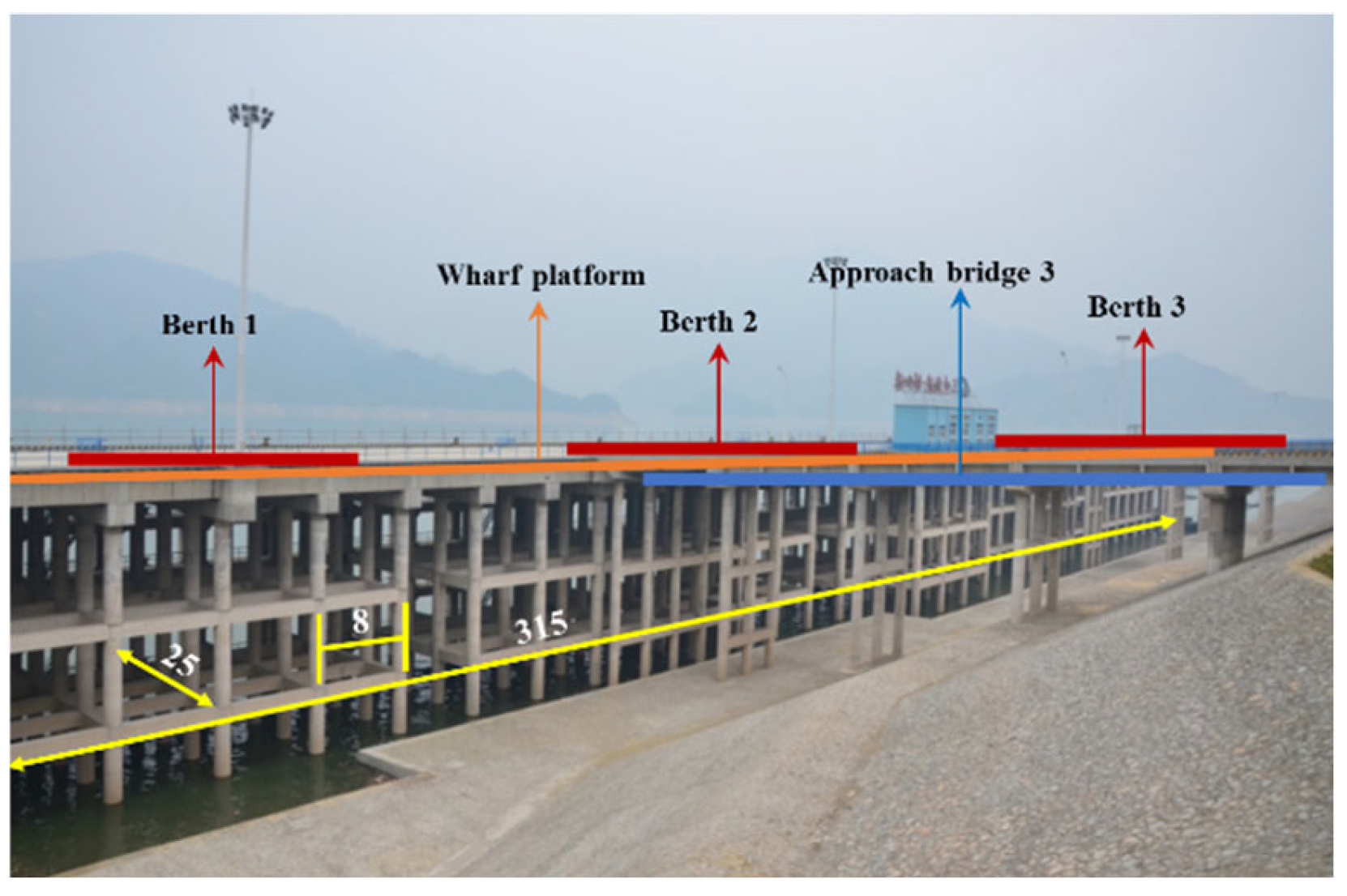
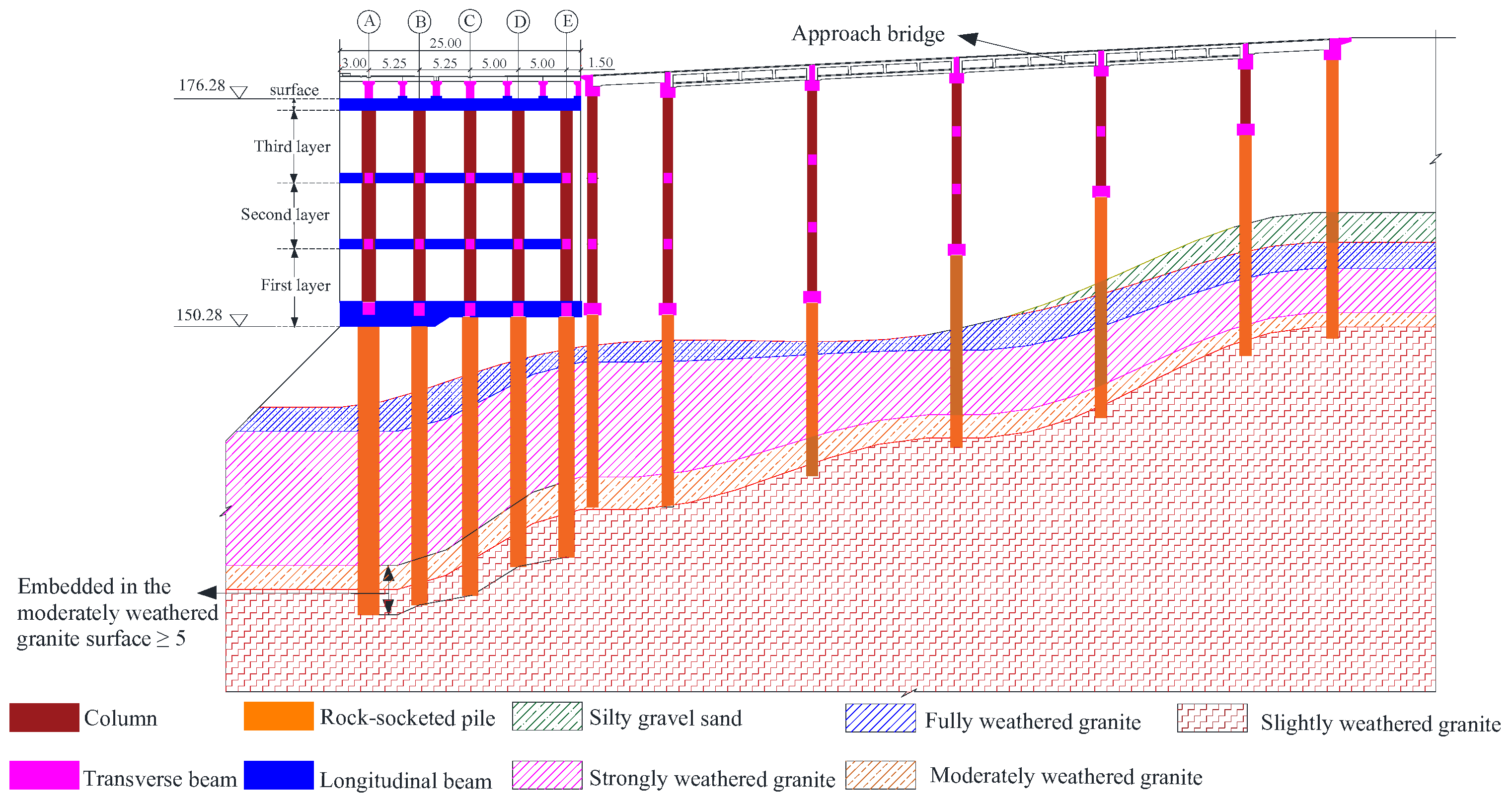
2.1. Project Overview
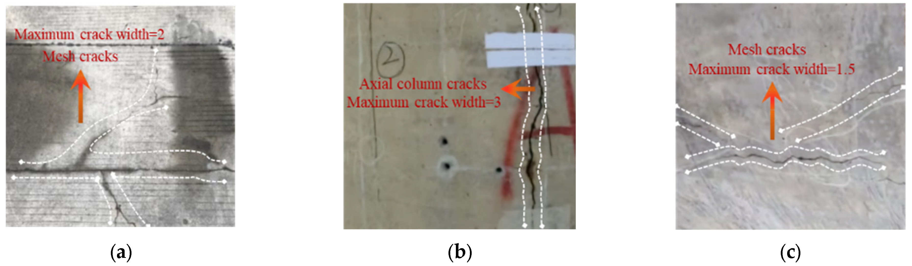
2.2. Characteristics of Cracks
3. Cause Investigation
3.1. Potential Causes
3.2. Cause Elimination
3.3. Exact Causes
4. Numerical Simulation
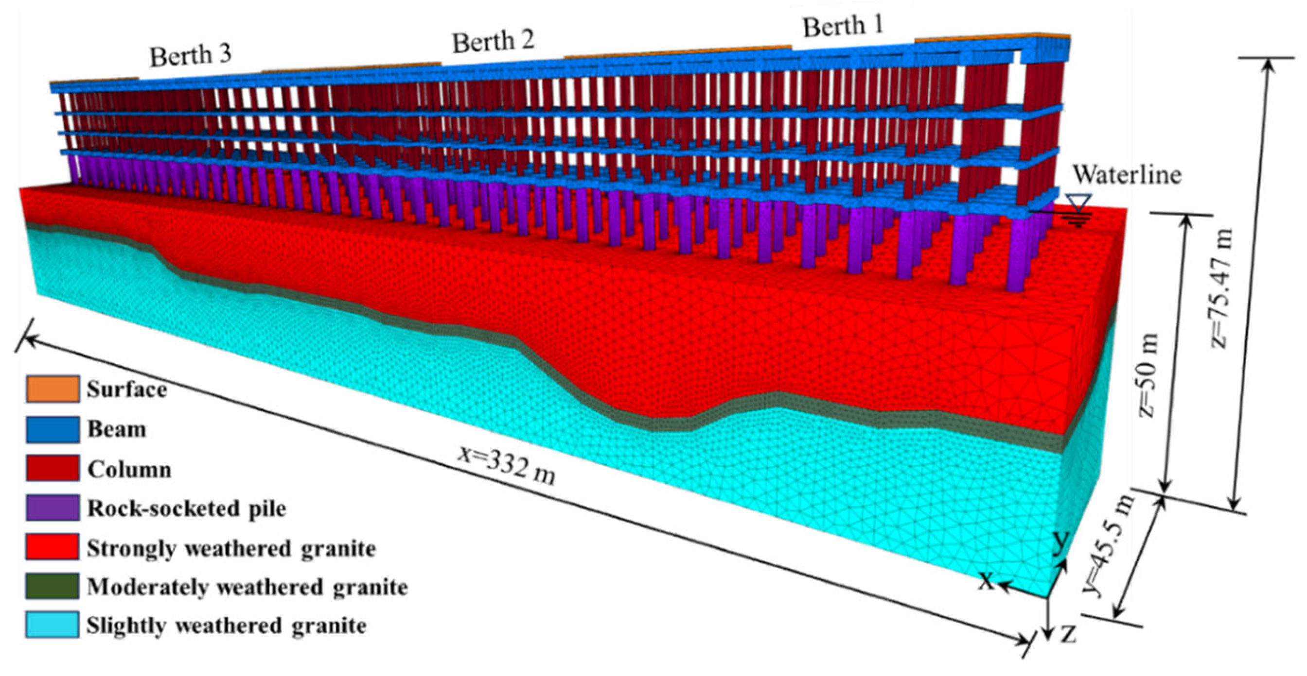
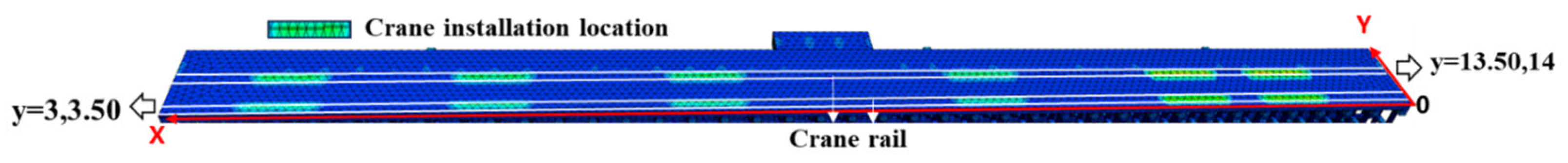
4.1. Numerical Model and Loading Cases
4.2. Simulation Results
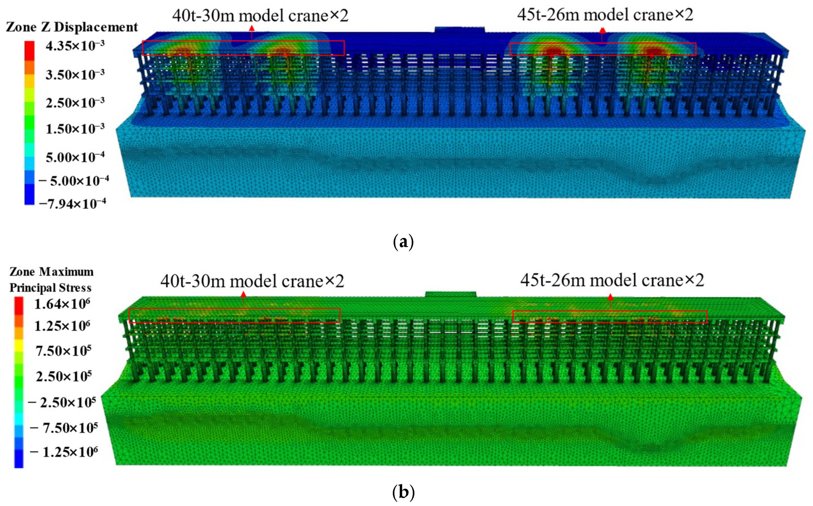
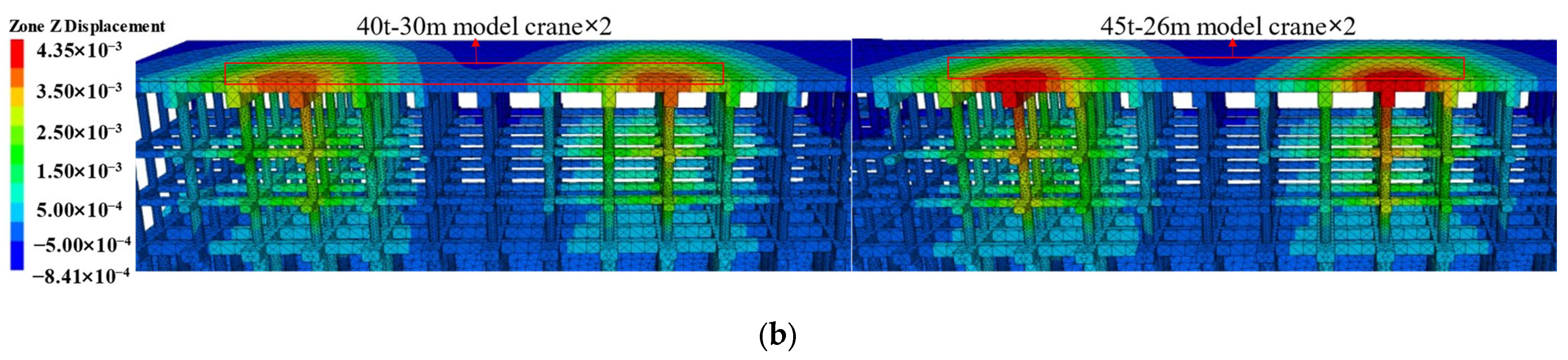
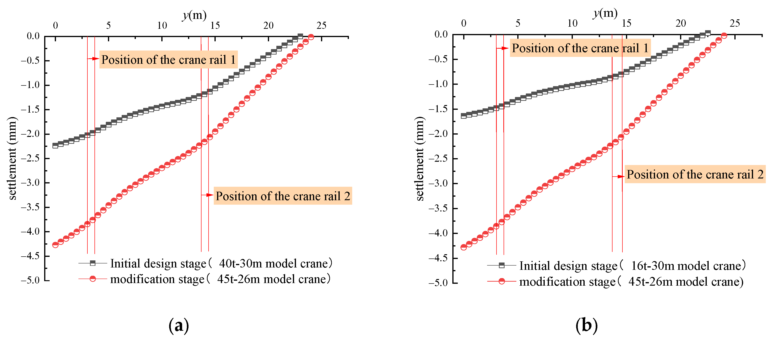
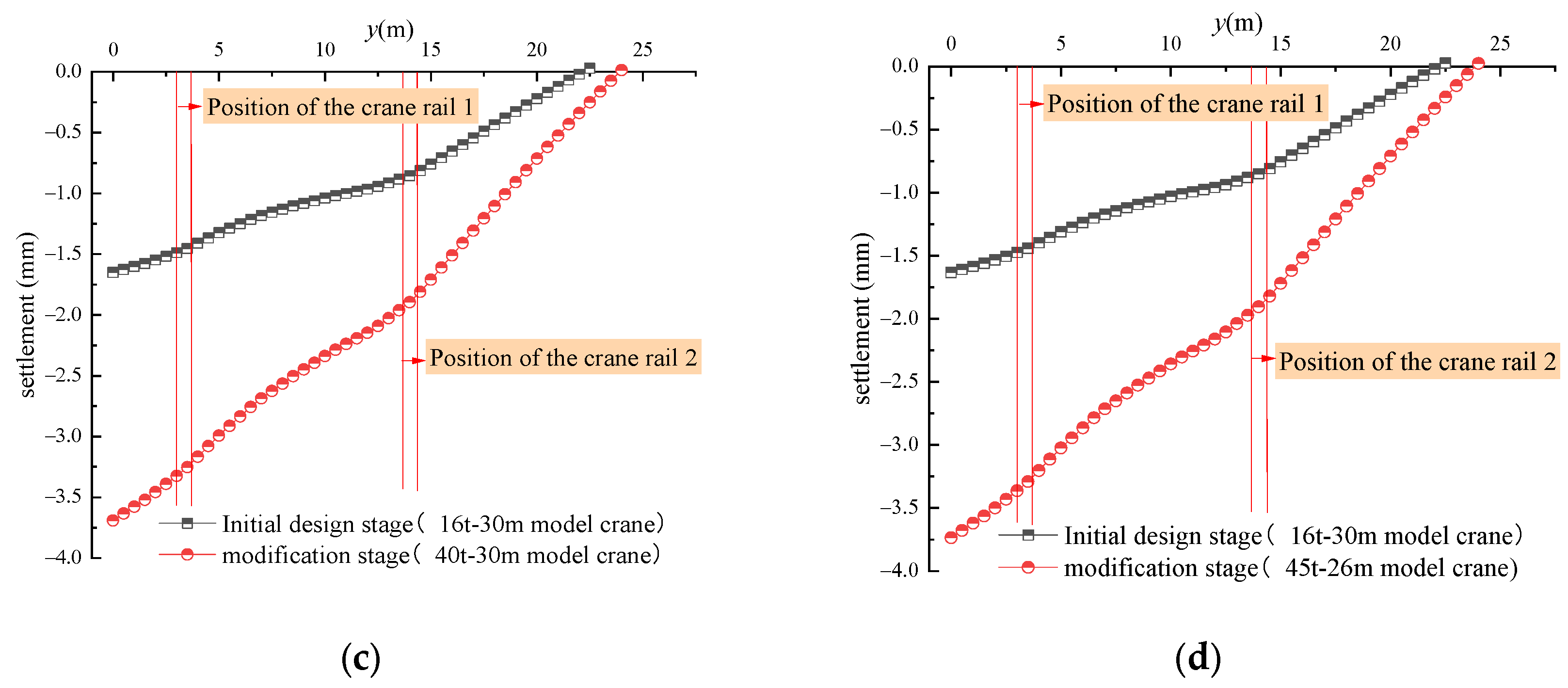
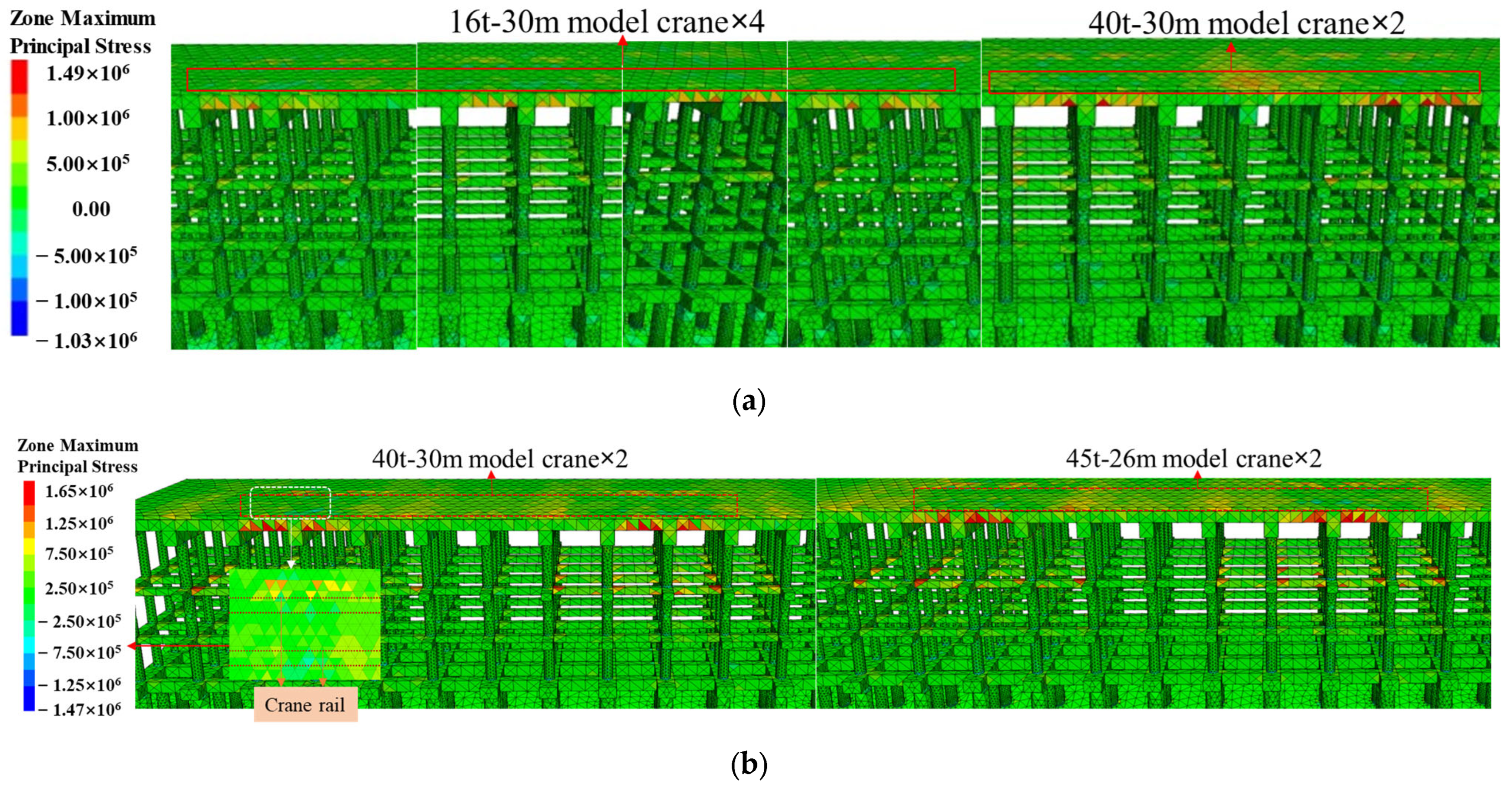
4.2.1. The Impact of Crane Changes
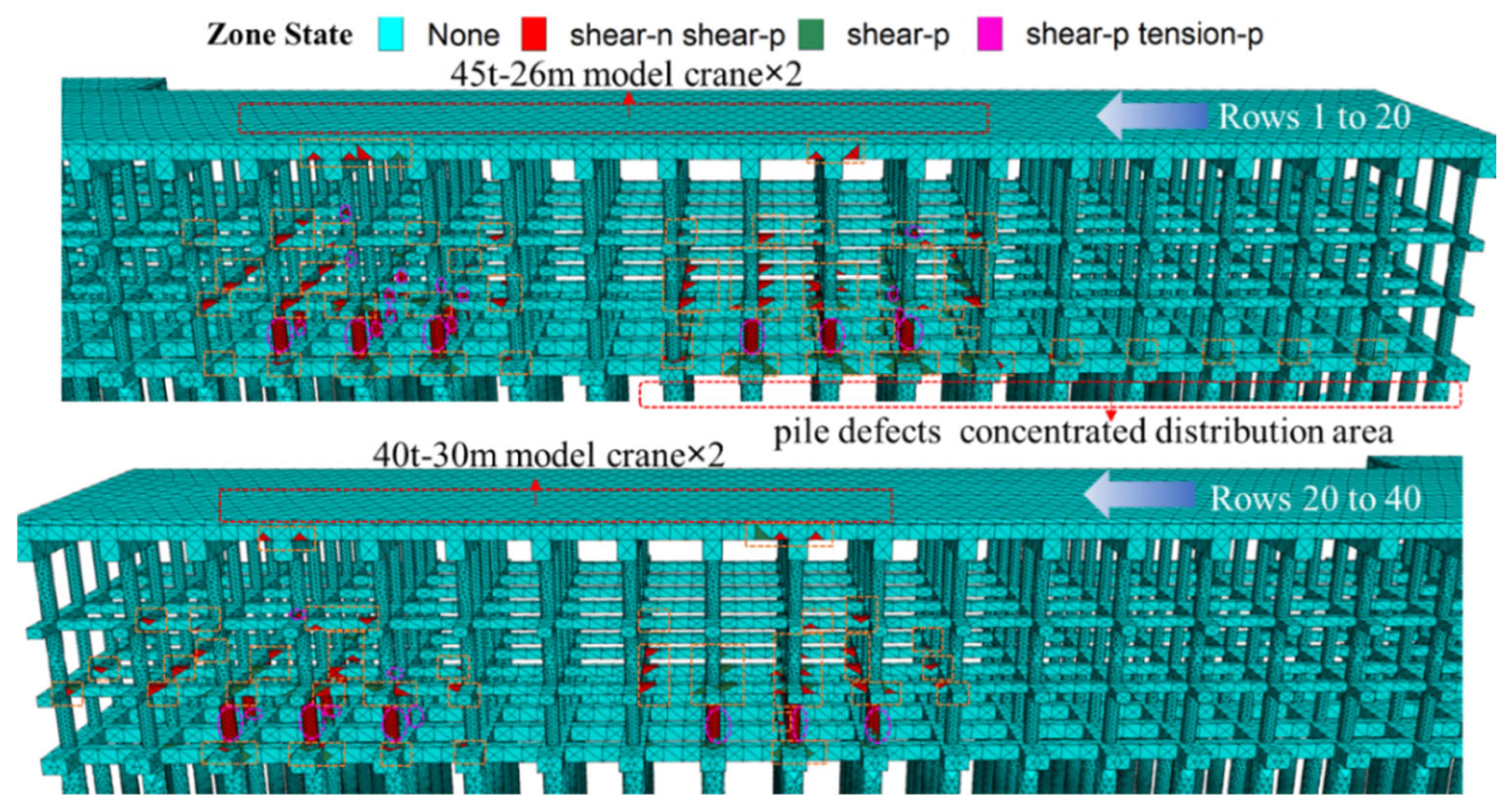
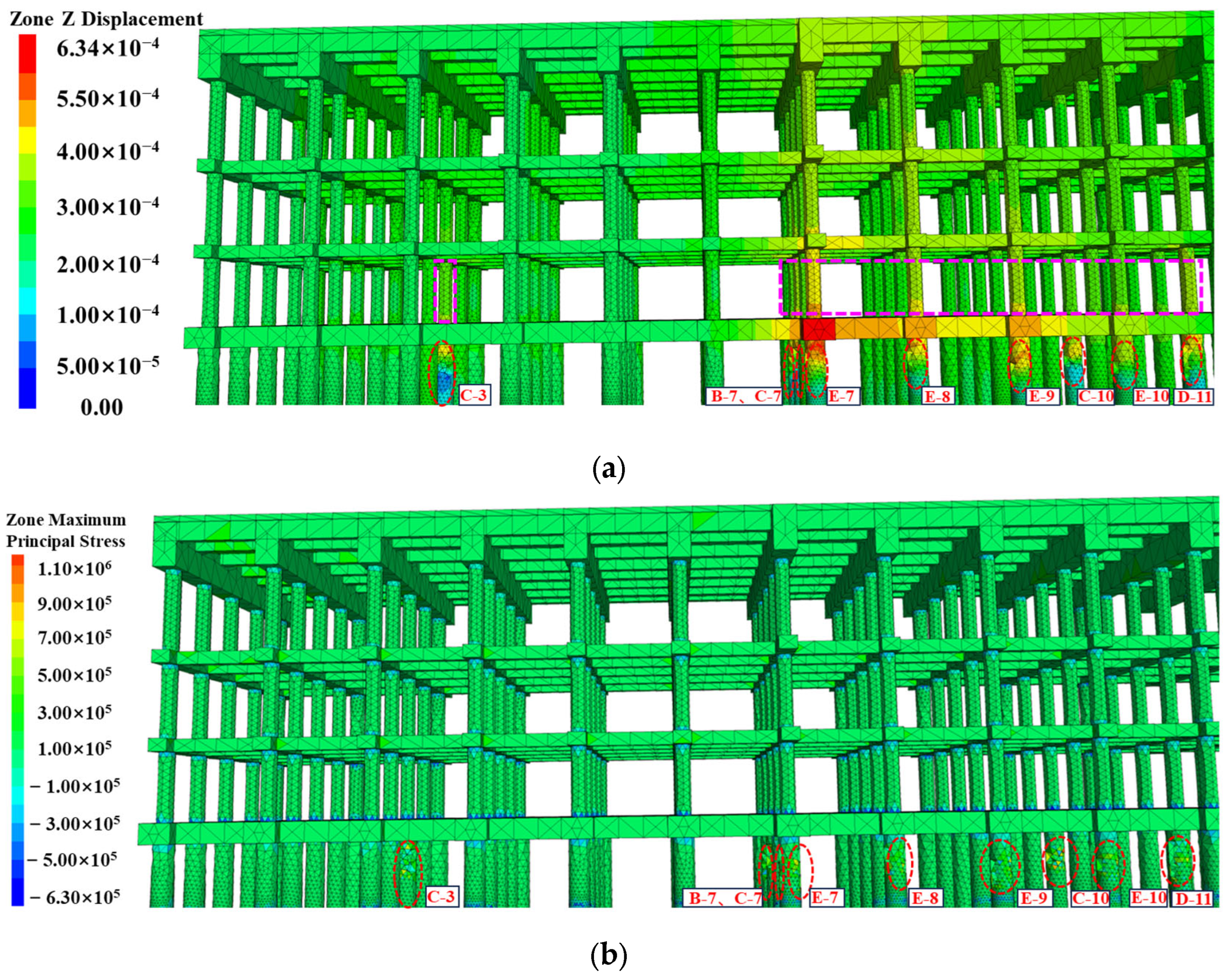
4.2.2. The Impact of Pile Defects
5. Treatment Measures
- It is necessary to repair and reinforce the concrete cracks existing on the wharf site. For the repair of shallow cracks or irregular cracking in concrete, it should be noted that these will not directly affect the structural load capacity. Cement, asphalt oil, and other similar materials can be applied directly to the surface of the concrete for repair. In cases where deep or penetrating cracks are more severe, grouting can be employed using pressure equipment to inject bonding materials into the cracks, thereby forming a unified whole and effectively improving the overall stability of the concrete. Distinct repair strategies should be implemented based on crack width. For cracks ≤0.2 mm, no intervention is typically required. Microcracks in concrete (0.2 < w ≤ 0.3 mm) may be treated using low-viscosity epoxy resin, which penetrates and solidifies within the fissures. Medium cracks (0.3–3 mm) necessitate high-pressure grouting with cementitious or polymeric materials, followed by surface sealing with elastomeric coatings. In cases where grouting is infeasible, structural reinforcement via steel mesh-reinforced shotcrete (C25 fine-aggregate concrete) is recommended. For cracks >3 mm, damaged concrete should be excavated and replaced with non-shrinkage, high-strength concrete to restore load-bearing capacity.
- Implement construction treatment in instances where the thickness of the steel reinforcement protective layer is not deemed to be adequate. In instances where the protective layer’s thickness is inadequate, remeasurement and reconstruction are necessary to augment the layer’s thickness and ensure compliance with the specified requirements. Conversely, in cases where the protective layer’s thickness is excessive, mechanical cleaning can be employed to eliminate the surplus layer. In instances where the steel reinforcement protection layer is not deemed to be of an acceptable standard, it is imperative to consider reconstruction in accordance with standard construction methods. Otherwise, it will reduce the bearing capacity of the wharf structure and accelerate the damage of the wharf structure.
- The lifting equipment is to be replaced in accordance with the actual requirements of the wharf. The installation method combining small and large lifting equipment in Case II is significantly more reasonable than the distribution of overly dense large lifting equipment in Case III. Furthermore, this method will not cause deformation or damage to the local structure of the wharf due to excessive load. Consequently, in order to guarantee the safe operation of the wharf, comprehensive selection, comparison, and optimization analysis of lifting equipment change plans must be conducted, and the most suitable lifting equipment installation plans must be selected for change processing.
- It is necessary to repair the defects in the piles and to adopt a new method for the daily testing of the pile foundations. This method should be capable of identifying damage to the pile foundation at an early stage and should enable timely measures for repair to be taken, thus avoiding greater losses.
- It is recommended that information technology be combined with the establishment of a wharf monitoring system to monitor the horizontal displacement and settlement deformation of hydraulic structures in real time. A wharf monitoring and early-warning system should be constructed to provide support and guarantee the construction and operation safety of emergency reinforcement and subsequent system reinforcement.
6. Conclusions
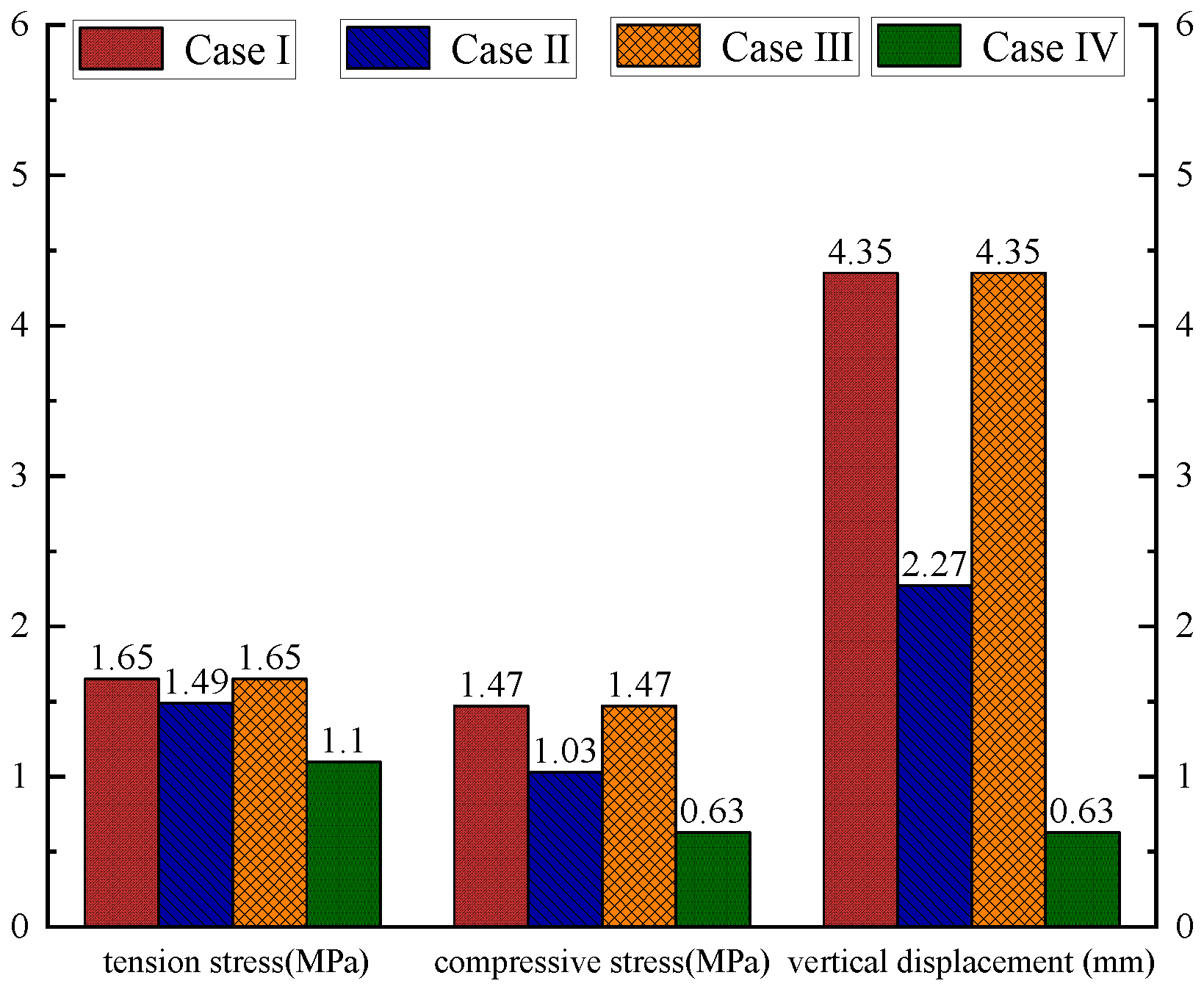
- The primary cause of the cracking observed in concrete components is the result of alterations made to the crane. Following the modification of the crane, the maximum tensile and compressive stresses of the wharf structure increased by 0.16 MPa and 2.58 MPa, respectively, in comparison to the initial design stage. This represents increases of 11% and 44%, respectively. This resulted in a maximum vertical displacement increase of 2.08 mm, representing a 92% increase. Furthermore, the maximum tensile stress generated by the crane following the modification exceeded the tensile strength of the concrete, leading to the formation of cracks.
- The impact of pile defects on the stability of wharf structures is relatively minor, yet it is nonetheless a significant factor that cannot be overlooked. The tensile stress at the defect site of the pile is high, with a maximum tensile stress of 1.1 MPa. This makes the defective pile prone to deformation and damage, thereby affecting the stability of the upper structure. The more intact pile resulted in greater deformation of the upper components of the defective pile, with a maximum vertical displacement increase of 0.23 mm, an increase of 58%.
- A three-dimensional numerical model of a high-pile beam plate wharf was constructed in order to ascertain the complex stress and deformation response of the structure under the combined action of gravity load, water load, crane load, and pile defects. Thus, an effective approach was provided. Given the multitude of factors that influence the safety of wharf structures in practice, it is highly effective and imperative to establish a comprehensive three-dimensional numerical model that aligns with the actual scale for analysis.
- In this paper, a large-scale three-dimensional numerical simulation was carried out by modeling according to the actual dimensions. It took into account the deformation and damage of the wharf under the combined action of multiple loads. The simulation results are consistent with the actual situation, which has great reference significance. However, regarding the accurate identification of the existing damage to the wharf structure, since the simulation did not consider the effects of wave loads, wind loads, or water erosion, there still exists a slight difference between the position of the plastic damage obtained from the numerical simulation and the actual damage position. As a result, it is unable to achieve the health monitoring of the wharf structure, and further research on this is still needed.
Author Contributions
Funding
Data Availability Statement
Conflicts of Interest
Abbreviations
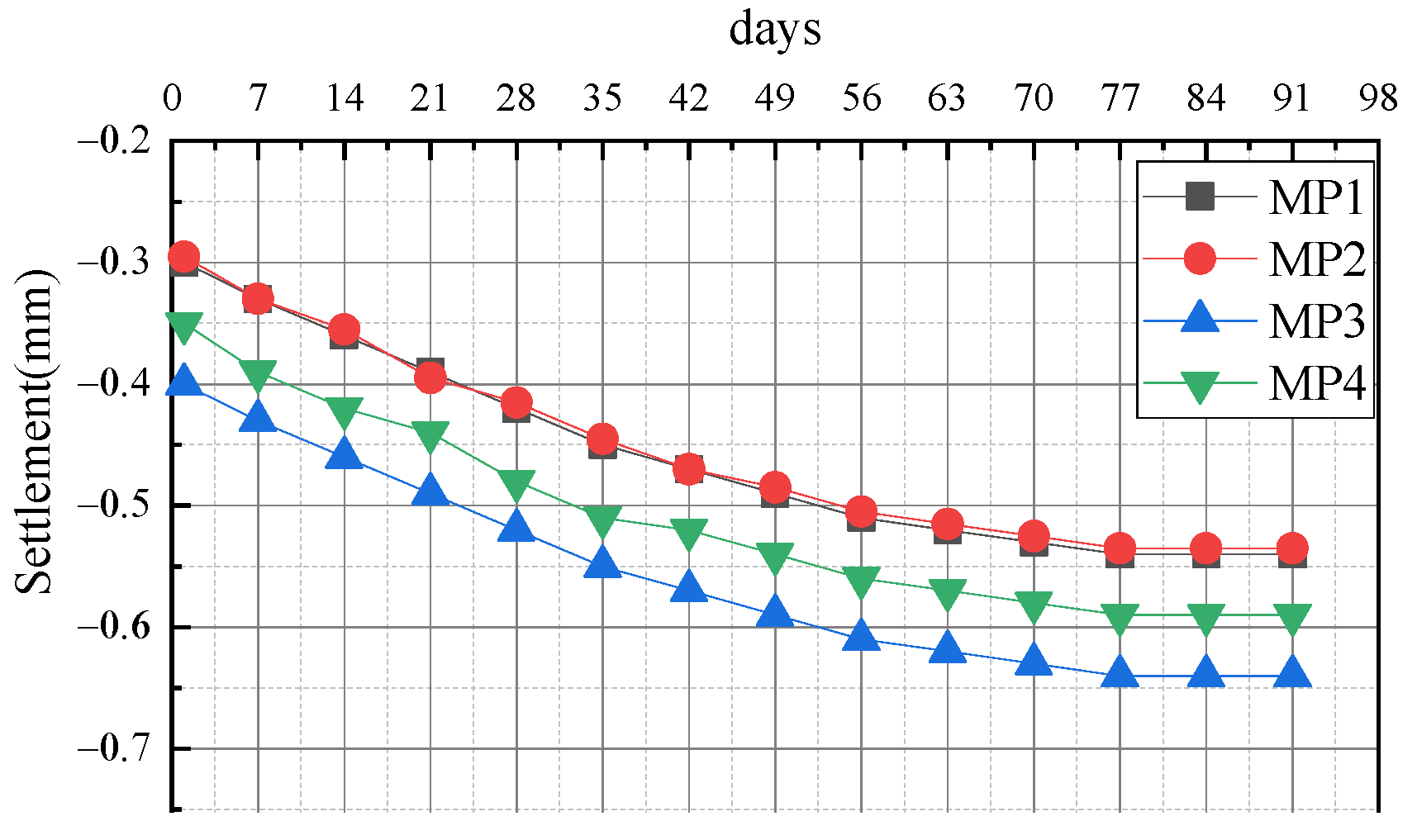
| MP | monitoring point |
References
- Su, J.B.; Yang, G.Q.; Zhang, L.M.; Zhu, R.H.; Qin, W.G. Safety Evaluation Method for High-Piled Wharf Structures Based on the Disturbing-Energy Method. Struct. Control Health Monit. 2020, 146, 6. [Google Scholar] [CrossRef]
- Su, J.B.; Luan, S.L.; Zhang, L.M.; Zhu, R.H.; Qin, W.G. Partitioned genetic algorithm strategy for optimal sensor placement based on structure features of a high-piled wharf. Struct. Control Health Monit. 2019, 26, e2289. [Google Scholar] [CrossRef]
- Chatterjee, K.; Choudhury, D.; Harry, G.; Poulos, H.G. Seismic analysis of laterally loaded pile under influence of vertical loading using finite element method. Comput. Geotech. 2015, 67, 172–186. [Google Scholar] [CrossRef]
- Sun, M.J.; Shan, Z.G.; Wang, W.; Xu, S.M.; Liu, X.L.; Zhang, H.; Guo, X.S. Numerical investigation into the stability of offshore wind power piles subjected to lateral loads in extreme environments. J. Mar. Sci. Eng. 2024, 12, 915. [Google Scholar] [CrossRef]
- Zhao, X.D.; Fan, X.Q.; Tian, M.L. Application of repair and Anti-Corrosion technology on reinforced concrete structures of a domestic wharf. Adv. Mat. Res. 2011, 1165, 165–168. [Google Scholar] [CrossRef]
- Zheng, Y.L.; Zhang, R.X. Experimental study on the damage characteristic and assessment of transverse bent frame of high-piled wharf under impact load. Dev. Built Environ. 2023, 14, 100124. [Google Scholar] [CrossRef]
- Ye, H.L.; Jin, N.G. Degradation mechanisms of concrete subjected to combined environmental and mechanical actions: A review and perspective. Comput. Concrete 2019, 23, 107–119. [Google Scholar]
- Xie, Y.F.; Liu, C.L.; Gao, S.Y.; Tang, J.P.; Chen, Y. Lateral load bearing capacity of offshore high-piled wharf with batter piles. Ocean. Eng. 2017, 1442, 377–387. [Google Scholar] [CrossRef]
- Zhang, X.L.; Duan, B.C.; Wang, C.Z.; Wang, D.Y. Dynamic response analysis of lateral impact force of frame wharf with rock-socketed piles in inland river steel sheath. Adv. Civ. Eng. 2019, 2019, 6918376. [Google Scholar] [CrossRef]
- Yuan, X.J. Analysis of Static and Dynamic Characteristics of High-Piled Wharf. Master’s Thesis, Hohai University, Nanjing, China, 2012. [Google Scholar]
- Zheng, Y.; Xiao, F.; Zhang, R.; Pan, T.; Lan, X.; Xu, X.; Hou, C. Experimental Investigation and Damage Identification of High-Pile Wharf Framed Bents under Horizontal Impact Loads. Sensors 2024, 24, 563. [Google Scholar] [CrossRef]
- Zhu, R.H.; Wang, Q.M.; Zheng, J.H.; Zeng, H.K.; Zhang, J.B.; Hu, Y.; Li, C.M. Damage detection of foundation pile in high-pile wharf based on statistical high-order moment of dynamic response under regular wave excitation. Ocean. Eng. 2023, 283, 115180. [Google Scholar] [CrossRef]
- Xu, X.; Di, X.; Zheng, Y.; Liu, A.; Hou, C.; Lan, X. Dynamic Response Characteristics and Pile Damage Identification of High-Piled Wharves under Dynamic Loading. Appl. Sci. 2024, 14, 9250. [Google Scholar] [CrossRef]
- You, K.S.; Fang, X.Z.; Wang, F. Stability analysis of high-piled beam-slab wharf based on three-dimensional numerical model. People ‘s Pearl River 2017, 38, 54–57+70. [Google Scholar]
- Xiao, X.; Li, Q.W. Two-stage deterioration model updating of RC structures in marine environment using long-term field inspection data. Constr. Build. Mater. 2023, 400, 132817. [Google Scholar] [CrossRef]
- Li, Y.S.; Zhu, P.R.; Zhang, G.; Yang, Y. Improving Seaport Wharf Maintenance and Safety with Structural Health Monitoring System in High Salt and Humidity Environment. Sustainability 2023, 15, 4472. [Google Scholar] [CrossRef]
- Li, P.P.; Li, J.P.; Li, L.; Zhou, P.; Liu, J.Y. Overall structural degradation of a high-piled wharf under chloride invasion and the impact force of ship berthing. Ocean. Eng. 2024, 312, 119320. [Google Scholar] [CrossRef]
- Coelho, S.A.; Araújo, D.L. Nonlinear finite element model of the beam-to-column connection for precast concrete frames with high ratio of the continuity tie bars. Comput. Concrete 2023, 31, 53–69. [Google Scholar]
- Mohamed, G.; Moataz, B.; Galal, E.; Mizan, A.; Qing, Q.L.; Mohamed, A.; El, Z. Strengthening of reinforced concrete beams with insufficient lapped splice length of reinforcing bars. Eng. Struct. 2024, 321, 118922. [Google Scholar]
- Magdy, I.S.; Jong, W.H.; Ahmed, A.; Ahmed, H.; Basem, O.R.; Galal, E. Behavior of simple precast high-strength concrete beams connected in the maximum bending moment zone using steel extended endplate connections. Steel Compos. Struct. 2024, 50, 627–641. [Google Scholar]
- Alireza, B.; Mohamed, G.; Galal, E.; Moataz, B.; Ehab, A.M.; Fathi, A.A. arious configurations of externally bonded strain-hardening cementitious composite reducing shear failure risk of defected RC beams. Sec. Mech. Mater. 2024, 11, 1373292. [Google Scholar]
- Moataz, B.; Alireza, B.; Mohamed, G.; Mohamed, E.; Ehab, A.M.; Galal, E. Flexural strengthening of reinforced concrete cantilever beams having insufficient splice length. Results Eng. 2024, 24, 102869. [Google Scholar]
- Li, Y.; Chen, X.H.; Zhang, G.S. A study on effects of water-cement ratio and crack width on chloride ion transmission rate in concrete. Comput. Concrete 2017, 19, 387–394. [Google Scholar] [CrossRef]
- GB 50026–2020; Engineering Survey Standards. Ministry of Housing and Urban–Rural Development of the People’s Republic of China: Beijing, China, 2020.
- Wang, P. Application of loose blasting in coal mining. Energy Sav. 2021, 5, 217–218. [Google Scholar]
- Duan, B.F.; Chen, J.H.; Chai, M.X.; Yang, Y.Q.; Liu, K.Q.; Hou, Y.H. Research and Application of Millisecond Delay Loosening Blasting during Fully Mechanized Working Face Passing Collapse Column. Coal Technol. 2024, 43, 1–5. [Google Scholar]
- GB 18306–2015; Chinese Standard. Zoning Map of Ground Motion Parameters in China. China Seismological Bureau: Beijing, China, 2015.
- GB 50007–2011; Code for Design of Building Foundations. AQSIQ: Beijing, China, 2011.
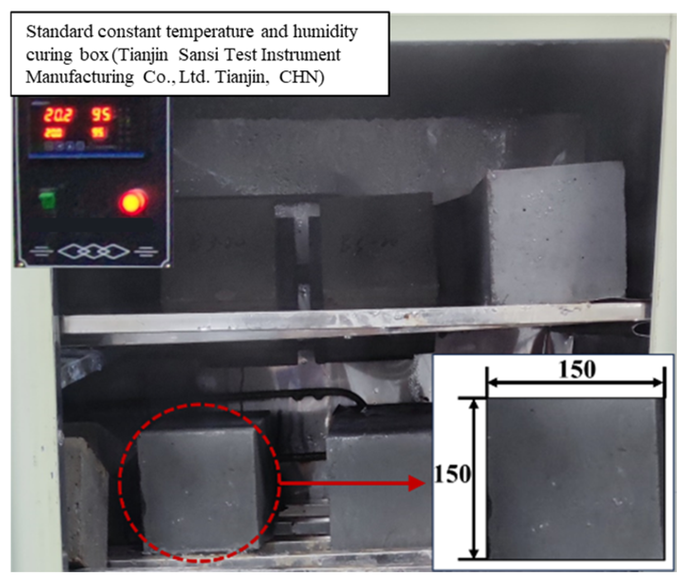
- GB/T 50081-2019; Standard for Test Methods of Concrete Physical and Mechanical Properties. Ministry of Housing and Urban–Rural Development of the People’s Republic of China: Beijing, China, 2019.
- Wang, J.T.; Kong, L.W.; Li, C.S.; Liu, B.H.; Yan, J.B. The Small Strain Stiffness Properties of Undisturbed Weathered Granite with Different Weathering Degrees. Front. Earth Sci. 2022, 10, 946437. [Google Scholar] [CrossRef]


| Model Construct | Material Type | Bulk Modulus/GPa | Shear Modulus/GPa | Density (kg/m3) | Saturation Density (kg/m3) | Internal Friction Angle (°) | Cohesion (MPa) | Tensile Strength (MPa) |
|---|---|---|---|---|---|---|---|---|
| Basis of bedrock layer | Granite | 23.81 | 21.74 | 2600 | 2860 | 51 | 12 | 10 |
| beams, piles, and surface layers | C40 concrete | 18.00 | 13.54 | 2500 | 2750 | 45 | 1.51 | 1.51 |
| Columns | C45 concrete | 18.61 | 13.96 | 2500 | 2750 | 45 | 1.6 | 1.6 |
| Categories | Vertical Displacement/mm | Maximum Tension Stress/MPa | Maximum Compressive Stress/MPa | |
|---|---|---|---|---|
| Mesh Types | Hexahedral mesh | 0.029 | 1.60 | 1.00 |
| Tetrahedral mesh | 0.022 | 1.62 | 1.04 | |
| Mesh Sizes | 1 m | 4.35 | 1.65 | 1.47 |
| 0.5 m | 4.04 | 1.65 | 1.44 | |
Disclaimer/Publisher’s Note: The statements, opinions and data contained in all publications are solely those of the individual author(s) and contributor(s) and not of MDPI and/or the editor(s). MDPI and/or the editor(s) disclaim responsibility for any injury to people or property resulting from any ideas, methods, instructions or products referred to in the content. |
© 2025 by the authors. Licensee MDPI, Basel, Switzerland. This article is an open access article distributed under the terms and conditions of the Creative Commons Attribution (CC BY) license (https://creativecommons.org/licenses/by/4.0/).
Share and Cite
Yang, C.; He, P.; Wang, S.; Wang, J.; Zhu, Z. Study on the Causes of Cracking in Concrete Components of a High-Pile Beam Plate Wharf. Buildings 2025, 15, 1352. https://doi.org/10.3390/buildings15081352
Yang C, He P, Wang S, Wang J, Zhu Z. Study on the Causes of Cracking in Concrete Components of a High-Pile Beam Plate Wharf. Buildings. 2025; 15(8):1352. https://doi.org/10.3390/buildings15081352
Chicago/Turabian StyleYang, Chao, Pengjuan He, Shaohua Wang, Jiao Wang, and Zuoxiang Zhu. 2025. "Study on the Causes of Cracking in Concrete Components of a High-Pile Beam Plate Wharf" Buildings 15, no. 8: 1352. https://doi.org/10.3390/buildings15081352
APA StyleYang, C., He, P., Wang, S., Wang, J., & Zhu, Z. (2025). Study on the Causes of Cracking in Concrete Components of a High-Pile Beam Plate Wharf. Buildings, 15(8), 1352. https://doi.org/10.3390/buildings15081352