Article

Comparative Study on the Foaming and Fireproof Properties of PDMS Foam Composites with Different Inorganic Fillers

College of Materials Science and Engineering, Nanjing Tech University, Nanjing 211816, China
*
Author to whom correspondence should be addressed.
Buildings 2025, 15(7), 1172; https://doi.org/10.3390/buildings15071172
Submission received: 12 March 2025 / Revised: 30 March 2025 / Accepted: 31 March 2025 / Published: 3 April 2025
(This article belongs to the Section Building Materials, and Repair & Renovation)

Abstract

In recent years, the increasing frequency of building fires has highlighted the limitations of traditional polymeric materials due to their inadequate fireproof performance. Ceramifiable polymer composites have emerged as a promising alternative by incorporating ceramic-forming fillers that create rigid ceramic-like structures through high-temperature eutectic reactions, offering exceptional thermal insulation and fireproof properties. These composites maintain structural integrity under fire exposure through sufficient mechanical strength retention. The effects of several ceramifiable inorganic fillers (CIFs) on the properties of polydimethylsiloxane (PDMS) foams were systematically investigated in this study. The research demonstrated that fillers with better matrix compatibility significantly enhance the foaming quality, mechanical performance, and fireproof capabilities. Notably, the CaCO3-filled PDMS foam composite (CPF-Ca) demonstrates exceptional foaming characteristics with 84% porosity and a remarkably low density of 0.36 g/cm3. The material achieves tensile and compressive strengths of 0.22 MPa and 0.84 MPa, representing 22% and 127% enhancements, respectively, compared to pure PDMS foam (PPF). Regarding the ceramic conversion capability, the sintered residue of CPF-Ca maintains a compressive strength of 4.39 MPa under high-temperature conditions. This composite material exhibited superior fireproof performance, successfully withstanding a butane torch for 300 s without penetration while maintaining a remarkably low backside temperature of merely 83.6 °C.

1. Introduction

With the continuous advancement of technology, polymer materials have found increasingly widespread applications in our daily lives [1,2,3]. However, most polymers are flammable and struggle to maintain their structural integrity during building fires [4,5,6]. They fail to prevent the further spread of flames and often lead to catastrophic consequences. Therefore, more effective measures are needed to enhance the flame retardancy and fire safety of polymer materials to prevent further building fire accidents.
The ceramification strategy has been employed to enhance the thermal insulation and fire resistance of various polymer matrices, including polyolefins, silicone rubbers, polyurethanes, EVA, and epoxy resins [7,8,9,10,11]. These ceramifiable polymer composites (CPMs) are typically produced by incorporating CIFs and sintering aids during polymer processing. When exposed to high temperatures, the fillers and aids react to form a rigid ceramic-like skeleton through eutectic reactions [12]. This skeleton effectively protects the underlying structure from fire damage. As a result, CPMs, with their exceptional high-temperature performance, are widely used in applications, such as building materials [13,14], wire and cable insulation [15,16], and aerospace components [17,18].
Compared to traditional polymers, silicone rubber exhibits superior temperature tolerance and inherent flame retardancy due to the higher bond energy of its Si-O-Si backbone [19,20,21]. However, pure silicone rubber remains susceptible to direct flame impacts, necessitating more effective strategies to enhance its fireproof performance [22,23]. Additionally, the primary pyrolysis product of silicone rubber at high temperatures is SiO2, which facilitates the bonding of inorganic fillers, thereby forming a stronger ceramic matrix [24]. Notably, PDMS demonstrates excellent compatibility with inorganic fillers and generates a significant amount of amorphous silica at elevated temperatures [25]. Consequently, ceramifiable silicone rubber composites hold great potential for applications in cable insulation sheaths, thermal insulation, and sealing materials, as well as fireproof coatings for various building applications.
Previous studies have investigated various inorganic fillers with distinct functional advantages. Anyszka et al. demonstrated that kaolin enhances mechanical properties, while calcium-based fillers maximize flame retardancy and ceramic-like residue strength, through their investigation of TiO2, CaCO3, Al(OH)3, and kaolin effects on vulcanized silicone rubber [26]. Similarly, Wang et al. systematically compared the impacts of kaolin, sericite, bentonite, and alumina on both the mechanical properties and high-temperature ablation resistance of silicone rubber [25]. In PDMS foam applications, Xu et al. achieved superior crack resistance using mica and low-melting glass powder [27], whereas Chen et al. enhanced flame retardancy and fire resistance through clay/glass powder composites combined with GO/aqueous foaming agents [18]. Compared with their thermally cured counterparts, room-temperature foamed PDMS composites generally exhibit preferred characteristics, including superior thermal insulation and reduced density. However, a crucial yet underexplored factor in previous research lies in how different CIFs influence PDMS foaming behavior. These fillers significantly alter the foaming performance during manufacturing, subsequently affecting the structural uniformity of the final foam matrix, which is a determinant factor governing mechanical properties, thermal insulation, and fireproof performance. Therefore, the strategic selection of ceramifiable fillers to engineer lightweight PDMS foam materials with enhanced thermal insulation and superior structural integrity under flame exposure will provide critical guidance for advancing the development of high-performance building insulation systems.
In the preparation of ceramifiable polymer materials, the selection of ceramifiable fillers typically includes silicon-based, calcium-based, and aluminum-based types. Silicon-based mineral materials (e.g., mica, kaolin, wollastonite (Wo), montmorillonite(MMT)) have been reported to achieve excellent ceramification performance in various ceramifiable polymer systems [12]. However, in this work, preliminary studies revealed that kaolin and MMT excessively affected the foaming performance of PDMS foam; thus, they were excluded, and mica and wollastonite were selected instead. Similarly, calcium carbonate (CaCO3) and alumina Al2O3 were chosen as calcium-based and aluminum-based ceramifiable fillers, respectively, following preliminary investigations.
In this work, ceramifiable PDMS foam composites were fabricated using mica, CaCO3, Wo, and Al2O3 as the CIF and SGF as a sintering aid. All fillers were employed in their raw state without surface modification, ensuring cost-effectiveness in production. The effects of these fillers on the foaming behavior, mechanical properties, thermal stability, ceramification, and fireproof performance were characterized. Ceramifiable PDMS foam composites with enhanced porosity and superior thermal insulation performance were successfully developed. The optimized material architecture demonstrates significant improvements in the structural homogeneity and functional characteristics, highlighting the critical role of tailored filler selection in advancing fire-resistant polymer foam technologies.

2. Materials and Methods

2.1. Materials

Mica powder and wollastonite were sourced from Anhui Grea New Material Technology Co., Ltd. (Chuzhou, China) Nano-sized calcium carbonate was obtained from Hunan Jinjian New Material Technology Co., Ltd. (Yongzhou, China), while alumina (AR grade) was purchased from Shanghai Macklin Biochemical Technology Co., Ltd. (Shanghai, China). SGF (melting point ~400 °C) was supplied by Shanggao Mingzheng Plastics Co., Ltd. (Shaoxing, China). Silicone oils, such as hydroxyl-terminated polydimethylsiloxane (Hy-PDMS), vinyl-terminated polydimethylsiloxane (Vi-PDMS), and hydrogen-containing polydimethylsiloxane (H-PDMS), were obtained from Shandong Dayi Chemical Co., Ltd. (Yantai, China), and the platinum catalyst (5000 ppm concentration) was acquired from Guangzhou Xiyou New Materials Co., Ltd. (Guangzhou, China). All materials were used as received without further purification or treatment.

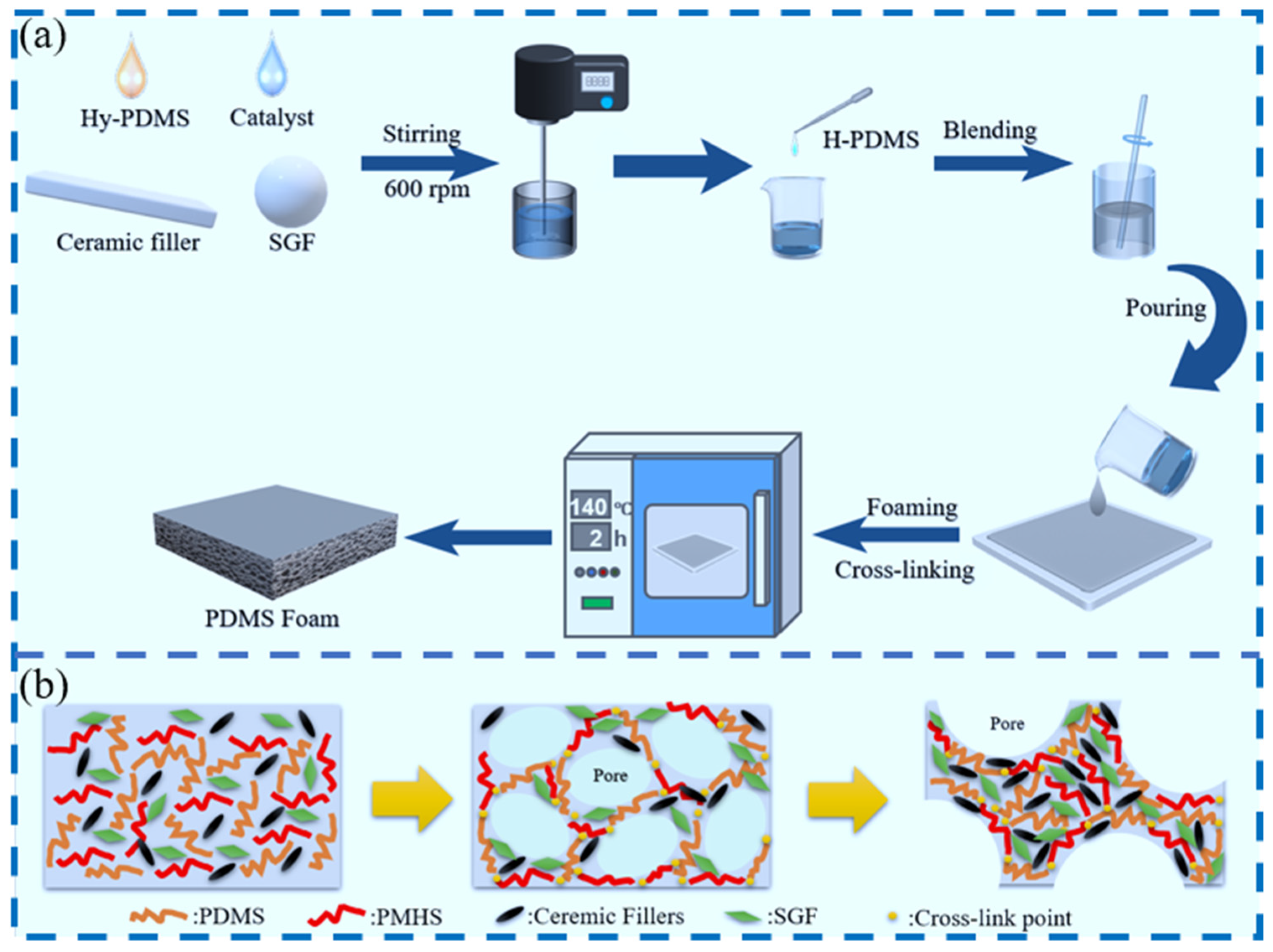
2.2. Preparation of PDMS Foam

The preparation process and formation mechanism of the PDMS foam composite are illustrated in Figure 1. Initially, all components except H-PDMS were precisely measured according to the proportions specified in Table 1 and thoroughly mixed using a high-speed mixer to obtain a homogeneous prepolymer solution. Subsequently, H-PDMS was incorporated into the prepared mixture and manually stirred to ensure uniform distribution. The blended solution underwent spontaneous foaming at ambient temperature. Following primary solidification, the composites were subjected to secondary curing in a vacuum oven maintained at 140 °C to complete curing.

2.3. Characterization

2.3.1. Apparent Density Test

The apparent density of specimens was determined in accordance with ASTM D3574 specifications [28]. Sample dimensions (length, width, and height) were measured using digital vernier calipers to calculate the volume, while mass quantification was performed using a precision analytical balance. The apparent density (ρ) was calculated via Equation (1):
ρ = m v
where ρ represents the apparent density (g/cm3), m denotes the sample mass (g), and v   indicates the sample volume (cm3).

2.3.2. Cell Diameter Test

Foam cell diameter quantification was conducted using ImageJ 1.46 software with a crosshair measurement protocol. Forty randomly selected cells in foam cross-sectional micrographs were measured to establish diameter distribution profiles, followed by Gaussian distribution curve fitting for statistical analysis.

2.3.3. Porosity Test

Sample porosity ( ) was calculated using Equation (2):
= ( 1 ρ f ρ s ) × 100
where represents the porosity (%), ρ f denotes the apparent density of the PDMS foam (g/cm3), and ρ s indicates the density of solid silicone elastomer (g/cm3).

2.3.4. Open-Cell Content Test

Open-cell content determination employed a vacuum immersion method with distilled water as the medium. Specimens were submerged 50 mm below the water surface under a 0.01 MPa vacuum for 3 min, followed by atmospheric pressure immersion for an equivalent duration. After surface moisture removal with filter paper, samples were immediately weighed to 0.001 g precision. The open-cell ratio ( K ) was derived via Equation (3):
K = W × ρ f × 100 %
where K signifies the open-cell content (%), W corresponds to vacuum water absorption (%), ρ f is the apparent density (g/cm3), and represents the porosity (%).

2.3.5. Rotational Viscosity Test

Rotational viscosity measurements of the rubber compound were conducted using an NDJ-2 rotational viscometer (Shanghai Licheng Precision Instrument Co., Shanghai, China) following GB/T 2794-2013 guidelines [29], with standardized testing parameters employing rotor #4 at 30 rpm.

2.3.6. Mechanical Test

The mechanical properties of the samples were tested using a CMT5254 universal testing machine (Shenzhen Xinsansi Measurement Technology Co., Shenzhen, China). In accordance with the ASTM D1056 standard [30], the compression performance of the samples was tested. The samples were cylindrical, cut using a die cutter, with a diameter of 29.0 mm ± 0.5 mm and a height of 12.5 mm ± 0.5 mm. The samples were compressed at a speed of 10 mm/min until a strain of 50% was achieved. Following the ASTM D3574 standard, the tensile performance of the samples was tested. The samples were dumbbell-shaped and cut using a die cutter.

2.3.7. X-Ray Diffraction (XRD)

Post-ablation ceramic-like residues were analyzed for crystalline phases using X-ray diffraction (Rigaku SmartLab SE, Tokyo, Japan) with a scanning rate of 10°/min across the 5–90° 2θ range.

2.3.8. X-Ray Fluorescence (XRF)

The chemical composition profiling of mica, Wo, and SGF was performed via ADVANT XP X-ray fluorescence (XRF; RIGAKU ZSX Primus, Tokyo, Japan) spectroscopy, with quantitative results detailed in Table 2.

2.3.9. Thermogravimetric Analysis (TGA)

The thermogravimetric analysis (Beijing Zealres Technology Co., Ltd. HQT-4, Beijing, China) was conducted on 5–10 mg foam samples under a nitrogen atmosphere using a heating rate of 10 °C/min from ambient temperature to 800 °C to record the mass loss profiles.

2.3.10. Scanning Electron Microscope (SEM)

The microstructures of PDMS foam composites before and after ceramization were observed using a scanning electron microscope (JEOL Ltd. JSM-6510, Tokyo, Japan) operating at a 10 kV acceleration voltage.

2.3.11. Ceramification Test

Using a KSL-1400X muffle furnace X (Hefei Kejing Material Technology Co., Hefei, China), samples with side lengths of 20 ± 5 mm were heated from room temperature to 600 °C, 800 °C, and 1000 °C, respectively, at a heating rate of 10 °C/min. All samples were held at the maximum temperature for 30 min and then allowed to cool naturally to room temperature.

2.3.12. Fireproof Performance Test

In the fireproof performance test, a butane torch with a flame temperature of approximately 1000 °C was used as the flame source. All the PDMS foam composites measuring 100 mm × 100 mm × 10 mm were combined with a 0.5 mm-thick aluminum plate and fixed onto an iron bracket. The butane torch was applied for 300 s of ablation, with the sample surface positioned 10 cm away from the torch. The temperature on the back side of the aluminum plate was recorded using a K-type thermocouple.

3. Results and Discussion

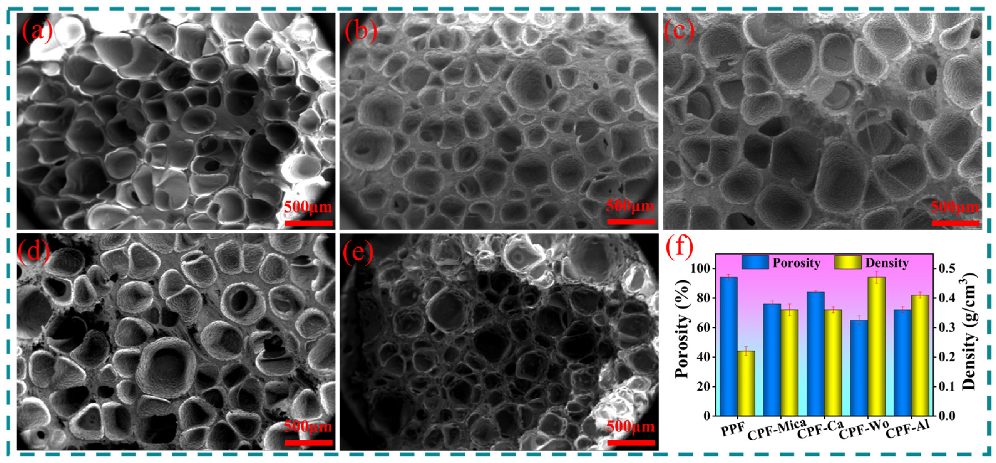
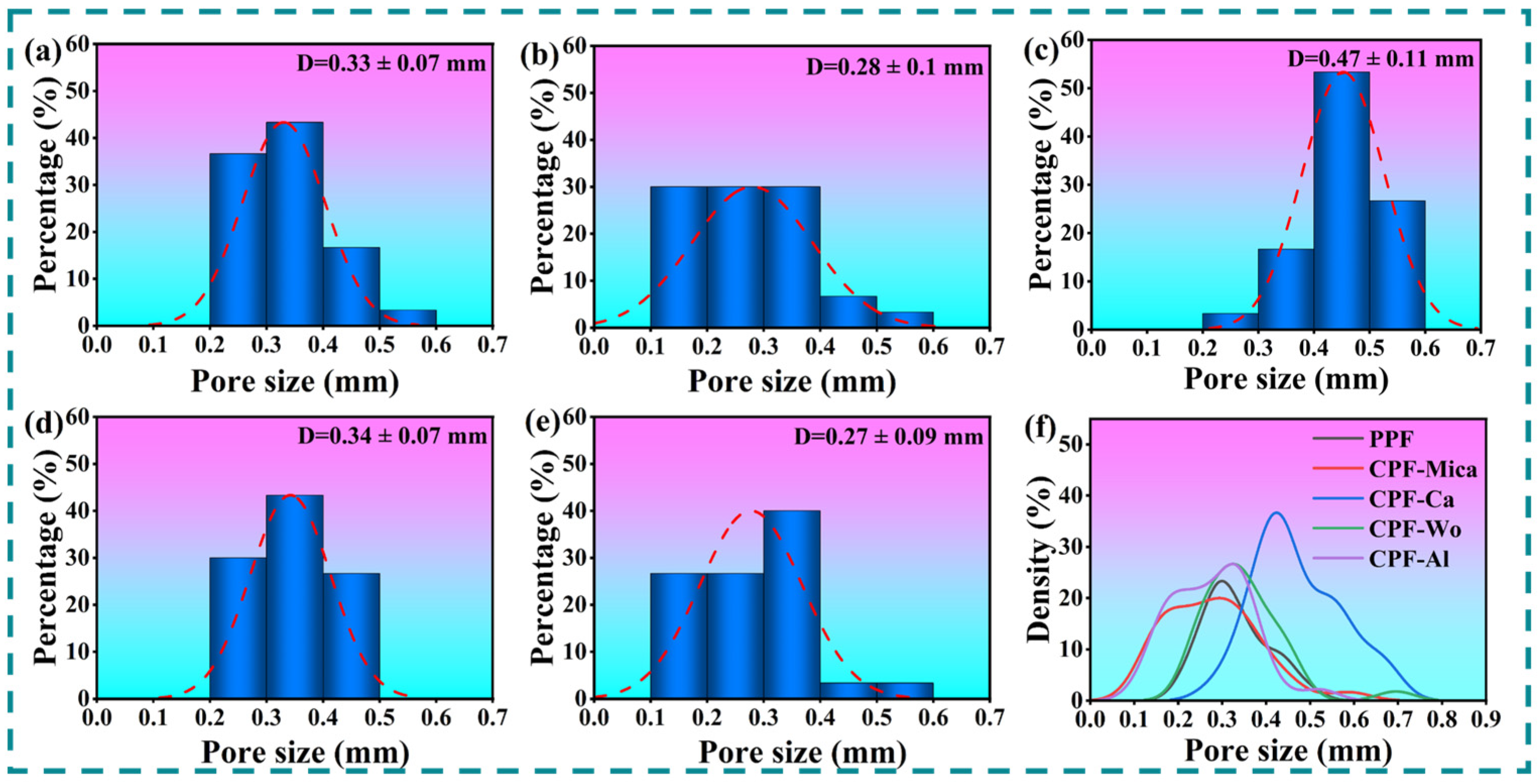
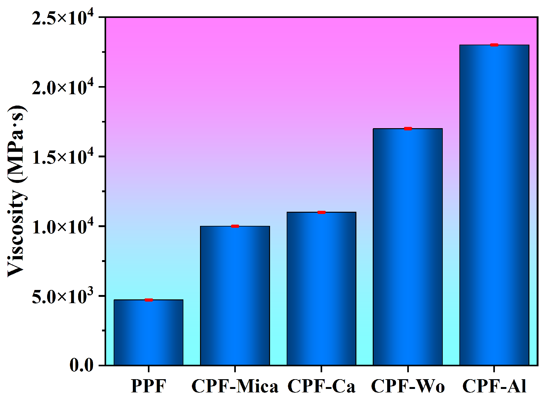
3.1. Analysis of Foaming Properties

Figure 2 presents cross-sectional SEM micrographs comparing the cellular architectures of different PDMS foam composites. The PPF exhibited superior porosity with thin cell walls, corresponding to its minimal density of 0.22 g/cm3. As shown in Figure 2f, CIF incorporation systematically increased the composite densities through two mechanisms: (1) intrinsic high density of inorganic additives and (2) structural modifications, including thickened cell walls and reduced porosity. CPF-Wo demonstrated the most pronounced densification (0.47 g/cm3) with the lowest porosity (65%), attributable to the hydrophilic nature of wollastonite that compromised dispersion homogeneity in hydrophobic PDMS. This interfacial incompatibility promoted filler aggregation, creating dense regions that restricted bubble formation. In contrast, CPF-Mica and CPF-Ca maintained lower densities (~0.36 g/cm3), with CPF-Ca achieving optimal porosity (84%) through superior dispersibility and surface modification compatibility of nano-CaCO3.
To better understand the foaming properties of various PDMS foam composites, cell size distribution analysis was performed on the micrographs in Figure 2, as shown in Figure 3. The PPF exhibited the largest mean pore diameter of 0.33 mm. The incorporation of inorganic fillers systematically reduced cellular dimensions, with CPF-Al achieving the smallest average pore size (0.27 mm). The observed structural transformation principally arose from controlled viscosity adjustment in the PDMS precursor system (Figure 4), where the introduction of inorganic fillers induced substantial elevation of the composite viscosity, consequently constraining bubble growth dynamics during the foaming process [31]. Distinct CIFs induced varying degrees of viscosity enhancement, ultimately dictating their respective pore size reduction efficiencies. On the contrary, for CPF-Ca, the increased bubble nucleation sites on the surface of active nano-sized calcium carbonate fillers promoted coalescence between adjacent bubbles during the foaming process. This phenomenon resulted in an expansion of average pore diameter to 0.47 mm, while simultaneously enhancing pore uniformity compared to conventional formulations.

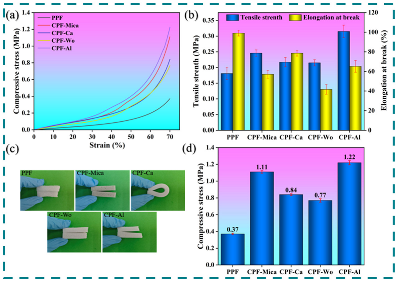
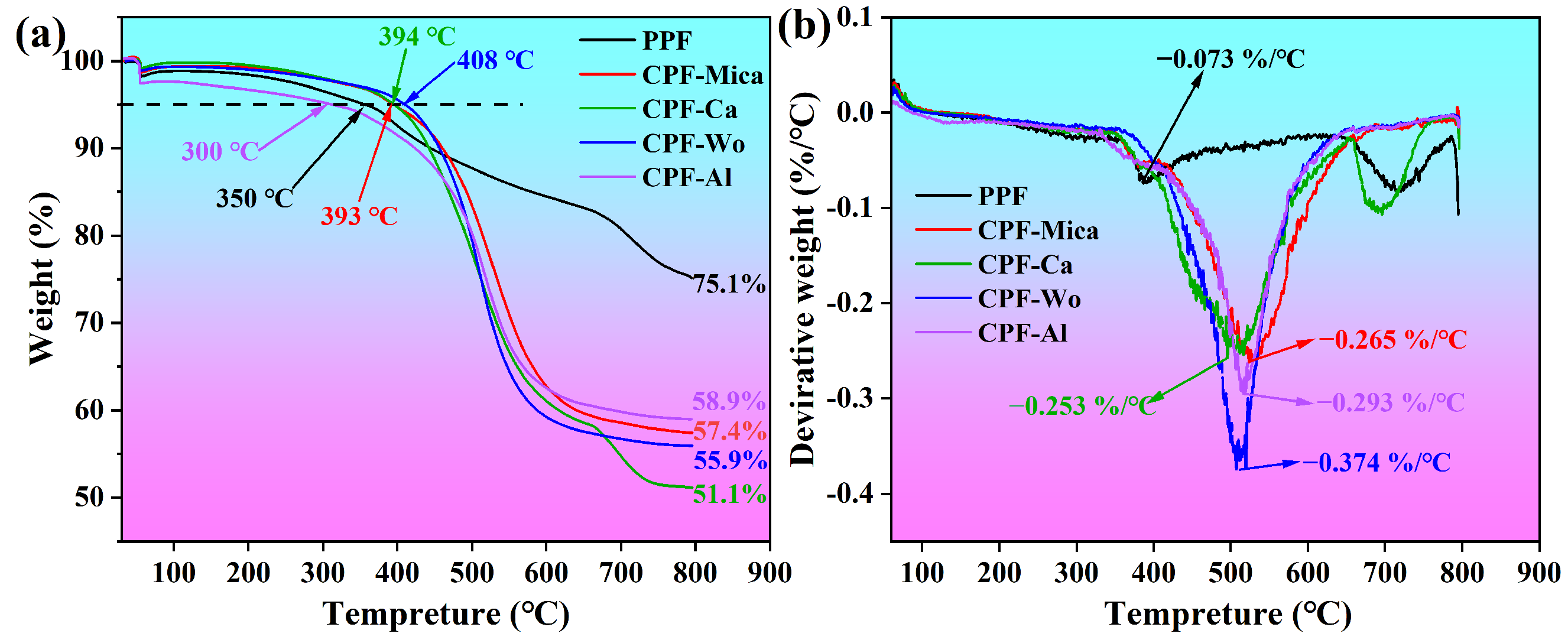
3.2. Analysis of Mechanical and Thermal Performance

Figure 5 presents the mechanical performance characteristics of various PDMS foam composites. As shown in Figure 5a, all ceramifiable composites retained the typical compression strain–stress profile of hyperelastic materials despite filler incorporation [32]. Figure 5b,d demonstrate that CIFs generally enhanced the mechanical strength parameters: the tensile strength showed maximum improvement in CPF-Al (0.32 MPa), representing a 78% increase over PPF, while compressive strength improvements ranged from 108 to 230% across different systems. These enhancements can be attributed to the formation of additional hydrogen bonds between the incorporated fillers and the polymer matrix, which strengthened the resistance of the material to external forces. However, this reinforcement came at the expense of the elongation capacity. CPF-Wo exhibited the most severe ductility reduction with merely a 40% elongation at break, attributed to the poor interfacial compatibility between hydrophilic wollastonite particles and the hydrophobic PDMS matrix. This incompatibility induced filler agglomeration and localized stress concentrations that initiated premature fracture. Notably, CPF-Ca demonstrated unique flexibility retention in 180° bending tests without structural failure, suggesting effective stress dissipation through optimized filler–matrix interactions.
Figure 6 compared the TG and DTG profiles of PDMS foam composites. Notably, the CPF-Mica, CPF-Ca, and CPF-Wo demonstrated improved initial thermal stability with 5% mass loss temperatures elevated by 43 °C, 44 °C, and 58 °C, respectively, compared to PPF. However, this early-stage advantage was reversed at elevated temperatures, as evidenced by significantly reduced final residue yields at 800 °C. This contradictory phenomenon demonstrated the dual catalytic functionality of CIFs. While physically impeding initial decomposition through barrier effects, the Na/K ions originating from SGF ultimately enhanced PDMS degradation via ionic catalysis [25]. Metallic cations preferentially interacted with siloxane bonds, effectively lowering the activation energy for chain scission and facilitating the generation of volatile cyclic oligomers, consequently reducing the ultimate mass residue ratio.

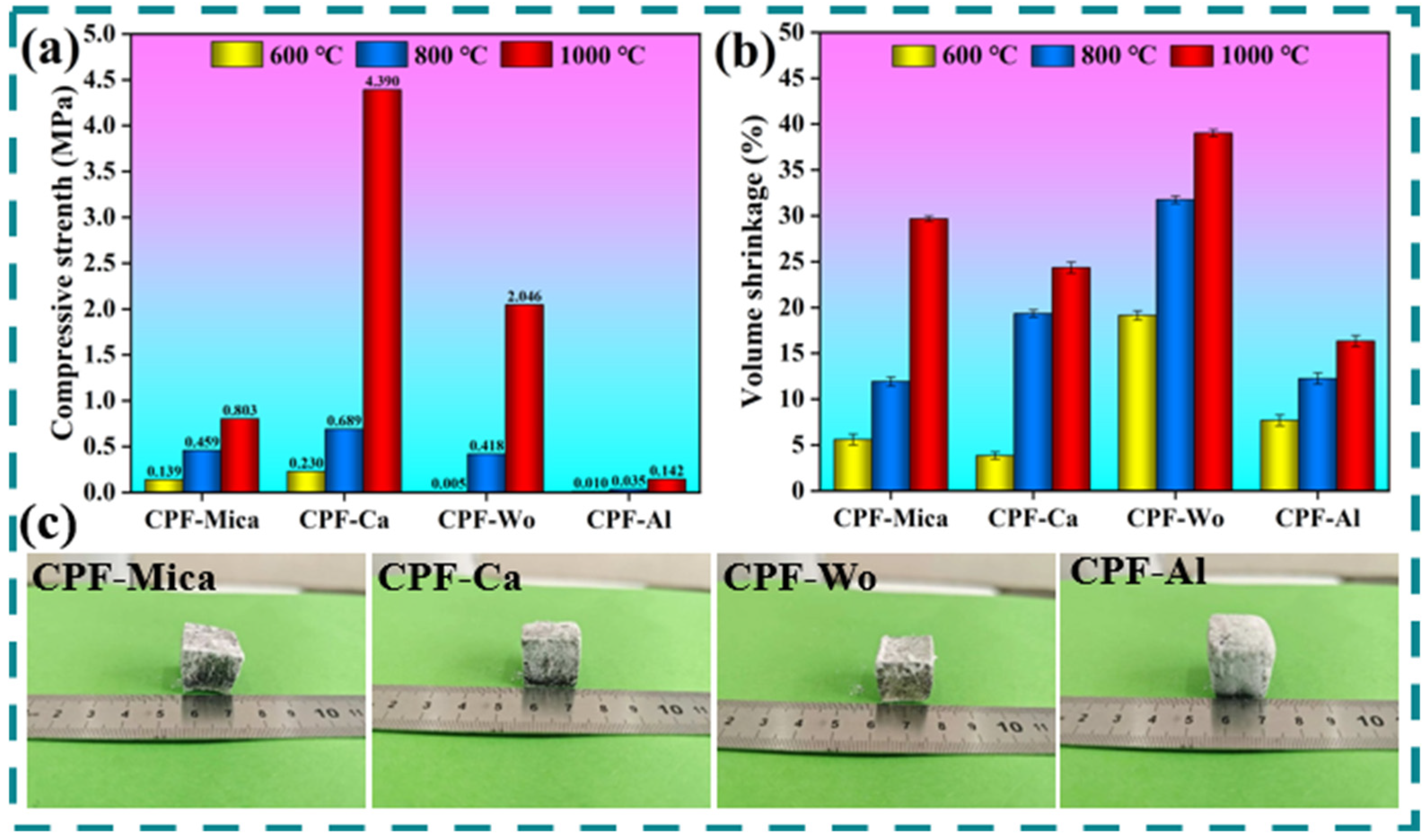
3.3. Analysis of Ceramification Performance

The ceramification performance of PDMS foam composites with different CIFs was evaluated through controlled muffle furnace heating followed by XRD analysis of the residues. As shown in Figure 7a, CPF-Ca specimens heated to 600 °C exhibited significant crystalline phase evolution in XRD patterns, with characteristic diffraction peaks at 11.5°, 23.1°, 25.3°, 26.8°, and 29.9° corresponding to monoclinic pseudo-wollastonite (PDF#27-0088), while peaks at 20.8°, 26.6°, 64°, and 68.3° matched hexagonal quartz (PDF#27-0114). The quartz phase formation originated from PDMS backbone degradation, whereas pseudo-wollastonite emergence resulted from interfacial reactions between CaO (derived from CaCO3 decomposition) and silica components. With temperature elevation to 800 °C, a new diffraction peak emerged at 21.9° corresponding to tetragonal cristobalite (PDF#39-1425), indicating progressive quartz-to-cristobalite phase transformation. Complete phase conversion was confirmed at 1000 °C through the disappearance of the characteristic quartz peak at 20.8°. Notably, differential phase distribution was observed between surface and core regions in 1000-sintered samples. The outer surface of the foam, which was directly exposed to high temperatures, rapidly decomposes to form a dense silicate phase shell. Due to the low thermal conductivity of the foam, the internal matrix undergoes delayed heating, and the melted fluxing agents fail to rapidly form ceramic phases, thus separating from the outer shell layer. The CO2 generated in CPF-Ca due to the decomposition of CaCO3 further promotes this process. Consequently, the material forms two distinct regions, an outer shell and an inner core, after sintering. The core section showed reduced cristobalite peak intensity at 20.8° coupled with an enhanced pseudo-wollastonite signal at 29.9°, compared to the outer shell layer.
Figure 7b reveals the distinct ceramization behaviors among other PDMS foam composites under 800 °C sintering. The PPF specimen exhibited an amorphous “hump” in its XRD pattern, indicating the absence of crystalline phase formation. For CPF-Mica, the characteristic muscovite diffraction peaks at 8.8° and 17.8° disappeared completely, leaving residual peaks at 20.8°, 26.6°, and 50.1° corresponding to the quartz phase (PDF#27-0114), demonstrating the inability of the system to generate crystalline silicate phases under high-temperature treatment. CPF-Wo displayed no new diffraction peaks but showed significant intensity variations, with reduced quartz peak intensity at 26.6° and an enhanced pseudo-wollastonite signal at 29.9° (PDF#27-0088). This intensity redistribution confirmed the progressive formation of new silicate crystalline phases through interfacial reactions between decomposed PDMS products and inorganic fillers. In contrast, CPF-Al developed a new diffraction peak at 21.8° matching α-tridymite (PDF#42-1401), suggesting the coexistence of alumina and α-tridymite phases. This dual-phase structure originated from incomplete ceramization due to the high thermal stability and limited reactivity of alumina with silica components.
Figure 8a presents the compressive strength of sintered residues derived from PDMS foam composites containing different CIFs after calcination at various temperatures. The PPF disintegrated completely during calcination and therefore was excluded from the comparison. The data revealed a temperature-dependent strengthening behavior across all samples. Notably, the CPF-Ca demonstrated the most significant enhancement, achieving 4.39 MPa compressive strength at 1000 °C, surpassing the 2.5 MPa value reported by Xu et al. [27], indicating superior structural stability under flame exposure. This superior performance originated from the synergistic combination of silicate crystalline phases (formed through CaCO3-SiO2 interactions) and SGF, which collectively constructed a robust ceramic-like skeletal structure. In contrast, CPF-Mica and CPF-Al exhibited comparatively lower mechanical strength, consistent with their limited crystalline phase development observed in the XRD analysis.
The volumetric shrinkage characteristics shown in Figure 8b provided further insights into the structural evolution. At 600 °C, CPF-Ca displayed minimal shrinkage (4.3%), attributable to the counterbalancing effects between CO2-induced expansion from CaCO3 decomposition and PDMS degradation-induced contraction. However, elevated temperatures (800–1000 °C) induced substantial shrinkage across all PDMS foam composites, particularly in CPF-Wo, which exhibited 39% volumetric contraction at 1000 °C. This dramatic dimensional change correlated with intensified phase transformations and structural densification processes at higher temperatures.
These results collectively demonstrated that filler selection critically governed both the mechanical reinforcement efficiency and dimensional stability during ceramic conversion, with CaCO3 showing the optimal balance between strength development and shrinkage control.

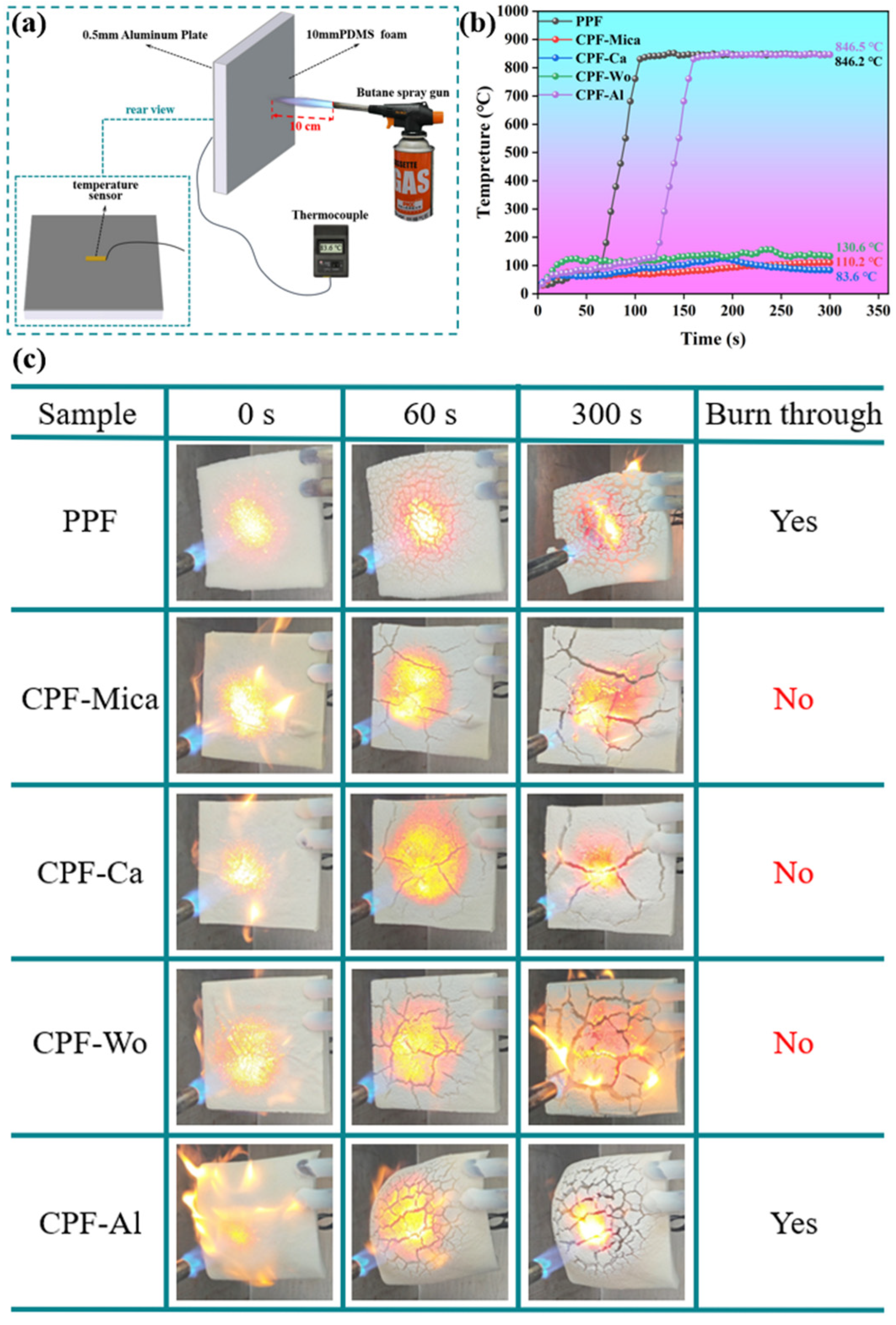
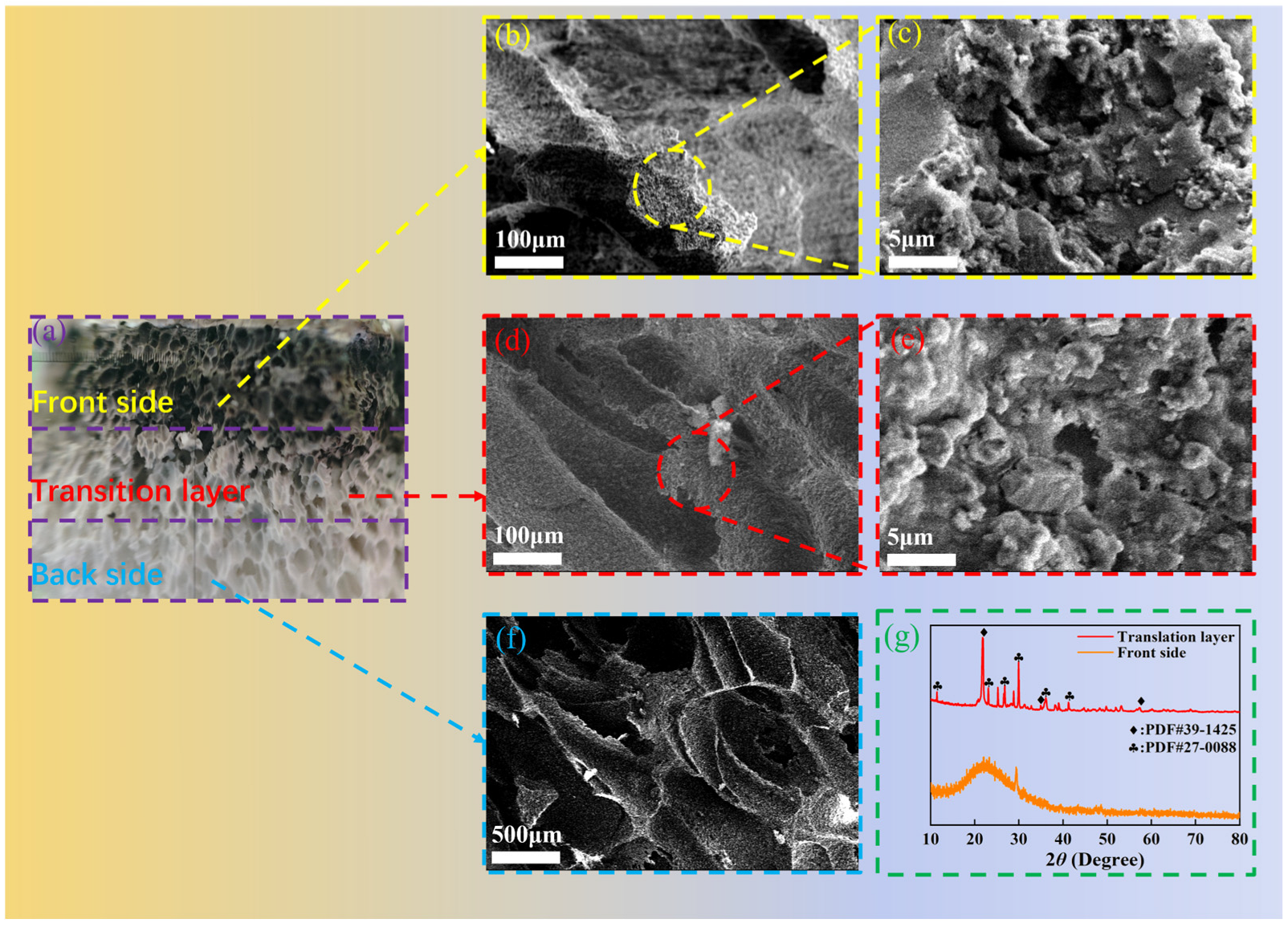
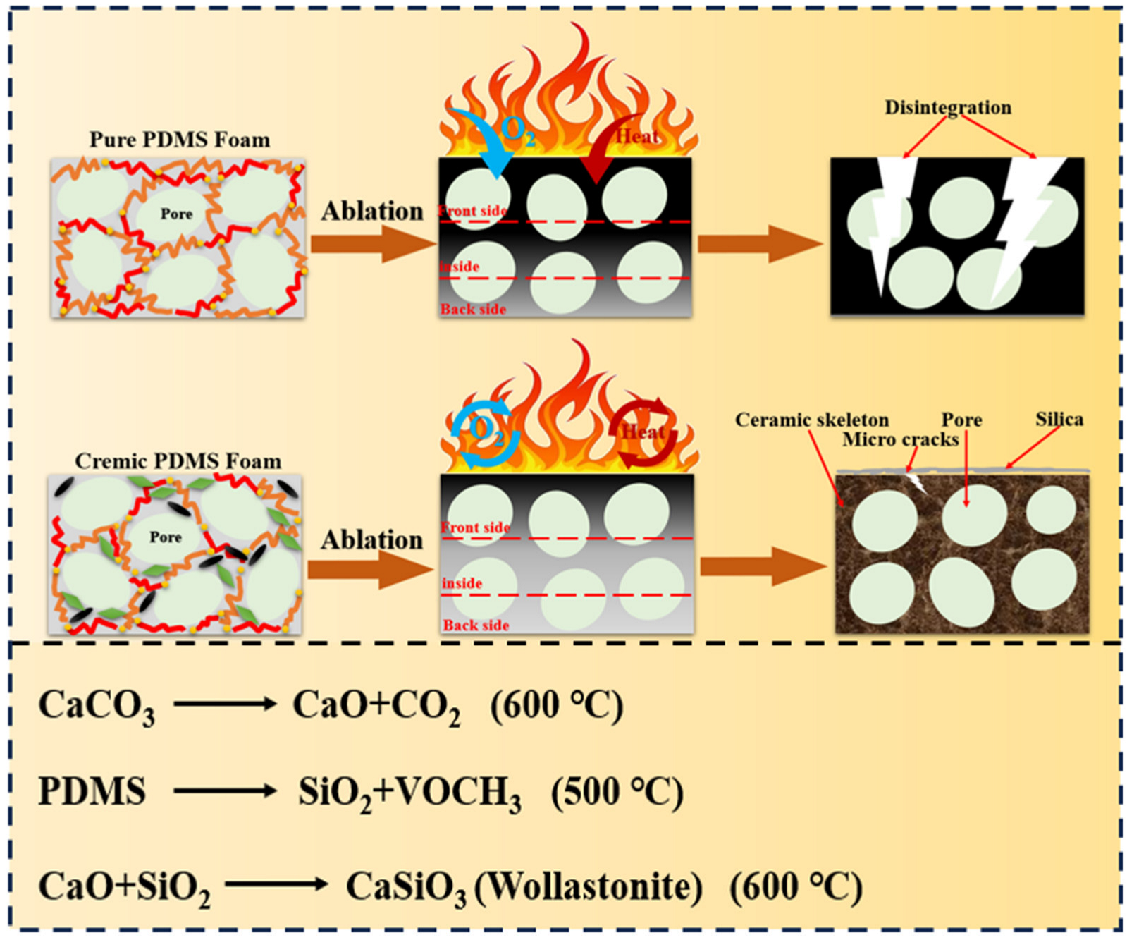
3.4. Analysis of Fireproof Performance and Mechanism

The fireproof performance of various PDMS foam composites was evaluated through a 1000 °C butane torch test, with the experimental configuration illustrated in Figure 9a. Figure 9c displays the surface morphological evolution of different PDMS foams under flame ablation. As shown in the figure, the PPF exhibited immediate surface fissuring upon flame exposure, accompanied by rapid decomposition and the scission of internal molecular chains, resulting in catastrophic structural collapse. The foam suffered complete penetration within merely 60 s of ablation, and its backside temperature escalated to 846.3 °C after sustained 300 s thermal exposure. In contrast, CPF-Mica, CPF-Ca, and CPF-Wo composites demonstrated superior performance through a synergistic interaction between CIFs and SGF, which rapidly formed effective thermal barrier layers at elevated temperatures. These ceramic-like structures effectively hindered heat penetration and protected the underlying PDMS chains from further degradation. While minor surface cracks were observed during ablation, all three composites maintained structural integrity throughout the 300 s test. The post-ablation backside temperatures measured 110.2 °C for CPF-Mica, 130.6 °C for CPF-Wo, and a notably lower 83.6 °C for CPF-Ca, which also displayed minimal surface cracking among all tested samples. Conversely, CPF-Al failed to form protective ceramic-like barriers due to the excessively high ceramization temperature of alumina, resulting in structural penetration after 120 s and an elevated backside temperature of 846.5 °C following a 300 s ablation.
Following a comprehensive analysis, the 10 mm-thick CPF-Ca demonstrated superior thermal insulation and fireproof performance by maintaining a backside temperature of only 83.6 °C after 300 s butane flame ablation. This performance significantly surpasses both the 140 °C backside temperature recorded for the 10 mm-thick ceramifiable PDMS foam developed by Xu et al. [27] under identical testing conditions and the 257 °C backside temperature observed in the 20 mm-thick ceramifiable PDMS foam created by Chen et al. [18] during comparable ablation experiments.
To investigate the fireproof mechanism of CPF-Ca, SEM morphological characterization and XRD phase analysis were conducted on the ablation residues of foam samples subjected to butane flame treatment. As illustrated in Figure 10a, the post-ablated CPF-Ca residue exhibited a transitional structure configuration. The flame-exposed surface was covered with a white powdery substance, identified through XRD analysis (Figure 10g) as quartz-phase SiO2 derived from high-temperature degradation of the PDMS, evidenced by characteristic quartz-phase diffraction peaks. The intermediate layer maintained the original porous architecture of the foam through ceramic-like structure formation, with an XRD phase composition consistent with that of muffle furnace-ablated CPF-Ca samples. Furthermore, a microscopic examination revealed that the unexposed back layer retained its pristine foam morphology without thermal decomposition, demonstrating effective thermal protection of the underlying structure.
The fireproof mechanism of CPF-Ca, as depicted in Figure 11, operated through a sequential structural evolution during thermal ablation. Firstly, surface shielding occurred when the PDMS matrix in the surface layer underwent rapid pyrolysis under flame exposure, generating amorphous SiO2 particulates that formed an initial thermal barrier to block oxygen infiltration and heat transfer. Subsequently, intermediate ceramization took place as CaO, derived from the decomposition of CaCO3, reacted with SiO2 from PDMS degradation. This reaction, facilitated by liquid-phase bridging effects mediated by molten SGF, crystallized into wollastonite (CaSiO3), establishing a continuous oxygen-blocking ceramic-like network while maintaining the porous architecture of the foam. Finally, structural insulation was achieved through the hierarchical porosity of the ceramicized framework (inherited from the precursor foam), which created convoluted heat-transfer pathways. This effect synergized with the inherently low thermal conductivity of CaSiO3 to deliver exceptional thermal insulation performance. In contrast, PPF suffered rapid structural deterioration due to uncontrolled degradation mechanisms, such as thermal stress, surface ablation, oxygen penetration, and matrix decomposition. CPF-Ca overcame these limitations through self-regulating phase transformations, including protective layer formation, kinetically controlled gradient ceramization, and thermal decoupling between structural components. These coordinated mechanisms maintained the foam matrix integrity during prolonged fire exposure, ultimately stabilizing a hierarchical porous ceramic-like framework that significantly improved the fireproof performance of PDMS composites.

4. Conclusions

This work demonstrated that the foaming characteristics of PDMS foams were significantly influenced by CIF types, directly affecting the cellular uniformity, porosity, and density. Notably, CPF-Al exhibited the most pronounced reduction in pore homogeneity, likely attributable to the alkaline nature of alumina particles. Subsequent mechanical evaluations confirmed that superior cellular uniformity correlated with enhanced performance, with only CPF-Ca maintaining exceptional properties. The improved self-supporting capability was obtained in filled samples (except alumina), particularly in CPF-Ca, which developed the strongest ceramic-like architecture.
The CPF-Ca foam exhibited exceptional thermal resistance, sustaining a remarkably low backside temperature exposure to butane flame. By contrast, PPF and CPF-Al specimens failed during testing, leading to rapid temperature escalation. These types of PDMS foams delivering exceptional thermal insulation and fireproof capabilities would have great applications in building materials.

Author Contributions

X.H.: Conceptualization, Methodology, Validation, Formal analysis, Investigation, Data curation, Writing original draft, Visualization. M.Y.: Conceptualization, Methodology, Validation, Formal analysis. F.H.: Conceptualization, Methodology, Formal analysis, Writing-review and editing. G.J.: Supervision. Y.S.: Conceptualization, Methodology, Formal analysis, Writing- review and editing, Supervision, Funding acquisition. All authors have read and agreed to the published version of the manuscript.

Funding

This work was financially supported by the National Natural Science Foundation of China (No. 22175088), Priority Academic Program Development of Jiangsu Higher Education Institutions (PAPD).

Data Availability Statement

The original contributions presented in this study are included in the article. Further inquiries can be directed to the corresponding author.

Conflicts of Interest

The authors declare no conflicts of interest.

References

  1. Cai, S.; Deng, X.; Beiyuan, J.; Chen, X.; Liu, D.; Lv, D.; Duan, C.; Lin, L.; Cha, R.; Xie, W. Review of synthetic polymer-based thermal insulation materials in construction and building. J. Build. Eng. 2024, 97, 110846. [Google Scholar]
  2. Chen, J.; Liu, X.; Tian, Y.; Zhu, W.; Yan, C.; Shi, Y.; Kong, L.B.; Qi, H.J.; Zhou, K. 3D-Printed anisotropic polymer materials for functional applications. Adv. Mater. 2022, 34, 2102877. [Google Scholar]
  3. Yuen, A.C.Y.; Chen, T.B.Y.; Cordero, I.M.D.C.; Liu, H.; Li, A.; Yang, W.; Cheung, S.C.P.; Chan, Q.N.; Kook, S.; Yeoh, G.H. Developing a solid decomposition kinetics extraction framework for detailed chemistry pyrolysis and combustion modelling of building polymer composites. J. Anal. Appl. Pyrolysis 2022, 163, 105500. [Google Scholar]
  4. Ao, X.; Vázquez-López, A.; Mocerino, D.; González, C.; Wang, D.-Y. Flame retardancy and fire mechanical properties for natural fiber/polymer composite: A review. Compos. Part B Eng. 2024, 268, 111069. [Google Scholar] [CrossRef]
  5. Wu, Z.; Zhao, Y.; Li, H.; Zeng, X.; Lin, J.; Wu, J.; Zhou, Y.; Chen, G.; Lai, X. Multifunctional ceramifiable silicone foam for smart fire fighting. Chem. Eng. J. 2024, 496, 154149. [Google Scholar] [CrossRef]
  6. Wilkie, C.A.; Morgan, A.B. Fire Retardancy of Polymeric Materials; CRC Press: Boca Raton, FL, USA, 2024. [Google Scholar]
  7. Deng, Z.; Shi, M.; Huang, Z.; Yu, X.; Wu, Y.; Yang, X. Oxidation resistance, ablation resistance and in situ ceramization mechanism of Al-coated carbon fiber/boron phenolic resin ceramizable composites modified with Ti3SiC2. Ceram. Int. 2023, 49, 32490–32502. [Google Scholar]
  8. Yang, C.; Gong, M.; Yang, F.; Liang, J.; Jin, P. Molecular Dynamics Simulation of Ceramic Polyolefin for Fire Resistant Cable. In IOP Conference Series: Earth and Environmental Science; IOP Publishing: Bristol, UK, 2021; p. 012025. [Google Scholar]
  9. Wang, Y.; Lai, X.; Li, H.; Liu, T.; Zeng, X. Significantly improve fire safety of silicone rubber by efficiently catalyzing ceramization on fluorophlogopite. Compos. Commun. 2021, 25, 100683. [Google Scholar] [CrossRef]
  10. Liu, T.; Yao, Y.; Zhao, D.; Hu, F.; Yun, C.; Jiang, G.; Shen, Y.; Wang, T. Improving thermal insulation and fire resistance of ceramifiable EVA/ceramic hybrid composites via low temperature sintering and foaming strategy. Ceram. Int. 2024, 50, 6207–6219. [Google Scholar]
  11. Liu, L.; Xiang, D.; Wu, L. Improved thermal conductivity of ceramic-epoxy composites by constructing vertically aligned nanoflower-like AlN network. Ceram. Int. 2022, 48, 10438–10446. [Google Scholar]
  12. Li, Y.-M.; Hu, S.-L.; Wang, D.-Y. Polymer-based ceramifiable composites for flame retardant applications: A review. Compos. Commun. 2020, 21, 100405. [Google Scholar]
  13. Ma, Z.; Zhang, J.; Maluk, C.; Yu, Y.; Seraji, S.M.; Yu, B.; Wang, H.; Song, P. A lava-inspired micro/nano-structured ceramifiable organic-inorganic hybrid fire-extinguishing coating. Matter 2022, 5, 911–932. [Google Scholar] [CrossRef]
  14. Liu, X.; Zhu, M.; Zhu, J.; Liu, Z.; Geng, Y.; Xie, C.; Chen, X.; Liu, L.; Song, P. A ceramifiable organic-inorganic fire extinguishing hybrid coating capable of cyclic fire-warning. Polym. Degrad. Stab. 2025, 234, 111208. [Google Scholar] [CrossRef]
  15. Shen, J.; Sun, Q.; Li, L.; Zhang, J.; Sheng, J. Improved shape stability and ceramifiable properties of ceramifiable polyethylene composites by crystallization reaction. Polym. Degrad. Stab. 2022, 200, 109965. [Google Scholar] [CrossRef]
  16. Wu, X.; Wang, S.; Guo, L.; Xie, W.; Zhao, B.; Liu, M.; Yin, C.; Li, Q. Preparation and performance of ceramifiable flame-retardant silicone sealant. J. Appl. Polym. Sci. 2024, 141, e54860. [Google Scholar] [CrossRef]
  17. Jiang, Y.; Wang, X.; Yang, M.; Zhong, S.; Wang, Y.; Zhang, P.; Xia, L. An advanced ceramifiable organic-inorganic hybrid polysiloxane coating with superior moisture-resistant property. J. Eur. Ceram. Soc. 2025, 45, 116924. [Google Scholar] [CrossRef]
  18. Chen, Z.Y.; Wu, Y.Y.; Liu, S.C.; Li, Y.; Guan, Z.Q.; Cao, C.F.; Zhang, G.D.; Tuten, B.T.; Gao, J.F.; Shi, Y.Q. Pottery-Inspired Flexible Fire-Shielding Ceramifiable Silicone Foams for Exceptional Long-Term Thermal Protection. Adv. Funct. Mater. 2025, 35, 2413362. [Google Scholar] [CrossRef]
  19. Chai, W.; Su, X.; Xia, Y.; Gao, M.; Li, Y.; Liao, C.; Zheng, Z. An eco-friendly, bio-inspired and synergistic flame retardant system with outstanding water tolerance and ultra-low addition for silicone rubber. Constr. Build. Mater. 2023, 365, 130005. [Google Scholar] [CrossRef]
  20. Chai, W.; Su, X.; Xia, Y.; Gao, M.; Li, Y.; Liao, C.; Zheng, Z. Construction of a novel halogen-free and phosphorus-free and synergistic flame retardant system with low addition in simultaneously improving the flame retardancy, water resistance and mechanical properties for silicone rubber. Appl. Clay Sci. 2023, 238, 106926. [Google Scholar] [CrossRef]
  21. Yang, X.; Cheng, F.; Fan, Y.; Song, Y.; He, N.; Lai, G.; Gong, Z.; Shen, J. Highly transparent acrylate epoxidized soybean oil based UV–curable silicone–modified coatings with good thermal stability and flame retardancy. Prog. Org. Coat. 2022, 165, 106769. [Google Scholar] [CrossRef]
  22. Li, Y.-T.; Liu, W.-J.; Shen, F.-X.; Zhang, G.-D.; Gong, L.-X.; Zhao, L.; Song, P.; Gao, J.-F.; Tang, L.-C. Processing, thermal conductivity and flame retardant properties of silicone rubber filled with different geometries of thermally conductive fillers: A comparative study. Compos. Part B Eng. 2022, 238, 109907. [Google Scholar] [CrossRef]
  23. Deng, J.; Kang, F.R.; Xiao, Y.; Shu, C.M.; Wang, W.F.; Laiwang, B.; Liu, Z.C. Effects of platinum compounds/superfine aluminum hydroxide/ultrafine calcium carbonate on the flame retardation and smoke suppression of silicone foams. J. Appl. Polym. Sci. 2020, 137, 47679. [Google Scholar]
  24. Zhao, D.; Liu, T.; Xu, Y.; Zhang, J.; Shen, Y.; Wang, T. Investigation of the thermal degradation kinetics of ceramifiable silicone rubber-based composite. J. Therm. Anal. Calorim. 2023, 148, 6487–6499. [Google Scholar] [CrossRef]
  25. Wang, J.; Ji, C.; Yan, Y.; Zhao, D.; Shi, L. Mechanical and ceramifiable properties of silicone rubber filled with different inorganic fillers. Polym. Degrad. Stab. 2015, 121, 149–156. [Google Scholar]
  26. Anyszka, R.; Bieliński, D.M.; Pędzich, Z.; Parys, G.; Rybiński, P.; Zarzecka-Napierała, M.; Imiela, M.; Gozdek, T.; Siciński, M.; Okraska, M. Effect of mineral filler additives on flammability, processing and use of silicone-based ceramifiable composites. Polym. Bull. 2018, 75, 1731–1751. [Google Scholar]
  27. Xu, Y.; Zhao, D.; Fang, X.; Jiang, G.; Shen, Y.; Wang, T. “Mica/silicate glass frit-armored skeleton” in PDMS composite foam for improving fire-proofing performance. J. Appl. Polym. Sci. 2023, 140, e53938. [Google Scholar]
  28. ASTM D3574-2022; Standard Test Methods for Flexible Cellular Materials—Slab, Bonded, and Molded Urethane Foams. ASTM International: West Conshohocken, PA, USA, 2022.
  29. GB/T 2794-2013; Test Method for Viscosity Determination of Adhesives with Rotational Viscometers (Rotational Viscometer Method). Standards Press of China: Beijing, China, 2013.
  30. ASTM D1056-19; Standard Specification for Flexible Cellular Materials—Sponge or Expanded Rubber. ASTM International: West Conshohocken, PA, USA, 2019.
  31. Ataei, M.; Shaayegan, V.; Wang, C.; Costa, F.; Han, S.; Park, C.B.; Bussmann, M. Numerical analysis of the effect of the local variation of viscosity on bubble growth and deformation in polymer foaming. J. Rheol. 2019, 63, 895–903. [Google Scholar]
  32. Li, L.; Jia, C.; Liu, Y.; Fang, B.; Zhu, W.; Li, X.; Schaefer, L.A.; Li, Z.; Zhang, F.; Feng, X. Nanograin–glass dual-phasic, elasto-flexible, fatigue-tolerant, and heat-insulating ceramic sponges at large scales. Mater. Today 2022, 54, 72–82. [Google Scholar] [CrossRef]
Figure 1. (a) Flowchart for the preparation of PDMS foam composites; (b) schematic diagram of the formation mechanism of PDMS foam composites.
Buildings 15 01172 g001
Figure 2. SEM images of the cross-section of PDMS foam composites: (a) PPF; (b) CPF-Mica; (c) CPF-Ca; (d) CPF-Wo; (e) CPF-Al. (f) Density and porosity of PDMS foam composites.
Buildings 15 01172 g002
Figure 3. Cell size of PDMS foam composites: (a) PPF; (b) CPF-Mica; (c) CPF-Ca; (d) CPF-Wo; (e) CPF-Al. (f) Cell size distribution comparison.
Buildings 15 01172 g003
Figure 4. Viscosity of PDMS foam composite compounds.
Buildings 15 01172 g004
Figure 5. Mechanical properties of PDMS foam composites: (a) compressive stress during compression to 70% strain; (b) compressive strength at 70% strain; (c) 180° bending test; (d) tensile strength and elongation at break.
Buildings 15 01172 g005
Figure 6. TG and DTG curves of PDMS foam composites under a nitrogen atmosphere from room temperature to 800 °C: (a) TG; (b) DTG.
Buildings 15 01172 g006
Figure 7. XRD patterns of ceramic-like residues of PDMS foam composites after treatment at different temperatures: (a) CPF-Ca; (b) others.
Buildings 15 01172 g007
Figure 8. PDMS foam composites after treatment at different temperatures: (a) compressive strength of ceramic-like residues; (b) volume shrinkage; (c) appearance after heating to 800 °C.
Buildings 15 01172 g008
Figure 9. Ablation test of PDMS foam composites under a 1000 °C butane torch: (a) test setup; (b) back temperature curves; (c) sample ablation process.
Buildings 15 01172 g009
Figure 10. Morphology/structure/phase composition characterization of CPF-Ca after ablation test: (a) digital cross-sectional image; (b,c) SEM images of the ablated front side; (d,e) SEM images of the transition layer; (f) SEM image of the ablated back side; (g) XRD patterns of the ablated front side and transition layer.
Buildings 15 01172 g010
Figure 11. Fireproof mechanism of PDMS foam composites.
Buildings 15 01172 g011
Table 1. Sample formulation (phr).
SampleHy-PDMS aVi-
PDMS b
H-PDMS cMicaCaCO3WoAl2O3SGFPt
Catalyst
PPF702010000000.8
CPF-Mica70201040000200.8
CPF-Ca70201004000200.8
CPF-Wo70201000400200.8
CPF-Al70201000040200.8
a Hy-PDMS with 0.07% hydroxyl content. b Vi-PDMS with 0.013% vinyl content. c H-PDMS with 1% hydrogen content.
Table 2. Chemical composition profiling of mica, Wo, and SGF (wt%).
ElementNa2OMgOAl2O3SiO2K2OCaOTiO2Fe2O3Others
Mica1.531.2022.3361.017.902.800.312.350.56
Wo/2.200.1047.560.0149.80/0.160.17
SGF17.640.165.6955.694.466.988.890.180.47
Disclaimer/Publisher’s Note: The statements, opinions and data contained in all publications are solely those of the individual author(s) and contributor(s) and not of MDPI and/or the editor(s). MDPI and/or the editor(s) disclaim responsibility for any injury to people or property resulting from any ideas, methods, instructions or products referred to in the content.

