Article

Interaction Analysis of the Synchronous Excavations of Deep Foundation Pit and Adjacent Underground Channel

1
School of Civil Engineering, Sanming University, Sanming 365004, China
2
Key Laboratory of Engineering Material & Structure Reinforcement in Fujian Province College, Sanming University, Sanming 365004, China
3
Fujian No.1 Construction Group Co., Ltd., Sanming 365001, China
4
School of Mechanics and Civil Engineering, China University of Mining & Technology (Beijing), Beijing 100083, China
5
China Energy Engineering Group Guangdong Electric Power Design Institute Co., Ltd., Guangzhou 510663, China
*
Author to whom correspondence should be addressed.
Buildings 2025, 15(7), 1110; https://doi.org/10.3390/buildings15071110
Submission received: 5 February 2025 / Revised: 12 March 2025 / Accepted: 27 March 2025 / Published: 29 March 2025
(This article belongs to the Section Building Structures)

Abstract

Based on FLAC3D finite element analysis and field measurements, this paper studies the synchronous excavation of the deep foundation pit and the adjacent underground channel in the 17th section of the Beijing Metro Line 10 Phase II project. Due to the very tight schedule and deadline, an underground channel has been added between the double-arch tunnel and the deep foundation pit and excavated synchronously with the deep foundation pit. The minimum distance between the two excavations is 5 m. It was found that (1) the underground channel excavation destroys the intact structure of the soil around the channel and foundation pit on a larger scale, which affects the formation of soil arch behind the retaining pile and thus increases the lateral pile displacement, and the addition of anchor cables at the north and south sides of the foundation pit is not necessary; (2) if conditions permit, it is the safest to excavate the underground channel first and then the foundation pit; (3) the primary interaction spacing between the two adjacent excavations is the same depth as that of the foundation pit, and when the spacing increases to twice the depth of the foundation pit, there is basically no interaction; (4) compared with the solid and heavy soil, the adjacent existing underground channel is like a “hollow, elastic, light” tube and more sensitive to the foundation pit excavation, whose uplift and deformation rebound could exert a force on the surrounding soil and then enlarge the lateral displacement of the retaining pile.

1. Introduction

For construction safety, synchronous excavation of adjacent underground projects should be avoided as much as possible. However, owing to considerations such as planning requirements, construction timelines, and spatial limitations, adjacent excavations and synchronous excavations are becoming increasingly common, which have attracted the attention of many researchers.
Based on the analysis of field monitoring data, Li et al. [1] developed empirical formulas to estimate the influence of nearby and overlying excavations as well as tunnel reinforcement on the existing tunnels in soft soils. Zhao et al. [2] suggested that more emphasis of tunnel monitoring should be put on the tunnel vertical displacement induced by adjacent excavation of the deep foundation pit instead of horizontal deformation through finite element analysis and on-site monitoring. Ma et al. [3] investigated the uneven displacement of the subway tunnel due to the nearby excavation through the application of numerical analysis, the energy method, and field monitoring. Their findings indicated that greater tunnel self-stiffness and enhanced soil parameters could reduce the displacement of the tunnel. Zhuang et al. [4] introduced a straightforward analytical approach to estimate the maximum vertical displacement of adjacent existing tunnels due to excavation through numerical analysis and verified the approach with the field cases. Qiu et al. [5] and Liang et al. [6] developed analytical solutions for the tunnel displacement due to the excavation of an adjacent foundation pit by adopting the Timoshenko beam model and Winkler foundation model. A tunnel was modeled as a Timoshenko beam supported by the Kerr foundation model [7] instead of the Winkler foundation model, and a theoretical solution was developed to predict the tunnel response induced by overlying excavation. Ou et al. [8] investigated the tunnel displacement caused by the nearby excavation of a diaphragm wall and discovered that the synchronous interval construction of the diaphragm wall had a better performance in controlling tunnel deformation than the single-wall construction in sequence. Liu et al. [9] proposed a simplified method to estimate the extent of the affected area around deep excavations and the resulting displacement of nearby tunnels based on 732 finite element analyses of 42 case histories. The application of grouting techniques [10,11] has been studied to control the displacement of existing tunnels caused by the excavation of nearby foundation pits. Yang et al. [12], Zhang et al. [13], and Liu et al. [14] investigated the response of piles affected by adjacent foundation pit excavation. Liu et al. [15] extensively reviewed studies examining the impacts of foundation pit excavations on adjacent tunnels and methods for mitigating tunnel displacement caused by excavation to guarantee the tunnel’s operational safety. The aforementioned research primarily concentrates on foundation pit excavation’s impact on adjacent existing piles and tunnels.
Some studies have addressed the influence of tunnel excavation on nearby existing piles, tunnels, and ground displacement. Zhou et al. [16] proposed analytical solutions to estimate the displacement of existing metro tunnels caused by adjacent shield tunnel excavation. Zheng [17] and Wu et al. [18] derived the equations for predicting the deformation of a single existing pile due to adjacent construction of a tunnel. Qi et al. [19] investigated ground deformation by constructing overlapping tunnels. Liu et al. [20] analyzed the settlement pattern of railway subgrade due to twin underlying shield tunnel excavations and the influence of the shield machine operating parameters. Rodríguez et al. [21] developed a FEM model using MATLAB to predict the building settlement due to adjacent tunnel construction in saturated soil with consideration of Terzaghi’s principle.
Stewart [22] developed an equation for calculating the lateral pressure of bulk materials in large silos by using the static equilibrium method to modify the Rankine earth pressure formula without considering the lateral friction on the silo wall. On the basis of Stewart’s work, equations were derived [23,24] to calculate the soil pressure between adjacent foundation pits using static equilibrium and differential equations. Li et al. [25] investigated the problem of asynchronous construction of two nearby curved tunnels, and it was recommended to excavate the outer tunnel first and then the inner tunnel. Dai et al. [26] and Shi et al. [27] found that synchronous excavation is workable through research on synchronous excavation of adjacent deep foundation pits. Shi et al. [28] compared two partitioned excavation methods for a vast, deep foundation pit through numerical simulation, finding that the simultaneous partitioned excavation approach was more effective in controlling the overall deformation of the foundation pit than the stepwise partitioned excavation method. Wang et al. [29] analyzed the tunnel displacement under three excavation sequences of adjacent foundation pits and found that simultaneous excavation of the connected double foundation pits had a larger influence on the overall displacement of tunnels than sequential excavation and comprehensive excavation. Tan et al. [30,31] suggested that when the confined zone width between two adjacent foundation pits is narrower than the maximum extent of the Rankine failure wedge, the two retaining walls consisting of the confined zone can possess a lower rigidity compared to the other retaining walls.
As shown in the literature review above, most research has focused on how foundation pit excavation affects the displacement and safety of nearby existing tunnels or the responses of existing tunnels, pile, and ground movement induced by adjacent tunnel excavation. Some cases of synchronous construction of two close foundation pits were studied, while research on the synchronous excavation of a foundation pit and nearby tunnel as well as the influence of existing tunnels on the excavation of adjacent foundation pit remains relatively limited.
In the present study, numerical simulations using FLAC3D 3.0 software were conducted to research the interaction mechanism between the foundation pit excavation and adjacent underground channel excavation. The cases of deep foundation pit excavation with and without an adjacent underground channel were studied, and the effects of excavation sequences, the spacing, and the existing underground channel on the foundation pit excavation were researched. It is hoped that the findings given in this paper could provide a reference for future similar excavations.

2. Engineering Background

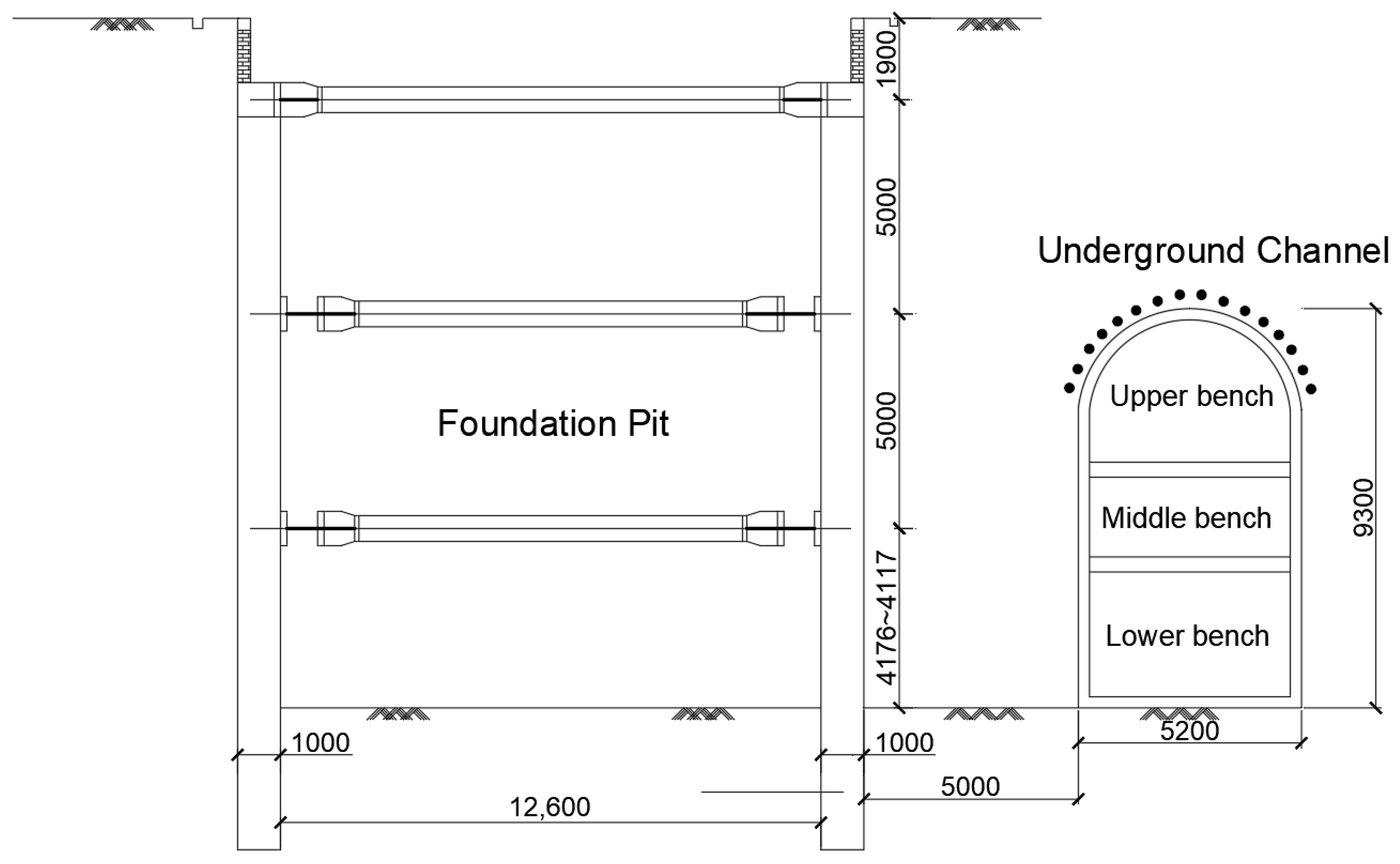
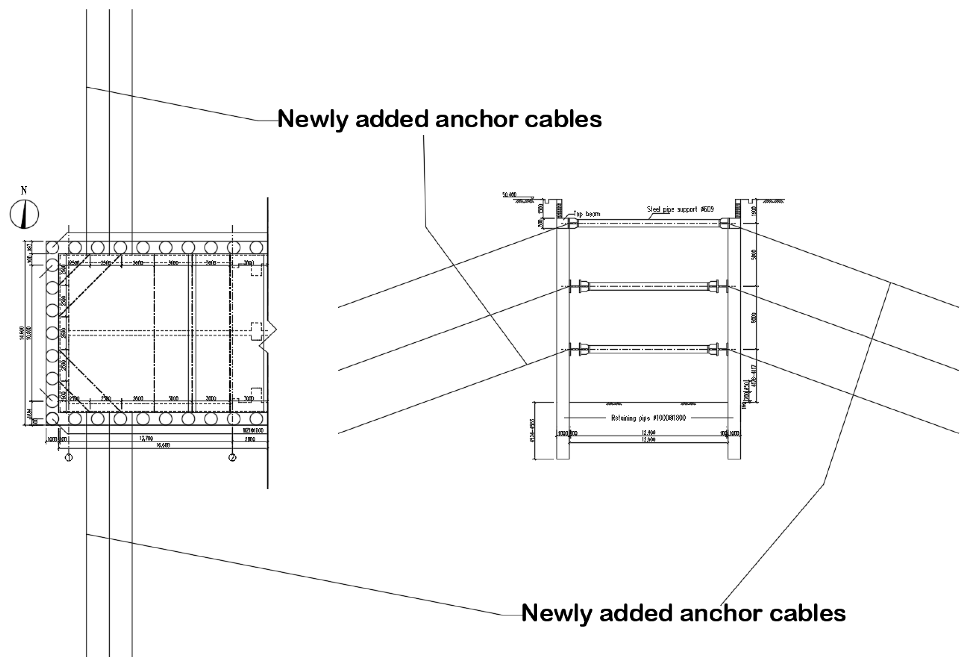
2.1. Project Description

The two adjacent excavations belong to the 17th section of Beijing Metro Line 10 Phase II project. Figure 1 shows that the deep foundation pit is located on the east side, while the underground channel lies on the west side. The foundation pit is 29.60 m long, 14.60 m wide, and 16.00 m deep. The foundation pit retaining structure consists of bored cast-in-place piles with a diameter of 1000 mm and spacing of 1800 mm and steel pipe support with a diameter of 609 mm, thickness of 12 mm, and spacing of 5000 mm.
Actually, at the beginning, there was no underground channel in the original design. The initial plan was (1) excavating the foundation pit first; (2) then constructing the bottom plate, side walls, and middle plate of the foundation pit; (3) thereafter, cutting a hole on the east side wall and bored piles of the foundation pit connecting the double-arch tunnels; and (4) at last excavating the double-arch tunnel section using the mining method. However, due to the very tight schedule, the original design was modified to add an underground channel between the double-arch tunnel and the foundation pit, which shall be excavated synchronously with the foundation pit. Once the underground channel excavation is completed, the excavation of the double-arch tunnel can start immediately without waiting for the construction of the bottom plate, side walls, and middle plate of the foundation pit to finish the project as scheduled.
The underground channel is about 35 m long, 9.30 m high, and 5.20 m wide, and its bottom plate is buried at the same depth as that of the foundation pit. The supporting structure of the underground channel consists of a grid steel frame with a spacing of 0.5 m and C20 wet-sprayed concrete with a thickness of 350 mm.
The lateral distance between the foundation pit and the underground channel ranges from a minimum of 5.00 m to a maximum of 5.40 m. It is assumed that the underground channel’s length direction is parallel to the short-side direction of the foundation pit. Figure 1 shows the engineering plan and the layout of monitoring points. Figure 2 presents a sketch map illustrating the relative positions of the underground channel and foundation pit.
With the underground channel on the east (Figure 1), anchor cables have been newly added by the design team, as shown in Figure 3. Anchor cables play a role in sharing the soil pressure on the nearby retaining piles and thus reducing the axial force of the steel pipe supports connecting them, which can help stop the deformation and rebound of the east retaining piles towards the underground channel under construction to ensure the excavation safety of the channel.

2.2. Soil Conditions

The stratum where this project is located is a typical pebble bed mainly composed of Quaternary sediments, including a small portion of fine sand and silty clay layers. The pebbles’ maximum particle size exceeds 380 mm, while the typical particle size ranges between 20 mm and 60 mm. Particles greater than 20 mm size make up about 50–70%. This pebble bed is continuously distributed. There are five layers of soil from the ground surface down, and the soil parameters of each layer, based on the site engineering geological survey report, are detailed in Table 1.
According to the survey, the highest groundwater level in the site in the past 3–5 years has been 33.0 m, while the burial depth of the underground channel bottom plate and foundation pit is 34.33 m. Moreover, no groundwater was observed during the construction process. Thus, the influence of groundwater is not considered in this study.

3. On-Site Monitoring

On-site monitoring is necessary and required to ensure the synchronous excavation safety of the underground channel and adjacent foundation pit. The retaining pile lateral displacement at the east side of the foundation pit, shown in Figure 1, has been monitored using an inclinometer with measuring points spaced 0.5 m along the pile length.
The monitoring frequency should be determined comprehensively based on the excavation situation and the change in monitoring value. According to the “Technical Code for Monitoring Measurement of Subway Engineering” [32] and design requirements, during excavation, the monitoring frequency is determined to be once per day, and the warning value for the average daily displacement rate is 2 mm/day. The maximum displacement rate cannot exceed 3 mm/day, and the maximum allowed displacement is 30 mm.
The bench cut method was adopted in the underground channel excavation, where the cross-section of the channel is divided into three benches, namely upper, middle, and lower, as shown in Figure 2, and each bench is completed in sequence with a distance of 5 m. The excavation of this project can be mainly divided into four major steps: (1) the upper bench excavation of the channel is completed, and the second layer of steel pipe support is erected; (2) the initial 4 m of the channel middle bench is excavated, and the third layer of steel pipe support is installed; (2) 20 m of the middle bench and 15 m of the lower bench of the channel are excavated, and the foundation pit excavation is completed; (4) the channel excavation is completed and the foundation pit bottom plate constructed.
Figure 4 shows the retaining pile lateral displacement across the four steps. From step 1 to step 3, it is evident that as the foundation pit and underground channel are excavated, the retaining pile lateral displacement increases rapidly due to the influence of earth pressure. Note that at step 3, the foundation pit excavation has been finished; however, the retaining pile gains remarkable deformation due to the excavation of the underground channel from step 3 to step 4. The maximum lateral displacement of the pile is 11.88 mm, far less than the monitoring warning value of 30.00 mm and about 0.067% of the foundation pit depth, indicating that the foundation pit remains in a stable and safe state.

4. Numerical Simulation and Analysis
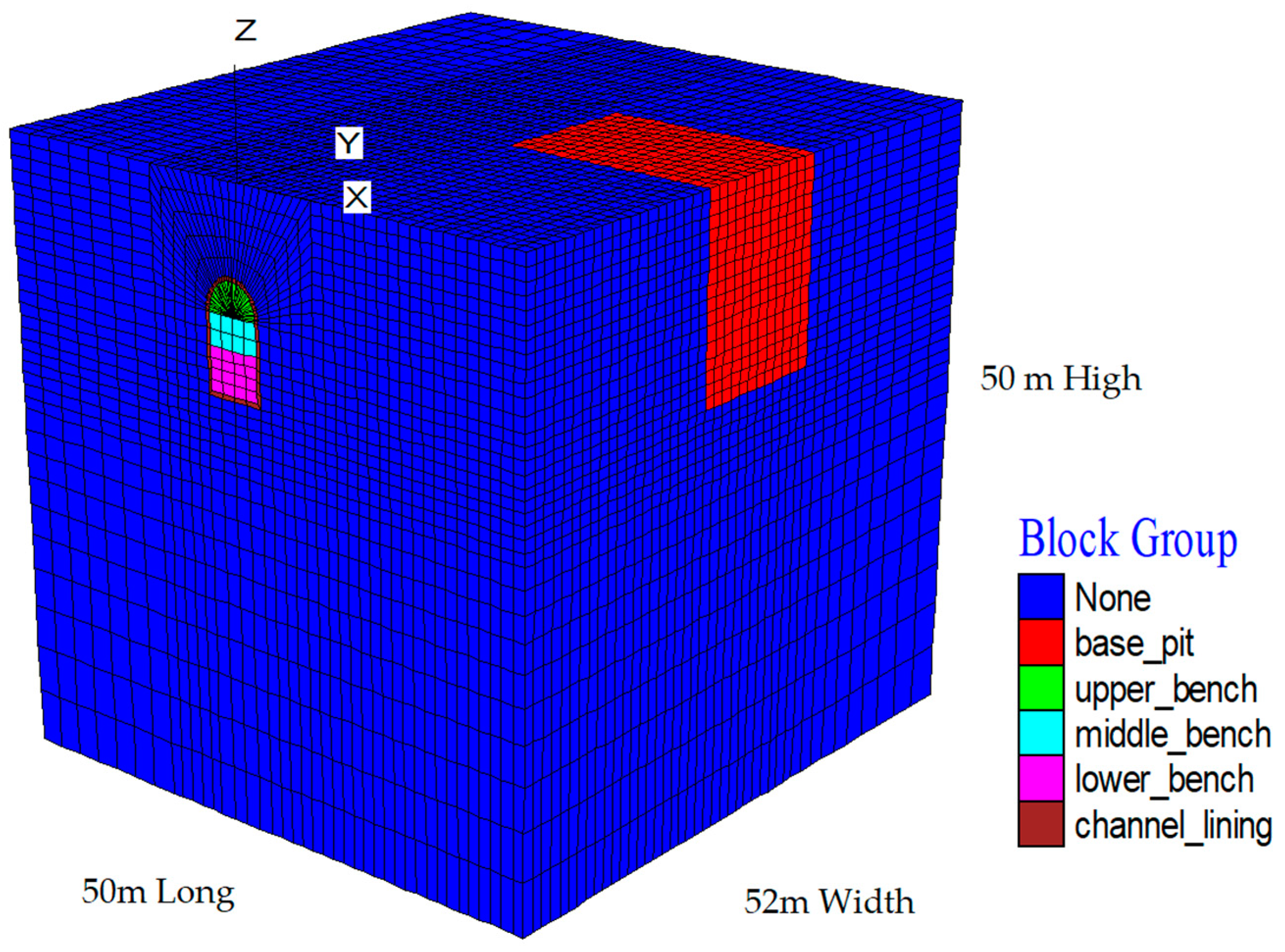
4.1. Modeling

FLAC3D finite difference calculation software was employed for modeling. Figure 5 shows the calculation model’s basic grid units.
During the modeling, the rectangular grid is mainly used to build soil elements layer by layer, the cylindrical shell grid is used to develop the circular arc lining of the upper bench of the underground channel, and the radial grid surrounding the cylinder is used to establish the soil from the top of the channel to the ground surface. To better study the channel–pit interaction, the denser grid is employed around and between the underground channel and deep foundation pit by reducing the element size in these regions. The model size is 50 m long, 52 m wide, and 50 m high, with a total of 61,992 units and 65,876 nodes. Based on the actual conditions, displacement boundary conditions are applied to the model boundaries. Horizontal constraints in the X direction are imposed on the left and right interfaces of the model, while horizontal constraints in the Y direction are applied to the front and rear interfaces. Fixed constraints are set at the bottom boundary of the model, while the top boundary remains unconstrained, representing a free surface.
The soil is directly generated using FLAC3D ordinary element in the model, and the reinforced concrete retaining piles are simulated using a “pile” structural element. In particular, the lining of the underground channel is simulated using a linear elastic solid element to better interact with the soil element around and thus affecting the foundation pit. The steel pipe supports, crown beams, and waist beams are simulated using a “beam” structural element. The bottom plate of the foundation pit is simulated using a “shell” structural element, and the excavation of the underground channel and adjacent foundation pit is flexibly realized using “empty elements”. The interaction between soil and structural elements is analyzed using the finite difference method implemented in FLAC3D, a numerical modeling tool capable of effectively simulating soil–structure interaction.
Each soil layer is assumed to be homogeneous and continuously distributed. The soil elements in the simulation are modeled as elastic-plastic materials using the Mohr–Coulomb constitutive model and incorporating elastic-plastic large deformation theory. Based on the data from design files of the underground channel and foundation pit, the physical and mechanical parameters for structural units such as reinforced concrete retaining piles, lining of underground channel, steel pipe supports, crown and waist beams, and foundation pit bottom plates are provided in Table 2.

4.2. Implementation

The simulation procedure involves the following steps: (1) model setup; (2) material property assignment; (3) boundary condition definition; (4) the initial stress state establishment; (5) excavation process; and (6) result analysis. The model’s initial stress condition is assumed to be geostatic stress, determined by the overlying soil weight. In simulation, the excavation is conducted layer by layer (about 1 m each layer) for the foundation pit and step by step (about 1 m each step) for underground channel, respectively. The simulation utilizes FLAC3D’s built-in convergence criteria to ensure equilibrium at each excavation step.

4.3. Validation

Figure 6 compares monitoring data and numerical results for the retaining pile lateral displacement at four steps. The numerical simulation yields a maximum lateral displacement of 11.47 mm, closely matching the monitored value of 11.88 mm. The maximum lateral displacement both occurs between the second and third layer of steel pipe supports, and the trends are basically consistent, indicating that the model establishment, parameter selection, and calculation method are reasonable and therefore could be used for the further analysis. Discrepancies between the monitoring data and numerical results could be attributed to human factors, rainfall, vehicles, construction machinery, time-space effect, etc., which cannot be fully considered in the numerical simulation.

4.4. Case Study

4.4.1. Excavation of the Foundation Pit with Versus Without Adjacent Underground Channel

The following analysis examines the effects of underground channel excavation on the foundation pit excavation by comparing scenarios with and without adjacent channel excavation. Figure 7 compares the retaining pile’s lateral displacement for both cases.
As can be seen from Figure 7, from step 1 to step 4, the gap between the two curves is increasing rapidly, implying that the influence of underground channel excavation on the nearby foundation pit becomes increasingly larger, especially in steps 3 and 4. The reason for this is that the underground channel excavation disrupts the soil structure around the channel and foundation pit on a larger scale compared to the case without the channel excavation, as shown in Figure 8, which affects the formation of soil arch behind the pile, as depicted in Figure 9, and weakens the soil arching effect, which finally leads to the increase in lateral soil pressure on the retaining pile, as illustrated in Figure 10, and then enlarges the lateral pile displacement. It can be observed that Figure 8a has a smaller blue area representing the soil’s downward movement than that shown in Figure 8b, and the maximum soil downward displacement increases from −6.86 mm (a) to −7.11 mm (b) due to the adjacent underground channel excavation. Note that for the case of without the underground channel, the lateral pile displacement has nearly no change from step 3 to step 4.
The underground channel excavation does increase the lateral pile displacement, as depicted in Figure 7, and the assumption of deformation and rebound of the retaining pile towards the underground channel under construction does not come true. Therefore, the design change of adding anchor cables to ensure the underground channel excavation safety is inappropriate and not necessary, which increases the construction costs and delays the foundation pit excavation.

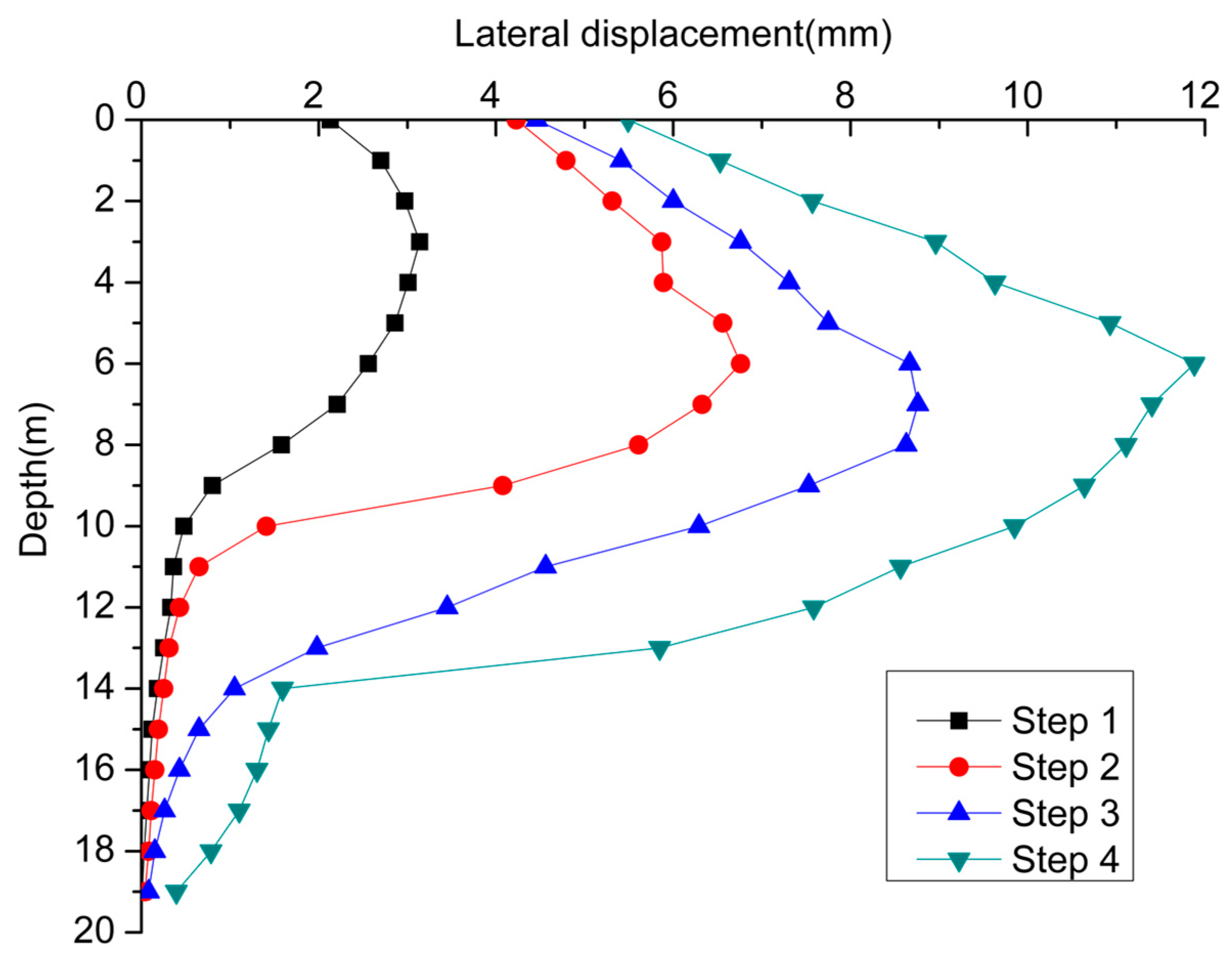
4.4.2. Effect of Excavation Sequences

To investigate the impact of different excavation sequences between the underground channel and the adjacent foundation pit, three schemes were simulated and analyzed: scheme 1, excavating the underground channel and the foundation pit synchronously as in practical; scheme 2, excavating the foundation pit first and then the underground channel; scheme 3, excavating the underground channel first and then the foundation pit.
Figure 11 compares the lateral pile displacement curves for the three schemes. The curves exhibit similar trends, with schemes 1 and 2 showing nearly identical maximum pile displacements, both larger than that of scheme 3.The reason for the differences is that in scheme 3, the underground channel is excavated first, and the disturbed soil settles partially before the foundation pit excavation begins, which would not weaken the soil arching effect behind the pile as much as that for schemes 1 and 2.

4.4.3. Effect of the Spacing

Spacing is an important factor in the interaction between the underground channel excavation and adjacent foundation pit excavation. In this study, five different spacings (5 m, 10 m, 15 m, 25 m, and 35 m) were considered. Figure 12 compares the lateral pile displacement curves for five spacings.
Figure 12 shows that as the spacing between the underground channel and the foundation pit increases from 5 m to 10 m, the lateral pile displacement decreases sharply in the middle and lower sections, aligning with the height of the underground channel. After that, as the spacing continues increasing, the lateral pile displacement decreases less and less. When the spacing reaches 35 m (about twice the depth of the channel bottom plate), the maximum lateral pile displacement is basically the same as in the case without an adjacent underground channel.

4.4.4. Effect of Existing Underground Channel on the Foundation Pit Excavation

As stated earlier, most research places great emphasis on evaluating the impact of foundation pit excavation on the displacement and safety of adjacent existing tunnels, while limited attention has been given to the influence of existing tunnels on adjacent foundation pit excavation. Figure 13 shows the comparison of lateral pile displacement for the foundation pit excavation with and without an adjacent existing underground channel. It is obvious that the existence of an adjacent underground channel does enlarge the lateral foundation pit pile displacement.
Figure 14 shows that as the foundation pit excavation progresses, the whole underground channel lining tends to float upwards, with a maximum value of 5.87 mm, which exceeds the maximum vertical displacement of 3.55 mm observed in the soil at the lining position when the foundation pit is excavated without an existing underground channel. Due to the unloading effect of the foundation pit excavation, the lateral deformation of the underground channel lining on the foundation pit side shows a rebound trend in Figure 15, with a maximum rebound value of 1.12 mm, surpassing the maximum lateral displacement of 0.93 mm in the soil. Compared to the solid and heavy soil, the existing channel is like a “hollow, elastic, light” tube and more sensitive to the foundation pit excavation. Additionally, Figure 16 indicates that the stress on the channel lining is significantly greater than on the soil due to the lining’s greater rigidity. The uplift and deformation rebound of the underground channel lining exert forces on the surrounding soil, which are transmitted and ultimately act upon the retaining pile, resulting in a final pile deformation nearly 2 mm greater than in the case without an existing underground channel.

5. Conclusions

In the current study, three-dimensional numerical simulations and field measurements were performed to investigate the interaction between the foundation pit excavation and adjacent underground channel excavation. The cases of the foundation pit excavation with and without an adjacent underground channel were studied, and the effects of excavation sequences, the spacing, and the existing underground channel on the foundation pit excavation were analyzed.
The following conclusions were drawn:
-
The underground channel excavation disrupts the soil structure around the channel and foundation pit on a larger scale, which affects the formation of soil arch behind the retaining pile and thus increased the lateral pile displacement, and the addition of anchor cables is unnecessary;
-
If conditions permit, it is the safest to excavate the underground channel first and then the foundation pit;
-
The primary interaction spacing between the two adjacent excavations is at the same depth the foundation pit depth, and when the spacing increases to twice the foundation pit depth, there is basically no interaction;
-
Compared to the solid and heavy soil, the adjacent existing underground channel is like a “hollow, elastic, light” tube and more sensitive to the foundation pit excavation, whose uplift and deformation rebound could exert a force on the surrounding soil and then enlarge the lateral pile displacement.
The findings of this study are expected to provide valuable insights for future similar projects, particularly in determining construction sequences and designing support structures for adjacent excavations.
However, current research is limited to the specific geological conditions of the site, which primarily consist of pebble layers, and does not account for groundwater effects or soil property variability. Future studies could explore synchronous excavation of adjacent underground projects in different soil types, incorporate groundwater influences, and assess the influence of synchronous excavation on the surrounding environment, piles, or nearby structures.

Author Contributions

Conceptualization, B.L. and T.L.; methodology, H.Z.; software, B.C.; validation, H.Z. and B.C.; formal analysis, H.Z.; investigation, H.Z.; resources, B.L.; data curation, L.Z.; writing—original draft preparation, H.Z.; writing—review and editing, T.L.; visualization, H.Z.; supervision, T.L. and L.Z.; project administration, B.L.; funding acquisition, H.Z. All authors have read and agreed to the published version of the manuscript.

Funding

This research was funded by the Natural Science Foundation of Fujian Province of China, grant number 2022J05099; Educational Research Program for Young and Middle aged teachers of Fujian Province of China, grant number JAT210425/B202106; and the Scientific Research Starting Foundation of Sanming University, grant number 21YG02.

Data Availability Statement

The original contributions presented in this study are included in the article. Further inquiries can be directed to the corresponding author.

Conflicts of Interest

Author Liqun Zheng was employed by the company Fujian No.1 Construction Group Co., Ltd. Author Bo Cao was employed by the company China Energy Engineering Group Guangdong Electric Power Design Institute Co., Ltd. The remaining authors declare that the research was conducted in the absence of any commercial or financial relationships that could be construed as a potential conflict of interest.

References

  1. Li, Z.F.; Yang, K.W.; Xu, X.B.; Yang, Y.J.; Jiang, Y.X.; Tong, L.; Chen, Y.M. Investigation of metro tunnel response to multiple adjacent large excavations in soft soils. Tunn. Undergr. Space Technol. 2024, 152, 105935. [Google Scholar]
  2. Zhao, X.; Wang, H.X.; Li, Z.W.; Dai, G.L.; Yin, Z.W.; Cao, S.N.; Zhou, J.L. Numerical study on the deformation of tunnels by excavation of foundation pit adjacent to the subway. Appl. Sci. 2022, 12, 4752. [Google Scholar] [CrossRef]
  3. Ma, F.H.; Li, S.L.; Wang, Q.Y. Study on the Impact of Deep Foundation Excavation of Reclaimed Land on the Deformation of Adjacent Subway Tunnels. Buildings 2024, 14, 1771. [Google Scholar] [CrossRef]
  4. Zhuang, Y.; Cui, X.Y.; Hu, S.L. Numerical simulation and simplified analytical method to evaluate the displacement of adjacent tunnels caused by excavation. Tunn. Undergr. Space Technol. 2023, 132, 104879. [Google Scholar]
  5. Qiu, J.T.; Jiang, J.; Zhou, X.J.; Zhang, Y.F.; Pan, Y.D. Analytical solution for evaluating deformation response of existing metro tunnel due to excavation of adjacent foundation pit. J. Cent. South Univ. 2021, 28, 1888–1900. [Google Scholar] [CrossRef]
  6. Liang, R.Z.; Xia, T.D.; Huang, M.S.; Lin, C.G. Simplified analytical method for evaluating the effects of adjacent excavation on shield tunnel considering the shearing effect. Comput. Geotech. 2017, 81, 167–187. [Google Scholar]
  7. Feng, G.H.; Xu, C.J.; Liang, L.J.; Tey, M.W.; Chi, M.L.; Ge, S.Q. Simplified method for evaluating the response of existing tunnel induced by adjacent excavation. Int. J. Numer. Anal. Methods Geomech. 2023, 47, 54–81. [Google Scholar]
  8. Ou, X.F.; Zhang, X.M.; Feng, H.; Zhang, C.; Wang, S.Y.; Zhou, X.S.; Wang, Z.X. Response of Metro Tunnels to Adjacent Diaphragm Wall Construction in Shenzhen Granite Residual Soil. Int. J. Geomech. 2023, 23, 05023004. [Google Scholar]
  9. Liu, B.; Shao, C.M.; Wang, N.N.; Zhang, D.W. Influenced zone of deep excavation and a simplified prediction method for adjacent tunnel displacement in thick soft soil. Appl. Sci. 2023, 13, 4647. [Google Scholar] [CrossRef]
  10. Wang, L.; Zheng, G. Protection of cement-soil reinforced regions for adjacent running tunnels during pit excavation. Chin. J. Rock Mech. Eng. 2018, 37, 3674–3685. [Google Scholar]
  11. Zheng, G.; Pan, J.; Cheng, X.S.; Bai, R.B.; Du, Y.M.; Diao, Y.; Ng, C.W.W. Use of Grouting to Control Horizontal Tunnel Deformation Induced by Adjacent Excavation. J. Geotech. Geoenviron. Eng. 2020, 146, 05020004. [Google Scholar] [CrossRef]
  12. Yang, Y.B.; Chen, C.Y.; Liu, C.; Huang, L.T.; Chen, W.; Lin, N.Y.; Cui, J.; Xie, W.D. Performance of a deep excavation and the influence on adjacent piles: A case history in karst region covered by clay and sand. Ugd. Space 2023, 8, 45–60. [Google Scholar] [CrossRef]
  13. Zhang, R.H.; Zhang, W.G.; Goh, A.T.C. Numerical investigation of pile responses caused by adjacent braced excavation in soft clays. Inter. J. Geotech. Eng. 2018, 15, 1–15. [Google Scholar]
  14. Liu, J.W.; Shi, C.H.; Cao, C.Y.; Lei, M.F.; Wang, Z.X. Improved analytical method for pile response due to foundation pit excavation. Comput. Geotech. 2020, 123, 103609. [Google Scholar]
  15. Liu, B.; Wu, W.W.; Lu, H.P.; Chen, S.; Zhang, D.W. Effect and control of foundation pit excavation on existing tunnels: A state-of-the-art review. Tunn. Undergr. Space Tech 2024, 147, 105704. [Google Scholar]
  16. Zhou, Z.; Zhen, Y.D.; Hu, J.F.; Yang, H.; Gong, C.J. Deformation analysis of shield undercrossing and vertical paralleling excavation with existing tunnel in composite stratum. J. Centr South Univ. 2023, 30, 3127–3144. [Google Scholar]
  17. Zheng, W. Analytical solution for evaluating the responses of existing pile caused by adjacent tunnel excavation. Environ. Earth Sci. 2024, 83, 495. [Google Scholar]
  18. Wu, T.H.; Gao, Y.T.; Huang, C.F.; Jin, A.B.; Zhou, Y.; Li, J.W. Horizontal mechanical responses of single pile induced by adjacent tunneling considering the effect of multiple factors based on Timoshenko Beam-Kerr foundation model. Appl. Math. Model. 2025, 140, 115885. [Google Scholar]
  19. Qi, W.Q.; Yang, Z.Y.; Jiang, Y.S.; Yang, X.; Shao, X.K.; An, H.B. Investigation on ground displacements induced by excavation of overlapping twin shield tunnels. Geomech. Eng. 2022, 28, 531–546. [Google Scholar]
  20. Liu, X.; Zhang, R.; Fang, Q.; Li, Q.Q.; Jiang, A.N.; Li, K.-C. Subgrade settlements of existing railway lines and operational parameters of shield machine induced by twin shield tunnel excavations: A case study. J. Cent. South Univ. 2024, 31, 272–287. [Google Scholar]
  21. Rodríguez, C.A.; Rodríguez-Pérez, Á.M.; López, R.; Hernández-Torres, J.A.; Caparrós-Mancera, J.J. A Finite Element Method Integrated with Terzaghi’s Principle to Estimate Settlement of a Building Due to Tunnel Construction. Buildings 2023, 13, 1343. [Google Scholar] [CrossRef]
  22. Stewart, B.R. Active and passive wall pressure induced by sorghum grain in a shallow bin. Trans. Amer. Soc. Agric. Engrs. 1972, 15, 121–125. [Google Scholar]
  23. Yue, S.Q.; Zuo, R.Y.; Lu, Z. A method for calculating active earth pressure of soil piece with a finite width between adjacent foundation pits. Rock Soil Mech. 2016, 37, 2063–2069. [Google Scholar]
  24. Shao, P.; Zhu, C.B.; Pan, J.J.; Liu, N.W. Study on the Interaction of Limited Earth Pressure and Supporting Structure between Deep Foundation Pits. Chin. J. Ugd. Space Eng. 2021, 17, 187–195. [Google Scholar]
  25. Li, S.H.; Huang, C.F.; Yao, T.J.; Li, P.F. The Influence of Non-synchronous Excavation of Twin Curved Shield Tunnels. KSCE J. Civil Eng. 2022, 26, 2456–2467. [Google Scholar]
  26. Dai, B.; Hu, Y.; Wang, H.S. Analysis and practice of influence of synchronous excavation of adjacent foundation pits in Shanghai area. Chin. J. Geotech. Eng. 2021, 43, 129–132. [Google Scholar]
  27. Shi, H.Y.; Ge, C.L.; Liu, Z.; Tang, J. Study on Interaction of Two Adjacent Excavations Constructed Simultaneously. Chin. J. Ugd. Space Eng. 2015, 11, 183–188. [Google Scholar]
  28. Shi, H.; Jia, Z.L.; Wang, T.; Cheng, Z.Q.; Zhang, D.; Bai, M.Z.; Yu, K. Deformation Characteristics and Optimization Design for Large-Scale Deep and Circular Foundation Pit Partitioned Excavation in a Complex Environment. Buildings 2022, 12, 1292. [Google Scholar] [CrossRef]
  29. Wang, S.J.; Wang, W.T.; Yang, H.; Zhao, D.B.; Liu, Y. Study on the influence of adjacent double deep foundation pit excavation sequence on existing tunnel deformation based on HSS constitutive model. Appl. Sci. 2024, 14, 3626. [Google Scholar] [CrossRef]
  30. Tan, Y.; Lu, Y.; Wang, D.L. Synchronous-cross zoned excavation of the oversized basement of Shanghai International Financial Centre by combination of bottom-up and top-down methods: Structural and geotechnical behaviors. Tunn. Undergr. Space Tech. 2024, 153, 106023. [Google Scholar]
  31. Tan, Y.; Lu, Y.; Wang, D.L. Interactive behaviors of four closely spaced mega excavations in soft clays: Case study on an excavation group in Shanghai, China. Tunn. Undergr. Space Technol. 2023, 138, 105186. [Google Scholar] [CrossRef]
  32. Beijing Municipal Commission of Housing and Urban-Rural Development. Technical Code for Monitoring Measurement of Subway Engineering(DB11/490-2007)[S]; China Communications Press: Beijing, China, 2007.
Disclaimer/Publisher’s Note: The statements, opinions, and data contained in all publications are solely those of the individual author(s) and contributor(s) and not of MDPI and/or the editor(s). MDPI and/or the editor(s) disclaim responsibility for any injury to people or property resulting from any ideas, methods, instructions, or products referred to in the content.
Figure 1. The engineering plan and monitoring point layout.
Buildings 15 01110 g001
Figure 2. Sketch map of the relative position of the underground channel and foundation pit.
Buildings 15 01110 g002
Figure 3. Location of newly added anchor cables: engineering plan (Left) and sectional view (Right).
Buildings 15 01110 g003
Figure 4. Lateral displacement curves of the retaining pile across four steps.
Buildings 15 01110 g004
Figure 5. Mesh of geometry.
Buildings 15 01110 g005
Figure 6. Comparison of monitoring data and numerical results for lateral pile displacement.
Buildings 15 01110 g006
Figure 7. Comparison of lateral pile displacement for the cases of with and without adjacent underground channel.
Buildings 15 01110 g007
Figure 8. Comparison of soil vertical displacement for the cases of without (a) and with adjacent underground channel (b).
Buildings 15 01110 g008
Figure 9. Sketch map of soil arch behind the retaining pile.
Buildings 15 01110 g009
Figure 10. Comparison of lateral soil pressure on the retaining pile for cases of with and without adjacent underground channel.
Buildings 15 01110 g010
Figure 11. Comparison of lateral pile displacement for three schemes.
Buildings 15 01110 g011
Figure 12. Lateral pile displacement for five spacings.
Buildings 15 01110 g012
Figure 13. Comparison of lateral pile displacement with and without adjacent existing underground channel.
Buildings 15 01110 g013
Figure 14. Vertical displacement contour of underground channel lining (Left) for the case with existing underground channel and contour of the soil at the position of channel lining for the case without existing underground channel (Right).
Buildings 15 01110 g014
Figure 15. Lateral displacement contour of underground channel lining (Left) for the case with existing underground channel and contour of the soil at the position of channel lining for the case without existing underground channel (Right).
Buildings 15 01110 g015
Figure 16. Contour of normal stress in the X direction on underground channel lining (Left) for the case with existing underground channel and on the soil at the position of channel lining for the case without existing underground channel (Right).
Buildings 15 01110 g016
Table 1. List of soil parameters.
Soil Thickness (m)Density (g/cm3)Bulk
Modulus (Mpa)
Shear Modulus (Mpa)Internal Friction Angle (°)Cohesion
(kPa)
Earth fill31.806.673.081015
Silty fine sand22.0217.369.92300
Pebble142.1032.7422.54450
Silty clay31.957.943.882220
Pebble102.1537.6329.41520
Table 2. Design parameters for structural units.
Structural UnitsDensity (kg/cm3)Elastic Modulus (GPa)Poisson’s Ratio
RC retaining pile2500300.2
Lining of underground channel250010.50.25
Steel pipe support78002000.3
Crown and waist beams2500300.2
Foundation pit bottom plate2500300.2
Disclaimer/Publisher’s Note: The statements, opinions and data contained in all publications are solely those of the individual author(s) and contributor(s) and not of MDPI and/or the editor(s). MDPI and/or the editor(s) disclaim responsibility for any injury to people or property resulting from any ideas, methods, instructions or products referred to in the content.

