Article

The Structural Configuration and Mechanical Performance of a New Cable-Supported Reciprocal Structure

1
School of Civil Engineering and Architecture, Henan University, Kaifeng 475004, China
2
Department of Civil, Construction and Environmental Engineering, University of Alabama at Birmingham, Birmingham, AL 35294, USA
*
Authors to whom correspondence should be addressed.
Buildings 2025, 15(7), 1006; https://doi.org/10.3390/buildings15071006
Submission received: 12 February 2025 / Revised: 11 March 2025 / Accepted: 20 March 2025 / Published: 21 March 2025
(This article belongs to the Section Building Structures)

Abstract

Reciprocal structures represent a category of spatial structural systems characterized by mutually supporting connections between components, which are primarily employed in roof systems and spatial frameworks. Insufficient stiffness is a critical challenge for the practical application of reciprocal structures in engineering. This study introduces a new cable-supported reciprocal structure, which integrates rigid beams and flexible cables through struts, inspired by the construction principles of beam string structures. By optimizing the force transfer path, the overall performance of the structure is improved. Through finite element analysis, a comprehensive investigation was conducted on the static behavior and parametric analysis of this new reciprocal structure. The research results show that the rational determination of key parameters, including the rise/span ratio, strut height, and cable length, demonstrates significant efficacy in reducing the maximum displacement of this new reciprocal structure under uniformly distributed load. The stiffness of the new cable-supported reciprocal structure increases by 17% compared to that of the general reciprocal structure, while the total steel consumption decreases by 12%. The proposed new cable-supported reciprocal structure presents an innovative and viable configuration within the domain of reciprocal structures.

1. Introduction

The reciprocal structure is a new type of spatial structure characterized by the overlapping of components [1]. Due to their unique connection method, reciprocal structures feature esthetically pleasing shapes, simple joints, and ease of construction [2]. Due to their short construction periods, simple construction, and low technical requirements, reciprocal structures are commonly used in roof ceilings, bridges, exhibition halls, post-disaster shelters, and other structural forms [3].
However, the development of reciprocal structures faces several challenges, such as difficulty in form finding, limited types of configurations, low stiffness, and insufficient research on mechanical performance [4]. In response to these issues, experts and scholars both domestically and internationally have conducted research on the configuration methods and mechanical performance of reciprocal structures. Romain Mesnil et al. [5] transformed the reciprocal configuration into a quadratic optimization problem under linear constraints through the translation method, which is especially suitable for the reciprocal structures generated by quadrilateral meshes. Fan et al. [6] analyzed the kinematic mechanism of the mechanical model of the Wooden Rainbow Bridge and proposed an improved joint connection method to achieve compatibility of structural displacement of the bridge under both upward and downward loads. However, its mechanical properties have not been investigated by experimental testing or the finite element method. Maziar Asefi et al. [7] established a framework for designing reciprocal structures and found that small changes in any parameter of reciprocal structures would affect their overall structural configuration, but discussions about structural analyses were not investigated. Andry Widyowijatnoko et al. [8] combined the tensegrity structure and the reciprocal structure and proposed a reciprocal–tension(rection) structure, a concept that serves as a valuable reference for the present study. Su et al. [9] separated the bars of the reciprocal unit so that the bars of the reciprocal structure reached the same position of a tensegrity structure and formed the reciprocal tensegrity structure. Based on small-sized topologically interlocking prefabs, Maciej Piekarski [10] investigated their application in floor slab systems, demonstrating the advantages of this system in terms of both structural performance and esthetic value. Wu Yue et al. [11] analyzed the mechanical performance of a suspended reciprocal grid structure and verified its rationality by comparing it with the general reciprocal structure, though this configuration is only applicable to reciprocal structures with medium and small rise/span ratios. Cheav Por Chea et al. [12] established a reciprocal structure with pultruded glass fiber-reinforced polymer members and studied its mechanical properties, finding that the boundary type has a significant influence on the overall deformation of the reciprocal structure. Based on the 2005 Serpentine Gallery pavilion, Beatriz del Río-Calleja [13] reviewed reciprocal frame structures documented in Western architectural history, emphasizing the significance of studying historical building solutions. Maciej Piekarski [14] carried out a static analysis on structural grillages made of steel reciprocal beams and concluded that the structural grillages with articulated joints not only have excellent load-bearing capacity but are also convenient for construction. Xia et al. [15] carried out the reciprocal configuration of the curved rod based on the optimization algorithm and concluded that the addition of the curved rod was conducive to reducing the types of rods and making the reciprocal structure more adaptable to the curved shape. However, it is not conducive to the practical application of the reciprocal structure. Asli Agirbas [16] proposed a semi-automated model based on deep learning, which can convert 2D sketches into 3D reciprocal structural models. Based on 62 practical cases of reciprocal structures, Xu et al. [17] divided reciprocal structures into two categories, node type, and unit type, and gave the parameter control prediction interval of reciprocal structures. Xia et al. [18] introduced the generalized displacements at the hinge point to describe the displacements of the nodes at the beam ends, effectively reducing the computational degrees of freedom of the reciprocal structure. Two numerical examples, a space L-shaped articulated reciprocal rigid frame and a reciprocal configuration transformed from the 36 types of Archimedes paving, were used to validate the effectiveness of the method in calculating the dynamic behavior and seismic performance of reciprocal structures. Cristina Martínez Arias [19] used analytical and optimization methods to develop a new form-finding approach to transformable reciprocal frame structures, parameterized them, and applied the parameterized structures to the design of surfaces of variable geometry via newly created geometric software. In conclusion, although significant progress has been made in the study of reciprocal structures, relatively few studies have focused on structural stiffness. Additionally, several of the studies mentioned above combine tension with the reciprocal structure, and utilizing tension to enhance the stiffness of the reciprocal structure in a rational manner holds significant potential.
The wooden Rainbow bridge in Zhang Zeduan’s painting, named Qingming shang he painting, is a traditional reciprocal structure in China [6], as shown in Figure 1. The traditional reciprocal structures mostly use wood, which is beautiful in appearance and allows for rapid lap joint formation, but the problem of insufficient flexural stiffness of the members is more prominent. In this study, a new cable-supported reciprocal structure is proposed, and the finite element analysis of the structure model with a span of 27.3 m is conducted to verify the feasibility and effectiveness of the configuration. In contrast to previous studies, the new cable-supported reciprocal structure integrates struts and cables into each bar along the span, significantly improving the bending performance of these bars. By optimizing the behavior of localized components, this approach enhances the overall structural performance.

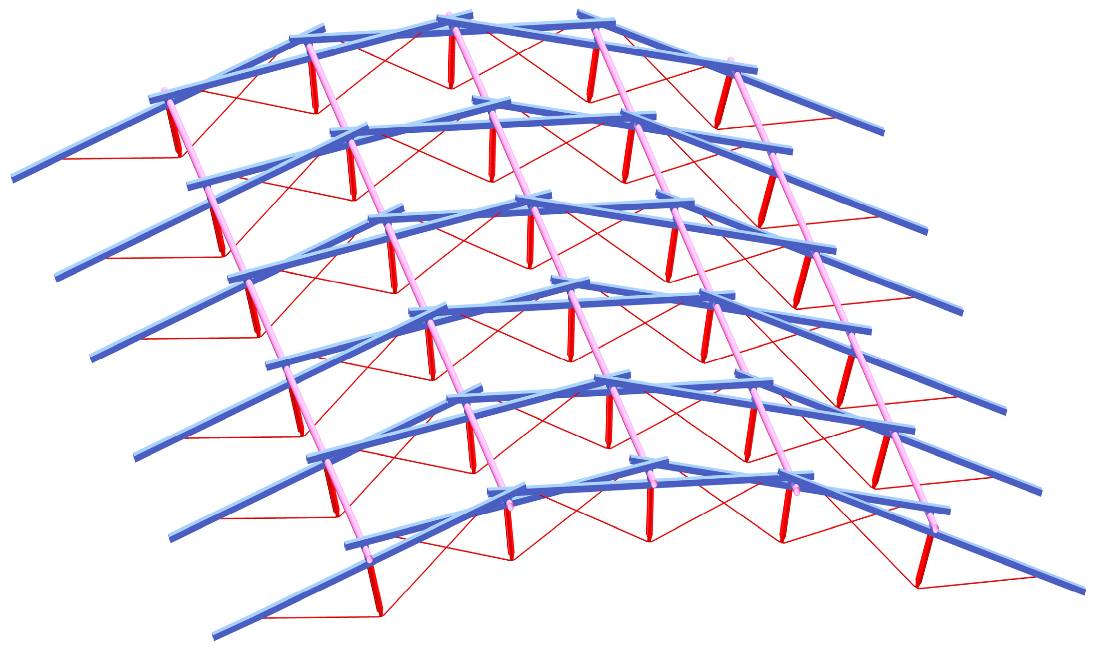
2. Structural Configuration

2.1. Basic Configuration

Leonardo da Vinci [20] drew the earliest sketch model of a tessereil pont in the manuscript Codex Atlanticus, which features wooden transverse and longitudinal bars lapped together, with the bars themselves exhibiting low bending stiffness, as shown in Figure 2.
In contrast, the beam string structure is a self-balancing system made up of flexural compression members, struts, and lower chord tension cables. By applying pre-tension forces in the cables, this structure improves the stress performance of flexural compression members. Therefore, in this paper, a new large-span cable-supported reciprocal structure is proposed by drawing on the mechanical principle of beam string structure and introducing struts and cables into the structural model of the tessereil pont. The overall configuration of the structure is shown in Figure 3.

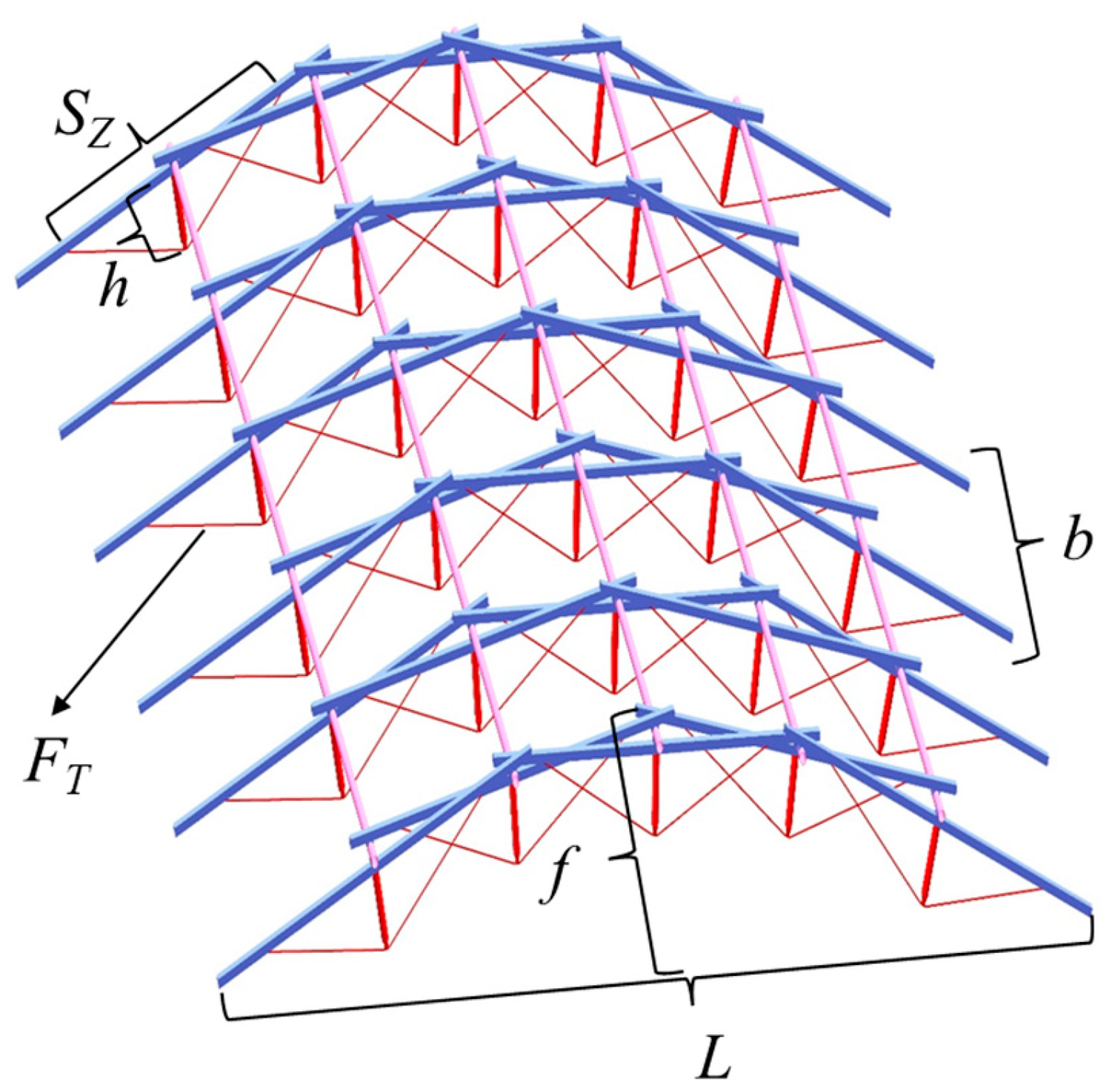
2.2. Parameter Definitions of the Basic Elements

The design of a reciprocal structure’s configuration is a highly complex process, where even small changes in the parameters can result in an alteration to the overall structure. Despite this complexity, the reciprocal structure can be constructed by the diversity of simple basic elements. Taking the three-bar reciprocal structure as an example, as shown in Figure 4a, the parameters defining the cable-supported reciprocal basic elements are as follows:
(1)
The length of the basic bar l. The member of the basic reciprocal element formed by pair-to-pair connected members is called the basic bar. Typically, the design of the basic bar uses members with the same cross-section.
(2)
Strut height h. The member that connects the cable to the basic bar and is positioned in the middle and lower part of the basic bar is called the strut. The strut height is one of the parameters of the cable-supported reciprocal basic element.
(3)
The cable projected length SZ. The cable projected length along the axis of the basic bar is called the cable projected length. The cable projected length is one of the parameters of the cable-supported reciprocal basic element and is generally smaller than the length of the basic bar l.
(4)
The engagement length le and the engagement coefficient λ. The distance between the point where a basic bar contacts an adjacent basic bar is called the engagement length. The engagement coefficient is a proportionality factor that expresses the relationship between the engagement length and the length of the basic bar. λ = l e / l .
(5)
The eccentricity value e. The spatial distance between the center axes of adjacent basic bars is called the eccentricity value. Specifically, when the basic bars have a circular cross-section and are in lap contact with each other, the eccentricity value is the sum of the radii of the two basic bars.
(6)
Basic element direction. Fix the center of the basic element and increase the engagement length. If the contact point between the basic bars rotates counterclockwise, the basic element is referred to as the “left type”. If the contact point between the basic bars rotates clockwise, the basic element is referred to as the “right type”, as shown in Figure 4b.

2.3. Parameter Definitions of the Overall Model

The configurational design of reciprocal structures is closely linked to the evaluation of overall model parameters. To achieve a more rational design for the new cable-supported reciprocal structure, two key overall model parameters—the rise/span ratio f/L and the longitudinal spacing b—are introduced. These parameters are combined with the strut height h, cable projected length SZ, and prestressing force of the cable FT to produce the constitutive design of the overall model. The mechanical performance of the model corresponding to each of these parameters is then analyzed, and the structural model with the optimal performance is selected, and these 5 parameters are shown in Figure 5.

2.4. Basic Design Flow

The basic design process of the new cable-supported reciprocal structure is shown in Figure 6, which is outlined as follows: (1) Determine the initial values and initial ranges for the rise/span ratio f/L, longitudinal spacing b, strut height h, cable projected length SZy and prestress FT, based on design requirements. (2) Establish the basic components of the structure, such as the rectangular crossbars, struts, and cables, in the ’Part’ module of SolidWorks based on the determined parameters. (3) Import the aforementioned components into the ’Assembly’ module in SolidWorks 2021 and assemble them into sub-assemblies. (4) Further assemble the sub-assemblies along with the longitudinal circular bars to construct the required solid model. (5) Extract the axes of the main components from the solid model and locate the coordinates of all joints by importing the solid model into SpaceClaim 2022. (6) Correct the joint coordinates and construct the line body model based on the solid model. (7) Conduct a static analysis using ABAQUS/Standard 2023, where material properties, loading conditions, and boundary constraints are defined. Then, analyze the finite element model to obtain the mechanical performance of the model under the corresponding initial parameters. (8) Select the structural model with optimal engineering applicability, esthetic appeal, and superior mechanical performance in accordance with relevant codes.

3. Static Analysis

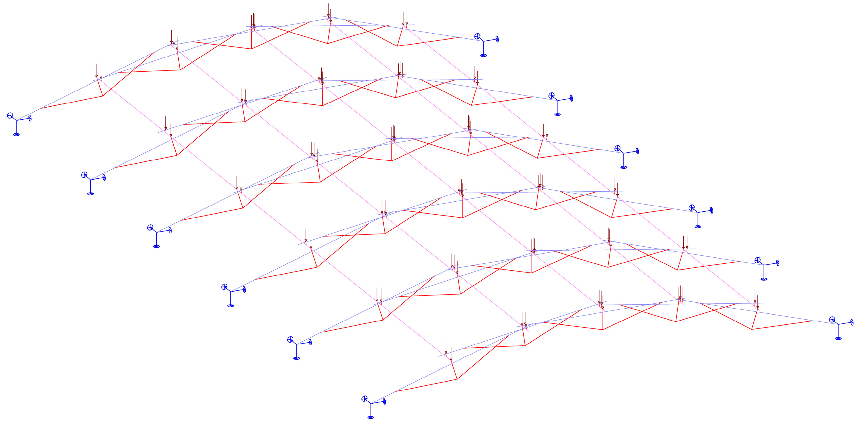
3.1. ABAQUS Analysis Model

3.1.1. Model Parameter

The focus of the finite element analysis for the new cable-supported reciprocal structure is on the lap contact between the upper bars. To simulate the lap force transfer contact between the bars, this study employs the method of introducing rigid, small, short bars along the common vertical line of the bars [11,18,21].
The finite element analysis model is shown in Figure 7, featuring a structural span of 27.3 m and a rise/span ratio of 1/8. The rectangular crossbar has a cross-sectional dimension with a width of 150 mm, height of 200 mm, and thickness of 6 mm, and a length of 10 m; the circular bar has a cross-sectional diameter of 150 mm and a thickness of 6 mm, and a length of 25.4 m; the cable’s effective cross-sectional area is 707 mm2, with a length of 8.4 m and a prestress is 150 kN; the circular strut has a cross-sectional diameter of 150 mm and a thickness of 6 mm, and a length of 1.25 m; the short bar has a cross-sectional diameter of 50 mm and a length of 175 mm.

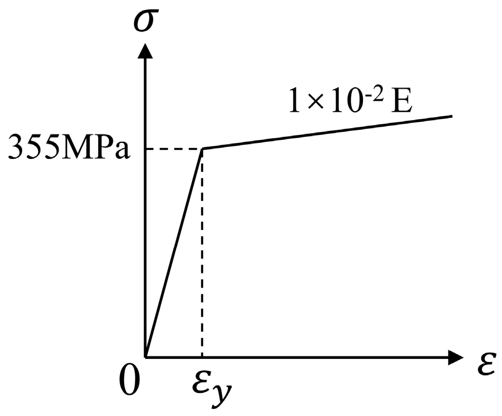
3.1.2. Material Properties

In the numerical simulation process, the rectangular crossbar, longitudinal circular bar, and strut are made of Q355 steel, with a yield strength of 355 MPa, Young’s modulus of 206 GPa, and a Poisson’s ratio of 0.3. The bilinear kinematic hardening model is adopted, with a tangent modulus of 0.01E in the reinforcement stage, as shown in Figure 8. The yield strength of the cable is 1670 MPa, its Young’s modulus is 190 GPa, the Poisson’s ratio is 0.3, and the coefficient of linear thermal expansion is 1.2 × 10⁻⁵. The Young’s modulus of the short bar is 20,600 GPa, and its Poisson’s ratio is 0.

3.1.3. Element Type

The members of the new cable-supported reciprocal structure are simulated in ABAQUS using two types of elements. Rectangular crossbars, longitudinal circular bars, and short bars are simulated using the B32 beam element. The struts and cables are simulated using the T3D2 truss element.
The beam element is a one-dimensional line element in three-dimensional space that can deform in axial stretch, bending, and torsion but not within its own plane. The B32 beam element in ABAQUS is a three-node quadratic beam element with six degrees of freedom at each node. To more accurately simulate the characteristics of reciprocal structure bars that lap over each other, the degrees of freedom at both ends of the short bars around their own axis are released by the release keywords. The truss element in ABAQUS is also a one-dimensional line element that can only deform in axial stretch. The T3D2 truss element is a two-node linear truss element with three degrees of freedom at each node. The cable is set as a tension-only element, with no compression allowed.

3.1.4. Loads and Boundaries

The structural load is a uniform load applied across the entire span, consisting of a dead load is 0.2 kN/m2 and a live load is 0.5 kN/m2. The total load is 1 kN/m2, which is uniformly distributed across the lap joint.
The prestress in the cable is applied using the thermal control method, as described by the following equation:
F T = α E A T
T = T 0 T 1
where F T is the prestress, α is the coefficient of linear thermal expansion, E is the Young’s modulus, A Is the cross-sectional area, T is the temperature difference, T 0 is the initial temperature, and T 1 is the final temperature.
Provide fixed supports at the outermost nodes of the span.

3.2. Static Analysis Results

Static analyses were conducted using ABAQUS/Standard on both the general reciprocal structure and the new cable-supported reciprocal structure, each subjected to a uniform load of 1 kN/m2. Both structures had identical superstructure configurations. The results of the static analysis are shown in Figure 9 and Figure 10, where the bar displacement refers to the vertical displacement of the bar, with positive values indicating upward movement.
From the figures, it can be observed that the displacement distributions of both the general reciprocal structure and the new cable-supported reciprocal structure are symmetric, with central symmetric, under the uniform load, the maximum displacements occur at the longitudinal circular bar at the mid-span and at the edge span of the structural model, respectively, with the values being −56 mm and −46 mm. The maximum stresses of both structural models occur at the node position where the second longitudinal circular bar is connected to the outermost crossbar, with the values being 334 Mpa and 298 Mpa. This may be due to the absence of outboard supporting bars.

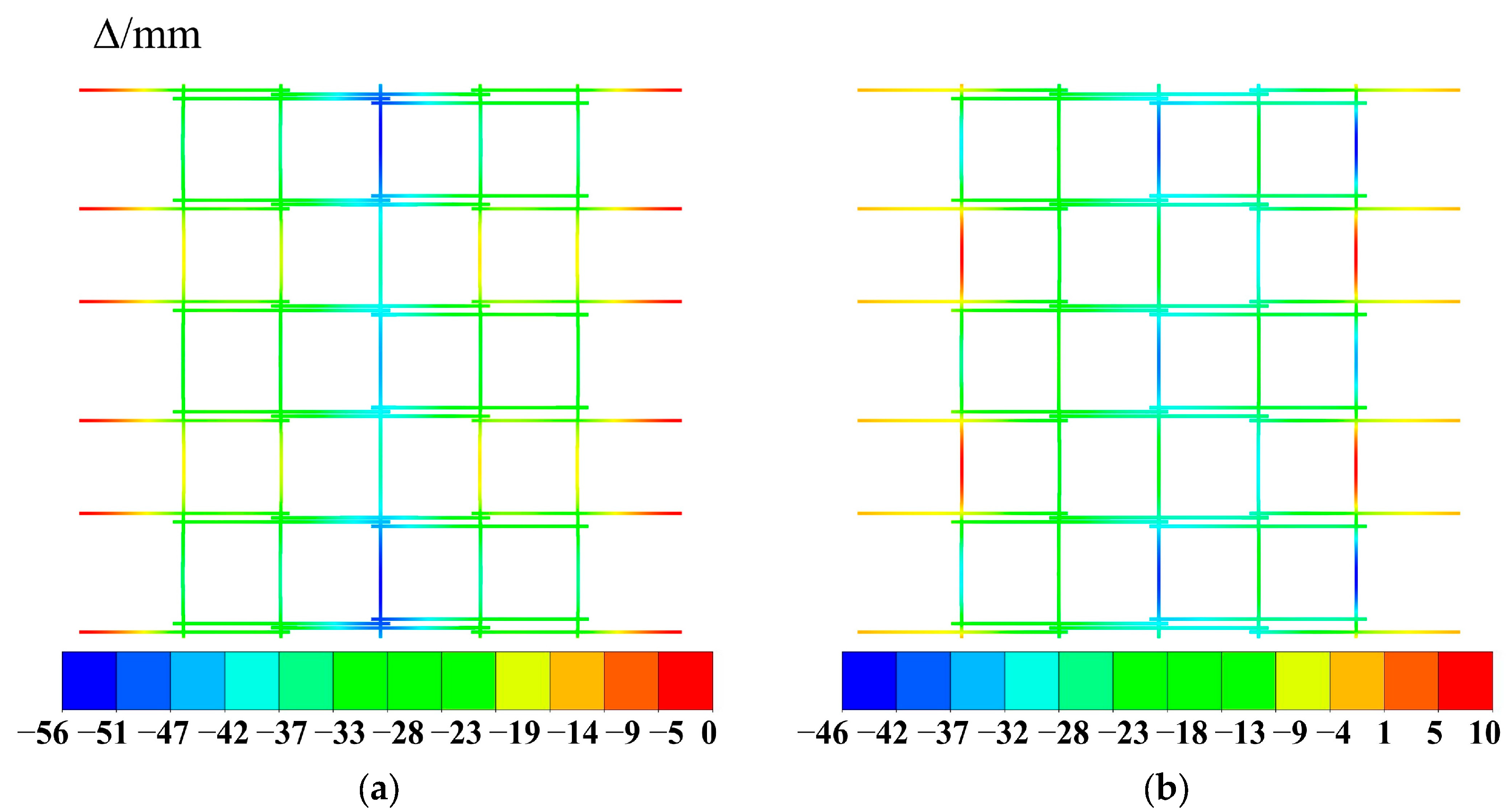
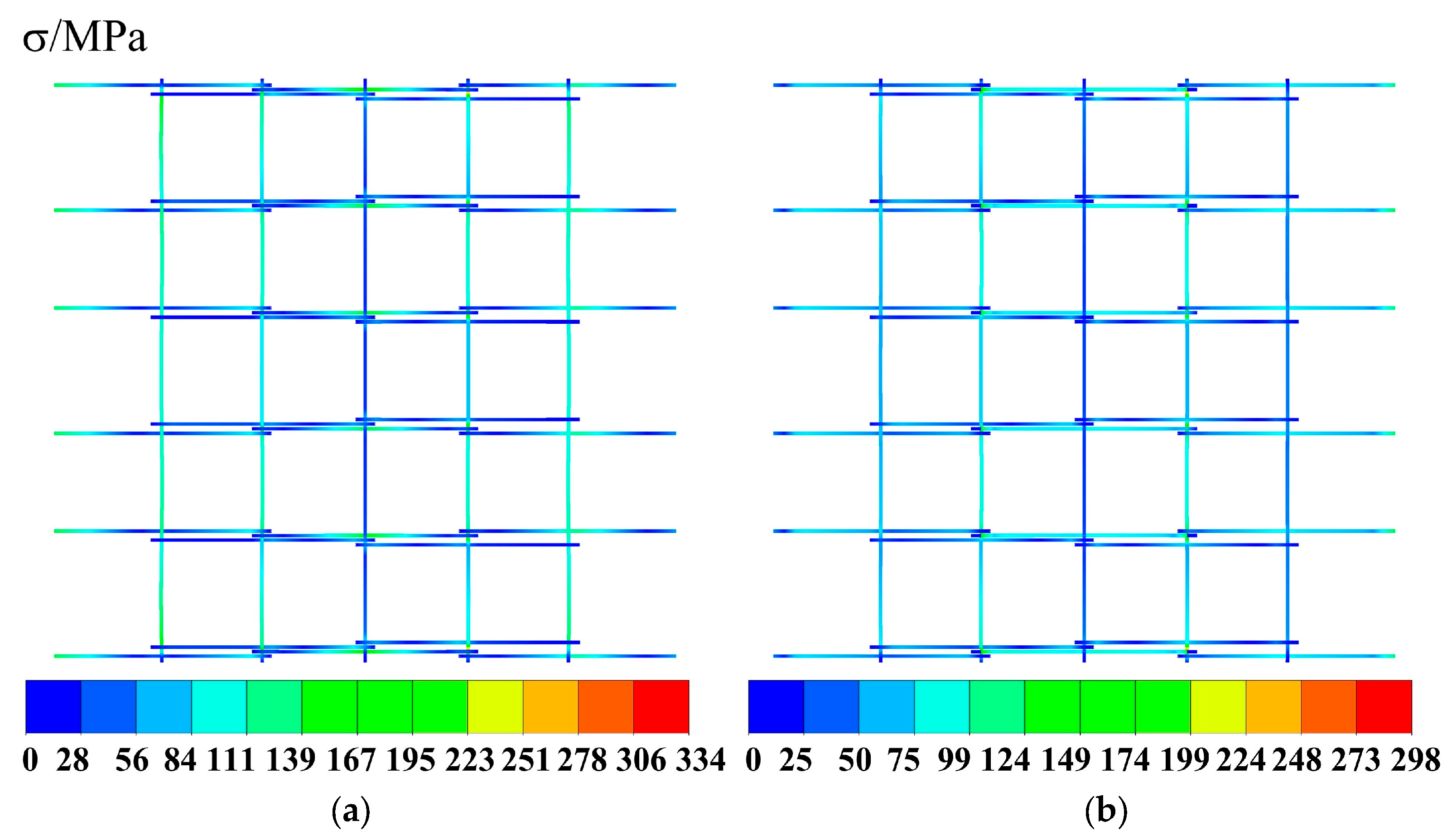
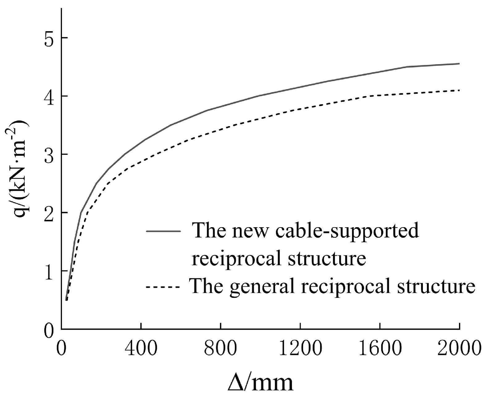
3.3. Comparative Analysis

The cross-sectional dimensions of the general reciprocal structure and the new cable-supported reciprocal structure and the total mass of each type of component are shown in Table 1, and a comparative analysis of the two structures is conducted in four key aspects: mass, maximum displacement, maximum stress, and maximum bearing capacity. The results are shown in Table 2. The load-displacement curves of the two structures are shown in Figure 11.
As shown in Table 2, the mass of the general reciprocal structure is 16.25 t, while the mass of the new cable-supported reciprocal structure is 14.54 t, representing a reduction of 12%. The maximum displacement of the general reciprocal structure is 56.0 mm, compared to 46.3 mm for the new cable-supported reciprocal structure, which is a reduction of 17%. The maximum stress of the general reciprocal structure is 334 MPa, while the new cable-supported reciprocal structure is 298 MPa, showing an 11% reduction. The maximum bearing capacity of the general reciprocal structure is 4.02 kN/m2, whereas that of the new cable-supported reciprocal structure is 4. 56 kN/m2, reflecting a 13% increase.
Based on the above analysis, the following conclusions can be drawn: compared to the general reciprocal structure, the new cable-supported reciprocal structure is not only lighter in mass, smaller in displacement, and more reasonable in stress distribution but also exhibits higher maximum bearing capacity, better esthetic appearance, and faster construction speed, all of which make it capable of meeting the engineering requirements.

4. Parametric Analysis

To verify the rationality and validity of the constitutive parameters, this section discusses the effects of the rise/span ratio, longitudinal spacing, strut height, cable projected length, and prestress on the maximum displacement and maximum stress of the structure. A parametric analysis is performed on the structural model with varying rise/span ratios, longitudinal spacings, strut heights, cable projected lengths, and prestress levels based on the constitutive parameters in Section 3.1.

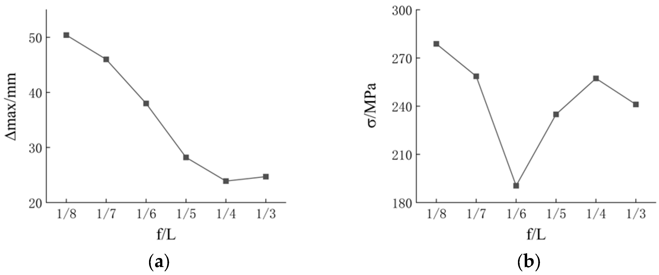
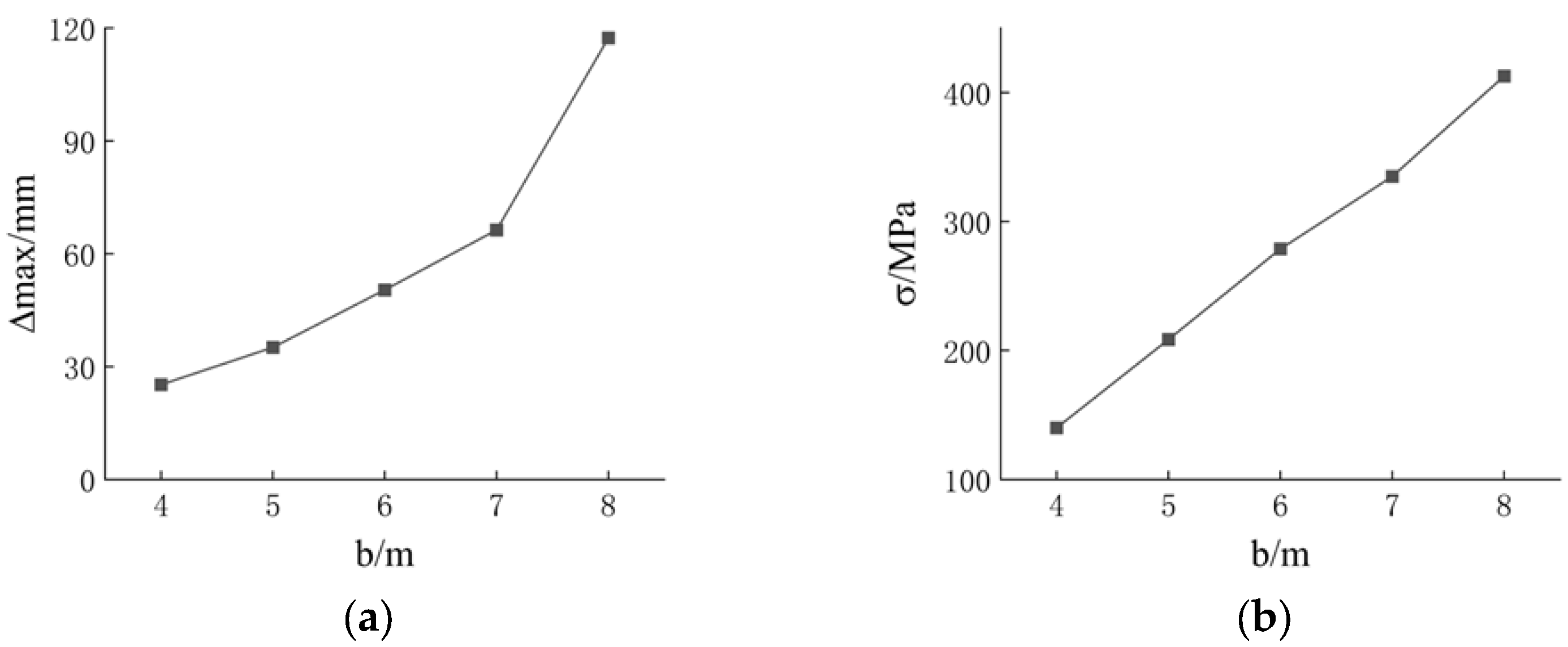
4.1. Rise/Span Ratio Analysis

A parametric analysis is conducted on the structural model with rise/span ratios ranging from 1/8 to 1/3 to investigate the effect of different rise/span ratios on the maximum displacement and maximum stress of the structure, with the results shown in Figure 12. All parameters, except for the rise/span ratio, are consistent with the model in Section 3.1. In this study, the variation in the rise/span ratio is controlled by adjusting the engagement length le of the bars.
It can be observed that the new cable-supported reciprocal structure is highly sensitive to changes in the rise/span ratio. As the rise/span ratio increases, the maximum displacement of the structure decreases, while the maximum stress exhibits a trend of initially decreasing and then increasing. This is likely because, as the rise/span ratio increases, the total load of the structure decreases due to the change in the area of the effective load. However, both the maximum displacement and the maximum stress satisfy the specification requirements under conventional loading conditions. Therefore, the engineering applicability of the new cable-supported reciprocal structure is excellent.

4.2. Longitudinal Spacing Analysis

The longitudinal spacing b refers to the distance between the supports of the new cable-supported reciprocal structure, measured along the direction perpendicular to both the span and the rise in the structure. A parametric analysis is conducted on the structural model with longitudinal spacings ranging from 4 to 8 m to investigate the effect of different longitudinal spacings on the maximum displacement and maximum stress of the structure, with the results shown in Figure 13. All parameters, except for the longitudinal spacing, are consistent with the model in Section 3.1.
It can be observed that the new cable-supported reciprocal structure is highly sensitive to changes in longitudinal spacing. As the longitudinal spacing decreases, both the maximum displacement and the maximum stress of the structure reduce. This is likely due to insufficient vertical support for the longitudinal bars. However, for the same total length, the mass of the structure increases as the longitudinal spacing decreases. Additionally, the length-to-diameter ratio of the longitudinal circular bar decreases with the reduction in longitudinal spacing. The structure can still meet the code requirements when the longitudinal spacing is 6 m. Therefore, the optimal longitudinal spacing of the new cable-supported reciprocal structure is 6 m.

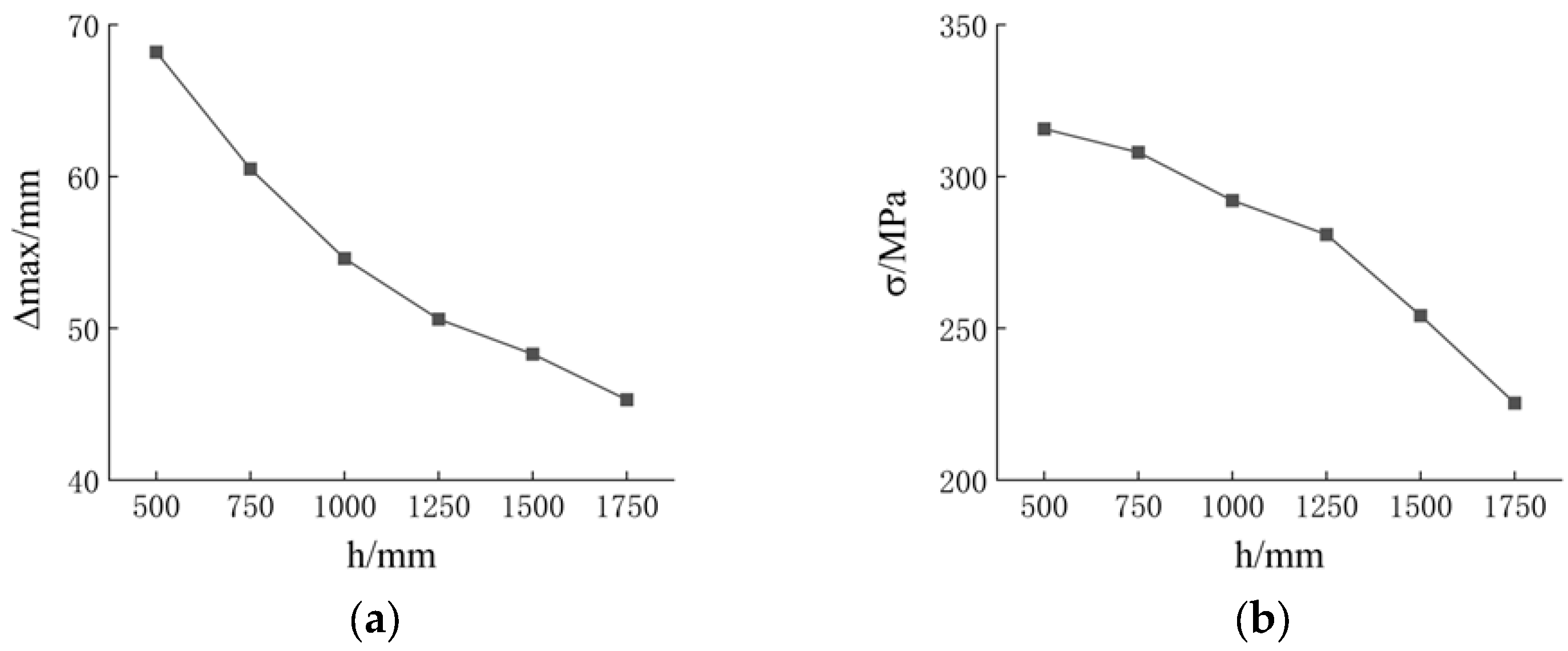
4.3. Strut Height Analysis

The strut height h refers to the length of the component that connects the rectangular crossbar and the cable in the new cable-supported reciprocal structure. A parametric analysis is conducted on the structural model with strut heights ranging from 500 to 1750 mm to investigate the effects of different strut heights on the maximum displacements and maximum stresses of the structure, with the results shown in Figure 14. All parameters, except for the strut heights, are consistent with the model in Section 3.1.
It can be observed that the new cable-supported reciprocal structure is less sensitive to changes in strut height. As the strut height increases, both the maximum displacement and the maximum stress of the structure decrease. This is likely due to the increased support force from the strut on the flexural compression member, which gradually reduces the impact of the applied load. However, a larger strut height also leads to an increase in the overall mass of the structure. Therefore, the strut height of the new cable-supported reciprocal structure is chosen to be 1250 mm.

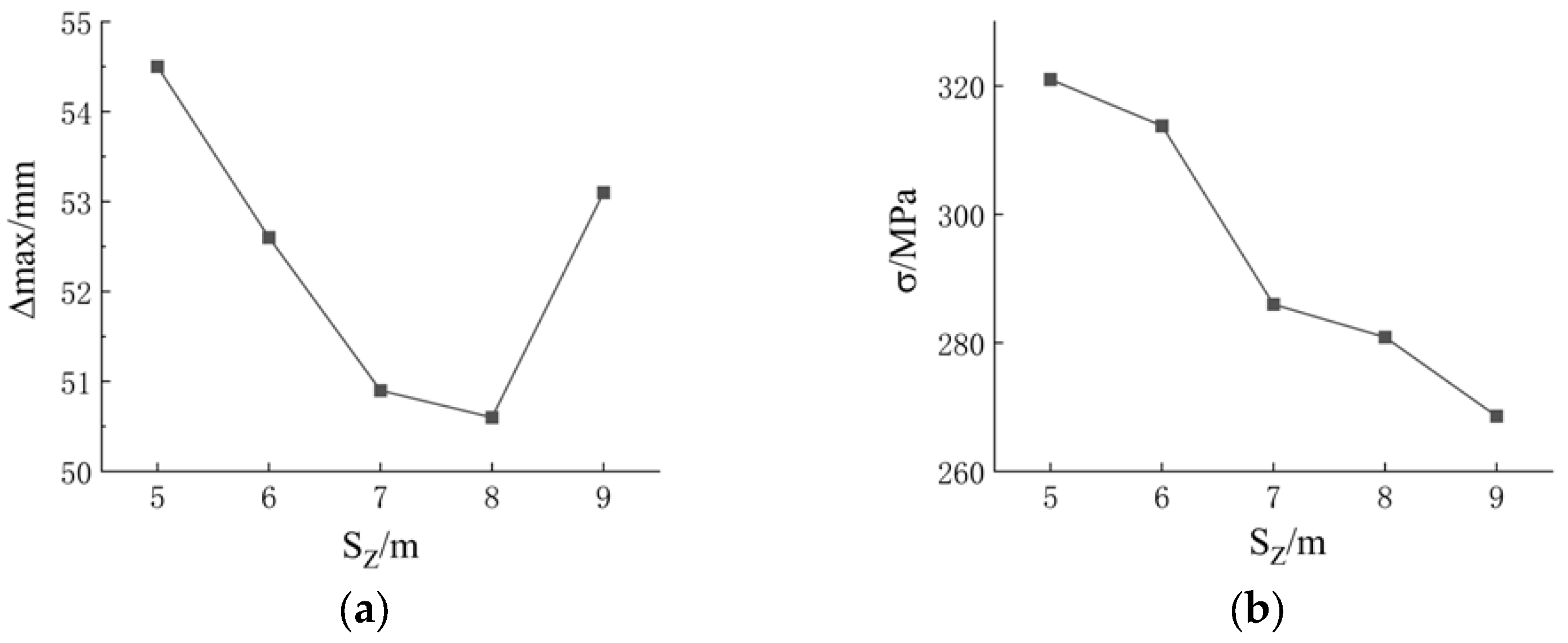
4.4. Cable Projected Length Analysis

The cable projected length SZ refers to the length of the projection of the cable along the axis of the connected rectangular crossbar in the new cable-supported reciprocal structure. A parametric analysis is conducted on the structural model with cable projected lengths ranging from 5 to 9 m to investigate the effect of different cable projected lengths on the maximum displacement and maximum stresses of the structure, with the results shown in Figure 15. All parameters, except for the cable projected length, are consistent with the model in Section 3.1.
It can be observed that the new cable-supported reciprocal structure is less sensitive to changes in the cable projected length. As the cable projected length increases, the maximum displacement of the structure initially decreases and then increases while the maximum stress of the structure decreases. This is likely due to the fact that if other parameters remain unchanged, a cable projected length that is too short results in excessive force in the strut, leading to a tendency for reverse displacement in the middle and ends of the flexural compression member. Therefore, the cable projected length of the new cable-supported reciprocal structure is chosen to be 8 m.

4.5. Pre-Tensioning Analysis

A parametric analysis is conducted on the structural model with the pre-tensioning ranging from 0 to 500 kN to investigate the effect of different pre-tensioning levels on the maximum displacement and the maximum stresses of the structure, with the results shown in Figure 16. All parameters, except for the pre-tensioning, are consistent with the model in Section 3.1.
It can be observed that the new cable-supported reciprocal structure is highly sensitive to changes in the pre-tensioning. As the pre-tensioning increases, the maximum displacement of the structure initially decreases and then increases, while the maximum stress follows a similar trend, initially decreasing and then increasing. However, when the pres-tensioning exceeds 150 kN, the structure shows reverse displacement, which increases as the pre-tensioning continues to rise. Therefore, the pre-tensioning of the new cable-supported reciprocal structure is set at 150 kN. Excessive prestress can lead to reverse displacements in reciprocal structures, and in some cases, these reverse displacements can exceed the maximum downward displacement of the structure.

5. Conclusions

A new cable-supported reciprocal structure is proposed, drawing on the construction concept of the beam string structure. This provides an innovative method for enhancing the structural stiffness of reciprocal structures. The numerical simulation analysis of stress and displacement under uniform load was carried out by applying ABAQUS to the structural model, and the results were compared with those of the general reciprocal structure. The effects of the rise/span ratio, longitudinal spacing, strut height, cable projected length, and pre-tension on the maximum displacement and maximum stress of the structure were analyzed, and the main conclusions are as follows:
(1)
The new cable-supported reciprocal structure features a simple design, ease of assembly, and efficient load distribution. It accommodates a wide variety of components, enabling the transition from small components to large spans. This structure can satisfy the requirements for both safe and rapid construction in practical projects.
(2)
The maximum stress of the new cable-supported reciprocal structure exhibits symmetry under uniform load. Under the same load, the vertical displacement of this new structure is 17% smaller than that of the general reciprocal structure, and the overall stress is also reduced. As a result, the new cable-supported reciprocal structure can effectively improve the resistance to deformation of the members.
(3)
The maximum displacement of the new cable-supported reciprocal structure decreases as the rise/span ratio increases. Under conventional loading conditions, the maximum displacements of structural models with rise/span ratios ranging from 1/8 to 1/3 all meet the code requirements. The selection of these models should be based on the specific needs of the project. Additionally, an appropriate longitudinal spacing can reduce the structural mass while still satisfying the stress and displacement requirements, but it is not recommended to exceed 6 m.
(4)
The maximum displacement of the new cable-supported reciprocal structure decreases as the strut height increases, but excessive strut height will result in an increased self-weight of the structure; it is recommended that the strut height be taken as 1/8 of the length of the basic bar. The cable projected length has a relatively small effect on the maximum displacement of the structure, but insufficient cable projected length can lead to excessive local stress; it is not recommended that the cable projected length be less than 3/5 of the length of the basic bar. Appropriate pre-tension can improve the mechanical performance of the structure.
This paper presents a design methodology for integrating strut and tension elements into reciprocal structures. The Leonardo da Vinci tessereil pont serves as the baseline model, which is further improved and analyzed through numerical simulations to validate the effectiveness of the proposed method. In future research, this methodology can be applied to the design of other types of reciprocal structures, with the inclusion of various bar cross-sections for extended research.

Author Contributions

W.D. and N.U. were responsible for the application of the proposed method. G.G. and C.W. were responsible for the planning and writing of the manuscript. H.L. was responsible for the revision of the manuscript. All authors have read and agreed to the published version of the manuscript.

Funding

This research was supported by the National Science Foundation in China (NSFC, Grant No. 52478166), the Henan University Science and Technology Innovation Team Support Program (Grant No. 22IRTSTHN019), and the Key Program of National Science Foundation of Henan Province (Grant No. 232300421133).

Data Availability Statement

Some or all data, models, or codes that support the findings of this study are available from the corresponding author upon reasonable request.

Acknowledgments

The authors would like to thank Jinchao Gu, Pengshan Tang, Hui Wang, Qichen Whang, and Yongchao Han for their valuable discussion.

Conflicts of Interest

The authors declare no conflicts of interest.

References

  1. Baverel, O.; Nooshin, H.; Kuroiwa, Y. Nexorades. Int. J. Space Struct. 2000, 15, 155–159. [Google Scholar] [CrossRef]
  2. Douthe, C.; Baverel, O. Design of nexorades or reciprocal frame systems with the dynamic relaxation method. Comput. Struct. 2009, 87, 1296–1307. [Google Scholar]
  3. Popovic Larsen, O. Reciprocal frame (RF) structures: Real and explorator. Nexus Netw. J. 2014, 16, 119–134. [Google Scholar]
  4. Song, P.; Fu, C.W.; Goswami, P. Reciprocal frame structures made easy. ACM Trans. Graph. 2013, 32, 1–13. [Google Scholar]
  5. Mesnil, R.; Douthe, C.; Baverel, O. Form finding of nexorades using the translations method. Autom. Constr. 2018, 95, 142–154. [Google Scholar]
  6. Fan, B.; Luo, C.; Xu, Y. Structural configuration analysis and detailing of wooden Rainbow bridge. Spat. Struct. 2018, 24, 91–96. (In Chinese) [Google Scholar]
  7. Asefi, M.; Bahremandi-tolou, M. Design challenges of reciprocal frame structures in architecture. J. Build. Eng. 2019, 26, 100867. [Google Scholar] [CrossRef]
  8. Widyowijatnoko, A.; Irwanuddin, I.; Aditra, R.F. Rection as a synthesis of reciprocal and tensegrity structure. Nexus Netw. J. 2019, 21, 465–478. [Google Scholar] [CrossRef]
  9. Su, Y.; Zhang, J.; Ohsaki, M. Topology optimization and shape design method for large-span tensegrity structures with reciprocal struts. Int. J. Solids Struct. 2020, 206, 9–22. [Google Scholar] [CrossRef]
  10. Piekarski, M. Floor slabs made from topologically interlocking prefabs of small size. Buildings. 2020, 10, 76. [Google Scholar]
  11. Wu, Y.; Su, Y. Experimental study and finite element analysis on mechanical behavior of suspended reciprocal grid structures. J. Build. Struct. 2021, 42, 65–75. (In Chinese) [Google Scholar]
  12. Chea, C.P.; Bai, Y.; Fang, Y. Geometric forming and mechanical performance of reciprocal frame structures assembled using fibre reinforced composites. Eng. Struct. 2022, 250, 113420. [Google Scholar] [CrossRef]
  13. Del Río-Calleja, B.; Grau Enguix, J.; García-Santos, A. Architectural systemic approach: The Serpentine Gallery 2005, a reciprocal frame case study. Buildings 2022, 12, 1051. [Google Scholar] [CrossRef]
  14. Piekarski, M. Static analysis of structural grillages made of steel reciprocal beams. Eng. Struct. 2023, 291, 116360. [Google Scholar] [CrossRef]
  15. Xia, Y.; Xiao, N.; Xu, Y. Configuration approach to reciprocal structures assembled by curved rods based on optimization algorithm. J. Build. Struct. 2024, 45, 69–75. (In Chinese) [Google Scholar]
  16. Agirbas, A. Semi-automated creation of reciprocal frame structures using deep learning. Autom. Constr. 2024, 165, 105515. [Google Scholar]
  17. Xu, P.; Zhao, P.; Liu, Y. Reciprocal frame (RF) architecture design based on statistical analysis of geometrical form parameters from built cases and parametric simulations. Constr. Build. Mater. 2024, 447, 138082. [Google Scholar]
  18. Xia, Y.; Xu, Y.; Xiao, N. Efficient calculation method for dynamic behaviour and seismic performance of reciprocal structures based on condensed nodal coding system. Soil Dyn. Earthq. Eng. 2024, 180, 108595. [Google Scholar]
  19. Martínez Arias, C.; Anaya Díaz, J. Geometric Definition of Transformable Surfaces with Homogeneous ABC Reciprocal Meshes. J. Archit. Eng. 2024, 30, 04024010. [Google Scholar]
  20. Da Vinci, L. Codex Atlanticus; Biblioteca Ambrosiana: Milano, Spain, 1989; Volume 183, pp. 69–71. [Google Scholar]
  21. Xia, Y.; Xiao, N.; Chen, H. Determination of static and kinematic determinacy of pin-jointed assemblies using rigid-body displacements as primary unknown variables. Eng. Struct. 2019, 181, 643–652. [Google Scholar] [CrossRef]
Figure 1. Rainbow bridge in Qingming shang he painting.
Buildings 15 01006 g001
Figure 2. Tessereil pont from Leonardo da Vinci’s manuscript.
Buildings 15 01006 g002
Figure 3. Solid configuration of the new cable-supported reciprocal structure.
Buildings 15 01006 g003
Figure 4. Basic element of cable-supported triangular rod reciprocal structure: (a) basic element; (b) left and right types.
Buildings 15 01006 g004
Figure 5. Overall model parameters.
Buildings 15 01006 g005
Figure 6. Basic design flow.
Buildings 15 01006 g006
Figure 7. Finite element analysis model.
Buildings 15 01006 g007
Figure 8. Q355 steel constitutive relationship model.
Buildings 15 01006 g008
Figure 9. Displacement nephograms: (a) general reciprocal structure; (b) new cable-supported reciprocal structure.
Buildings 15 01006 g009
Figure 10. Stress nephograms: (a) general reciprocal structure; (b) new cable-supported reciprocal structure.
Buildings 15 01006 g010
Figure 11. Load–displacement curves of two structures.
Buildings 15 01006 g011
Figure 12. Influence of rise/span ratio: (a) maximum displacement; (b) maximum stress.
Buildings 15 01006 g012
Figure 13. Influence of longitudinal spacing: (a) maximum displacement; (b) maximum stress.
Buildings 15 01006 g013
Figure 14. Influence of strut height: (a) maximum displacement; (b) maximum stress.
Buildings 15 01006 g014
Figure 15. Influence of cable projected length: (a) maximum displacement; (b) maximum stress.
Buildings 15 01006 g015
Figure 16. Influence of pre-tensioning: (a) maximum displacement; (b) maximum stress.
Buildings 15 01006 g016
Table 1. Cross-sectional dimension and mass of two structures.
TypeThe General Reciprocal StructureThe New Cable-Supported Reciprocal Structure
Cross-sectional dimension (mm)Mass (t)Cross-sectional dimension (mm)Mass (t)
The rectangular crossbar150 × 200 × 8 mm12.67 t150 × 200 × 6 mm9.61 t
The circular bar 150 × 8 mm3.58 t 150 × 6 mm2.72 t
The circular strut 0 150 × 6 mm0.81 t
The cable 0 30 mm1.40 t
The short bar 50 mm0 50 mm0
Total16.25 t14.54 t
Table 2. Mass and mechanical performance indices of two structures.
Structure TypeMass (t)Maximum Displacement (mm)Maximum Stress (MPa)Maximum Bearing Capacity (kN·m−2)
The general reciprocal structure16.25 t56.0 mm334 MPa4.02 kN·m−2
The new cable-supported reciprocal structure14.54 t46.3 mm298 MPa4.56 kN·m−2
Improvement rate (%)12%17%11%13%
Disclaimer/Publisher’s Note: The statements, opinions and data contained in all publications are solely those of the individual author(s) and contributor(s) and not of MDPI and/or the editor(s). MDPI and/or the editor(s) disclaim responsibility for any injury to people or property resulting from any ideas, methods, instructions or products referred to in the content.

