1. Introduction
Due to the inherent brittleness and susceptibility to cracking of conventional concrete materials, concrete structures are often prone to issues such as cracking, spalling, carbonation, and reinforcement corrosion when exposed to earthquakes, fire, and harsh environmental conditions like freeze–thaw cycles and high salt concentrations during their service life. However, Fiber Reinforced Cementitious Composite (FRCC), also known as Engineered Cementitious Composite (ECC) [
1], Ultrahigh Performance Fiber Reinforced Cementitious Composite (UHPFRCC) [
2], Ultrahigh Toughness Cementitious Composite (UHTCC) [
3], High Ductile Concrete (HDC) [
4], Textile Reinforced Concrete (TRC) [
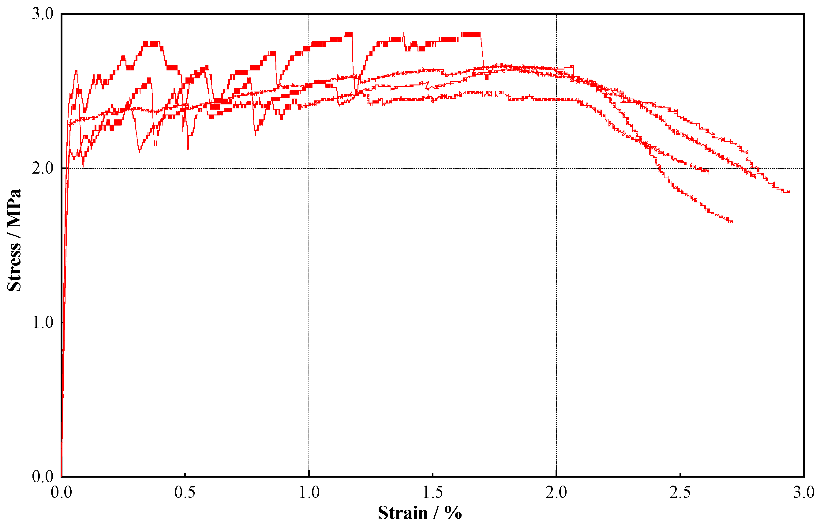
5], etc., offers a solution with its unique properties of strain hardening and multiple-seam cracking. The material exhibits an ultimate tensile strain exceeding 3%, effectively limiting crack widths to less than 0.1 mm even under ultimate tensile conditions [
1], and demonstrates a high-temperature degradation threshold, withstanding up to 1 h of exposure at 200 °C [
6]. These mechanical properties play a crucial role in improving the durability of reinforced concrete (RC) structures or composite structures, as well as in their effective application in strengthening and/or retrofitting [
3,
4,
5,
7].
Based on the mechanical properties and durability of FRCC mentioned above, it is frequently employed for structural reinforcement purposes [
8,
9,
10]. Qudah et al. [
11] and Zhang et al. [
12] conducted experimental studies on the seismic performance of beam–column joints strengthened with ECC. The findings revealed that ECC can considerably enhance the energy dissipation capacity of the joints when subjected to low circumferential reciprocating loads. Moreover, the axial compression ratio was identified as the primary factor influencing the ductility of the joints. Tian et al. [
13] aim to comprehensively examine the flexural synergistic effect of RC beams strengthened with ECC through experimental studies. Additionally, a bond-slip model of the ECC and concrete interface is employed in finite element analysis to simulate and validate the failure mode, load-deflection response, and strain distribution at the mid-span cross-section. Zheng et al. [
14] conducted flexural performance tests on nine damaged concrete beams, which were strengthened and repaired using HDC layers of varying thicknesses. The test results demonstrated a shift in the damage mode of the beams from brittle to ductile, accompanied by significant improvements in load-carrying capacity, energy dissipation capacity, and ductility. Wang and Wan et al. [
15,
16] revealed the effects of different mortar matrix strengths and textile ratios on the seismic performance of columns and walls, such as bearing capacity and ductility, employing experimental and theoretical modeling studies of columns and walls strengthened with thin-layer TRC. The aforementioned studies have confirmed that FRCC is suitable for seismic reinforcement in RC beams and columns. Further investigation is needed to understand the impact of high-dosage fibers on the compatibility of FRCC in large-area, thin-layer reinforcement applications, as well as its mechanical properties under unvibrated densification conditions.
In addition, traditional crack assessment methods primarily rely on visual inspection or the localized attachment of strain gauges for measurement. These approaches are inherently limited by the small amount of data they can provide and are often hindered by issues such as high subjectivity and significant data discreteness. Sutton et al. [
17] were the first to apply the Digital Image Correlation (DIC) technique to damage assessment, demonstrating its capability to accurately capture the processes of crack initiation and propagation. Gencturk et al. [
18] utilized the non-contact measurement capabilities of DIC to conduct full-field testing of the stress distribution in concrete members. Their findings revealed that load paths could be identified even at very small strain levels, well below the cracking strain of concrete (approximately 0.00008). Lacidogna et al. [
19] further applied the DIC technique to analyze crack formation and propagation in pre-notched concrete beam specimens under three-point bending. They evaluated the correlation between the principal strain directions obtained from DIC and the observed crack paths. Recent studies [
20,
21] have similarly demonstrated that the DIC technique, when combined with the cracking characteristics of cementitious materials, can establish a quantitative relationship between crack patterns and material properties. This provides a promising new approach for evaluating the effectiveness of structural reinforcement in future applications.
Spraying-type FRCC is a type of high-mobility FRCC that adjusts the rheology of traditional casting-type FRCC. This adjustment allows it to maintain its original high toughness while also meeting the low cohesion requirements of the pumping process. Additionally, it ensures high cohesion with the base layer of the sprayed surface concrete. Currently, researchers both domestically and internationally have made notable progress in the research and application of sprayed FRCC [
22,
23,
24,
25,
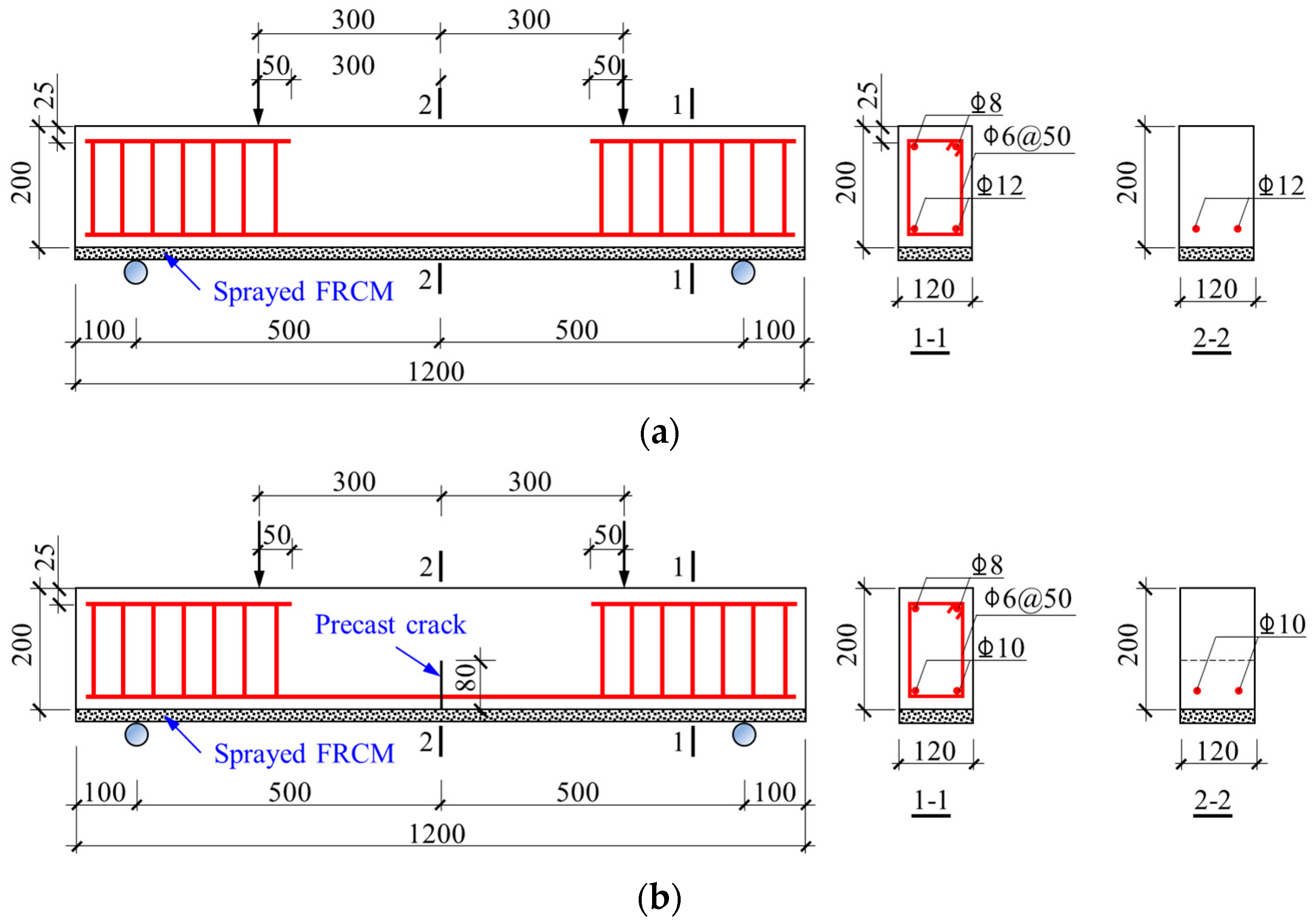
26]. However, further investigation into the mechanical properties of RC structures reinforced with sprayed FRCC is necessary. This paper aims to deepen the understanding by conducting flexural performance tests on reinforced concrete beams with and without cracks. Different thicknesses of sprayed FRCC are used for reinforcement, and a comparative analysis is carried out. The study focuses on examining the mechanical mechanism and reinforcement effect of reinforced concrete beams reinforced with varying thicknesses of sprayed FRCC.
3. Test Results and Analysis
This section evaluates the accuracy of the DIC-based crack identification technique through comparative analysis with visual observations and crack patterns at critical loading stages. Additionally, the effects of sprayed FRCC thin layer thickness and reinforcement ratios on crack propagation mechanisms and failure modes are investigated. The analysis further extends to load-deflection data acquired at these stages, enabling quantitative assessment of how different reinforcement configurations influence the specimen’s structural performance, particularly in terms of load-bearing capacity evolution and deflection behavior characteristics.
3.1. Comprehensive Characterization of Damage Across Various Loading Stages
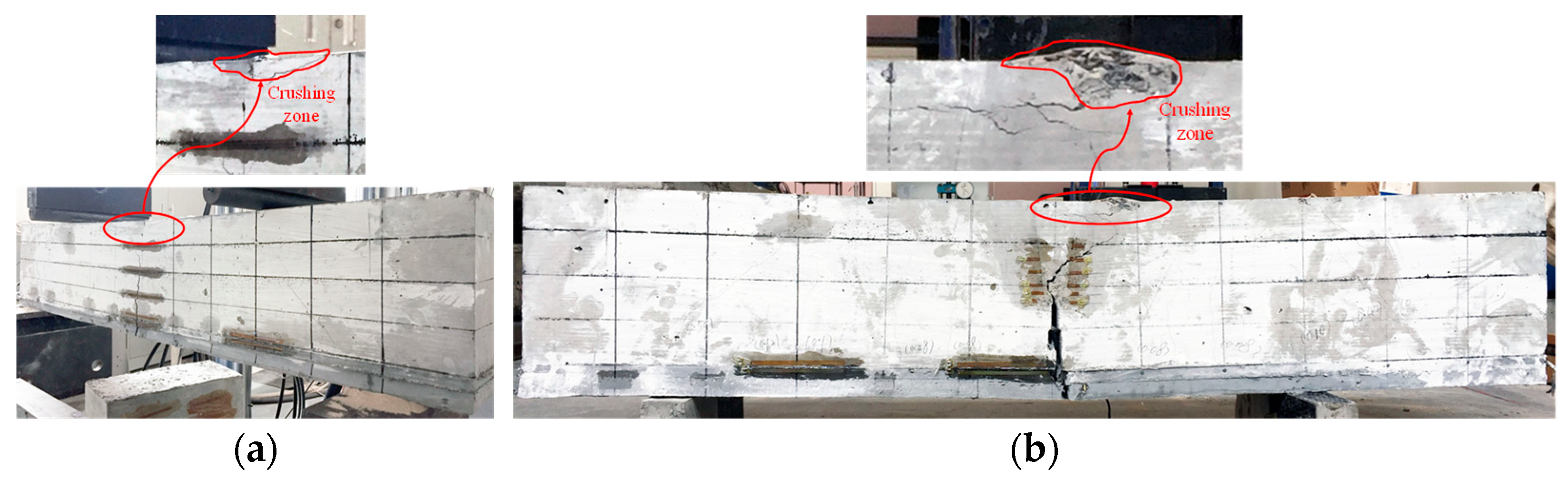
Figure 5 showcases the final test damage photos of the beams, namely RCC-S30 and RC-S30, both with and without precast cracks, after being strengthened with a 30 mm sprayed FRCC thin layer. The crack development images of the RC series and RCC series beams at the final damage stage are shown in
Figure 6 and
Figure 7, respectively. Furthermore,
Figure 6 and
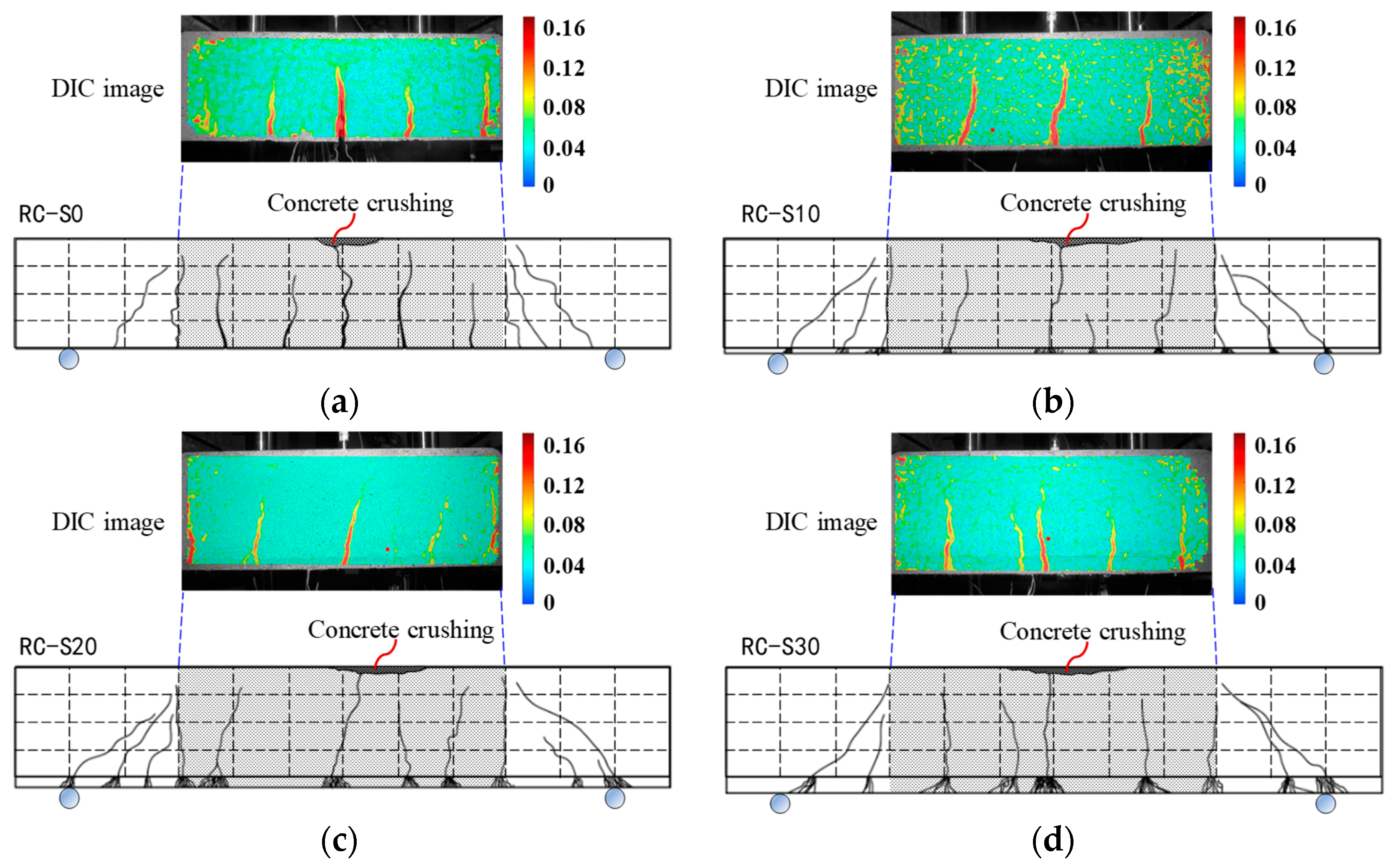
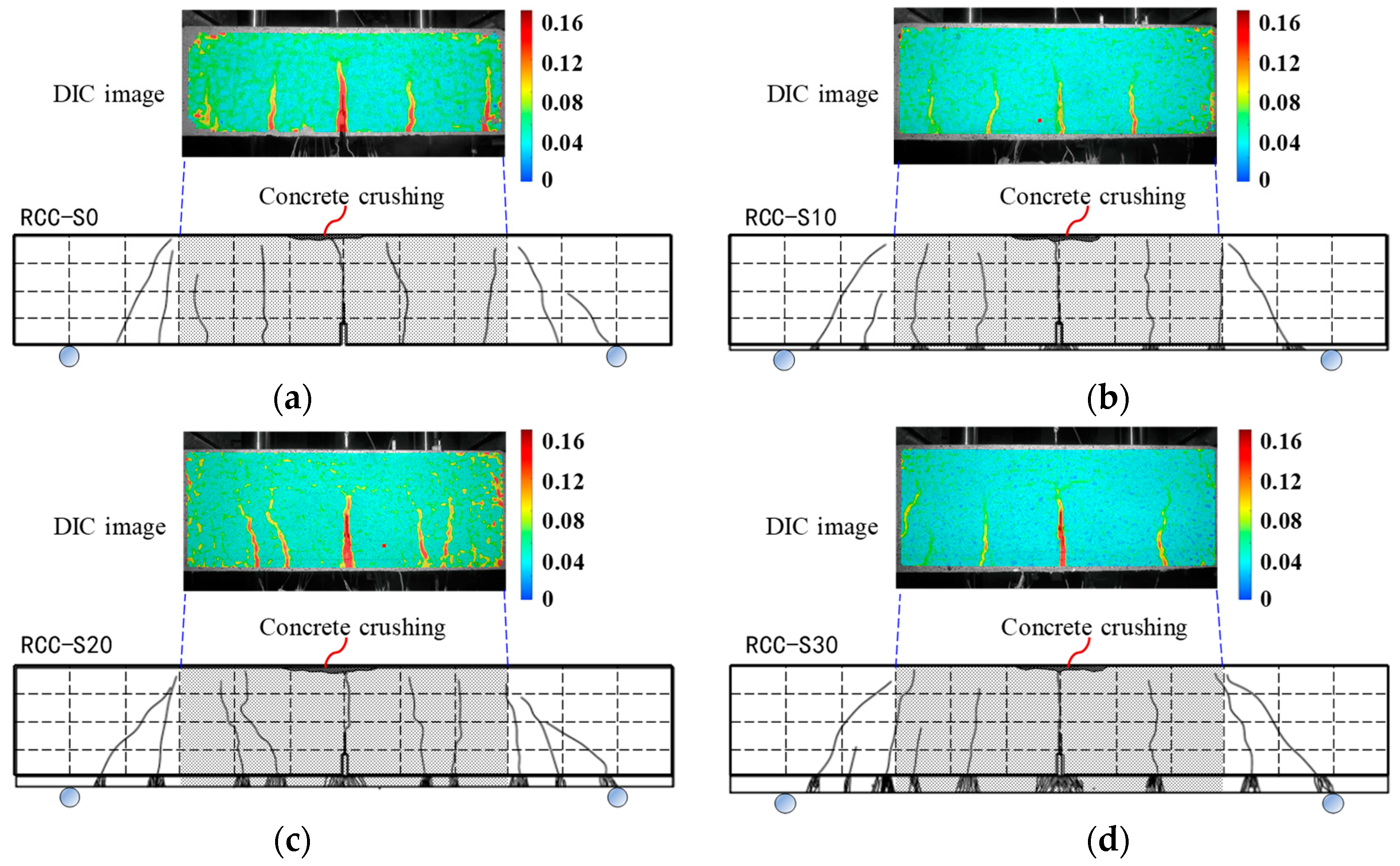
Figure 7 present the DIC crack morphology images of the purely curved section portion of the mid-span during the loading process. In the DIC images, the red region indicates a higher strain, with the strain values decreasing in magnitude from red to yellow, green, and finally blue.
From these figures, it is evident that the unreinforced RC and RCC beams experience a complete extension of each crack under the applied bending load. In contrast, the beams reinforced with sprayed FRCC demonstrate effective control over the extension of cracks, except for the main crack. This can be attributed to the reinforcing layer’s ability to effectively control crack propagation. However, this control also results in a certain reduction in the deflection of the reinforced beams. Next, we will provide a separate description of the damage observed in different series of beams.
3.1.1. RC Series Specimens
Figure 6 shows the bending damage mode and crack development pattern of the RC series beams. From
Figure 6, it can be seen that the final damage patterns of all four groups of specimens are concrete crushing in the upper compression zone of the beams, a number of cracks extend to both sides of the support, the length and width of the cracks are fully developed, and the tensile longitudinal tendons yield.
For the unstrengthened RC beams, the behavior observed in
Figure 6a can be attributed to the quasi-brittle nature of concrete. Initially, as the load increased to 28.1 kN, a small crack became visible in the mid-span region. As the loading continued, this crack gradually extended towards the top of the beam, and its width increased to more than 0.15 mm, forming the main crack. Simultaneously, new cracks started to develop on both sides of the main crack, maintaining a relatively consistent spacing towards the support. These cracks exhibited a similar progression to the main crack. As the number of concrete cracks increased and their morphology developed, the tensile stresses experienced by the concrete at these cracks were gradually transferred to the reinforcing bars. This transfer of stress continued until the longitudinal reinforcing bars yielded in tension. Eventually, the concrete at the top of the beam in mid-span became crushed and damaged due to the increased load and stress concentration.
For the RC series, beams strengthened with different thicknesses of FRCC thin layers sprayed at the bottom of the beams (
Figure 6b–d) resulted in an increase in moment of inertia with the height of the beam after reinforcement. This increase led to a significant improvement in the initial cracking strength, with the unreinforced specimen RC-S0 having a cracking strength of 28.1 kN compared to 69.1 kN for the reinforced specimen RC-S30, representing a 145.9% increase.
During the four-point bending test, the stress and strain values at the bottom of the beam at the mid-span were the largest. As a result, tiny vertical cracks initially appeared in the mid-span region of the FRCC layer. The strain-hardening characteristics of FRCC played a crucial role in preventing the rapid expansion of these cracks into major cracks. Instead, multiple tiny cracks formed near the initial cracks, effectively controlling the premature appearance of cracks at the bottom of the original RC beams. This behavior provided a certain amount of tensile stress, which helped delay the yielding of the specimens.
As the loads and deflections increased, fine cracks started to develop in various locations within the FRCC layer and gradually extended towards the bottom of the original RC beam. Once the cracks penetrated through the FRCC layer and reached the plain concrete at the bottom of the RC beam, the cracked region of the FRCC layer in the mid-span no longer experienced tensile stress, resulting in a small unloading phenomenon. Consequently, the tensile stresses were then transferred to the corresponding main reinforcing bars to bear the load.
As the loading progressed, the number and width of cracks in the concrete increased. This happened as the FRCC layer gradually withdrew from its stressed working condition. Eventually, the tensile reinforcing bars yielded, and the concrete at the top surface of the mid-span RC beam was crushed under the applied load.
The test results indicate that thicker sprayed FRCC reinforcement layers result in higher flexural stiffness, higher initial cracking loads, and delayed crack penetration through the FRCC layer. However, it is important to note that the ultimate damage is still primarily controlled by the tensile yielding of the reinforcing bars and the crushing of the concrete. Therefore, whether or not the FRCC layer is applied to strengthen the RC beams has little effect on the ultimate load carrying capacity.
3.1.2. RCC Series Specimens
Referring to
Figure 7, the bending damage mode and crack propagation of RCC series beams are similar to those of RC series beams. The ultimate damage mode of both types of beams is characterized by the crushing of concrete in the compression zone, while the longitudinal reinforcing bars undergo yielding due to tensile stress.
In the case of unstrengthened RCC beams, as shown in
Figure 7a, the initial crack typically occurred at the tip of the precast crack. This is because the height of the precast crack in the mid-span reached 40% of the beam height. During the initial loading stage, the presence of the precast crack reduced the moment of inertia. As a result, all the tensile stresses at the bottom of the beam were carried by the longitudinal reinforcing bars, leading to a significantly larger deflection in the mid-span. At a loading of 37.3 kN, the deflection reached 0.41 mm, and the neutral axis of the cross-section was located close to the tip of the precast crack. At this stage, a small but visible crack emerged. As the loading progressed, the mid-span crack gradually extended towards the top, with its width gradually expanding to more than 0.15 mm, eventually forming the main crack. The appearance, development, and damage characteristics of other cracks in the beam were essentially similar to those observed in unstrengthened RC beams. However, due to the simulated corrosion and smaller diameter of the reinforcing bars in the RCC beam, its yield load and ultimate load were lower than those of the RC beam. Despite this, the deflections at the point of damage were generally comparable between the two types of beams.
In the case of RCC series beams strengthened with different thicknesses of FRCC layers sprayed at the bottom of the beams (
Figure 7b–d), the good bond between the FRCC layer and the concrete, as well as the strain-hardening material properties of FRCC itself, plays a significant role in transmitting tensile stresses. This reduced the weakening of the beam section caused by the precast crack and improved the bending cross-section moments, resulting in a significant increase in the initial cracking strength. For example, the specimen RCC-S30 showed an initial cracking strength of 58.6 kN, which was 57.1% higher than the specimen RCC-S0, and the deflection at initial cracking decreased by 46.3%.
During the loading process, the multi-slit cracking characteristics and load-holding effect of the FRCC-reinforced layer delayed the degradation of flexural stiffness and the yielding of the beams. Although multiple flexural cracks gradually appeared on both sides of the precast cracks in the RCC beams, they were not immediately reflected in the FRCC layer. As the load and deflection increased, multiple fine cracks formed in the FRCC layer corresponding to the beam cracks and gradually penetrated. When the cracks penetrated through the FRCC layer, the cracked region of the FRCC layer corresponding to the precast cracks no longer bore tensile stress, resulting in a small unloading phenomenon. The tensile stresses were then transferred to the corresponding main reinforcing bars to bear. As the loading continued, the number and width of cracks in the concrete in the beams increased until the tensile reinforcing bars yielded and the concrete at the top surface of the RCC beam span was crushed due to the slow withdrawal of work at different cracks in the FRCC layer. Similar to RC series beams, the thicker the sprayed FRCC reinforcement layer and the higher the initial cracking load, the later the cracks penetrate through the FRCC layer. The final damage was controlled by the yielding of reinforcing bars in tension and the crushing of compressed concrete. Therefore, the application of FRCC for reinforcement in the tensile zone of the beams has little effect on the yield capacity and ultimate capacity of the beams.
3.2. DIC and Visual Analyses
The comparison between the actual crack figures in
Figure 6 and
Figure 7 and the DIC strain cloud figures showed that the high-strain regions identified by DIC generally align with the locations of larger actual cracks and their development regions. However, discrepancies exist in the identification of fine cracks and the extended lengths of some cracks. Additionally, the strain gradient changes in the DIC figures can indirectly reflect crack width, with the maximum width reaching 0.16 mm, which closely matches the actual measured maximum crack width.
When comparing the crack extension paths in the DIC cloud figures with the actual crack patterns, similarities are observed in crack direction and branch crack distribution. However, differences remain in the number of cracks and their extension angles, likely due to the accuracy limitations of the DIC crack identification process. The strain-concentrated areas in the DIC figures correspond to the tensile zones or stress-concentrated regions of the beams, which coincide with the observed crack initiation locations. This suggests that the primary cause of crack initiation is the tensile stress in the concrete exceeding its tensile strength. The strain gradient changes in the DIC maps also reflect the redistribution of stresses during crack propagation. The crack extension paths typically follow the stress concentration regions, consistent with the crack development trends observed in the actual crack photographs. However, the resolution and accuracy of the DIC figures may be influenced by test conditions, such as lighting and surface scattering quality, leading to potential errors in identifying crack locations or widths.
Overall, the comparative analysis of the DIC strain cloud figures and actual crack photographs verify the accuracy and reliability of the DIC technique in identifying cracks.
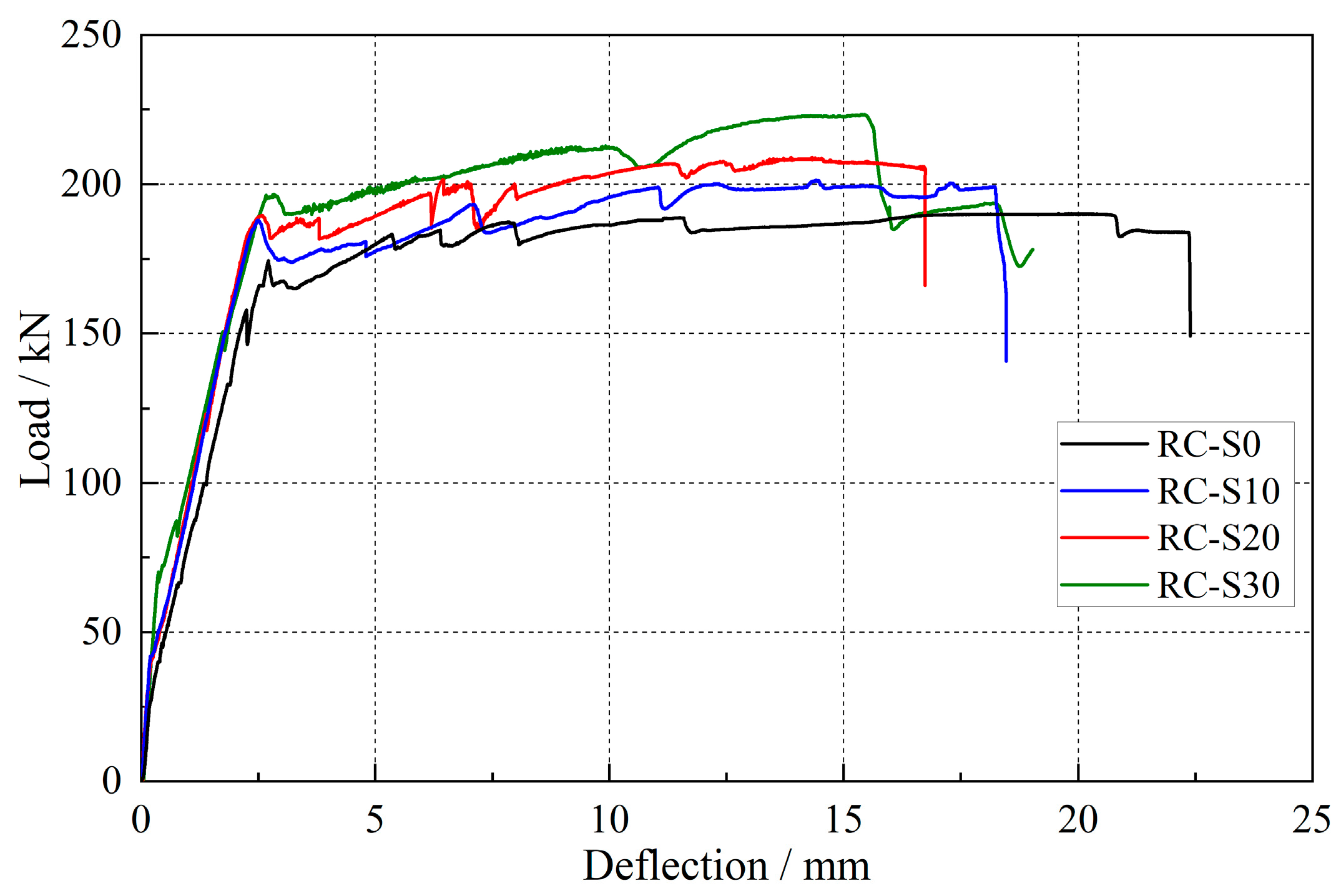
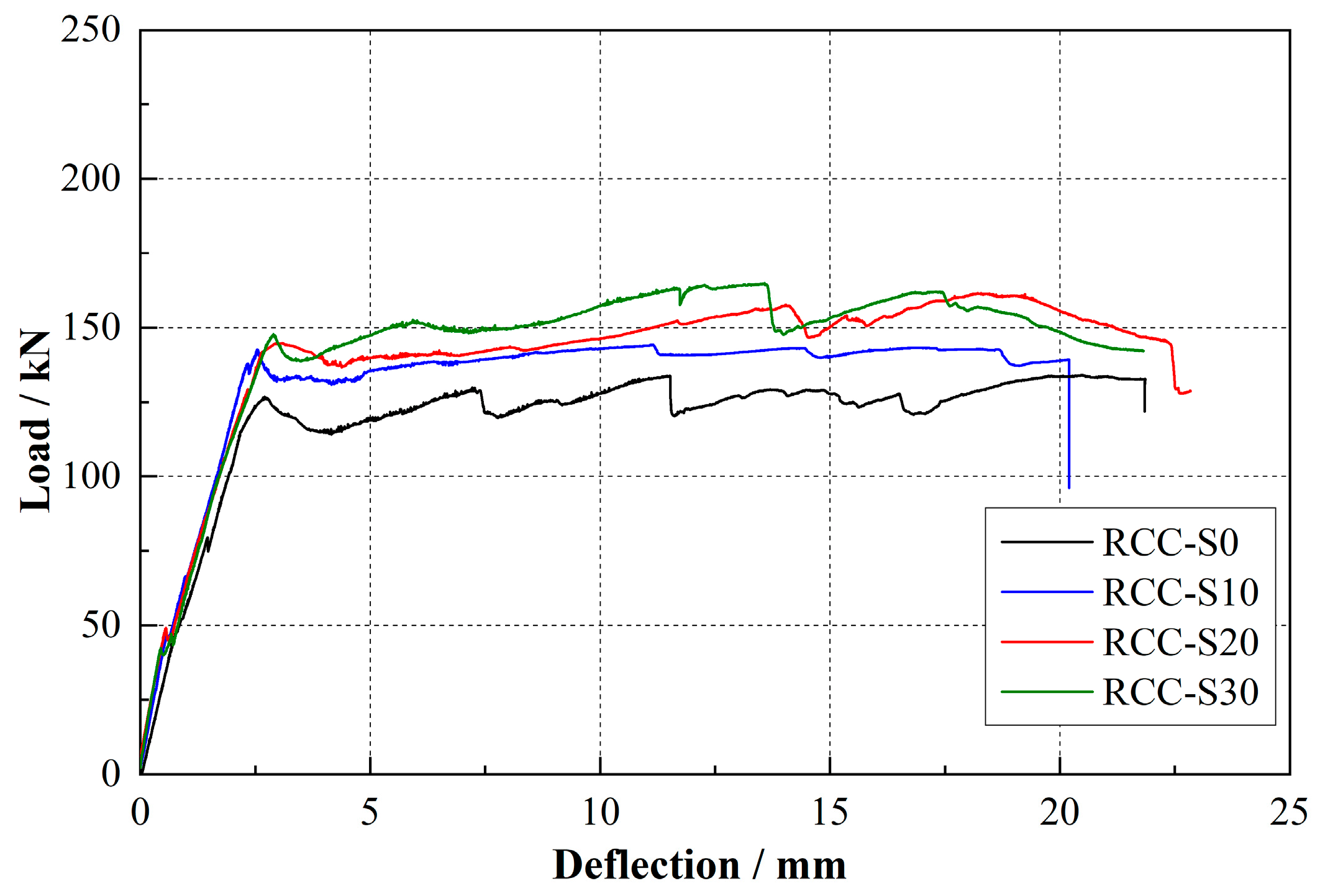
3.3. Load-Deflection Relation
The load-deflection curves for the RC and RCC series of beams are illustrated in
Figure 8 and
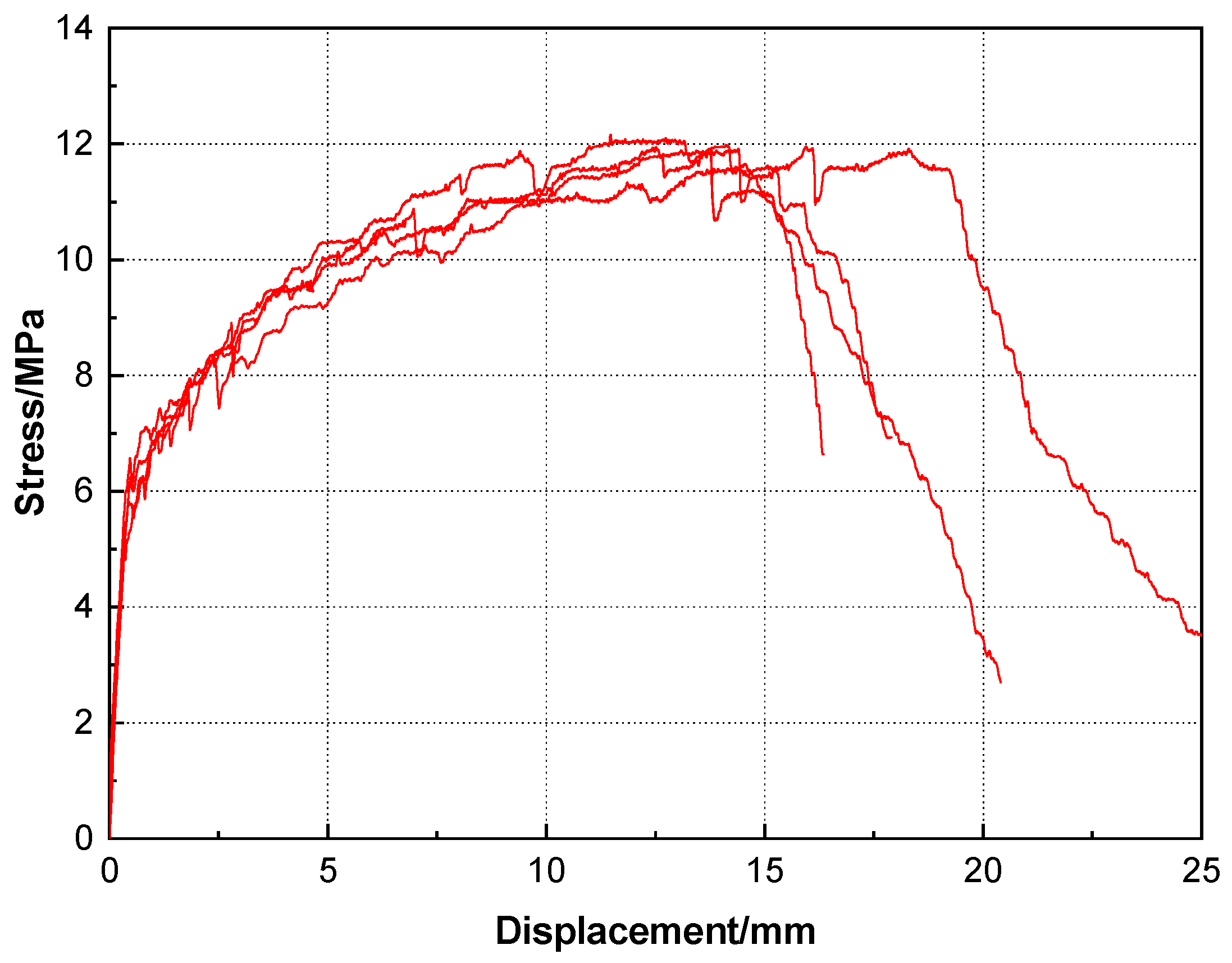
Figure 9, showing the behavior at mid-span. These curves can be divided into three distinct stages: the elastic stage before yielding, the strain hardening stage following yielding, and the destructive stage after reaching the peak load. In the elastic stage, the displacement is linearly related to the load, meaning that the beam’s stiffness increases with the thickness of the FRCC layer. Initial cracking occurs during this stage but has minimal impact on overall stiffness, although a noticeable jitter point can be observed on the curve. As the load increases, the longitudinal reinforcement strain of the beam reaches the yield strain, and the beam enters the strain intensification stage. During this stage, the load–displacement curve exhibits a gentle upward curve, indicating a small slope but rapid mid-span deflection growth. Additionally, multiple cracks begin to appear in the cross-section of the beam and fine cracks emerge in the FRCC layer, while overall stability is maintained. As the mid-span deflection reaches a certain point and the load–displacement curve peaks, the beam enters the damage stage. At this point, the beam is unable to withstand the external load, the main crack in the span opens up, and the concrete in the upper compression zone crashes, resulting in a steep decrease in the load–displacement curve. The corresponding peak load at this point represents the ultimate load of the beam.
Table 6 lists the load values and their corresponding mid-span displacements for the different loading stages mentioned above.
Analysis of the data from
Figure 8 and
Figure 9 and
Table 6 reveals that the load values and stiffness of the sprayed FRCC reinforced RC and RCC series beams surpass those of the unreinforced beams at all stages of the process. Additionally, the mid-span deflections corresponding to the initiation and yielding loads increase with the thickness of the reinforcement layer, while the mid-span deflections corresponding to the ultimate load decrease with the thickness of the reinforcement layer. This observation suggests that as the thickness of the reinforcing layer increases, the sprayed FRCC effectively controls crack extension after yielding of the beams, whether precast cracks are present or not, and also bears a portion of the tensile force.
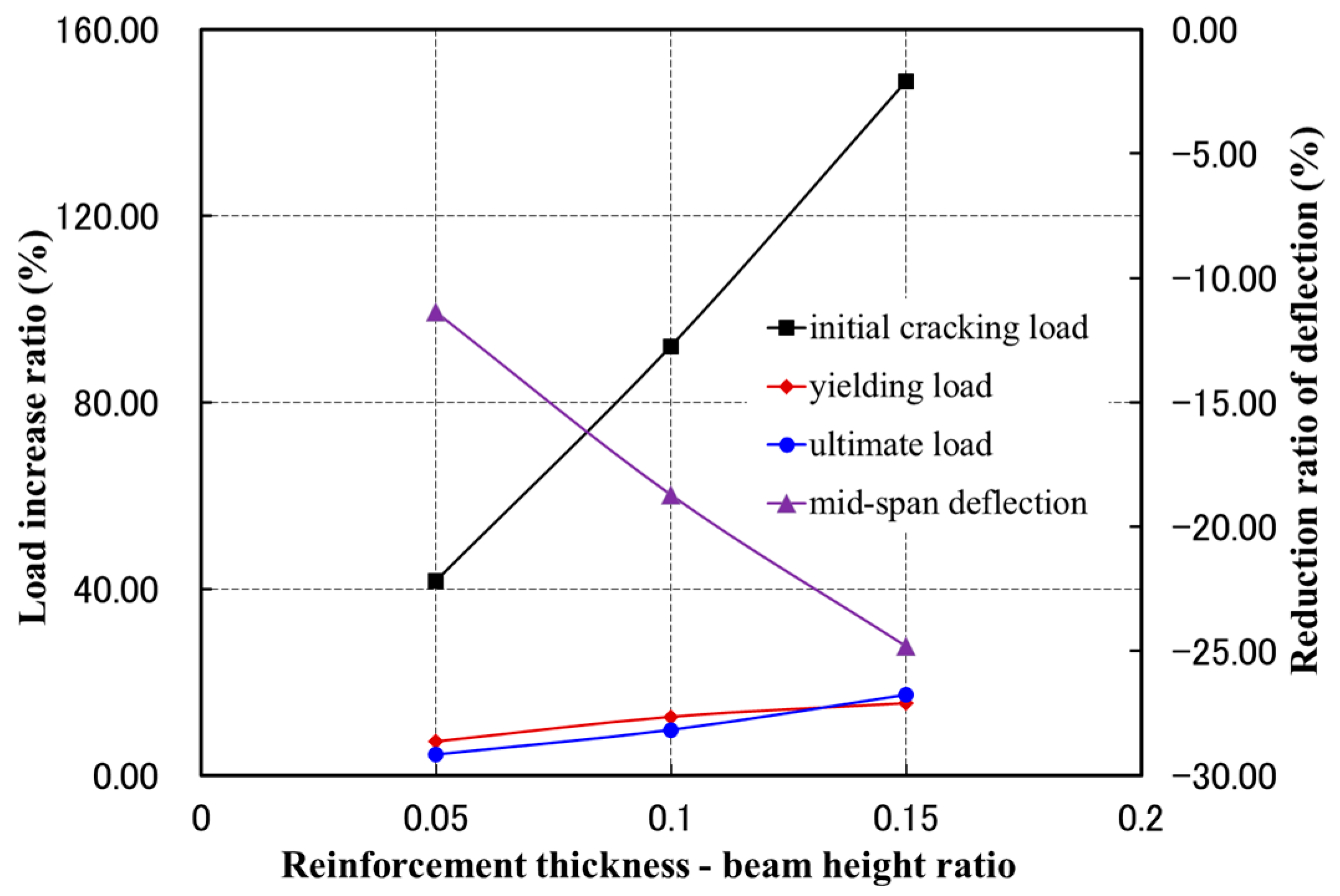
The thickness-to-height ratio of the sprayed FRCC reinforcement was used as a dimensionless variable to analyze its effect on the load-carrying capacity and mid-span deflection of RC beams. As shown in
Figure 10, the initial cracking load, yield load, and ultimate load of the strengthened RC beams increased almost linearly with the rise in the thickness-to-height ratio. Conversely, the mid-span deflection at the ultimate load decreased nearly linearly with the increase in this ratio. Specifically, the mid-span deflections of RC-S10, RC-S20, and RC-S30 at ultimate load were reduced by 11.4%, 18.7%, and 24.8%, respectively, compared to unreinforced RC beams, as listed in
Table 6.
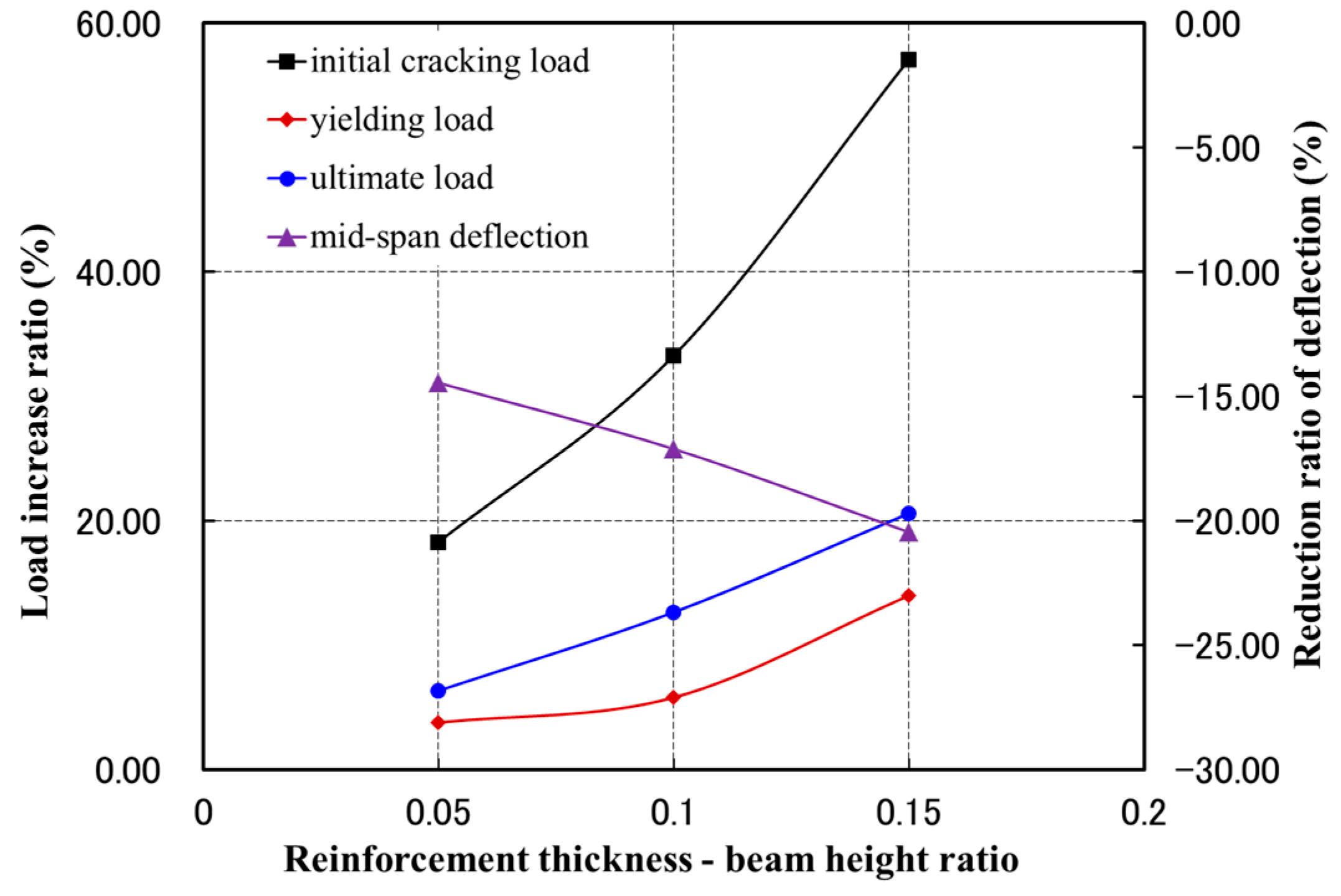
For the RCC series, as shown in
Figure 11, the relationship between the initial cracking load enhancement rate and the ratio of sprayed FRCC thickness to beam height follows a quadratic polynomial trend within a certain range of reinforcement thickness. In contrast, the yield and ultimate loads show an approximately linear positive correlation with this ratio, while the mid-span displacement exhibits a parabolic decreasing trend. This behavior indicates that, for beams with prefabricated cracks under bending, stress concentration occurs at the cracked cross-section. At the initial cracking stage, the reinforcement stress remains minimal, and the sprayed FRCC layer effectively transfers stress across the cracked section, significantly reducing the stress concentration. As the thickness of the sprayed FRCC layer increases, this stress concentration reduction becomes more pronounced, delaying crack propagation at the crack tip. This combined effect enhances the initial cracking load, resulting in a slightly nonlinear increase in its enhancement rate.
For yield and ultimate loads, the relationship remains linear, as the reinforcement primarily transmits bending and tensile stresses at these stages, reducing the superposition effect of the FRCC layer. As shown in
Table 6, the bearing capacity of the reinforced specimens improved significantly. For the RCC-S30 specimen, reinforced with a 30 mm thick sprayed FRCC layer, the yield and ultimate bearing capacities increased by 13.9% and 20.6%, respectively, compared to the unreinforced RCC-S0 specimen. Additionally, these values were restored to 85.5% and 85.1% of the uncracked and uncorroded RC-S0 specimen, demonstrating that the sprayed FRCC provides an effective repair solution.
4. Conclusions
The mechanical performance tests conducted on RC beams with or without precast cracks, strengthened by sprayed FRCC thin layers, along with DIC-based crack observation studies, led to the following conclusions:
- (1)
The flexural initial crack load, yield load, and ultimate load of RC beams with/without precast cracks strengthened by thin layers of sprayed FRCC increased with the ratio of the thickness of the FRCC layer to the original beam height and were essentially linear;
- (2)
After spraying a 30 mm thick FRCC thin layer, the yield load and ultimate load of RC beams with precast cracks can be increased to more than 70% of the corresponding load of the specimens without precast cracks. The good toughness is maintained well, which verifies the good repair effect of spraying FRCC on RC beams with or without damage.
- (3)
The local cracking strain is usually transferred to the sprayed FRCC thin layer in the normal service stage of RC beams with cracks. This transfer of strain results in the formation of finely distributed microcracks within the thin layer of FRCC, typically less than 0.1 mm in width. These microcracks are formed due to the strain-hardening property of FRCC and the bridging effect of fibers. These microcracks effectively limit the further expansion of cracks, thereby enhancing the flexural and shear performance of RC beams. Additionally, this phenomenon has significant benefits for the durability of RC structures, as it helps resist infiltration, chloride-ion attack, and carbonation.
- (4)
DIC-based crack observation offers the ability to visualize the distribution, width, and development of cracks. This technique provides valuable digital images that can be used to verify the effectiveness of FRCC in enhancing ductile reinforcement.
The findings of this study demonstrate that FRCC materials can be effectively utilized for structural reinforcement through spray application. This method not only eliminates the need for formwork required in conventional reinforcement techniques but also significantly reduces the reinforcement duration. While the application of thin sprayed layers of FRCC has a relatively limited impact on enhancing load-carrying capacity, it proves highly effective in controlling crack propagation and preventing the intrusion of harmful ions, thereby serving as a durability-focused reinforcement solution. However, due to the limited number of tests conducted in this study, further research is necessary to validate its applicability across various structural components and durability scenarios. Nonetheless, the sprayed FRCC thin-layer method holds great promise as an innovative approach to improving performance and extending the service life of RC structures.


