1. Introduction
Many researchers have reported as early as the nineteen-eighties and -nineties that one of the usual causes of earthquake losses is the so-called seismic interaction, i.e., the collisions that take place between adjacent buildings which are in contact or separated by an inadequate seismic joint [
1,
2,
3,
4,
5,
6]. The phenomenon, which is also referred to in the literature as seismic pounding, arises due to out-of-phase vibration of the interacting structures and is more pronounced when their dynamic characteristics are essentially different. For example, seismic interaction is particularly intense in cases where the adjacent structures have different heights, belong to different structural types (frame, wall, dual systems), or are made of different materials (reinforced concrete, masonry, steel, etc.). With regard to the relative location of the adjoining buildings, the seismic interaction is categorized as being symmetric or asymmetric (
Figure 1). The fundamental difference between these two kinds of interaction is that the asymmetric one induces additional torsional oscillations of the floors. Moreover, with regard to the relative storey levels of the buildings, the seismic pounding is characterized either as floor-to-floor (type A) or as floor-to-column (type B). In the former, the collisions take place between the slabs, while in the latter, the slabs of one building strike the external columns of the other within their clear height (
Figure 2).
Seismic pounding was the objective of much research during the few last decades. Initially, the phenomenon was studied with the aid of simplified single- and multi-degree-of-freedom systems [
7,
8,
9,
10]. These fundamental publications revealed the key parameters decisively affecting the response, like the dynamic characteristics of the models, the separation gap width, and, in case of multiple systems in a row, the exact location of each model. Thereafter, both A and B types of symmetric seismic pounding were thoroughly investigated [
11,
12,
13,
14,
15,
16]. In the authors’ opinion, the most important derivation of these investigations is that seismic pounding may cause critical shear situations of the columns. In particular, for pounding type A, the columns of the storey located immediately over the higher contact point are more vulnerable. For pounding type B, the external columns that directly suffer the impact experience excessive shear forces. Furthermore, the asymmetric seismic interaction was studied in detail and it was demonstrated that the torsional vibrations induced may significantly amplify the overall structural response [
17,
18,
19,
20,
21,
22,
23,
24]. In addition, many researchers focused on certain special issues related to seismic pounding, such as the determination of the minimum required gap size to prevent collisions [
25,
26,
27,
28,
29,
30,
31,
32], the effect of soil–structure interaction [
33,
34,
35,
36,
37], the pounding between isolated buildings [
38,
39,
40], and bridges [
41,
42]. Finally, potential measures in order to mitigate the consequences of the phenomenon were proposed. Such measures include the construction of properly placed shear walls [
43,
44] and the utilization of various types of dampers [
45,
46,
47] and composite materials [
48].
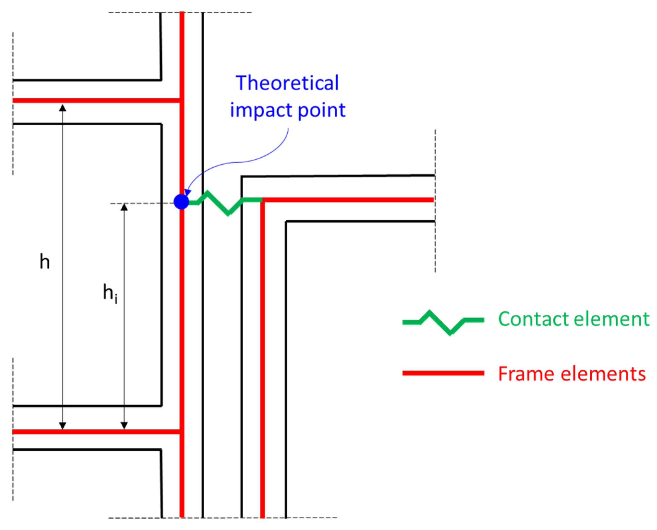
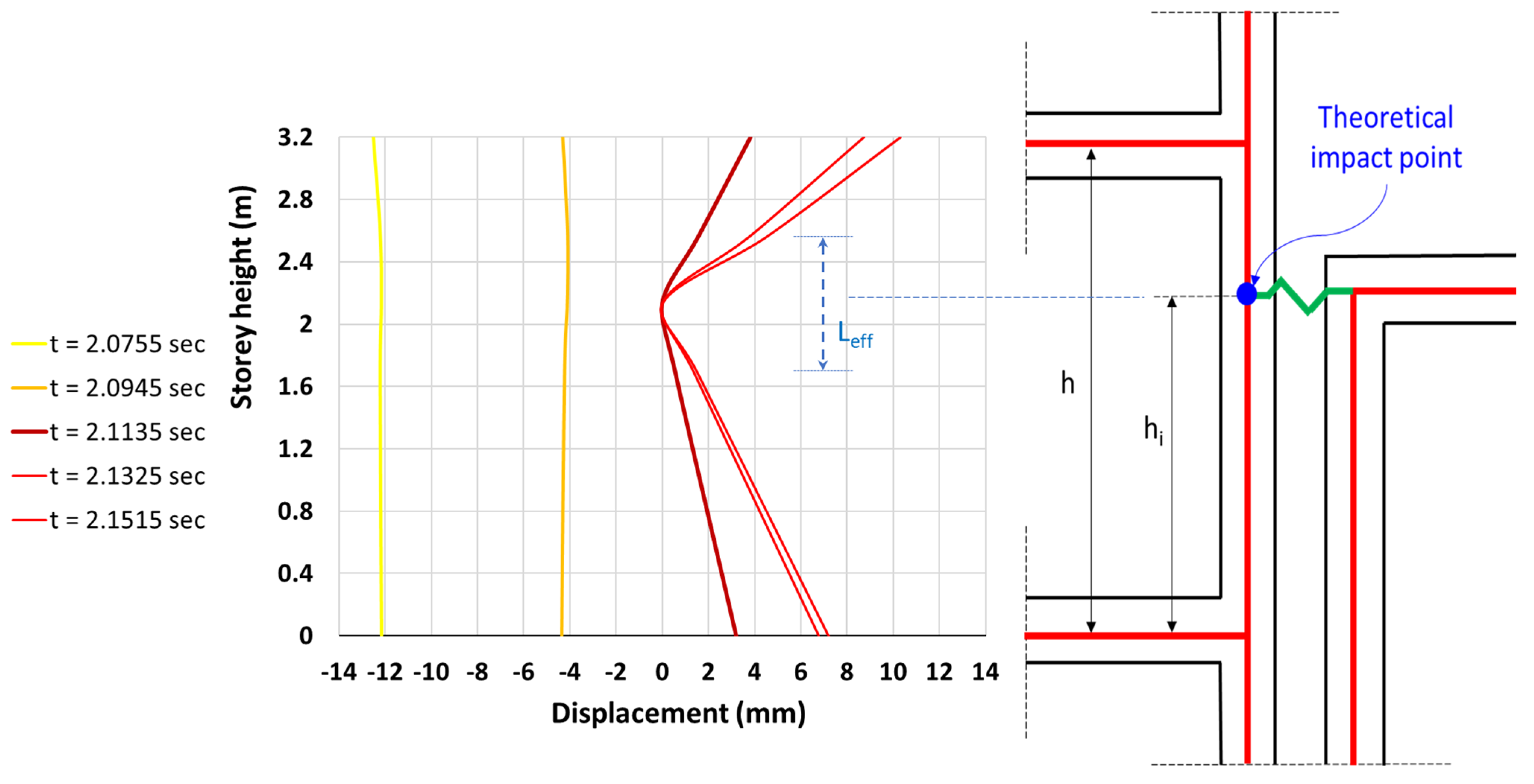
A key parameter involved in type-B pounding is the exact location of the theoretical impact point along the clear length of the external columns where a contact finite element is typically placed in the analysis models. This parameter is determined by the height h
i measured from the base of the columns (
Figure 3). In most relevant studies, the theoretical impact point height is expressed as a pre-defined percentage of the storey height h. Manoukas and Karayannis [
11,
17], Karayannis and Manoukas [
18], and Karayannis and Naoum [
19] adopted a value equal to (2/3)h, which is often observed in current practice. For example, the ground storey of many buildings houses stores with mezzanine floors and, as a consequence, its height is around 5 m. Normally, the adjacent buildings have storey heights between 3.0 m and 3.5 m; i.e., the ratio h
i/h ranges from about 0.6 to 0.7. Other researchers assumed that h
i is equal to h/2 [
23]. Very few studies considered varying values of h
i and investigated its influence on the seismic response. Karayannis and Favvata [
12] examined 36 type-B pounding cases between reinforced concrete planar frames considering that h
i is equal to either one-third or two-thirds of the storey height. The results obtained do not clearly indicate which one of the two values is more unfavorable in terms of the ductility demands and shear response of columns. Miari and Jankowski [
34] studied the symmetric seismic interaction between three-dimensional reinforced concrete buildings adopting three alternative values for h
i/h: 1/3, 1/2 and 2/3. According to the results presented, the influence of h
i/h variation on the shear forces of columns seems to be negligible. It is obvious that the relevant studies published in the literature are very limited and their quite ambiguous results do not permit the derivation of secure and concrete conclusions. Furthermore, they focus on symmetric seismic interaction while the asymmetric one is not addressed at all. Thus, more extensive investigation needs to be conducted regarding this critical issue.
The term seismic joint designates a separation gap a few cm wide, intentionally incorporated into the design of adjacent buildings in order to prevent collisions due to ground motion. Seismic joints allow the buildings to vibrate independently, helping to reduce the risk of damage during an earthquake. Seismic joints are not necessary in the foundation and, typically, they are limited to the superstructure. Concerning the separation gap size, all publications investigating its influence agree that, in general, the larger it is, the less structural damage occurs. However, exceptions from this generalized conclusion are not surprising. This is attributed to the nature of the inelastic seismic response and, more specifically, to the inherent uncertainties of the seismic interaction phenomenon. Indeed, such exceptions are reported in several studies [
7,
12,
14]. Nevertheless, this finding has not yet been sufficiently stressed, explained, and interpreted. Thus, many engineering practitioners and building constructors think that ensuring even a small gap size is always beneficial and mitigates the seismic interaction consequences. This misbelief enables the risk of misapplication of code provisions imposing a minimum seismic joint width.
The simplified structural models usually utilized for the analysis of interacting structures indicate that the whole height of a column that undergoes significant pounding forces is affected. In particular, the shorter of the two parts in which the column is divided by the theoretical impact point experiences excessive shear forces (
Figure 4a). However, as resulted from experimental studies [
49,
50] as well as from field observations (
Figure 4b), severe shear damage is concentrated to a small part of the column with lengths of about 1 m or less. This length is characterized as the effective impact length L
eff (
Figure 4c). Typically, L
eff lies at the floor level of the adjacent structure. It is apparent that a reliable estimation of the effective impact length is of great importance because it permits engineers to focus on this area during the initial design process of new buildings or the suggestion of retrofitting measures of existing buildings.
The present paper deals with the asymmetric seismic interaction between multistorey reinforced concrete buildings. The paper focuses on the so-called floor-to-column pounding and aims to identify the influence of two specific factors: the exact impact point location and the width of the pre-existing separation gap between the interacting structures. For this purpose, several interaction cases are analyzed by means of inelastic dynamic analysis. These cases involve two eight-storey buildings designed according to Eurocodes 2 and 8 [
51,
52] which interact with adjacent lower structures. Three alternative impact point locations and four values of separation gap width are supposed. Representative response quantities like floor rotations and translations, storey drifts, column shear forces, and plastic rotation demands are calculated. Furthermore, the estimation of the effective impact length is attempted by applying a well-documented analytical procedure [
49]. The whole investigation highlights the crucial role of the impact point location. It also reveals that the existence of inadequate seismic joints may be more unfavorable in comparison with the complete absence of separation between the interacting structures. Finally, the investigation confirms field observations and experimental results related to the effective impact length.
2. Asymmetric Seismic Interaction Cases Under Consideration
Herein, an extensive parametric study is conducted aiming to evaluate the seismic response of two eight-storey reinforced concrete frame buildings (
Figure 5) which interact with shorter structures. The two buildings were designed according to the European codes [
51,
52] in the context of previous studies [
17,
18]. Their structural systems are identical and the only difference between them is that the one is fully infilled with masonry panels while the other has soft ground storey (pilotis configuration).
The eight-storey buildings interact with three shorter structures: a one-storey very stiff (rigid) structure (building “1”) and three-storey and six-storey common reinforced concrete buildings (buildings “3” and “6”, respectively). Their plan view and the outline of their view in elevation are shown in
Figure 6. Building “1” is a virtual structure which is modeled by fixing one node of the “gap” elements simulating the contact area. Buildings “3” and “6” are common reinforced concrete frame buildings designed according to Eurocodes 2 and 8 [
51,
52]. Both are fully infilled with 10 cm thick masonry panels. The material properties, the modeling assumptions, the seismic loading parameters, and the analysis method applied for their design are identical to those adopted for the eight-storey buildings [
17,
18].
The layout of the interacting buildings (
Figure 7a) is such that they are in partial contact or they come into partial contact during an earthquake. Thus, the seismic interaction between them is asymmetric; i.e., torsional vibrations of the floors around the vertical axis are induced. It is considered that the contact is limited at two points per floor only (columns Κ4 and Κ8), as illustrated in
Figure 7b. For example, for seismic interaction between buildings “infilled” and “6”, there are 12 impact points. These points lie at the floor levels of the shorter structure. This choice is adopted by almost all similar studies because it is consistent with field observations which indicate that collisions take place mainly at these levels. In addition, the damage of the external columns is concentrated in a small area around them (effective impact length). Considering additional impact points (e.g., at the floor levels of the higher structure) would not alter the local behavior of the external columns of the eight-storey buildings, whereas the overall response depends only on the characteristics of the contact point at the shorter structure’s top floor [
12]. As has been demonstrated in the past [
17,
18,
19], in cases where the collisions take place at few points per floor lying far from the rigidity axis of the buildings, the torsional and overall responses are maximized.
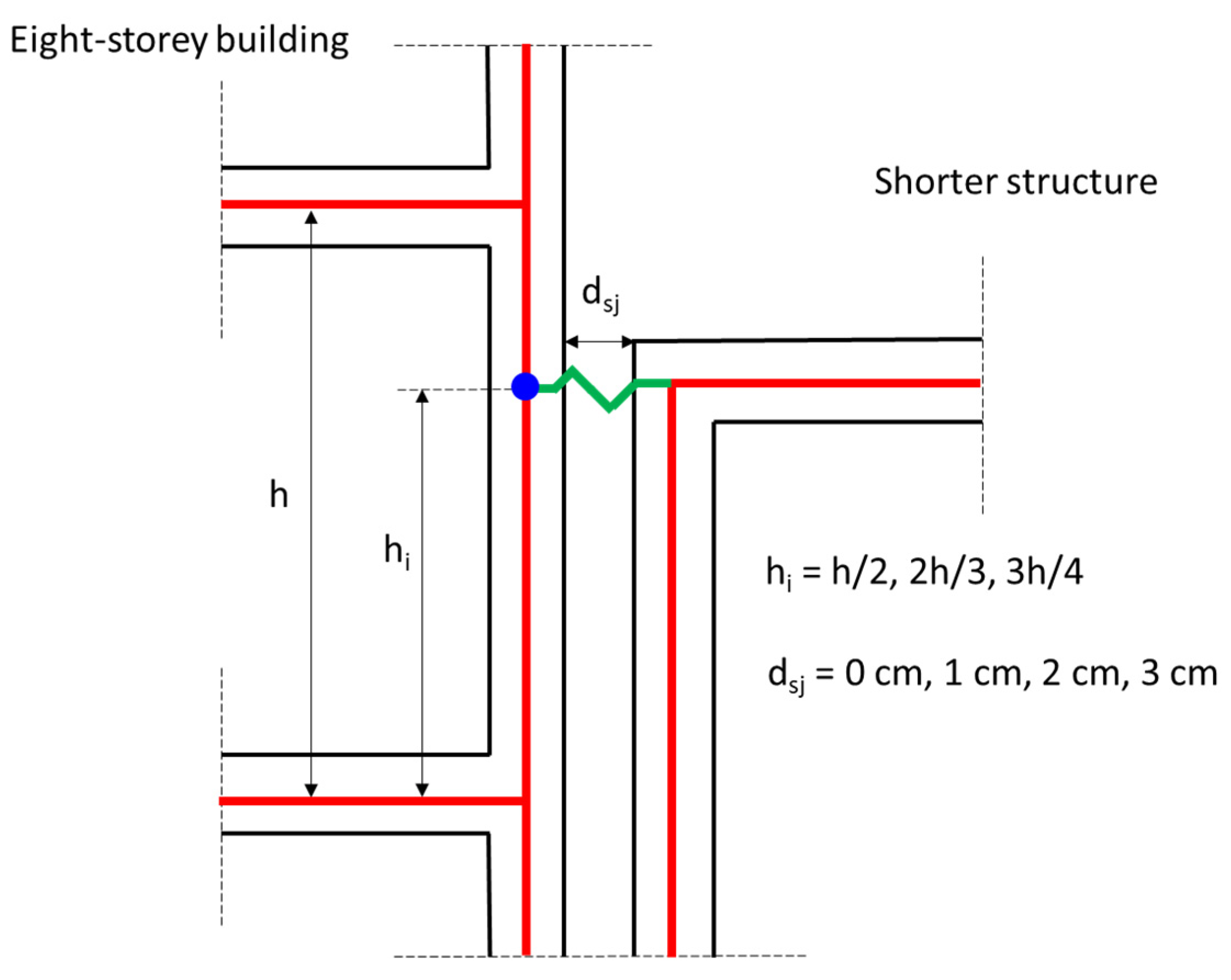
Three alternatives for the exact location of the impact points at each storey of the eight-storey buildings are adopted. In particular, it is considered that the distance h
i of the impact points from the floor immediately below is equal to 1/2, 2/3, or 3/4 of the storey height. Thus, floor-to-column pounding always occurs. In order to achieve the pre-defined impact point heights, the storey levels of the adjacent buildings are properly adapted. Namely, three variants of each building, “1”, “3”, and “6”, are considered.
Table 1 tabulates the storey heights for each variant, while
Table 2 shows the natural periods and the modal participating mass ratios of modes 1 and 4, which dominate the seismic response of buildings “3” and “6” along the X direction. Given that building “1” is rigid, no dynamic characteristics can be calculated (T
In addition, four different values of the seismic joint width d
sj are taken into account: 0 cm, 1 cm, 2 cm, and 3 cm. The selected values of h
i and d
sj are tabulated in
Figure 8.
Seven series of asymmetric seismic interaction cases are examined. Each one of them is symbolized by a string symbol consisting of three parts. The first part is an uppercase letter (P or I) indicating which one of the eight-storey buildings is involved (“Pilotis” or “Infilled”). The second part is a number (1, 3 or 6) corresponding to the lower interacting structure (buildings “1”, “3” or “6”). The third part comprises three lowercase letters (ipl or sjw); ipl and sjw denote that the objective of the specific analysis series is the influence of the impact point location and the seismic joint width, respectively. For example, the symbol P3sjw designates a series of pounding cases between the eight-storey “pilotis” and “3” buildings, aiming to investigate the influence of the seismic joint width. The seven analysis series are the following:
P1ipl: Asymmetric seismic interaction between “pilotis” and “1” buildings for varying impact point location (hi = h/2, 2h/3, 3h/4) and constant seismic joint width (dsj = 0 cm);
I1ipl: Asymmetric seismic interaction between “infilled” and “1” buildings for varying impact point location (hi = h/2, 2h/3, 3h/4) and constant seismic joint width (dsj = 0 cm);
I3ipl: Asymmetric seismic interaction between “infilled” and “3” buildings for varying impact point location (hi = h/2, 2h/3, 3h/4) and constant seismic joint width (dsj = 0 cm);
I6ipl: Asymmetric seismic interaction between “infilled” and “6” buildings for varying impact point location (hi = h/2, 2h/3, 3h/4) and constant seismic joint width (dsj = 0 cm);
P1sjw: Asymmetric seismic interaction between “pilotis” and “1” buildings for varying seismic joint width (dsj = 0 cm, 1 cm, 2 cm) and constant impact point location (hi = 2h/3);
I1sjw: Asymmetric seismic interaction between “infilled” and “1” buildings for varying seismic joint width (dsj = 0 cm, 1 cm, 2 cm) and constant impact point location (hi = 2h/3);
I3sjw: Asymmetric seismic interaction between “infilled” and “3” buildings for varying seismic joint width (dsj = 0 cm, 1 cm, 2 cm, 3 cm) and constant impact point location (hi = 2h/3).
The interacting pairs of buildings are subjected to two unscaled recorded accelerograms with peak ground acceleration almost equal to the design acceleration (≈0.30 g). The accelerograms are applied along the horizontal X axis for both directions (positive and negative). The seismic component along the Y direction is not taken into account because it is not expected to considerably alter the effects of the pounding phenomenon which critically affects the response quantities along the X direction. Thus, the present study is directly comparable with almost all similar studies in the past which also used unidirectional seismic excitation. In addition, this choice contributes to highlighting the torsional effects of seismic interaction since floor rotations due to multidirectional excitation are precluded. The four alternative seismic excitations considered are listed in
Table 3. Representative response quantities such as floor translations and rotations, storey drifts, column shear forces, and plastic rotation demands are calculated. For this purpose, inelastic dynamic analysis is implemented with the aid of the SAP2000 program. For comparison purposes, non-linear analysis results for the eight-storey buildings without pounding are obtained from previous studies [
17,
18].
More information regarding the structural modeling and analysis of the buildings, including the simulation of masonry panels, can be found in references [
17,
18]. It is worth noting that soil–structure interaction is not taken into account and the supports are considered fixed at the base. The soil–structure interaction’s effects on the severity of seismic pounding phenomena are quite ambiguous, since the relevant publications [
33,
34,
35,
36,
37] report contradictory results. The investigation of this important issue is beyond the objective of the present study. The contact area is simulated by appropriate “gap” elements available in the software with non-linear behavior described in detail in references [
11,
17]. It can be deduced from the literature [
5,
7,
8,
17,
18,
19,
35,
42] that the stiffness and damping of these elements do not really influence the seismic response. After a sensitivity analysis which confirmed this conclusion, the values k = 10
9 kN/m and c = 0 kNs/m were selected for the element stiffness and damping, respectively.
3. Influence of the Exact Impact Point Location
As demonstrated by several publications available in the literature [
11,
12,
13,
17,
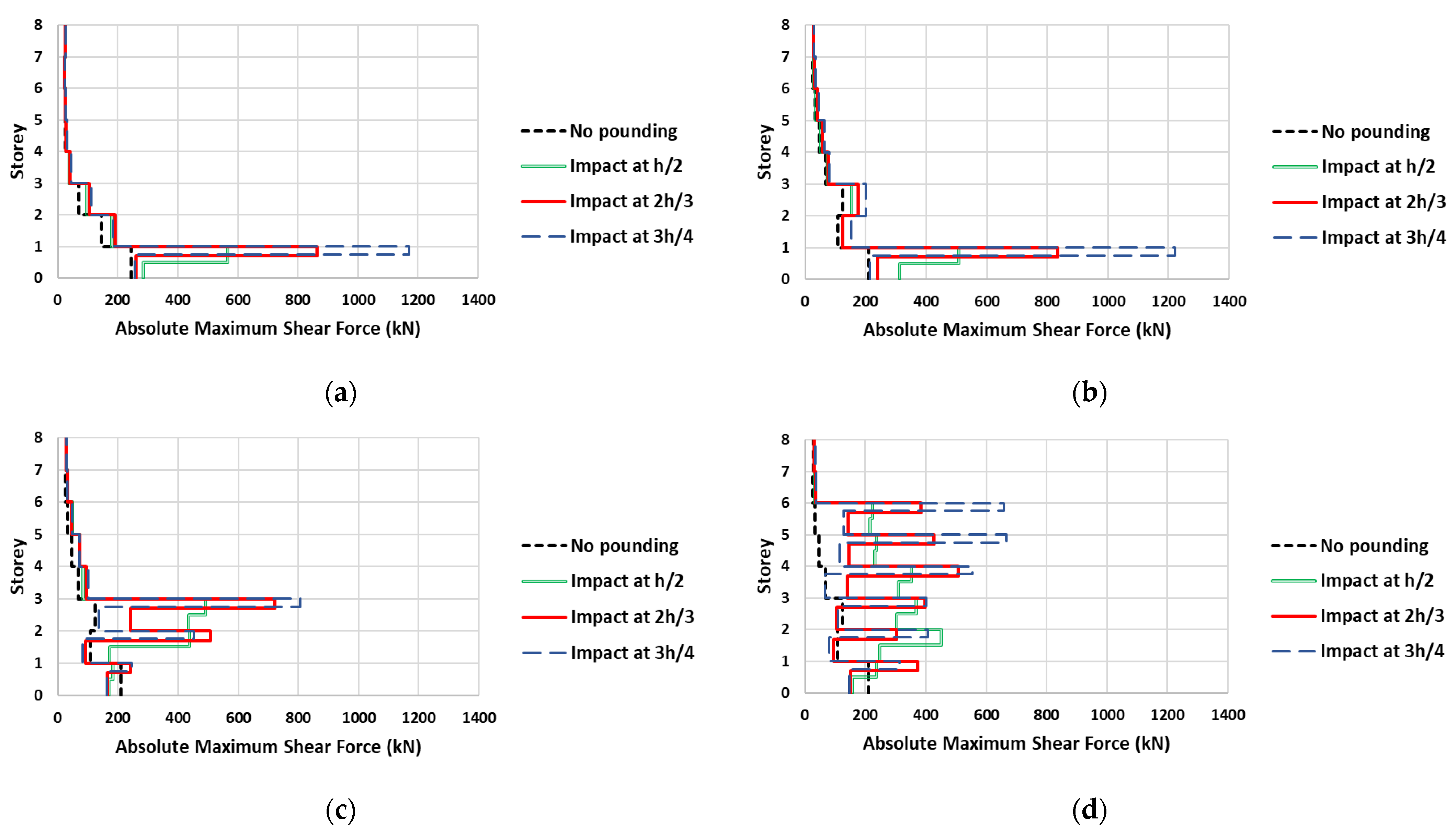
18], the most serious implication of floor-to-column pounding is probably the local shear damage of the external columns directly struck by the slabs of the adjacent structure. Indeed, this conclusion is confirmed by the results of the present study. Indicatively, the maximum absolute shear forces along the height of column Κ4 due to excitation “1+” are illustrated in
Figure 9. More specifically, the figure presents the shear forces along the X axis for the first four analysis series (P1ipl, I1ipl, I3ipl, I6ipl). The dashed black lines represent the developing shear forces without pounding, while the double green, solid red, and dashed blue lines correspond to impact point heights equal to h/2, 2h/3 and 3h/4, respectively. Furthermore,
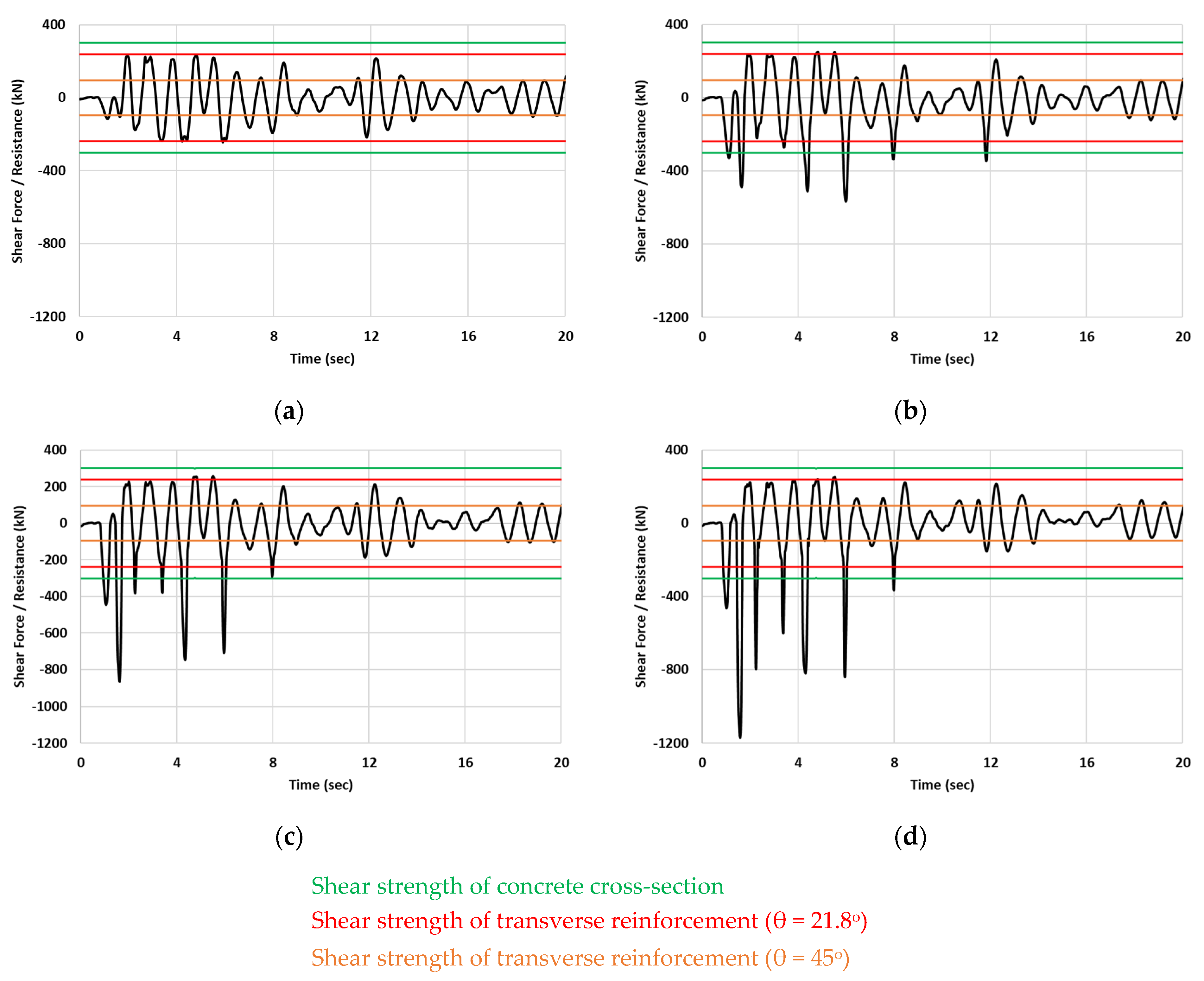
Figure 10 presents the variation in shear forces of column Κ4 along the X axis at the top of the first storey due to the first 20 s of “1+” excitation for the P1ipl analysis series. The shear resistances of the column cross-section and the transverse reinforcement, determined according to Eurocode 2 [
51] for the two limits of the crack angle θ, are plotted as well. These resistances are calculated using the mean values of material properties without any safety factors. Based on
Figure 9 and
Figure 10, several interesting observations can be made. As expected, an outbreak of shear forces is observed at all stories where collisions take place. On the contrary, the shear forces of the upper stories are only slightly affected. Column Κ4 is divided into two parts by the theoretical impact point. The upper part always experiences a larger shear force than the lower one. Moreover, the shorter the upper part is, the larger the shear force. In other words, the impact point height h
i = 3h/4 is the most unfavorable, while h
i = h/2 is the least unfavorable one. In particular, in relevance to the no-pounding case, the response is amplified up to about 7, 11, and 16 times for h
i equal to h/2, 2h/3, and 3h/4, respectively (I6ipl series, sixth storey). The developing shear forces exceed the corresponding shear resistance (up to about 2, 3, and 4 times for h
i equal to h/2, 2h/3, and 3h/4, respectively) during a large number of analysis timesteps. This means that there is a high probability of brittle shear failure of the columns.
Figure 11 illustrates the maximum absolute plastic rotation demands along the height of column Κ4 due to excitation “1-”. More specifically,
Figure 11 presents the plastic rotations around the Y axis for the analysis series P1ipl and I6ipl. The corresponding capacities which are calculated in accordance with Eurocode 8, Part 3 [
53], are plotted as well. For the no-pounding case, plastic deformations occur at the ground storey only. The asymmetric seismic interaction between buildings “infilled” and “6” amplifies the deformation demands of the ground storey up to about 3.5 times regardless of the exact position of the impact point. Concerning the interaction between buildings “pilotis” and “1”, the amplification strongly depends on h
i. It is more pronounced for h
i = h/2 and 2h/3 (about two times), while for h
i = 3h/4, the plastic rotation demand increases about 50%. In addition, plastic deformations develop at the middle storeys (fourth, fifth, sixth) for the I6ipl analysis series (
Figure 11b). The plastic deformation capacities are exceeded by a maximum of about 2.5 times. This value corresponds to h
i = 2h/3.
The observations resulting from the study of shear forces and plastic rotation demands with regard to the influence of h
i are contradictory. Taking into account the number and the extent of deficiencies presented in
Figure 9,
Figure 10 and
Figure 11 and given the brittle nature of the shear behavior, it is concluded that the shear response of the columns is more critical than the flexural one. Consequently, the larger the impact point height is, the more unfavorable the situation.
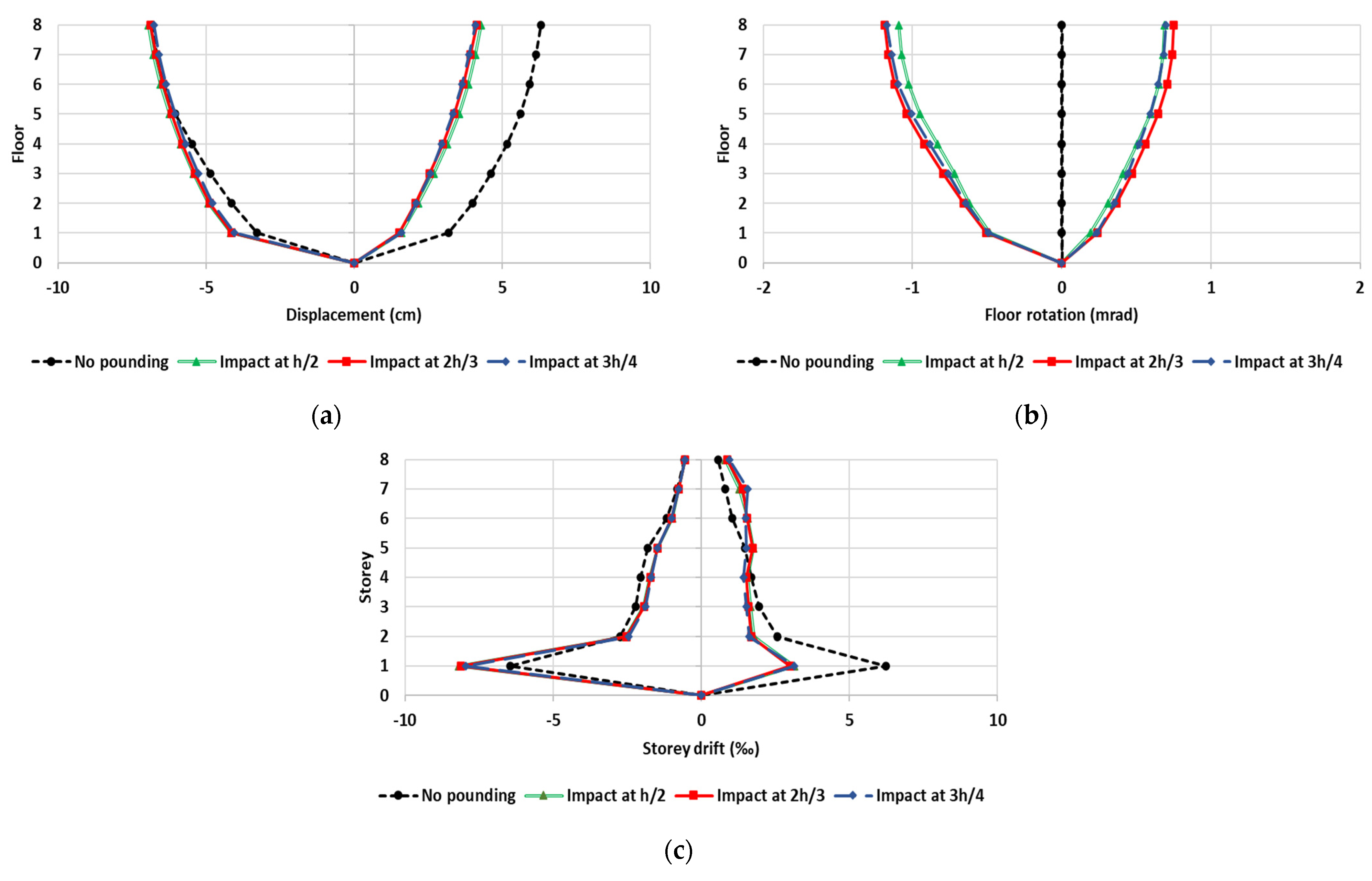
In contrast to the local response of columns suffering direct hits by the slabs of the adjoining structure, it seems that the overall response of the eight-storey buildings is not significantly affected by the variation in the impact point height. Apart from the shear and flexural response of column Κ4 at the upper stories where no collisions occur (see
Figure 9,
Figure 10 and
Figure 11), this conclusion is also documented by the plots of floor displacements and storey drifts. As an example, the minimum and maximum floor translations and rotations as well as storey drifts produced by the excitation “1-” for the analysis I6ipl are given in
Figure 12. It is apparent that the influence of h
i is negligible.
4. Influence of the Seismic Joint Width
The typical measure against the consequences of seismic interactions is the provision of a seismic joint (joint width d
sj) between the interacting structures. For reference purposes, it is worth reporting that the minimum values of d
sj specified by Eurocode 8 [
52] are 3 cm, 3.3–3.6 cm, and 6.5–6.8 cm for the interaction cases between the eight-storey and “1”, “3”, and “6” buildings, respectively. The influence of the joint width on the pounding problem has already been the subject of numerous papers in the literature [
7,
8,
12,
13,
14,
15,
16,
20,
24,
25,
26,
27,
28,
29,
30,
31,
32]. In general, the relevant publications are consistent in that by increasing the seismic joint width, the consequences of pounding are mitigated. However, many exceptions from this conclusion are reported in several studies [
7,
12,
14]. Nevertheless, although this is a key issue related to the destructiveness of the pounding effect, it has not been given due attention. Thus, many engineering practitioners and building constructors think that ensuring even a small gap size, which is not able to completely preclude pounding, is always beneficial for the structures. This misbelief enables the risk of misapplication of code provisions prescribing a minimum seismic joint width.
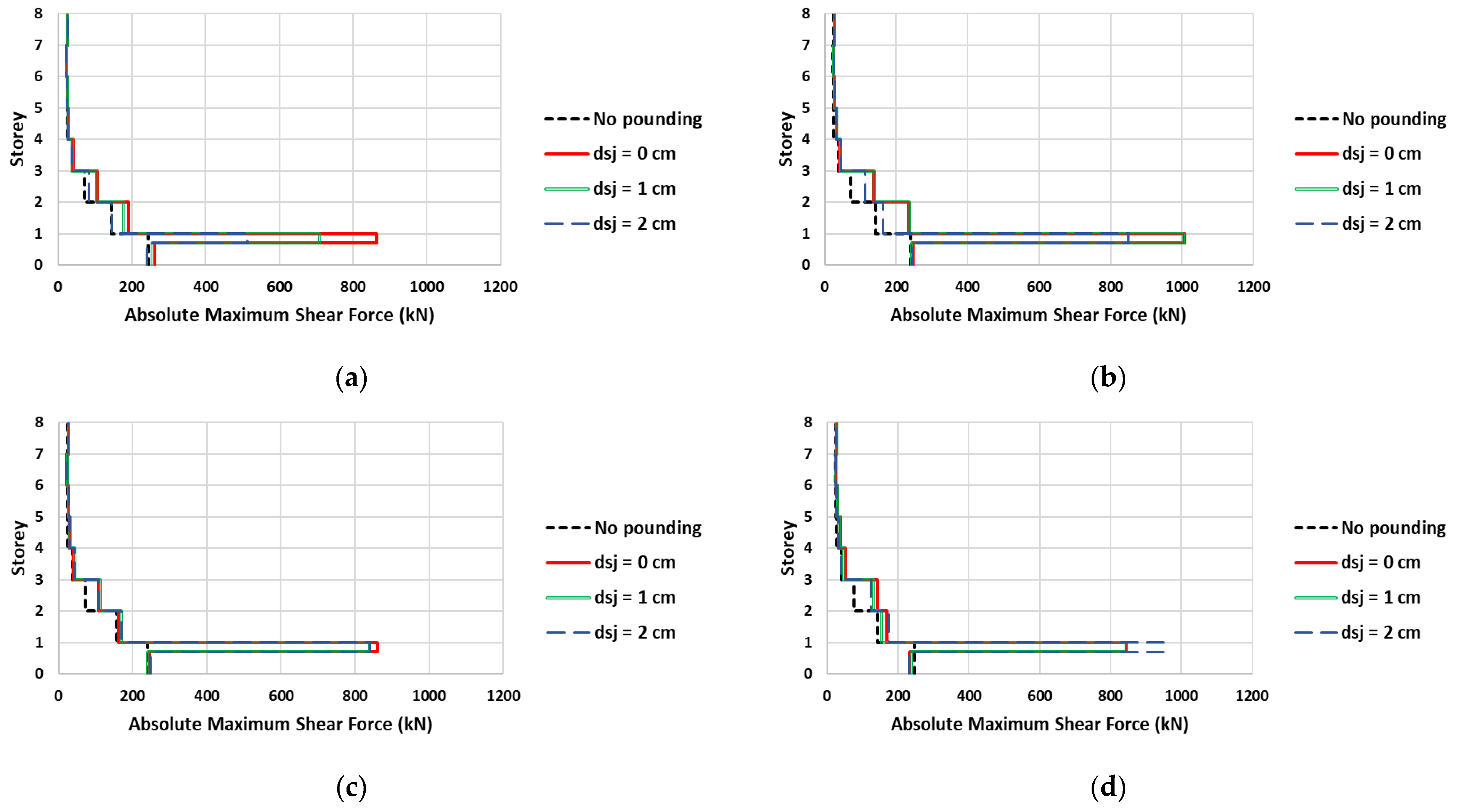
In
Figure 13, the influence of seismic joint width on the developing maximum absolute shear forces of column Κ4 along the X axis is presented. The figure refers to the interaction between “pilotis” and “1” buildings for d
sj equal to 0 cm, 1 cm, and 2 cm (analysis series P1sjw) and for the no-pounding case. The dashed black lines represent the developing shear forces without pounding, while the solid red, double green, and dashed blue lines correspond to seismic joint widths equal to 0 cm, 1 cm, and 2 cm, respectively. The impact point height is considered equal to 2h/3. It is apparent that the seismic interaction phenomenon leads to an excessive augmentation (up to four times) of the shear forces of the ground floor where the collisions take place. Concerning the influence of d
sj, while the results for excitation “1+” are consistent with the general trend reported in the literature, this is not the case for the remaining excitations. From
Figure 13b,c, it can be observed that small gaps do not really mitigate the impact consequences, since the developing shear forces resulting from the different values of d
sj are almost equal. Furthermore, for the “2-” excitation (
Figure 13d) column Κ4 experiences over 12% larger shear forces for d
sj = 2 cm in comparison with d
sj = 0 cm or 1 cm.
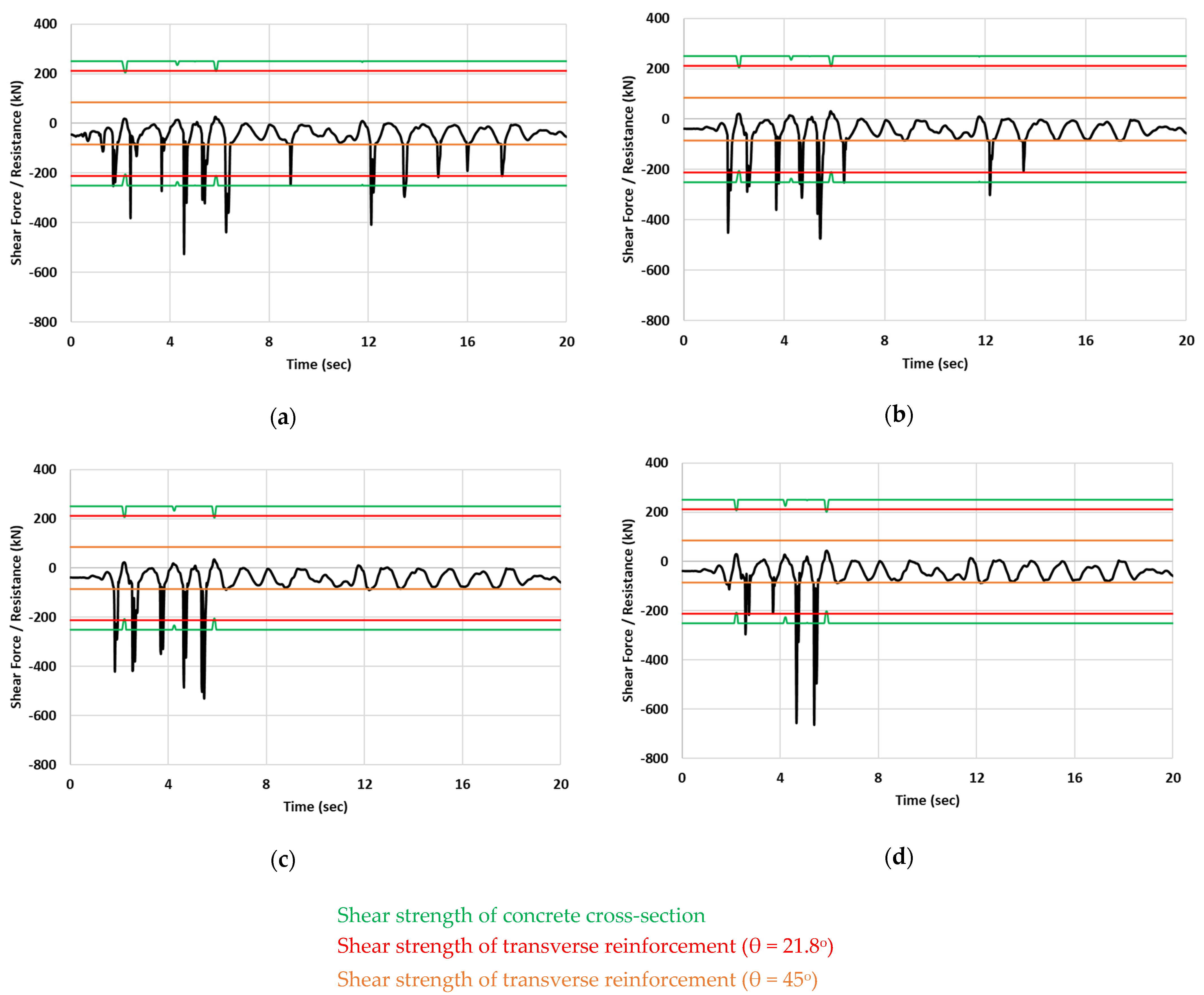
In
Figure 14, the time histories of the developing shear forces of column Κ4 along the X axis at the top of the third storey are presented. The figure refers to the I3sjw analysis series applying the first 20 s of the “1-” excitation. The shear resistances of the column cross-section and the transverse reinforcement, determined according to Eurocode 2 [
51] for the two limits of the crack angle θ, are plotted as well. These resistances are calculated using the mean values of material properties without any safety factors. The presented results include the time histories for (i) structures in contact (d
sj = 0 cm), (ii) structures that have a small separation gap equal to 1 cm (d
sj = 1 cm), (iii) structures that have a small separation gap equal to 2 cm (d
sj = 2 cm), and, finally, (iv) structures that have a small separation gap equal to 3 cm (d
sj = 3 cm). The results plotted in
Figure 14 support and verify the remarks extracted from
Figure 13. Indeed, it seems that the maximum shear force occurs for the largest width (d
sj = 3 cm) of the separation gap (over 25% larger than d
sj = 0 cm). Furthermore, it is emphasized that, regardless of the gap size, the developing shear forces exceed the shear strength of the column during seismic excitation many times over.
Similar findings can also be derived from the study of the deformation demands.
Figure 15 illustrates the maximum absolute plastic rotation demands along the height of column Κ4 due to excitation “1-” for the analysis series P1sjw and I1sjw, along with the corresponding capacities. The latter is calculated in accordance with Eurocode 8, Part 3 [
53].
Figure 15 illustrates the maximum absolute plastic rotation demands along the height of column Κ4 due to excitation “1-”. More specifically,
Figure 15 presents the plastic rotations around the Y axis for the analysis series P1sjw and I1sjw. The corresponding capacities, which are calculated in accordance with Eurocode 8, Part 3 [
53], are plotted as well. Obviously, the asymmetric seismic interaction amplifies the deformation demands of the ground storey even exceeding the corresponding capacity. Concerning the I1sjw analysis series, as anticipated, the amplification increases with decreasing d
sj (
Figure 15b). However, for the P1sjw analysis series (
Figure 15a), the deformation demands for d
sj = 2 cm are larger than those for d
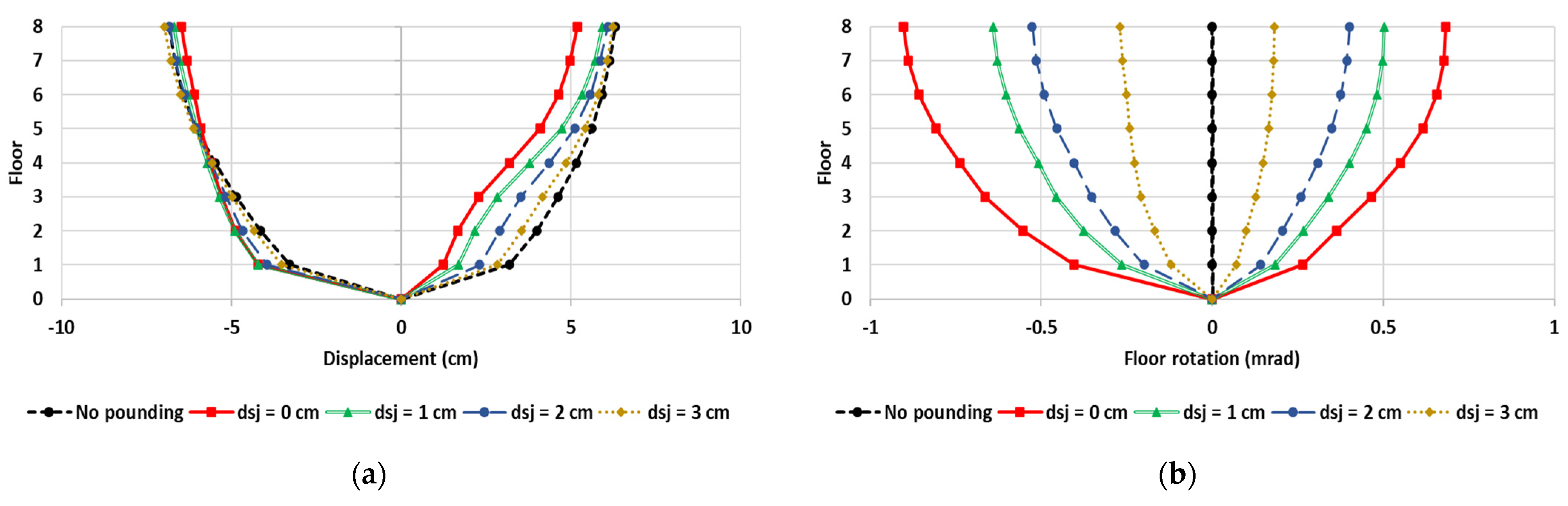
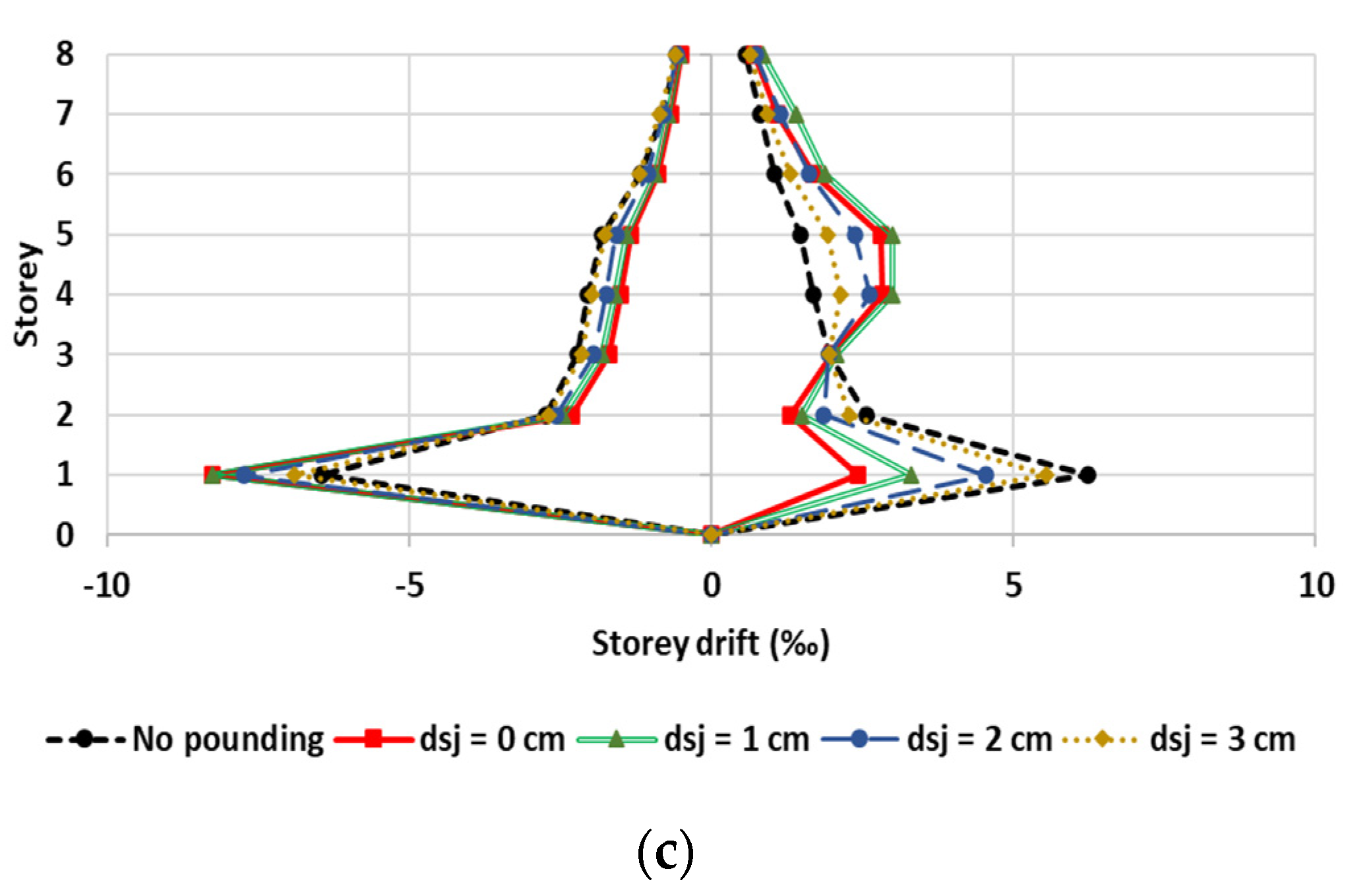
sj = 1 cm. Analogous observations can be made regarding the floor displacements and storey drifts. As an example, the minimum and maximum floor translations and rotations as well as storey drifts produced by the excitation “1-” for the analysis I3sjw are given in
Figure 16. Such unexpected results have been reported by previous studies too [
7,
12,
14], but they have not yet been sufficiently explained and interpreted. In the authors’ opinion, they should be attributed to the inherent uncertainty of the non-linear behavior. In particular, the ensemble of the interacting structures constitutes a complicated dynamic system with unknown dynamic characteristics (natural periods and modes cannot be determined) which depend on d
sj. This fact, in conjunction with the frequency content of the ground motion, might cause such peculiar results. However, this conclusion is very difficult to verify. Conclusively, keeping small seismic joints, not efficient to completely preclude pounding, may not mitigate the consequences of asymmetric seismic interaction.
Figure 15 and
Figure 16 confirm some important findings of previous studies [
11,
17,
18]. In particular, comparing
Figure 15a,b, it is deduced that the pilotis building experiences much larger inelastic deformations than the fully infilled one. Similar trends are observed for the remaining response quantities, too. The unfavorable role of the soft ground storey has been highlighted many times in the past [
11,
17,
18], so the present study does not further investigate this issue. In addition,
Figure 16b indicates that asymmetric seismic interaction induces rotations of the diaphragms. These rotations lead to significant amplification of the response quantities along the X direction, while they cause a considerable response along the transverse direction, too. For example, a diaphragm rotation equal to 1 mrad leads to an additional translation of column K4 equal to 1.8 cm and 0.9 cm along the X and Y axes, respectively.
5. Estimation of the Effective Impact Length
The term “effective impact length” L
eff is related to the floor-to-floor seismic interaction and more specifically to the columns struck by the slabs of the adjacent structure. It designates the area of the columns where the (mainly shear) damage is concentrated. Experimental studies and field observations indicated that L
eff ranges around 1 m or less. It is apparent that a reliable estimation of the effective impact length is of great importance because it permits engineers to focus on this area during the initial design process of new buildings or the suggestion of retrofitting measures of existing buildings. On the basis of an extensive analytical and experimental study, Kotsovos [
49] proposed a simplified analytical methodology for the calculation of L
eff. This methodology was successfully applied by other researchers too [
50], in the context of an experimental work on full-scale beams suffering a high-energy impact at their mid-span.
The whole procedure is based on the loading rate of the pounding force and on the properties of the structural member subjected to the impact. In particular, L
eff is estimated from the following relation:
where v is the velocity of the shear stress wave produced by the impact and t* is the time needed for crack development at the external face of the member. The shear stress wave velocity depends on the shear modulus G and the density ρ of the member’s material:
The time interval t* is calculated from the following equations:
where M is the bending moment required for the beginning of cracking, Ρ
max is the maximum pounding force, t is the time needed to reach Ρ
max, and Ρ* is the loading rate of the pounding force. M depends on the material’s tensile strength, the cross-sectional dimensions, and the stress due to seismic and gravity loading.
Herein, the analytical methodology presented above is implemented for the first time in a seismic interaction problem. Obviously, during an earthquake excitation, there are discrete time intervals where the interacting structures are in contact and large pounding forces develop. Between these time intervals, the structures vibrate independently from each other and the pounding forces are equalized to zero. This constitutes a key difference that diversifies a seismic interaction problem from a typical impact problem like those studied in the past (e.g., [
49,
50]); in the former, multiple impacts take place. For the implementation of the methodology, the most intense one (i.e., the one that produces the largest pounding force) is selected. Thus, as a first step, on the basis of inelastic dynamic analysis results, the maximum value of the pounding force should be detected. Subsequently, in order to determine the loading rate with acceptable accuracy, the non-linear analysis should be repeated using a very small integration timestep (e.g., 0.0001 s) for a time period comprising the peak pounding force. Obviously, this implies excessive computational effort. Hence, for the sake of simplicity, two seismic interaction cases where the most intense impact occurs at the first few seconds of the excitation are selected: one between “pilotis” and “3” buildings for the “1+” excitation (“P3-1+”) and a second between “infilled” and “3” buildings for the “2-” excitation (“I3-2-”). For both cases, it is considered that the interacting structures are in contact from the beginning (d
sj = 0 cm) while the theoretical impact point height is equal to 2h/3. The time histories of the pounding forces acting on the third storey of column Κ4 during the first few seconds of the seismic excitations are plotted in
Figure 17. The significant difference between the maximum pounding forces resulting from the two cases is not surprising. It is attributed to the different stiffness of “pilotis” and “infilled” buildings as well as to the different seismic loading. The concrete grade is C20/25 according to the European standards and its properties are obtained from Eurocode 2 [
51]: G = 12.5 GPa, ρ = 2.5 t/m
3, and f = 2.2 MPa. From these values of G and ρ results v = 2236 m/s. The remaining calculations needed for the implementation of the methodology are tabulated in
Table 4. It is worth noting that, given the structural properties of column K4, the most impactful parameter is the loading rate [
54], which takes relatively large values. The calculated values of L
eff confirm previous experimental results as well as site observations, which indicate that severe damage is limited to a relatively small area of columns no more than 1 m in length.
Furthermore, in
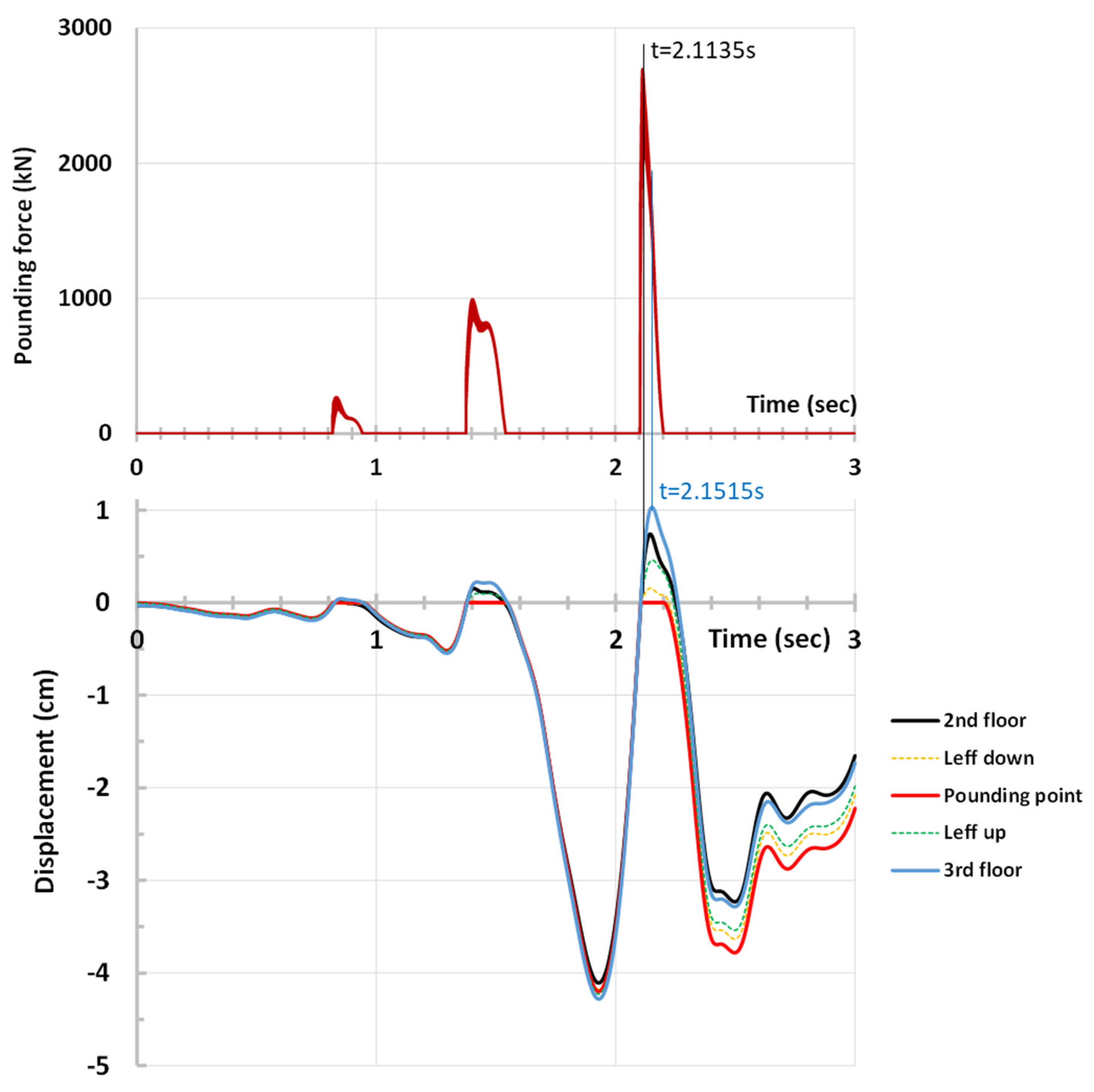
Figure 18, the time history of the pounding force acting on the third storey of column K4 (also shown in
Figure 17a) along with the time histories of the displacements of characteristic points of the same column for interaction case “P3-1+” are illustrated. In particular, five points are selected from bottom to top: the bottom (second floor level), the lower point of the effective impact length, the theoretical impact point, the upper point of the effective impact length, and the top (third floor level). The time points where the pounding force and the displacements are maximized are highlighted (t = 2.1135 s and t = 2.1515 s, respectively). In addition,
Figure 19 illustrates the deformation of column K4 in the third storey at discrete time points around the moment that the pounding force is maximized. Starting from the time that the displacements are minimized (around t = 1.9 s—
Figure 18) and the interacting buildings vibrate independently, it is apparent that the “pilotis” building moves towards building “3” until a collision takes place just before t = 2.1135 s. At that moment, the pounding force starts to increase rapidly and, in a very short time period, is maximized. Concurrently, the displacements continue to increase and take their maximum value 0.038 s after the pounding force. From this point on, the “pilotis” building starts to move away from building “3”. From
Figure 19, it can be observed that during the contact of the interacting buildings, the effective impact length of column K4 experiences extensive inelastic deformations.
6. Conclusions
The present paper deals with the asymmetric seismic interaction between multistorey reinforced concrete buildings. The paper focuses on the so-called floor-to-column pounding and aims to identify the influence of two specific factors: the exact impact point location and the width of the pre-existing separation gap between the interacting structures. For this purpose, several interaction cases involving two eight-storey buildings designed according to Eurocodes 2 and 8, which interact with adjacent lower structures, are analyzed by means of inelastic dynamic analysis. Three alternative impact point locations and four values of separation gap width are supposed. Representative response quantities like floor rotations and translations, storey drifts, column shear forces, and plastic rotation demands are calculated. Furthermore, the estimation of the effective impact length is attempted by applying a well-documented analytical procedure.
The main findings of the present study are the following:
The exact impact point location strongly influences the local response of the columns directly suffering the impact within their clear height. However, it seems that the overall structural response is not considerably affected.
Floor-to-column asymmetric seismic interaction amplifies both shear and flexural responses of the struck columns (up to 16 and 2 times, respectively), leading to significant exceedance of the corresponding resistances (up to 4 and 2.5 times, respectively).
Given that shear behavior is the most critical behavior, the larger the impact point height is, the more unfavorable the situation.
Small seismic joints, not efficient to preclude pounding, may not be beneficial for the seismic response of interacting structures. On the contrary, they might significantly increase the response in comparison with the case of no seismic joint (for example, up to 25% for the column shear forces). Thus, the relevant code provisions should be strictly abided by in order to completely prevent collisions between adjacent buildings.
Pilotis configuration amplifies the capacity demands of structural members.
Asymmetric pounding induces torsional vibrations of the floor diaphragms which considerably affect the overall seismic response.
The effective impact length, i.e., the length of a column directly suffering the impact where severe damage is concentrated, is about 1 m or less and it can be reliably estimated by a simple analytical procedure. Obviously, this is quite useful for the design of new buildings as well as the retrofitting of existing buildings prone to floor-to-column seismic pounding.
Based on the aforementioned findings, useful suggestions in order to reduce the pounding consequences can be derived. As has already been stated, the most simple and efficient measure is to apply seismic joints of adequate width. Concerning the rehabilitation of existing buildings, the engineering practitioners should take special care for local strengthening of the effective impact length of external columns. In addition, the construction of reinforced concrete walls at appropriate locations would radically reduce the displacements (including the diaphragm rotations) and would lead to an improvement in the overall response. Finally, the application of various types of dampers is a promising alternative.
In order to generalize the derivations listed above, further investigation is required, involving various building typologies such as asymmetric in-plan, dual, wall, torsionally flexible, or inverted pendulum systems. Another interesting issue to be investigated is the potential non-linear effects of materials at different gap widths, especially in buildings constructed with varying materials or in non-ideal conditions. Furthermore, the severity of seismic pounding in zones with different seismic hazard levels, particularly in regions with low seismic activity, should be evaluated. Finally, the influence of additional parameters on the phenomenon, such as the soil–structure interaction effects and the number of impact points, is of great interest for forthcoming investigations.


