Article

Bending Performance of Steel-Reinforced Concrete Beams Strengthened with Highly Ductile Cementitious Composites in the Compression Zone

1
Key Laboratory of Safe Construction and Intelligent Maintenance of Urban Shield Tunnels of Zhejiang Province, Hangzhou City University, Hangzhou 310015, China
2
School of Engineering and Architecture, Zhejiang Sci-Tech University, Hangzhou 310018, China
3
School of Civil Engineering, Harbin Institute of Technology, Harbin 150090, China
*
Author to whom correspondence should be addressed.
Buildings 2025, 15(4), 510; https://doi.org/10.3390/buildings15040510
Submission received: 31 December 2024 / Revised: 23 January 2025 / Accepted: 4 February 2025 / Published: 7 February 2025
(This article belongs to the Section Building Materials, and Repair & Renovation)

Abstract

By replacing ordinary concrete in the compressed zone with high-ductility materials, it is possible to improve the ductility of reinforced concrete beams. The effects of the properties of the materials in the compressed zone and the height of the zone on the performance of steel-reinforced concrete beams were investigated experimentally and theoretically. The performances of the steel-reinforced concrete beams strengthened with slurry infiltrated fiber concrete (SIFCON) in the compression zone were tested by four-point bending experiments. Based on an accurate validation of the experimental results, a parametric analysis using the finite strip method was conducted. The tested results show that after replacing the ordinary concrete in the compressed zone with SIFCON, the strain distribution of the concrete beam cross-section remains linear along the height, adhering to the plane section assumption. An equation was developed using a strip method, and the prediction results showed an error of less than 11% compared to the experimental data. The theoretical calculations predict that the moment–curvature relationship of the beams enhanced with high-ductility-cement-based materials aligns well with the experimental results. This study reveals that adjusting the height, initial modulus, and compressive strength of compressed zone materials effectively enhances ductility, with minimal impact on load-bearing capacity. Increasing the material strength and height improves the ultimate curvature and maximum bending moment. The elastic modulus of the compressed zone has a greater effect on the ultimate curvature than on the maximum bending moment. With a replacement of the compressed zone height of 60 mm (section height 300 mm), the ultimate curvature increases by 177% when the elastic modulus of the material is increased by 2.5 times. The present study provides a calculation method for the retrofitting and reinforcement of over-reinforced concrete beams.

1. Introduction

The deformation capacity of concrete beams reinforced with fiber-reinforced composite bars or over-reinforced steel bars depends on the material properties of the plastic hinge region in the compressed zone [1,2,3,4]. By replacing the ordinary concrete in the compressed zone with high-ductility materials, the excellent compressive performance of high-ductility-cement-based composites can delay the failure of the concrete in the compressed zone, thus improving the ductility of reinforced concrete beams [5,6,7,8,9]. Compared to ordinary concrete, widely used high-ductility-cement-based composites include cement-based composites (ECCs) [10], ultra-high-performance fiber-reinforced concrete (UHPFRC) [11,12], strain-hardening cement-based composites (UHP-SHCCs) [13,14,15], and slurry infiltrated fiber concrete (SIFCON) [16,17], all of which exhibit significantly different compressive stress–strain relationships. The peak compressive strain of ECCs, UHPFRC, and UHP-SHCCs typically ranges from 0.3% to 0.5% [18,19,20], while the ultimate compressive strain of SIFCON can reach around 2% to 3% [3]. Research on the constitutive models of materials in the compressed zone and their influence on the compressed zone of reinforced concrete beams will provide valuable guidance for the design and preparation of materials used in the compressed zone.
By replacing the ordinary concrete in the compressed zone with high-ductility-cement-based composites, both the load-bearing capacity and ductility of reinforced concrete beams are enhanced [21]. Compared to ultra-reinforced concrete beams that rely on deformation in the compressed zone to achieve ductility, beams with a compressed zone replaced by steel fiber concrete exhibit better deformation capacity [22]. Compared to BFRP-reinforced concrete beams with ordinary concrete (compressive strength 47.2 MPa and elastic modulus 34.49 MPa), replacing the compressed zone concrete with a 90 mm ECC yield block (compressive strength 38.3 MPa and elastic modulus 15.50 MPa) resulted in a 33.8% increase in the load-bearing capacity and a 33.0% improvement in the deformation capacity for BFRP-reinforced concrete beams [23]. When the compressed zone was replaced with heights of 20 mm and 30 mm, the deformation capacity of the reinforced concrete beams increased by 27.45% and 41.83%, respectively. As the height of the compressed zone increases, both the load-bearing capacity and deformation capacity of the beams improve [24].
The compressive constitutive model of cement-based composites in the compressed zone is a key factor influencing the mechanical performance of reinforced concrete beams [25]. Compared to using UHPC to replace the concrete in the compressed zone, replacing it with UDC (compressive strength 67.5 MPa and compressive strain 0.495%) results in a 58.9% decrease in the load-bearing capacity but a 30.4% increase in the deformation capacity. This is primarily because UHPC has a 49.1% higher compressive strength than HDC, but its deformation capacity is inferior to that of HDC [26]. When SIFCON with a compressive strength of 42 MPa was used to replace the concrete in the compressed zone, the load-bearing capacity of the concrete beams increased by 115.0%, while the energy absorption capacity improved by 137.2% [27]. The fiber content of normal fiber-reinforced concrete typically ranges from 1% to 3% by volume, while the fiber content of SIFCON ranges from 5% to 20% [28]. The matrix of SIFCON consists of a low-viscosity, cementitious slurry, in contrast to the regular concrete used in normal fiber-reinforced concrete.
The present study aims to improve the ductility of over-reinforced concrete beams. This approach of replacing materials in the compressed zone serves as a useful tool for selecting an appropriate strengthening scheme during the design phase of practical projects. Compared to demolition and reconstruction, this method only requires replacing a portion of the compressed zone with high-ductility-cement-based materials, making it a more cost-effective solution. In the present study, the influence of the SIFCON material in the compressed zone on the stress and strain distribution in ultra-reinforced concrete beams was investigated experimentally. Based on this, a strip method calculation approach is established for ultra-reinforced concrete beams with cement-based composites in the compressed zone. After validating the experimental results, this study proceeds to examine the impact of the constitutive model of cement-based composites in the compressed zone on the mechanical performance of ultra-reinforced concrete beams.

2. Materials and Methods

2.1. Raw Materials

The experiment uses PII 52.5 grade Portland cement, which was bought at Hangzhou, China. The coarse aggregate consists of continuously graded crushed stone with a particle size ranging from 5 to 20 mm. The fine aggregate is river sand with a fineness modulus of 2.65. The concrete mix ratio was designed according to the GB/T 50010-2010 standard [29]. The mix ratio and the compressive strength of the concrete are presented in Table 1. Cubic specimens of 150 mm3 were cured in standard conditions for 28 days. The compressive strength was determined through axial compression tests, with the average compressive strength of three sets of specimens taken as the 28-day compressive strength.
The cement-based composite material for the compression zone is a type of SIFCON, which is prepared from cement, fine sand, fly ash, steel fibers, silica fume, a superplasticizer, and water, with the mix proportions shown in Table 2. The mix proportions were developed by our group, and the detailed proportions are referenced to Ref. [28]. The cement used is PII 52.5 grade Portland cement. Class I fly ash is employed. The fine sand has a particle size of 100–200 mesh and a fineness modulus of 1.35. The silica fume is 920U microsilica powder provided by Shanghai Aiken Ltd.. (Shanghai, China). The superplasticizer used is BASF’s Polycarboxylate 4390F provided by BASF (China) Co., Ltd. (Shanghai, China). The steel fibers are ordinary hooked-end steel fibers, with the specific parameters of the fibers shown in Table 3.
The longitudinal reinforcement in the reinforced concrete beams uses HRB400, and the stirrups use HRB335. According to the code of GB/T 28900-2022 [30], tensile tests were conducted to evaluate the tensile properties of the steel bars. The mechanical properties are shown in Table 4.

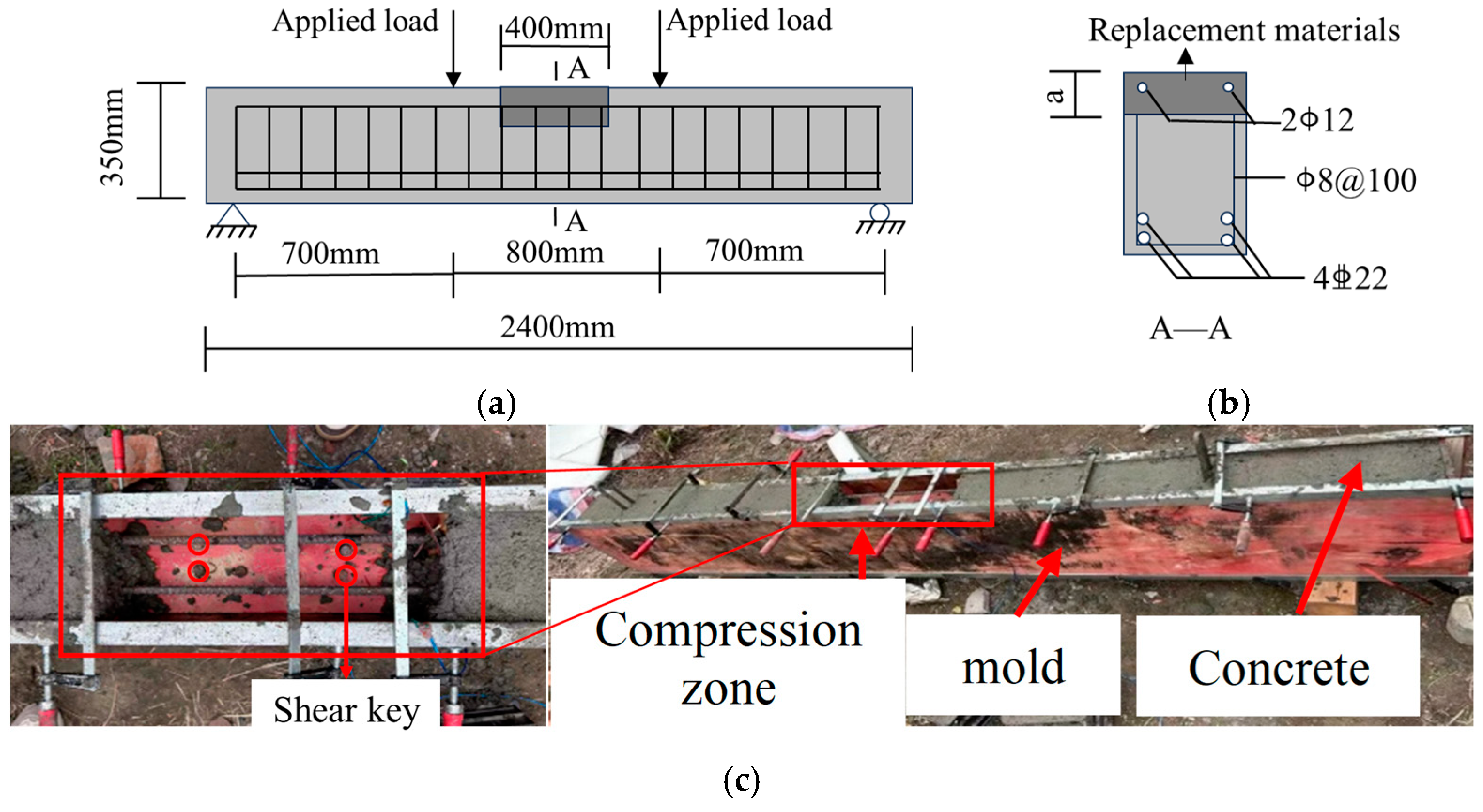
2.2. Preparation of Steel-Reinforced Concrete Beams

Figure 1a shows that the dimensions of the reinforced concrete beam are L × b × h = 2400 mm × 150 mm × 350 mm. The reinforcement details are shown in Figure 1b. The reinforced concrete beam was cast in two stages: first, ordinary concrete was poured, and after initial setting, the SIFCON was poured in the pre-set compression zone. The length of the compression zone with the SIFCON is 400 mm, with heights of 30 mm and 60 mm, as shown in the casting process in Figure 1c. The four shear keys connect the concrete and the materials in the compressed zone, preventing slippage between them. The detailed parameters for the steel-reinforced concrete beams are listed in Table 5.

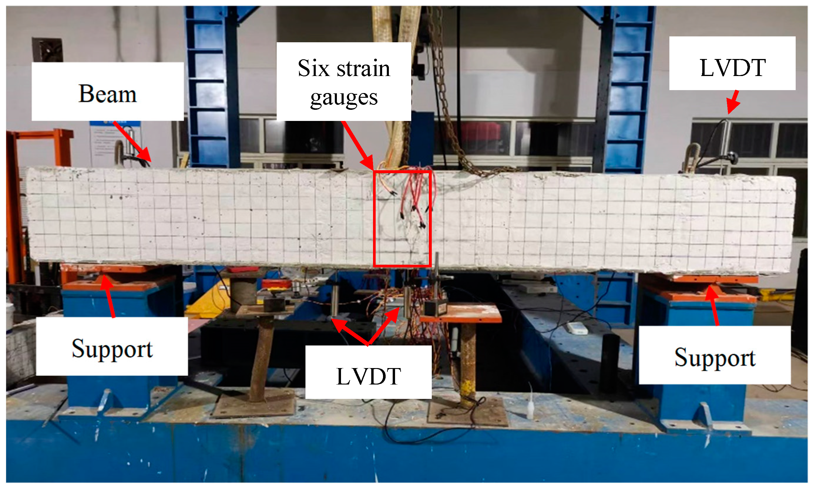
2.3. Four-Point Bending Test

Figure 2 shows the test set-up of the steel-reinforced concrete beam. A four-point bending loading method was used, and the pure bending section was controlled to be 800 mm by a distribution beam. The loading equipment was a 50-ton electro-hydraulic servo testing machine, and the loading was carried out in a displacement-controlled mode at a rate of 2 mm/min until the specimen failed. The displacement measurement points are shown in Figure 2, and the displacement was recorded by using LVDT, which is provided by Beijing Jinghaiquan Sensing Technology Co., Ltd. (Beijing, China). The displacement and load were collected using the Donghua DH3816 dynamic data acquisition system, which is produced by Jiangsu Donghua Testing Technology Co., Ltd. (Taizhou, China).

3. Results and Discussion
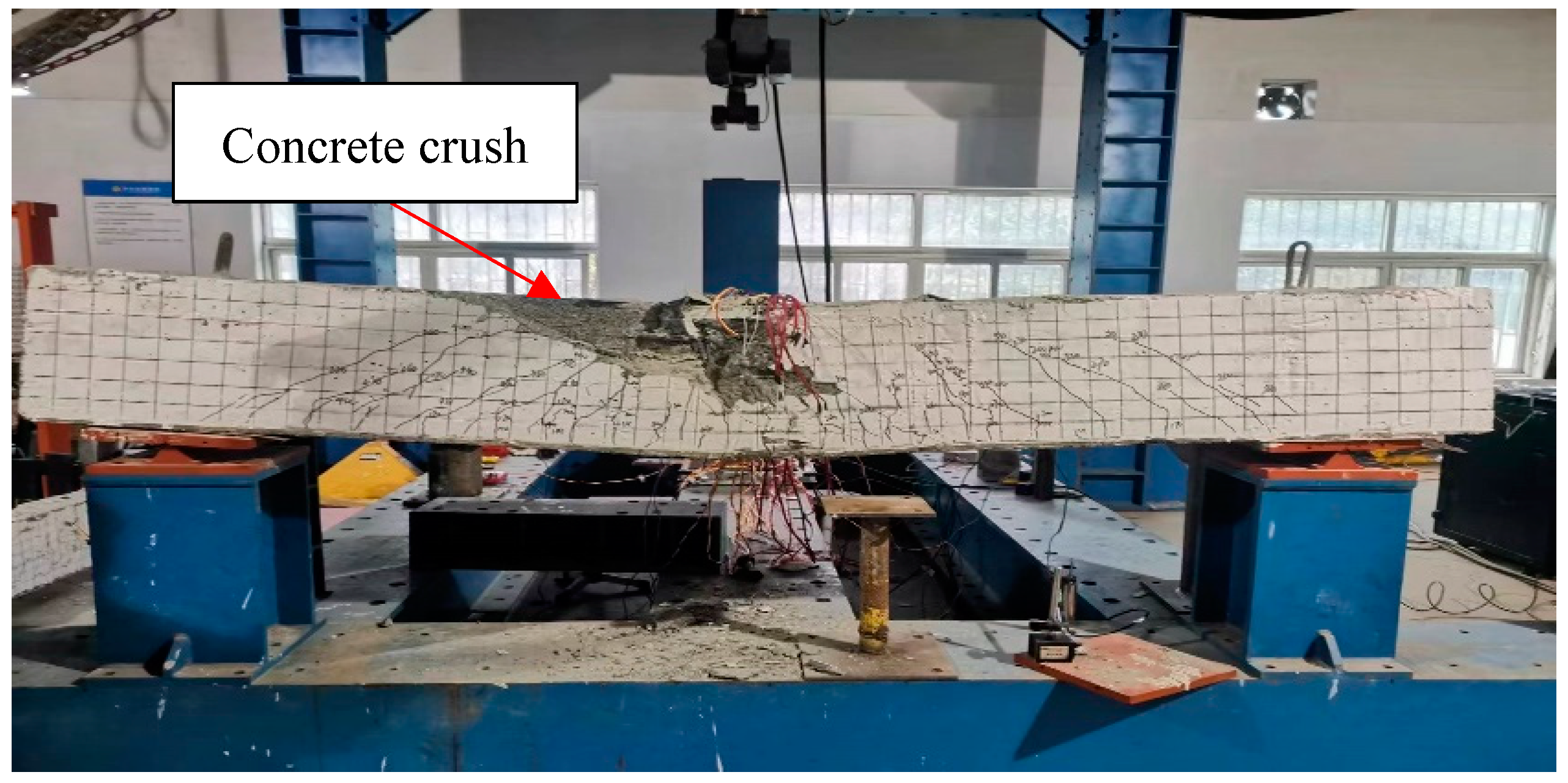
3.1. Failure Mode

Figure 3 shows the failure mode of beam SB-50-30. When the load reaches 110 kN, the first crack appears in the middle of the pure bending region of the concrete beam. As the load increases to 160 kN, the crack begins to shift from the pure bending region toward the supports. With continued loading, new cracks form, and the cracks start to propagate upward, with the crack width increasing. After the load reaches 320 kN, no new cracks are generated, and the existing cracks continue to extend into the compression zone, with the crack width increasing rapidly. Eventually, the concrete at the top of the midspan begins to crush, and pieces of concrete even start to spall. After the load reaches 470 kN, the beam undergoes rapid failure, with a rapid increase in deflection, leading to the failure of the concrete beam. The reinforced concrete beam failed by the SIFCON crush of the compression zone. The failure mode of SB-50-60 is similar to SB-50-30, with all specimens failing due to concrete crushing in the compressed zone. This failure is attributed to the over-reinforced nature of the concrete.

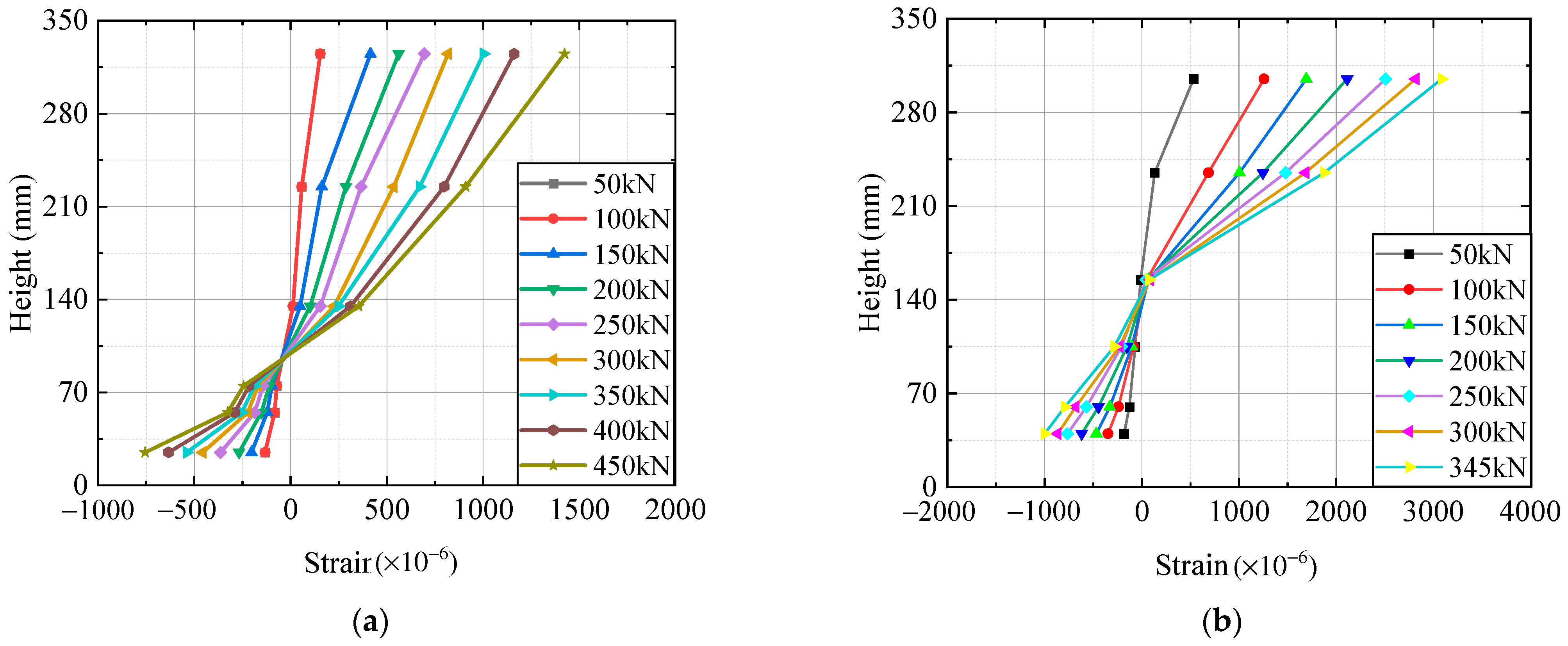
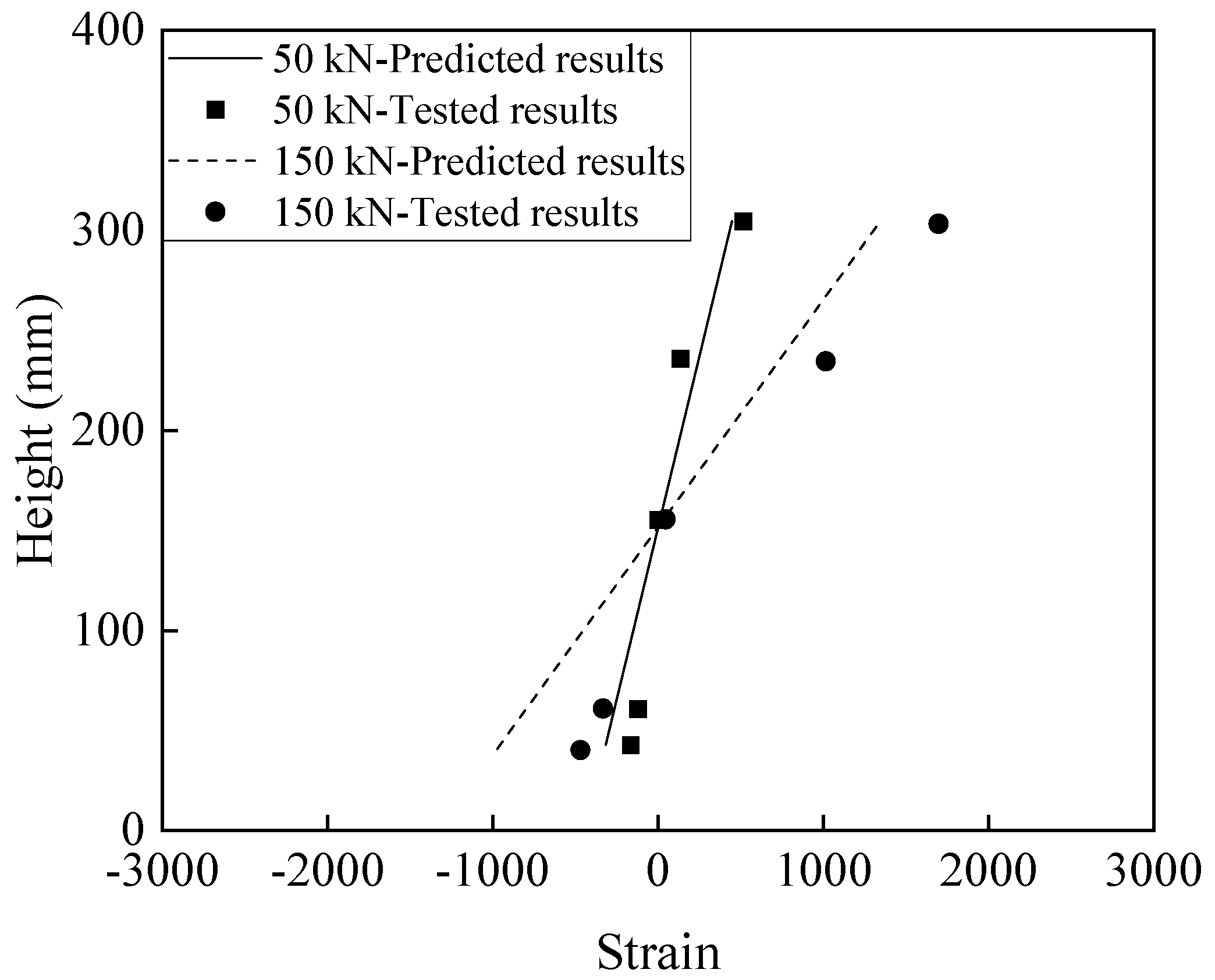
3.2. Cross-Section Strain Distribution

Figure 4 shows the cross-section strain distribution in the test beam. As the load increases, the strain in the tensile side and compressive side of the concrete increases. However, the strain change on the compressive side is larger than that on the tensile side. This is mainly because the compressive deformation capacity of SIFCON in the compressive zone is better than that of ordinary concrete. The change in the height of the neutral axis is relatively small because both SB-50-30 and SB-50-60 are over-reinforced beams, with small strain in the tensile reinforcement. Whether for SB-50-30 or SB-50-60, no slippage occurred between the SIFCON and ordinary concrete in the compressive zone. A shear key was placed between the compressed zone material and the ordinary concrete to prevent relative sliding between the two. The strain distribution of the locally reinforced concrete beam in the compressive zone of SIFCON at mid-span shows a nearly linear relationship with the section height, indicating that the locally reinforced concrete beam in the compressive zone of SIFCON generally conforms to the plane section assumption. A similar finding was reported in Ref. [26]. The cross-section of the RC beams strengthened with materials in the compressed zone remains planar during the loading process.

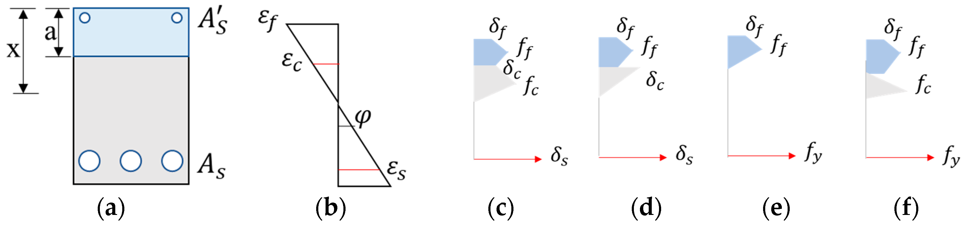
3.3. Theoretical Analysis

Based on the tested results of cross-section strain distribution, it is evident that the strain in the locally reinforced concrete section in the compression zone aligns with the plane section assumption. A finite strip method was employed to evaluate the load-bearing performance of the locally reinforced concrete beams in the compression zone [31]. Depending on the failure mode, the calculation formulas were divided into four cases, as shown in Figure 5. Figure 5a,b show the force condition of the cross-section of a bending member and cross-section strain distribution. Figure 5c shows that the materials in the compressed zone reach the ultimate strain, with the concrete compressing and the longitudinal steel yielding in tension. Figure 5d shows that the materials in the compressed zone reach the ultimate strain, with the concrete remaining elastic and the tensile steel yielding. Figure 5e shows that the materials in the compressed zone reach the ultimate strain, with the concrete remaining elastic, the concrete disengaging, and the tensile steel yielding. Figure 5f shows that the concrete disengages, and both the tensile steel and the materials in the compressed zone reach the yielding strain.
Based on the plane section assumption as shown in Figure 5b, the stress–strain relationships between materials are expressed as follows:
φ = ε f x
x = ε f φ
ε s = h x φ
where x is the depth of the compression zone, mm; ε f is the strain of the replacement materials in the compressed zone; and ε s is the strain of the longitudinal bar. The curvature ( φ ) of a cross-section, also referred to as the section curvature, represents the angle of rotation per unit length of the concrete beam.
Under four-point bending loads, the resultant force of the rebar, concrete, and materials in the compressed zone is zero. The bending moment of the beam section is determined by the moment of the concrete in the compressed zone and the enhanced materials in the compressed zone with respect to the tensile reinforcement. The force equilibrium and moment calculation are given by Equations (4) and (5).
F s = F f + F c
M = M f + M c
The stress distribution across the cross-section was determined by Equations (1)–(3), with the force and moment consisting of the contributions from each strip. The total force and moment are expressed as follows:
F c = i = 1 n δ c , i b h n
F f = i = 1 n δ f , i b h n
M c = i = 1 n δ c , i b h n · x i h 2
M f = i = 1 n δ f , i b h n · x i h 2
Figure 6 shows a comparison of the tested and predicted cross-sectional strain distributions. When the applied load is 50 kN, the strain distribution of SB-50-60 exhibits a linear relationship with height, which closely matches the predicted results. As the applied load reaches the ultimate load capacity, the strain distribution of SB-50-60 remains nearly linear and is still close to the predicted results. This indicates that the finite strip element calculation can predict the behavior of locally reinforced concrete beams in the compressive zone of the SIFCON at mid-span, based on the plane section assumption.
The specimens ρ = 2.46 % & a = 30 mm and ρ = 2.98 % & a = 30 mm were tested as descripted in Ref. [26]. The literature data were adopted for calculations using the proposed equations. Figure 7 compares the results and predictions, showing that the predicted load–mid-span deflection curves closely match the experimental results. The maximum load capacity predictions for the specimens ρ = 2.46 % & a = 30 mm and ρ = 2.98 % & a = 30 mm are 114.7 kN and 133.8 kN, respectively, showing errors of only 11% and 7%, respectively, compared to the tested values. The experimental data show that when the compressed zone enters the yielding stage, the load fluctuates with increasing deflection. This is primarily due to the fluctuations in the height of the compressed zone. This indicates that the proposed finite strip method equations effectively predict the bending performance of steel-reinforced concrete beams strengthened with highly ductile cementitious composites in the compression zone.

3.4. Parametric Analysis

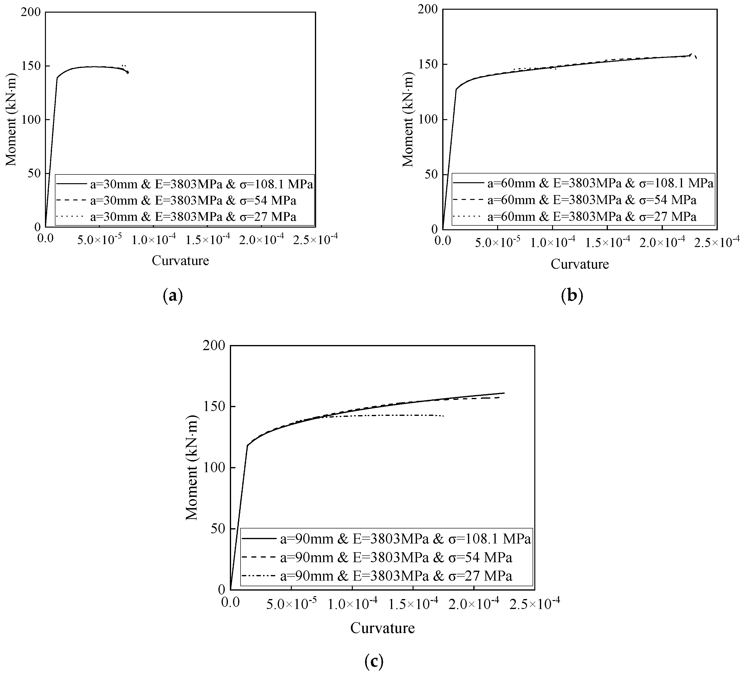
3.4.1. Effects of the Compressive Strength of Materials in the Compressed Zone on the Moment–Curvature Curves

Figure 8 shows the effect of the compressive strength of the materials in the compressed zone on the moment–curvature curves. All curves are divided into two stages. The first stage is the elastic phase, where the moment increases sharply with curvature until the material in the compression zone begins to yield. The second stage is the yield phase, where the moment remains stable as the curvature increases. The secant stiffness of the first stage of the moment–curvature curve was defined as determined by the stiffness of the steel-reinforced beam. Figure 8a shows that at a compression zone height of 30 mm, the compressive strength of the materials in the compressed zone have no impact on the stiffness of the moment–curvature curve due to the small height of the compressed zone. Figure 8b shows that at a height of 60 mm, similar results are observed, with the changes in the compressive strength of the materials in the compressed zone having no effect on the stiffness of the moment–curvature curve. Figure 8c shows that at a height of 90 mm, with the same elastic modulus of the materials in the compressed zone, increasing the material compressive strength in the compressed zone has no effect on the elastic phase but significantly impacts the yield phase. The maximum bending moment and curvature increase with higher compression strength.
Table 6 presents the maximum bending moment and ultimate curvature values. At a compression zone height of 30 mm, the compressive strength of the materials in the compression zone has no impact on the maximum bending moment or ultimate curvature. At a height of 60 mm, increasing the compressive strength of the materials in the compression zone raises the maximum bending moment and curvature. Tripling the compressive strength results in a 20% increase in the maximum bending moment and a 120% increase in ultimate curvature. At a height of 90 mm, tripling the compressive strength of the materials in the compression zone increases the maximum bending moment by 29% and the curvature by 13%. When the compression zone height exceeds 60 mm, enhancing the compressive strength of the materials in the compression zone improves both the load capacity and the deformation ability of the beam.

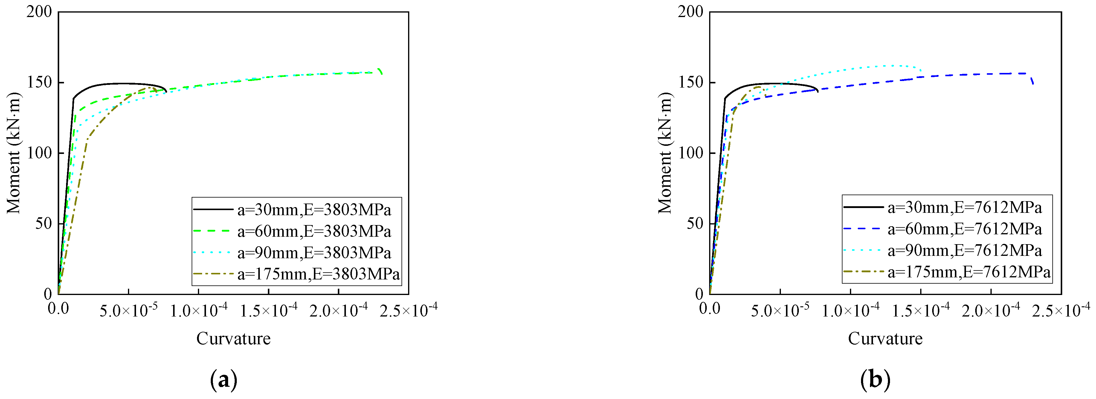
3.4.2. Effects of the Height of the Replacement Material in the Compressed Zone on the Moment–Curvature Curves

Figure 9 illustrates the effects of the height of the replacement material in the compressed zone on the moment–curvature curves. All curves exhibit a two-stage behavior. The impact of the compressed zone height on the moment–curvature curves is significant. As the compressed zone height increases, the initial stiffness rises. The maximum bending moment and ultimate curvature corresponding to these changes are detailed in Table 7.
Table 7 presents the maximum bending moment and ultimate curvature. The height of the replacement material in the compressed zone has a minor effect on the maximum bending moment. When the height increases from 30 mm to 90 mm, with a modulus of elasticity of 3803 MPa, the maximum bending moment changes by only 5%, and with a modulus of 7612 MPa, the change is just 8%. However, the height significantly affects the ultimate curvature. Under the same conditions, the ultimate curvature increases by 192% and 95%, respectively.

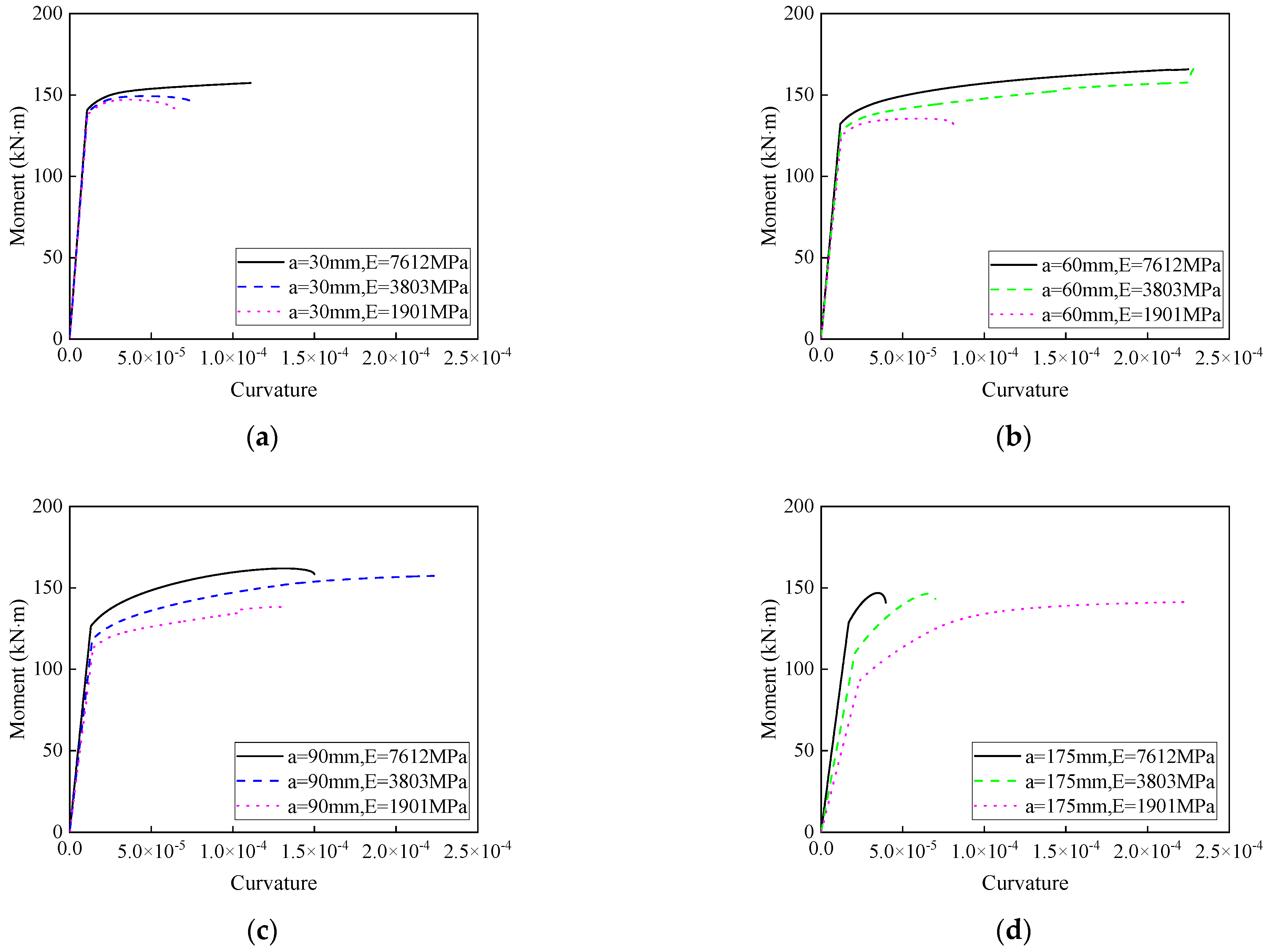
3.4.3. Effects of the Elastic Modulus of the Materials in the Compressed Zone on the Moment–Curvature Curves

Figure 10 illustrates the effects of the elastic modulus of the materials in the compressed zone on the moment–curvature curves. All curves exhibit a two-stage behavior. For a compressed zone height of 30 mm, changes in the initial stiffness of the compressed zone material do not influence the moment–curvature curves, as shown in Figure 10a. For heights of 60 mm, 90 mm, and 175 mm, the initial stiffness of the moment–curvature curves increases with the modulus of the compressed zone material, and the increasing trend becomes more pronounced with greater height. The maximum bending moment and ultimate curvature are detailed in Table 8.
Table 8 presents the maximum bending moment and ultimate curvature. For a compressed zone height of 30 mm, increasing the elastic modulus of the material by 2.5 times results in a 7% increase in the maximum bending moment and a 67% increase in the ultimate curvature. At a height of 60 mm, the increases are 22% and 177%, respectively, while for 90 mm, the increases are 17% and 16%. The elastic modulus of the compressed zone has a greater effect on the ultimate curvature than on the maximum bending moment, with the impact influenced by the compressed zone height. The most significant improvements occur at a height of 60 mm (for a beam height of 350 mm).
The present study aims to investigate the effects of the mechanical properties and height of materials in the compressed zone on the performance of over-reinforced concrete beams. It is worth noting that the calculation formula cannot account for the slippage between the compressed zone materials and the concrete. For practical engineering applications, further research is needed to establish design formulas that can guide strengthening design. Additionally, this study explores the parameters for shear key settings between the compressed zone materials and concrete.

4. Conclusions

This study experimentally investigates the effects of highly ductile cementitious composites in the compression zone on the mechanical behavior of over-reinforced concrete beams. After validating theoretical formulas, a parametric analysis was conducted on the material properties and replacement height of the compression zone. The findings are as follows:
  • Replacing concrete with SIFCON retains the linear strain distribution across the beam height, aligning with the plane section assumption. It was proven that the bending performance can be calculated using the strip method.
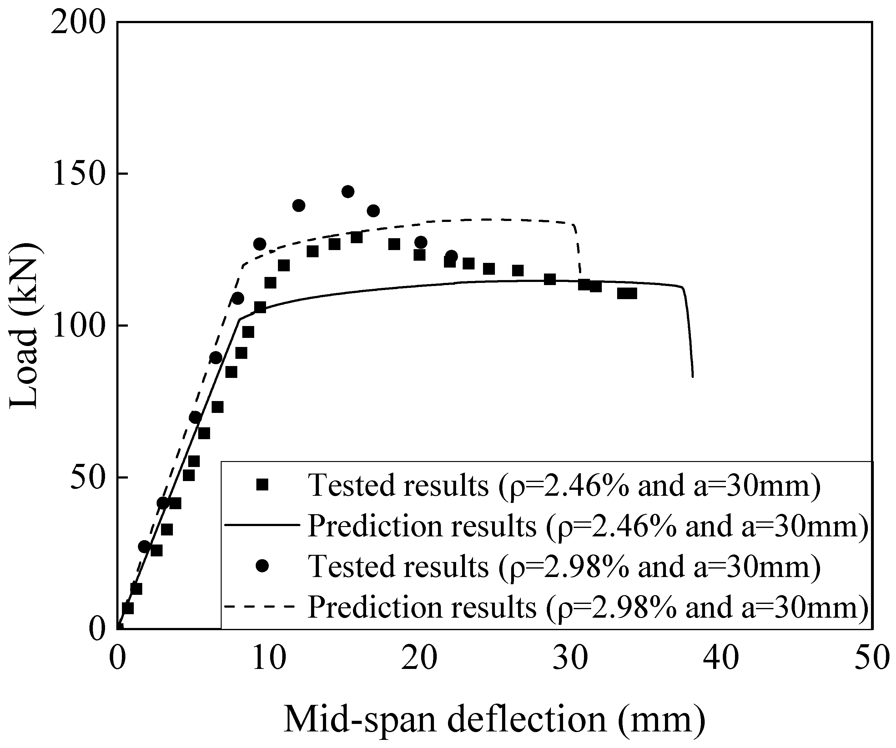
  • The proposed theoretical formulas effectively predict the mechanical performance of beams strengthened with highly ductile cementitious composites. The parametric analysis indicates that the curvature is more sensitive to the material height, modulus, and strength than the maximum moment.
  • The compressive strength of the materials in the compression zone does not affect the initial stiffness of the moment–curvature curves. Increased material height and strength lead to higher maximum moments and ultimate curvatures.
  • Increasing the material’s elastic modulus raises the maximum curvature. At a height of 60 mm, the curvature improves by up to 177%.
  • As the compression zone height increases, the maximum curvature rises. For a material modulus of 3803 MPa, the curvature increases by up to 192%.

Author Contributions

Y.P.: Methodology, Investigation, Writing—Original Draft. J.W. and B.C.: Investigation, Writing—Original Draft, Formal Analysis. Z.M.: Conceptualization, Funding Acquisition, Writing—Reviewing and Editing. C.L.: Writing—Reviewing and Editing. All authors have read and agreed to the published version of the manuscript.

Funding

Financial support for this study was received from the open fund project of the Key Laboratory of Safe Construction and Intelligent Maintenance for Urban Shield Tunnels of Zhejiang Province (Grant No. HZCU-UST-23-05).

Data Availability Statement

All data are available in the main text.

Acknowledgments

The authors would like to acknowledge the financial support of the open fund project of the Key Laboratory of Safe Construction and Intelligent Maintenance for Urban Shield Tunnels of Zhejiang Province (Grant No. HZCU-UST-23-05).

Conflicts of Interest

The authors declare no conflicts of interest.

References

  1. Ding, M.; Xu, W.; Wang, J.; Chen, Y.; Du, X.; Fang, R.; Huang, X.; Sun, H. Plastic hinge regions of prefabricated concrete columns with grouted sleeves and simplified calculation method for plastic hinge length. Structures 2022, 43, 710–725. [Google Scholar] [CrossRef]
  2. Duhaim, H.M.; Mashrei, M.A. The effect of using steel fibers reinforced concrete layer in compression zone on the flexural behavior of over-reinforced concrete beams. Struct. Concr. 2024, 25, 456–472. [Google Scholar] [CrossRef]
  3. Lu, Z.; Su, L.; Xian, G.; Lu, B.; Xie, J. Durability study of concrete-covered basalt fiber-reinforced polymer (BFRP) bars in marine environment. Compos. Struct. 2020, 234, 111650. [Google Scholar] [CrossRef]
  4. Xian, G.; Zhou, P.; Li, C.; Dong, S.; Du, H.; Tian, J.; Guo, R.; Peng, Z.; Zhang, Z.; He, T. Mechanical properties evaluation of glass fiber reinforced thermoplastic composite plate under combined bending loading and water immersion. Constr. Build. Mater. 2024, 440, 137470. [Google Scholar] [CrossRef]
  5. Wu, G.; Wang, X.; Wu, Z.; Dong, Z.; Zhang, G. Durability of basalt fibers and composites in corrosive environments. J. Compos. Mater. 2015, 49, 873–887. [Google Scholar] [CrossRef]
  6. Wu, Y.F. Ductility demand of compression yielding fiberreinforced polymer-reinforced concrete beams. ACI Struct. J. 2008, 105, 104. [Google Scholar]
  7. Wang, B.; Cui, C.; Xu, C.; Meng, K.; Li, J.; Xu, L. A novel analytical solution for horizontal vibration of partially embedded offshore piles considering the distribution effect of wave loads. Ocean Eng. 2024, 307, 118179. [Google Scholar] [CrossRef]
  8. Wu, Y.-F.; Zhou, Y.-W.; He, X.-Q. Performance-based optimal design of compression-yielding FRP-reinforced concrete beams. Compos. Struct. 2010, 93, 113–123. [Google Scholar] [CrossRef]
  9. Shi, J.; Qin, T.; Zhou, J.; Zhao, H.; Wang, H.; Fu, J.; Jin, L. Interlaminar shear behavior of basalt fiber-reinforced polymer tendons subjected to a combined effect of prestress, grout and seawater. Constr. Build. Mater. 2025, 462, 139982. [Google Scholar] [CrossRef]
  10. Shoji, D.; He, Z.; Zhang, D.; Li, V.C. The greening of engineered cementitious composites (ECC): A review. Constr. Build. Mater. 2022, 327, 126701. [Google Scholar] [CrossRef]
  11. Shafighfard, T.; Kazemi, F.; Asgarkhani, N.; Yoo, D.-Y. Machine-learning methods for estimating compressive strength of high-performance alkali-activated concrete. Eng. Appl. Artif. Intell. 2024, 136, 109053. [Google Scholar] [CrossRef]
  12. Xue, J.; Mao, S.; Cacciola, P.; Contento, A.; Lampropoulos, A.; Nicolaides, D.; Petrou, M.F.; Yang, Z.; Briseghella, B. Experimental evaluation of the effectiveness of fiber orientation methods on the mechanical performance of UHPFRC. Constr. Build. Mater. 2024, 448, 138184. [Google Scholar] [CrossRef]
  13. Curosu, I.; Mechtcherine, V.; Forni, D.; Cadoni, E. Performance of various strain-hardening cement-based composites (SHCC) subject to uniaxial impact tensile loading. Cem. Concr. Res. 2017, 102, 16–28. [Google Scholar] [CrossRef]
  14. Ma, Z.; Zhang, Z.; Liu, X.; Zhang, Y.; Wang, C. Reusing waste glass fines to substitute cement and sand for recycled ultra-high performance strain-hardening cementitious composites (UHP-SHCC). Constr. Build. Mater. 2024, 455, 139186. [Google Scholar] [CrossRef]
  15. Kobayashi, K.; Le Ahn, D.; Rokugo, K. Effects of crack properties and water-cement ratio on the chloride proofing performance of cracked SHCC suffering from chloride attack. Cem. Concr. Compos. 2016, 69, 18–27. [Google Scholar] [CrossRef]
  16. Ali, M.H.; Atiş, C.D.; Al-Kamaki, Y.S.S. Mechanical properties and efficiency of SIFCON samples at elevated temperature cured with standard and accelerated method. Case Stud. Constr. Mater. 2022, 17, e01281. [Google Scholar] [CrossRef]
  17. Liu, F.; Li, Y.; Lv, J.; Liu, Y.; Li, H.; Mu, F. Uniaxial compression performance of SIFCON with the arc-shaped steel fibers. J. Build. Eng. 2025, 100, 111678. [Google Scholar] [CrossRef]
  18. Ding, Y.; Yu J-t Yu, K.-Q.; Xu, S.-l. Basic mechanical properties of ultra-high ductility cementitious composites: From 40 MPa to 120 MPa. Compos. Struct. 2018, 185, 634–645. [Google Scholar] [CrossRef]
  19. Yu, K.-Q.; Yu, J.-T.; Dai, J.-G.; Lu, Z.-D.; Shah, S.P. Development of ultra-high performance engineered cementitious composites using polyethylene (PE) fibers. Constr. Build. Mater. 2019, 216, 698. [Google Scholar] [CrossRef]
  20. Wu, Z.; Shi, C.; He, W.; Wang, D. Uniaxial compression behavior of ultra-high performance concrete with hybrid steel fiber. J. Mater. Civ. Eng. 2016, 28, 06016017. [Google Scholar] [CrossRef]
  21. Feng, L.; Wu, Y.-F.; Guo, B.-C.; Huang, X.-X. Reducing target reliability index of concrete bridge beams through compression yielding. Eng. Struct. 2024, 316, 118506. [Google Scholar] [CrossRef]
  22. Ziara, M.M.; Haldane, D.; Kuttab, A.S. Flexural behavior of beams with confinement. ACI Struct. J. 1995, 92, 103–114. [Google Scholar]
  23. Yuan, F.; Pan, J.; Leung, C.K.Y. Flexural behaviors of ECC and concrete/ECC composite beams reinforced with basalt fiber-reinforced polymer. J. Compos. Constr. 2013, 17, 591–602. [Google Scholar] [CrossRef]
  24. Atta, A.M.; Khalil, A.E.-H. Improving the failure mode of over-reinforced concrete beams using strain-hardening cementitious composites. J. Perform. Constr. Facil. 2016, 30, 04016003. [Google Scholar] [CrossRef]
  25. Shen, X.; Li, B.; Shi, W.; Chen, Y.-T. Numerical study on flexural behaviour of FRP reinforced concrete beams with compression yielding blocks. Case Stud. Constr. Mater. 2022, 17, e01169. [Google Scholar] [CrossRef]
  26. Deng, M.; Zhang, M.; Zhu, Z.; Ma, F. Deformation capacity of over-reinforced concrete beams strengthened with highly ductile fiber-reinforced concrete. Structures 2021, 29, 1861–1873. [Google Scholar] [CrossRef]
  27. Balaji, S.; Thirugnanam, G. Behaviour of reinforced concrete beams with SIFCON at various locations in the beam. KSCE J. Civ. Eng. 2018, 22, 161–166. [Google Scholar] [CrossRef]
  28. Li, H.; Li, Y.; Pan, Y.; Ng, P.L.; Leung, C.K.Y.; Zhao, X. Compressive properties of a novel slurry-infiltrated fiber concrete reinforced with arc-shaped steel fibers. J. Zhejiang Univ.-Sci. A 2023, 24, 543–556. [Google Scholar] [CrossRef]
  29. GB/T 50010-2010; Code for Design of Concrete Structures. China Standard Publishing House: Beijing, China, 2010.
  30. GB/T 28900-2022; Test Methods of Steel for Reinforcement of Concrete. State Administration for Market Regulation: Beijing, China, 2022.
  31. Su, M.; Gong, S.; Liu, Y.; Peng, H. Flexural behavior of RC beams strengthened with fully or partially prestressed near-surface mounted FRP strips: An experimental investigation. Eng. Struct. 2022, 262, 114345. [Google Scholar] [CrossRef]
Figure 1. Preparation of steel-reinforced concrete beam: (a) dimensions, (b) detailed reinforcement, and (c) casting process.
Buildings 15 00510 g001
Figure 2. Test set-up of the reinforced concrete beam.
Buildings 15 00510 g002
Figure 3. Failure mode of SB-50-30.
Buildings 15 00510 g003
Figure 4. Cross-section strain distribution of (a) SB-50-30 and (b) SB-50-60.
Buildings 15 00510 g004
Figure 5. The stress–strain relationship of the concrete beam cross-section: (a) force condition of the cross-section of a bending member, (b) strain distribution, (c) Case I, (d) Case II, (e) Case III, and (f) Case IV.
Buildings 15 00510 g005
Figure 6. Comparisons of tested and predicted cross-sectional strain distributions.
Buildings 15 00510 g006
Figure 7. Verification of the actual and predicted results.
Buildings 15 00510 g007
Figure 8. Effects of the compressive strength of the compressed zone on the moment–curvature relationship: (a) 30 mm height, (b) 60 mm height, and (c) 90 mm height.
Buildings 15 00510 g008
Figure 9. The effects of the height of the replacement material of an (a) elastic modulus of 7612 MPa and an (b) elastic modulus of 3803 MPa in the compressed zone on the moment–curvature curves.
Buildings 15 00510 g009
Figure 10. The effects of the elastic modulus of the compressed zone on the moment–curvature curves: (a) 30 mm height, (b) 60 mm height, (c) 90 mm height, and (d) 175 mm height.
Buildings 15 00510 g010
Table 1. Concrete mix ratio (per cubic meter of concrete) and compressive strength.
GradeWater (kg/m3)Cement (kg/m3)Coarse Aggregate (kg/m3)Fine Aggregate (kg/m3)28-Day
Compressive Strength (MPa)
C50205488119556254.7
Table 2. Mix proportion of SIFCON matrix (Unit: kg/m3).
GradeWaterCementFly AshSilica FumeFine SandSuperplasticizerSteel Fibers (%)
C40274593274469134.96.8
Table 3. Performance parameters of hooked-end steel fibers.
TypeLength (mm)Diameter (mm)Aspect RatioTensile Strength (MPa)Density (kg/m3)
Hooked-end steel fibers30.00.506011007800
Table 4. Mechanical properties of steel reinforcement.
TypeDiameter (mm)Elastic Modulus (GPa)Yielding Strength (MPa)Ultimate Strength (MPa)Elongation at Break (%)
HRB3001021043051816
HRB4002220045658824
Table 5. Detailed parameters of the reinforced concrete beam.
SpecimensCompression Zone Height (mm)SIFCON Compressive Strength (MPa)Ratio of Reinforcement (%)
SB-50-3030503.37
SB-50-6060503.37
Table 6. Effects of compressive strength on maximum bending moment and ultimate curvature.
Height (mm)Compressive Strength (MPa)Maximum Bending Moment (kN·m)Ultimate Curvature (×10−4)
30108149.20.76
54149.30.77
27151.20.75
60108175.72.3
54159.92.3
27146.61.1
90108161.12.3
54157.42.3
27143.01.8
Table 7. Effects of the height of the replacement on maximum bending moment and ultimate curvature.
Elastic Modulus (MPa)Height (mm)Maximum Bending Moment (kN·m)Ultimate Curvature (×10−4)
380330149.20.8
60159.92.3
90157.42.2
175146.40.7
761230149.20.8
60156.62.3
90161.91.5
175146.90.5
Table 8. Effects of the elastic modulus of the materials on the maximum bending moment and ultimate curvature.
Height (mm)Elastic Modulus (MPa)Maximum Bending Moment (kN·m)Ultimate Curvature (×10−4)
307612157.41.1
3803149.30.8
1901147.10.7
607612165.80.2
3803167.30.2
1901135.50.8
907612161.91.5
3803157.42.2
1901138.31.3
1757612146.90.4
3803146.40.7
1901141.80.2
Disclaimer/Publisher’s Note: The statements, opinions and data contained in all publications are solely those of the individual author(s) and contributor(s) and not of MDPI and/or the editor(s). MDPI and/or the editor(s) disclaim responsibility for any injury to people or property resulting from any ideas, methods, instructions or products referred to in the content.

