Article

Investigation on Buckling Behaviour of Scaffold Independent Supporting System Considering Semi-Rigid Nodes

1
State Key Laboratory of Coastal and Offshore Engineering, Dalian University of Technology, Dalian 116024, China
2
China MCC5 Group Corp., Ltd., Chengdu 610063, China
3
School of Computing, Engineering and Built Environment, Glasgow Caledonian University, Glasgow G4 0BA, Scotland, UK
*
Authors to whom correspondence should be addressed.
Buildings 2025, 15(3), 443; https://doi.org/10.3390/buildings15030443
Submission received: 19 December 2024 / Revised: 24 January 2025 / Accepted: 27 January 2025 / Published: 30 January 2025
(This article belongs to the Section Building Structures)

Abstract

This study investigated the buckling behaviour of the scaffold independent supporting system considering semi-rigid nodes. Firstly, a scaffold independent supporting system without the horizontal and diagonal braces in the middle or/and bottom parts of the columns was proposed. The scaffold independent supporting system consisted of horizontal beams located under concrete formwork, upright columns, and beam–column nodes. There was a lot of free space within the scaffold independent supporting system, which made it possible to conduct other operational work during the curing of concrete. Then, using numerical simulation, the rotation stiffness of the beam–column node was calculated as 37.18 kN·m/rad. According to the normalized moment–rotation curve, the beam–column node was assessed as a semi-rigid node. Finally, a numerical simulation method was proposed to analyse the buckling behaviour and determine the effective length factor of the scaffold independent supporting system, in which the semi-rigid connection was characterized by setting the spring elements on the beam–column node. The results indicate that the column space and column height have effects on the effective length factor of the scaffold independent supporting system. The effective length factor increased with the increase in the column space, whereas it decreased with the increase in the column height. In addition, the initial imperfection had no obvious effects on the effective length factor.

1. Introduction

In construction processes, the scaffold structure, as a temporary system, plays important roles in supporting concrete formworks and providing working platforms for construction workers. In practical engineering, the failure of the scaffold structures usually occurs due to incompact connections between intersecting bars or successive collapses induced by the local buckling. The failure of the scaffold structure would cause the collapse of the freshly poured concrete elements, which would result in enormous economic loss and significantly threaten personal safety. To ensure the stability of cast-in-place concrete structures during the construction process, it was important to investigate the mechanical response and failure mode of the scaffold supporting system.
In the past few years, many kinds of scaffold supporting systems have been proposed by researchers. At present, three scaffold supporting systems have been widely adopted in practical engineering, i.e., a fastener scaffold, a bowl-hook scaffold and a disc buckle scaffold. Much attention has been paid to the influencing factors on the buckling behaviours of scaffold supporting systems, such as material properties [1,2], initial defects [3,4], support systems [5,6,7], construction phases [8], etc. In addition, numerical simulation methods have been proposed to calculate the buckling loads of the scaffold supporting systems for node stiffness [9,10,11]. For the three scaffold supporting systems, many horizontal and diagonal braces were set in the middle or/and bottom parts of the columns to form a highly interconnected structure. It is worthwhile to point out that there existed no capacious spaces in the existing scaffold supporting system, which made it difficult to conduct other operational work during the curing of concrete. Moreover, the horizontal and diagonal braces consumed many member bars and formed numerous connection nodes, which would enhance the construction cost and increase the operation difficulty. It was necessary to propose a kind of scaffold independent supporting system without the horizontal and diagonal braces in the middle or/and bottom parts of the columns. Nevertheless, when the supporting effects from the horizontal and diagonal braces vanished, the effective length of the compression column increased largely and the load-bearing capacity against buckling failure would decrease significantly. For this reason, the accurate buckling analysis was one of the most important links for the scaffold independent supporting system.
Based on the pressure bar stability theory, the load-bearing capacity with respect to buckling failure is closely associated with geometric configurations, material properties, and boundary conditions [12,13,14]. Typically, geometric configurations and material properties can be precisely determined. However, boundary conditions are often approximated. For instance, in traditional steel-structure design, beam–column connection nodes are commonly considered as either rigid or hinged nodes [15]. In reality, the research conducted by Bjorhovde [16] and Jones [17] has demonstrated that the majority of beam–column connection nodes in steel frames are semi-rigid. The assumption of rigid or hinged nodes may either overestimate or underestimate the actual restraint effect, thereby resulting in an inaccurate evaluation of the buckling load. Regarding the scaffold supporting system, numerous researchers have explored the structural mechanical responses while taking semi-rigid nodes into account [12,18,19,20,21]. It has been observed that the adoption of semi-rigid nodes leads to variations in stress and displacement distributions. Moreover, to describe the stiffnesses of semi-rigid nodes, various mathematical models have been put forward. Examples include the three-parameter exponential mathematical model for the moment–rotation relationship proposed by Chenaghlou [22] and the two-stage, four-parameter moment–rotation curve proposed by Zheng et al. [11]. Li et al. [23] conducted valuable investigations on the load-carrying capacity of the column under axial compression, in which the continuous strength method (CSM) was introduced to predict the load-carrying capacities of the aluminium alloy columns. It was demonstrated that the CSM is more accurate for the load-carrying capacity prediction of H-sectional aluminium alloy stocky columns than other methods. In addition, a section-limiting stress that considers the influence of cross-section slenderness on the load-carrying capacity based on the CSM was introduced for the first time in the design of axially compressed H-section aluminium alloy slender columns [24]. In addition, Li and co-workers [25] proposed a design method using strengthen elitist genetic algorithm (SEGA). SEGA achieved single-parameter optimization for PSSCs, showing high precision and efficiency. However, single-parameter optimization may lead to unstable results or reaching maximum values. It was concluded that incorporating constraints in the optimization process was necessary for multi-parameter constrained optimization to meet practical engineering needs. The existing models for the semi-rigid node provided an effective method to analyse the mechanical response and buckling failure of the scaffold supporting system. Nevertheless, as for a certain beam–column node, it would be more accurate to calculate its actual rotation stiffness using experimental or numerical methods under the real node geometries and boundary conditions.
In addition, determination of the buckling load was important in structure stability analyses. Euler’s formula was an effective approach to calculate the buckling load of the column under compression. The effective length factor was a key parameter in Euler’s formula, and reflected the effect of boundary conditions on the buckling behaviour. Once the effective length factor was determined, the critical buckling load of a single compressive bar can be calculated using Euler’s formula. Thus, the effective length factor is an important parameter to determine the buckling load and analyse the stability of the scaffold independent supporting system. In line with this, this study aimed to investigate the buckling behaviour of the scaffold independent supporting system considering semi-rigid nodes. Firstly, a scaffold independent supporting system without the horizontal and diagonal braces in the middle or/and bottom parts of the columns was proposed and described in detail. Then, numerical simulations were performed to calculate the rotation stiffness of the beam–column node, and the rigidness of the beam–column node was assessed using the normalized moment–rotation curve. Finally, numerical simulations were performed to analyse the buckling behaviours and determine the effective length factors of the scaffold independent supporting systems under different conditions. Based on the numerical results, the effects of the column space, layer height, and initial imperfection on the buckling load and effective length factor were explored.

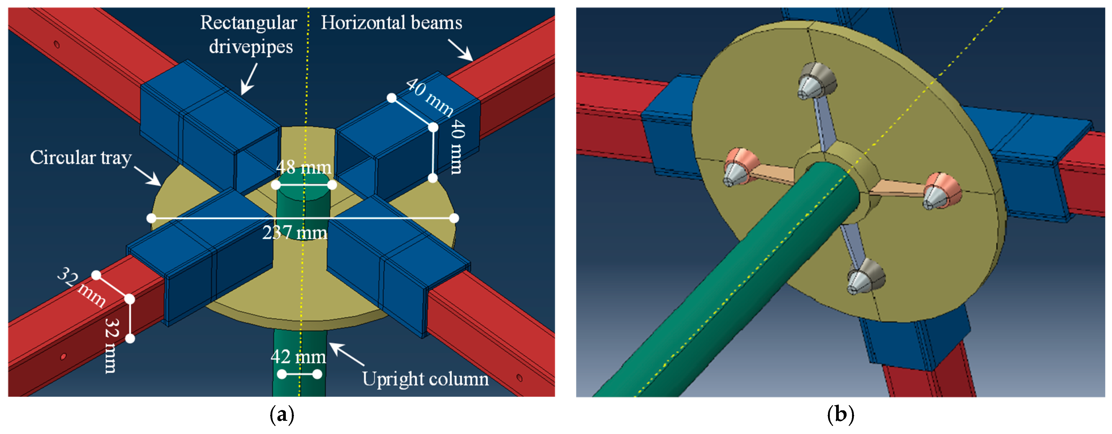
2. Description of the Scaffold Independent Supporting System

A scaffold independent supporting system without horizontal and diagonal braces was proposed in this study, as shown in Figure 1a. The scaffold independent supporting system consisted of horizontal beams located under concrete formwork, upright columns with free height adjustment, and beam–column nodes. From the view of load transfer, the self-gravity of the upper structure was directly supported by the horizontal beams, and then transferred to the upright columns through the beam–column nodes. Meanwhile, the tops of upright columns were connected by the horizontal beams to form a highly interconnected structure. It is worthwhile pointing out that no horizontal and diagonal braces were set at the bottoms of the upright columns. In this way, there existed a lot of free space within the scaffold independent supporting system, which made it possible to conduct other operational work during the curing of concrete.
The beam–column node was a key component in the scaffold independent supporting system, and the internal node, as a typical representative, was investigated in this study, as shown in Figure 1b. It can be seen from the figure that the beam–column node consisted of a circular tray with a circular hole at the centre and four conical holes evenly distributed at 90 degrees, a fastening bolt under the circular tray, and four rectangular drivepipes with conical bars. The beam–column node was assembled following these steps. Firstly, the circular tray was inserted by the upright column along the circular hole, and the position of the circular tray could be adjusted by turning the fastening bolt. Then, four rectangular drivepipes with conical bars were fixed on the circular tray through the conical holes. Finally, two ends of a horizontal beam were set into two rectangular drivepipes affiliated to two adjacent upright columns. In addition, by installing several blocks on the horizontal beam, the top surface of the horizontal beams was adjusted to be abreast with those of the rectangular drivepipes and upright column. In this way, the self-gravity of the upper structure can be supported synchronously by the scaffold independent supporting system.

3. Analysis on the Rigidness of the Beam–Column Node

In this section, the rigidness of the beam–column node in the scaffold independent supporting system was analysed. Firstly, numerical simulations using finite element software ABAQUS (v2022) were conducted to determine the rotation stiffness of the beam–column node. Then, the rigidness of the beam–column node was assessed by the normalized moment–rotation curve. Finally, the type of beam–column node, i.e., rigid node, semi-rigid node, or hinged node, in the scaffold independent supporting system was determined.

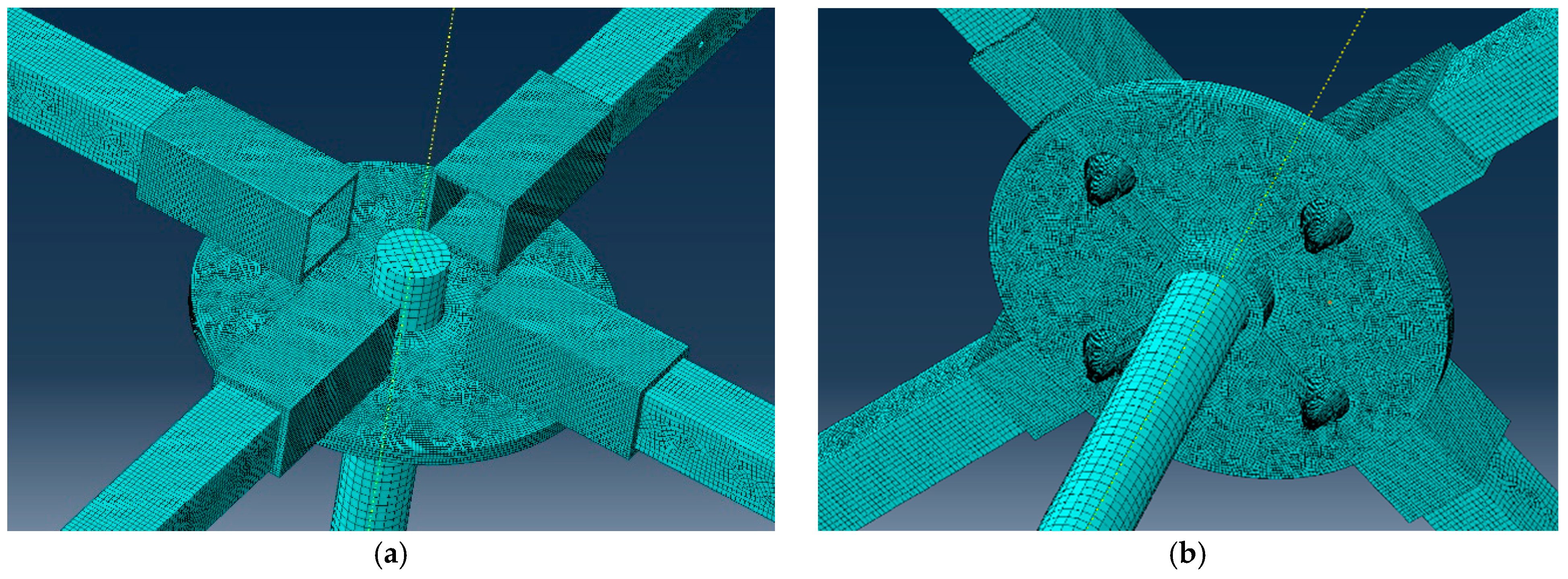
3.1. Three-Dimensional Finite Element Modeling of the Beam–Column Node

In numerical modelling, the beam–column node was reasonably simplified by applying the appropriate constraints. The fastening bolt on the upright column was neglected by setting the binding constraints between the circular tray and upright column. The three-dimensional model of the beam–column node after simplification is shown in Figure 2. The geometric sizes of individual components for the three-dimensional beam–column node model are marked in Figure 2a. For the circular tray, the diameter and thickness were 237 mm and 10 mm, respectively, and the diameter of the circular hole was 48 mm. For the rectangular drivepipes, the width, height and thickness were 40 mm, 40 mm and 4 mm, respectively. For the horizontal beams, the length, width and height were 1217 mm, 32 mm and 32 mm, and the thickness was 4 mm. For the upright column, the outer and inner diameters were 48 mm and 42 mm, respectively, and the length of the upright column was 3190 mm.
Three-dimensional solid element C3D8R was adopted, and it endowed the material parameters of the Q335 steel, i.e., elastic modulus E = 210 GPa and Poisson’s ratio v = 0.3. According to the actual geometric dimensions of individual components, the three-dimensional finite element model was assembled together and meshed reasonably. For the upright column and horizontal beams, the models were meshed in a moderate density, and the maximum element size was 10.5 mm. For the circular tray and rectangular drivepipes, the models were meshed densely, and the maximum element size was 4.8 mm. A three-dimensional finite element model of the beam–column node after reasonable meshing is shown in Figure 3.
As mentioned above, the binding constraints were set between the circular tray and upright column to simulate the effect of the fastening bolt. The displacements of the bottom of the upright column were totally restrained in three directions. In addition, contact elements were set on the contact surfaces between the circular tray and the drivepipes to avoid embedding, and the contact elements with the friction coefficient of 0.8 were set on the friction surfaces between drivepipes and horizontal beams to reflect the friction effect. The displacement restraints and the contact elements applied in the three-dimensional model of the beam–column node are shown in Figure 4.

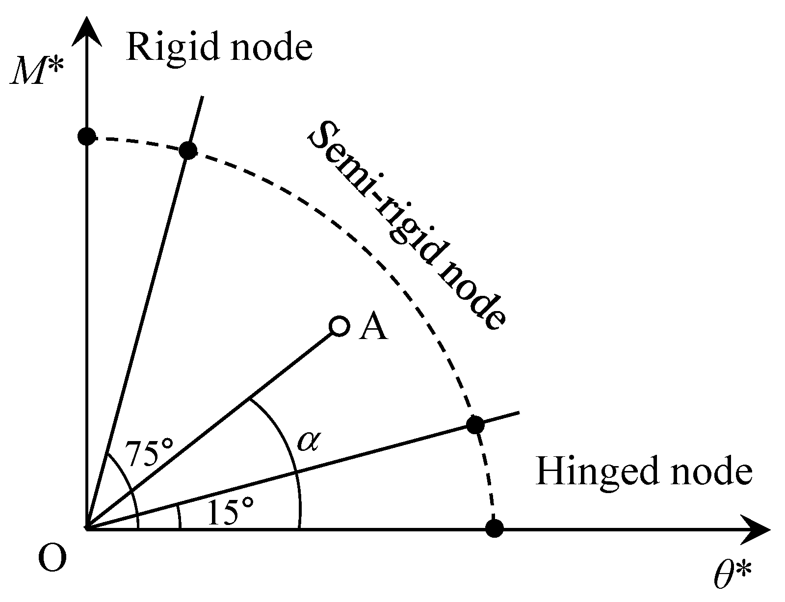
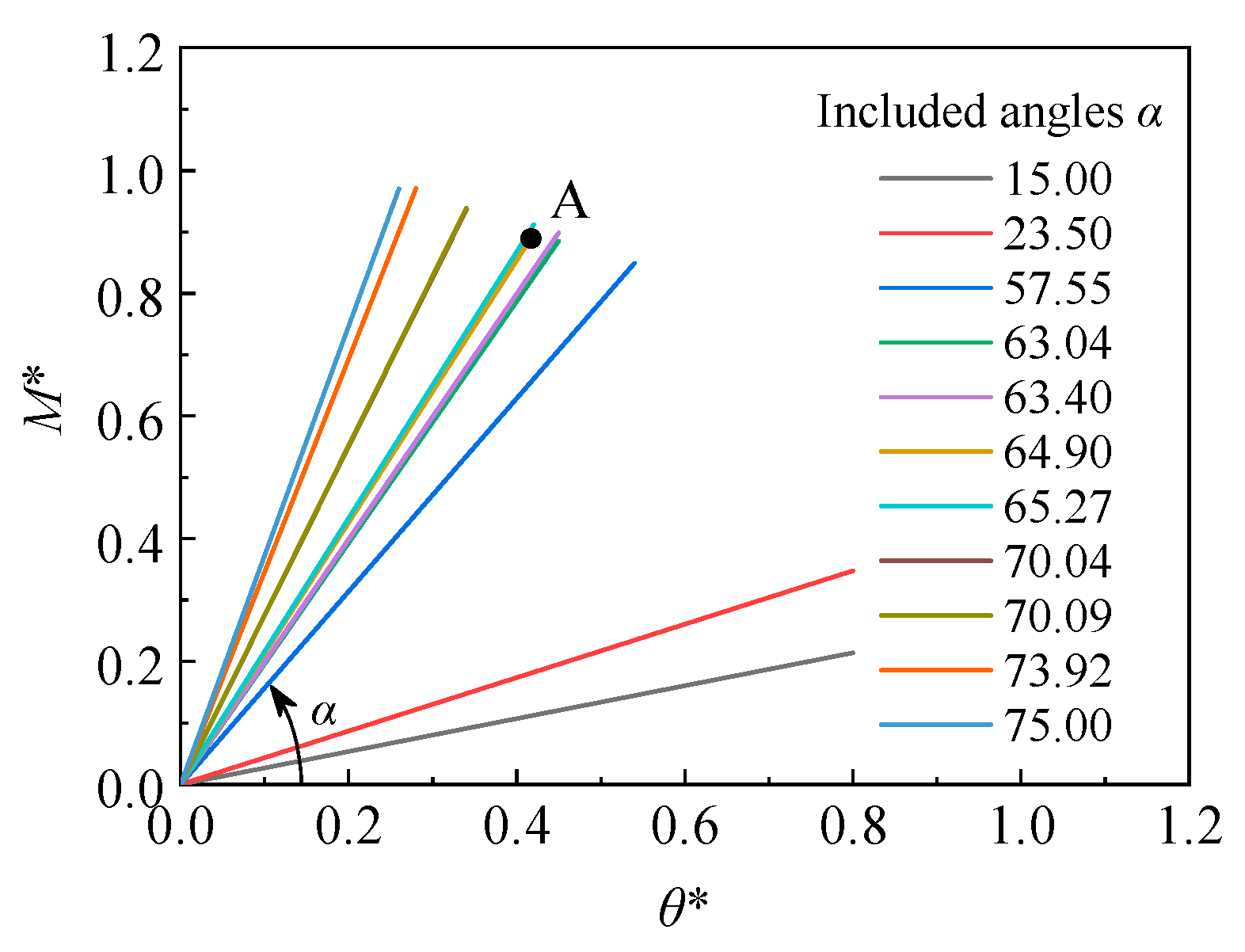
3.2. Assessing the Rigidness of the Beam–Column Node

To calculate the rotation stiffness of the beam–column node, four concentrated forces of 150 N were applied vertically at the ends of four horizontal beams. Numerical simulation was performed to determine the mechanical response of the beam–column node under the four concentrated forces, as shown in Figure 5. The vertical displacement of the loading point was extracted from the numerical results, i.e., 7.68 mm. The bending moment M at the beam–column node can be determined as the product of the concentrated force and arm length, i.e., M = 150 N × 1.38 m = 207 N∙m. The rotation angel θ of the beam–column node can be determined as the quotient of the vertical displacement of the loading point divided by the beam length, i.e., θ = 7.68 mm/1.38 m = 0.0056 rad. In this way, the rotation stiffness of the beam–column node can be determined as the quotient of the bending moment M divided by the rotation angel θ, and was calculated as 207 N∙m/0.0056 rad = 37.18 kN·m/rad.
According to Eurocode 3 Part 1–8, the rigidness of the beam–column node can be assessed by the bending moment vs. rotation angle curve after normalization, denoted as M* − θ* curve, as shown in Figure 6. It can be seen from the figure that the first quadrant of the M* − θ* coordinate system was divided into three regions by two lines with the angles of 15° and 75° from the abscissa axis, namely Regions I, II, and III, which represented the hinged node, semi-rigid node, and rigid node, respectively. Assuming that the (M*, θ*) point of the certain node was Point A in Figure 6, the included angle between the Line OA and abscissa axis was denoted as α. The rigidness of the node can be assessed as follows: (1) if 0° ≤ α ≤ 15°, the node can be regarded as the hinged node; (2) if 15° < α ≤ 75°, the node can be regarded as the semi-rigid node; (3) if 75° < α ≤ 90°, the node can be regarded as the rigid node.
The normalization methods of the bending moment M and rotation angle θ are described here. The bending moment after normalization M* was calculated in Equation (1) as:
M * = M / M p
where Mp is the full plastic bending moment of the beam and was calculated in Equation (2) as:
M p = W p σ s
where Wp is the plastic section modulus of the beam and σs is the yield strength. For the Q335 steel, the yield strength σs was 335 MPa. For the rectangular beam with hollow interior, the plastic section modulus Wp was calculated in Equation (3) as:
W p = b h 2 4 ( b t ) ( h 2 t ) 2 4
where b, h and t are the width, height and thickness of the rectangular beam. The rotation angle after normalization θ* was calculated in Equation (4) as:
θ * = θ S / M p
where S is the linear stiffness of the beam and was calculated in Equation (5) as:
S = E I b / L b
where Ib and Lb are the section inertia moment and the length of the beam, respectively. For the rectangular beam with a hollow interior, the section inertia moment I was calculated in Equation (6) as:
I b = b h 3 ( b t ) ( h 2 t ) 3 12
By substituting the bending moment M, the yield strength σs, and other geometric parameters into Equations (1)–(3), the bending moment after normalization M* was determined. By substituting the rotation angle θ, the elastic modulus E, and other geometric parameters into Equations (4)–(6), the rotation angle after normalization θ* was determined. Finally, the point (M*, θ*) was marked as Point A in the M* − θ* rectangular coordinate system, as shown in Figure 7. The included angle α between Line OA and the abscissa axis was calculated as 64.9°, indicating that the beam-–column nodes in the scaffold independent supporting system can be regarded as semi-rigid nodes. In addition, a series of experimental or numerical data of (M*, θ*) for the beam–column nodes were extracted from other references [26,27,28,29,30], and the included angle α values were calculated and marked in Figure 7. It can be seen that all the included angle α values were within the range of 15° and 75°, indicating that these beam–column nodes can be regarded as semi-rigid nodes.

4. Numerical Simulation of the Buckling Behaviour of the Scaffold Independent Supporting System

In this section, numerical simulation using finite element software ANSYS (v19.2) was conducted to analyse the buckling behaviour and determine the effective length factor μ of the scaffold independent supporting system considering the semi-rigid beam–column nodes. Firstly, the buckling behaviours of the single-layer, single-span steel frame with the fixed column bases were simulated under different beam–column node types. According to the comparison of the effective length factor μ values obtained from the numerical calculations and theoretical formula, the numerical simulation method of the buckling behaviours was verified. Then, numerical simulations were performed to analyse the buckling behaviours and determine the effective length factors of the scaffold independent supporting systems under different conditions. Based on the numerical results, the effects of the node type, column space, layer height and initial imperfection on the buckling load and effective length factor were analysed. It should be noted that, according to Euler’s formula, the buckling load of the column is directly proportional to the section inertia moment. For this reason, the effects of sections of columns and beams on the buckling behaviour of the scaffold independent supporting system were not considered in the numerical simulations.

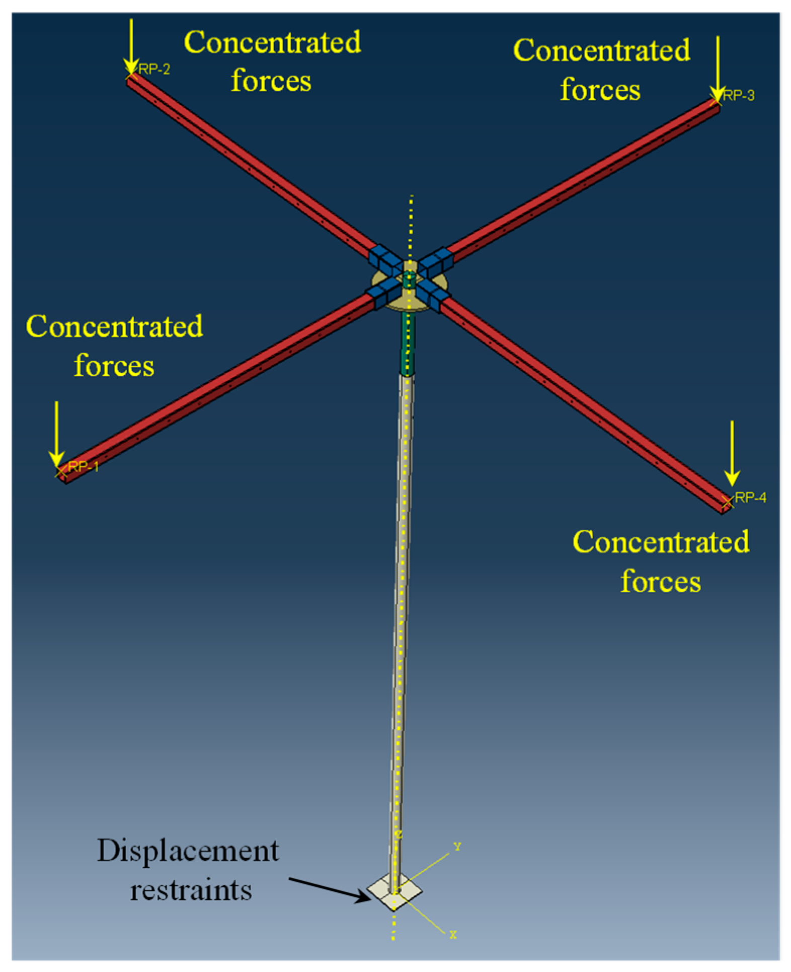
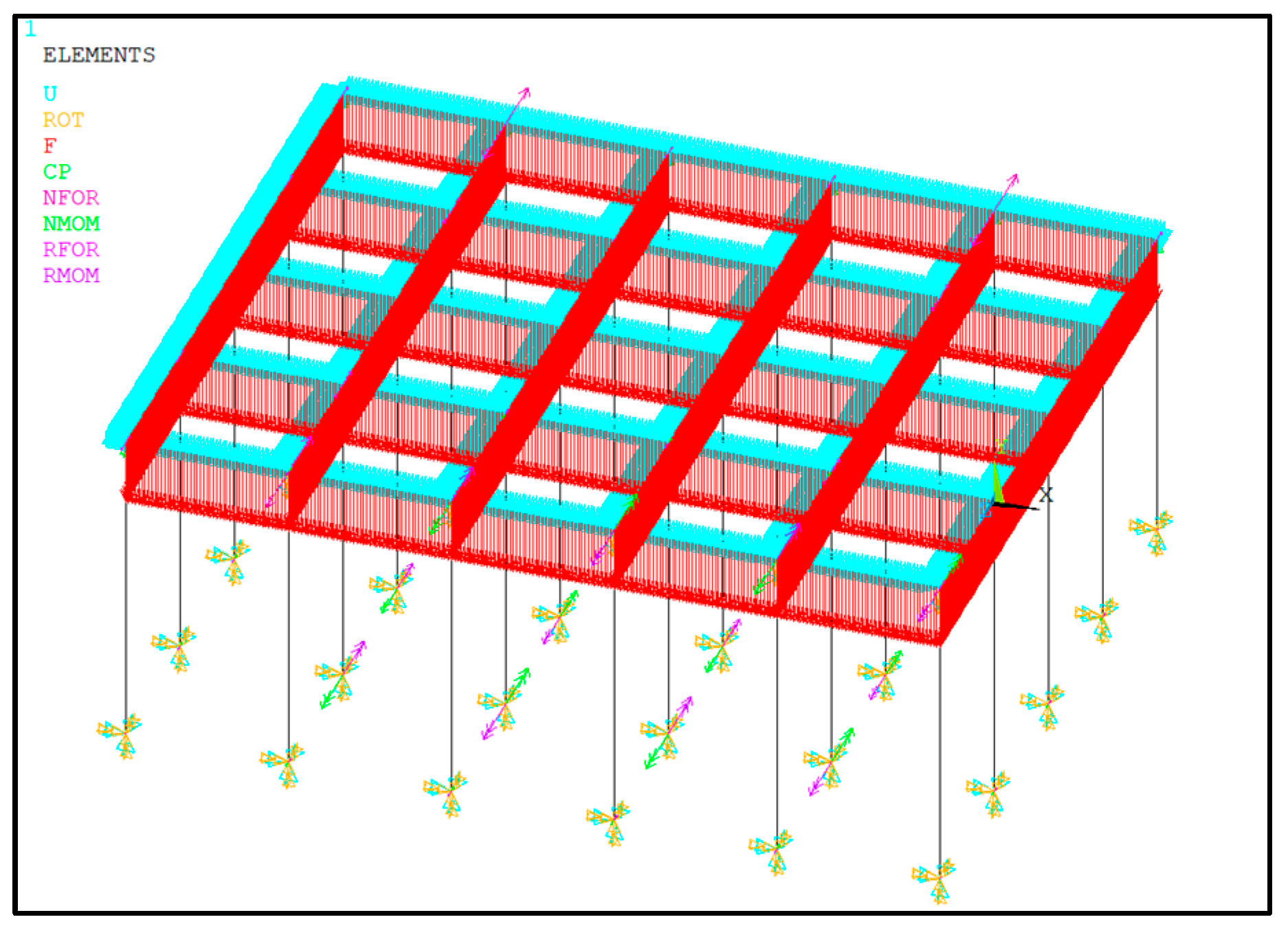
4.1. Numerical Simulation Method of the Buckling Behaviours

In this section, a numerical simulation method was proposed to analyse the buckling of the single-layer, single-span steel frame with the fixed column bases. Two steel frame forms, i.e., non-sway and sway steel frames, were considered, as shown in Figure 8. For both non-sway and sway steel frames, three beam–column node types were considered, i.e., rigid node, semi-rigid node and hinged node.
In numerical simulation, the beam element BEAM 189 was adopted to model the beams and columns. The beams and columns were meshed uniformly, and the maximum element size was 10 mm. In addition, the spring elements were set at the intersection points of the beams and columns to characterize the rigidities of the beam–column nodes. For the rigid node, semi-rigid node and hinged node, the rotation stiffnesses of the spring element were set as 106 kN·m/rad, 37.18 kN·m/rad and 0 kN·m/rad, respectively. To achieve the fixed column bases, the displacements and rotations of the bottom of the column were totally restrained. For the non-sway steel frame, the horizontal displacements of the beam–column nodes were restrained. For the sway steel frame, the horizontal displacements of the beam–column nodes were not restrained. As shown in Figure 8, concentrated loads were applied on the tops of the columns, and the linear buckling analyses of the non-sway and sway steel frames under different beam–column node types were performed. The buckling load Plin values were calculated, as shown in Table 1. According to Euler’s formula, the effective length factor μ values of the columns were derived using Equation (7).
μ = π 2 E I c P lin 1 L c
where Ic and Lc are the section inertia moment and length of the column, respectively. The effective length factor derived by the buckling load Plin values obtained in the numerical simulation was denoted as unum and the calculated values are listed in Table 1.
According to the book Fundamentals of Steel Structures [31], the effective length factors of the non-sway columns with the rigid node and hinged node were 0.580 and 0.700, respectively, and the effective length factors of the sway columns with the rigid node and hinged node were 1.078 and 2.000, respectively. As for the semi-rigid node, the effective length factor of non-sway and sway columns can be calculated from Equations (8) and (9), respectively.
μ = K 1 + 2 . 188 2 K 1 + 3.125
μ = K 1 + 0 . 532 K 1 + 0.133
where K1 is the linear stiffness of the column and calculated in Equation (10) as:
K 1 = I c L c
As for the non-sway and sway steel frames shown in Figure 8, the effective length factors determined by the theoretical formula, denoted as uth, are listed in Table 1. The relative errors (REs) between unum and uth were calculated and are listed in Table 1. It can be seen that the RE values between unum and uth are within 5%, indicating that the numerical simulation method for buckling behaviours proposed in this study was reasonable. The scaffold independent supporting system can be regarded as a more complex system incorporating several single-layer, single-span steel frames. Thus, it is credible that the verified finite element simulation can be utilised to analyse the buckling behaviour of the scaffold independent supporting system.
Thereafter, this numerical simulation method was adopted to analyse the buckling behaviour of the scaffold independent supporting system with the fixed column bases. Two frame forms, i.e., non-sway and sway frames, were considered. The element type and mesh density were the same as those of the single-layer, single-span steel frame. All the beam–column nodes were solved as semi-rigid nodes, and the rotation stiffness was set as 37.18 kN∙m/rad. For the real structures of the scaffold independent supporting system, the self-gravity of the upper structure was directly supported by the horizontal beams, and it was then transferred to the upright columns through the beam–column nodes. Thus, in the numerical simulation of the buckling behaviour of the scaffold independent supporting system, the concentrated forces were applied on the top of the upright column. The linear buckling analyses without considering initial imperfections were performed to determine the buckling load Plin and the effective length factor u. The buckling load Plin values of the non-sway and sway systems were calculated as 76.505 kN and 23.142 kN, respectively. The effective length factor u values of the non-sway and sway systems were calculated as 0.624 and 1.253, respectively. The deformations under the critical buckling failure states of the scaffold independent supporting systems are shown in Figure 9a,b for non-sway and sway systems, respectively.

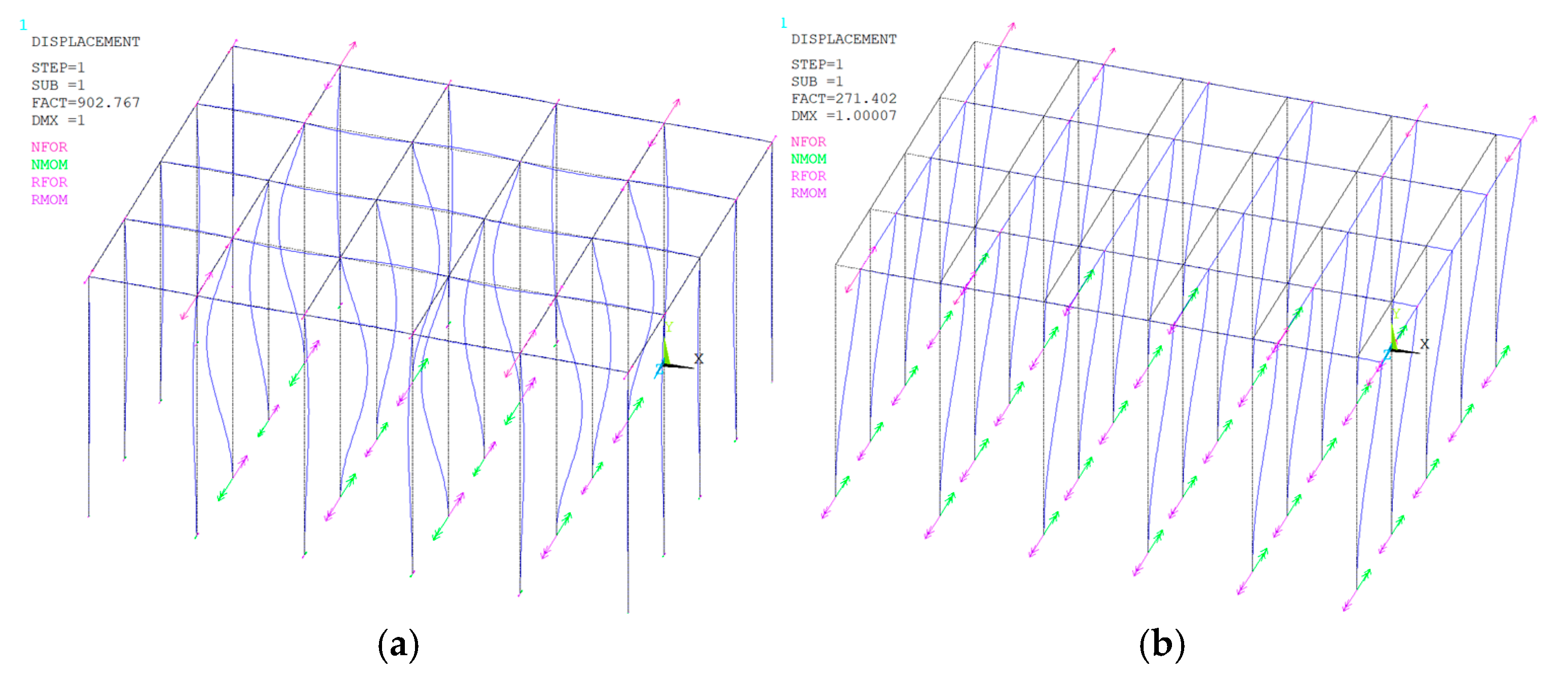
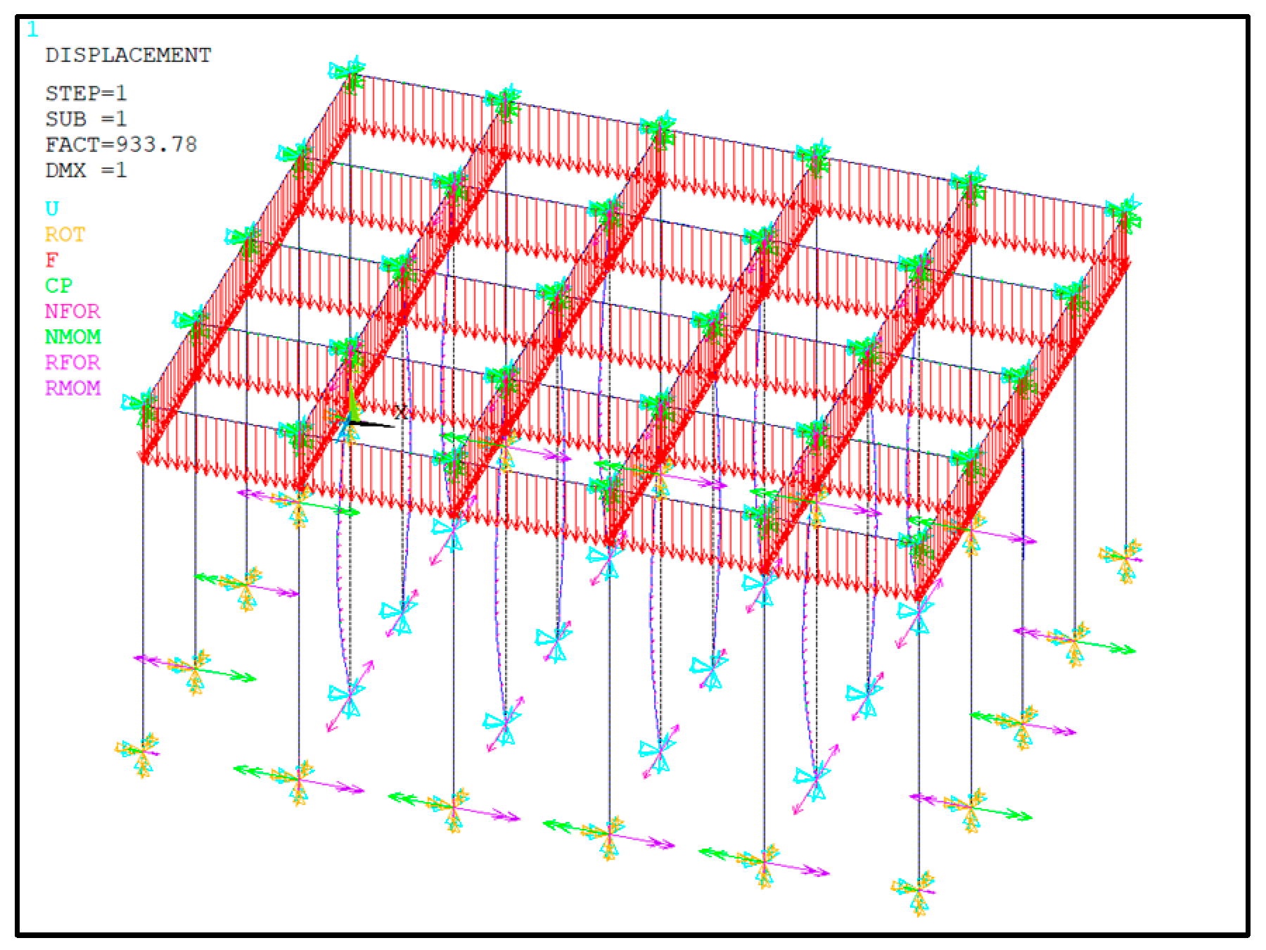
4.2. Buckling Behaviour of the Scaffold Independent Supporting System Under the Rigid Connections at All the Bottom Nodes

Numerical simulations were conducted to analyse the linear and nonlinear buckling behaviours of the scaffold independent supporting systems under the rigid connections at all the bottom nodes. In the numerical simulation, all the bottom nodes of the columns were regarded as rigid nodes, and the displacement and rotation restraints were applied at the bottom nodes of the columns. In addition, all the beam–column nodes were regarded as semi-rigid nodes, and the spring elements with a rotation stiffness of 37.18 kN∙m/rad were applied at the beam–column nodes. It is worthwhile to point out that the scaffold independent supporting system was a non-sway system, and the horizontal displacement restraints were applied at all the beam–column nodes. The finite element model of the scaffold independent supporting system with the corresponding restraints and spring elements is shown in Figure 10. In this section, different values of the column space lcol and the layer height hcol were adopted in the numerical simulations to investigate the effects of the column space lcol and the layer height hcol on the buckling behaviour of the scaffold independent supporting system.
Firstly, linear buckling analysis without considering initial imperfections was performed, and the calculated values of the buckling load Plin and the effective length factor μ under the linear buckling analysis were determined for different values of the column space lcol and the column height hcol, as listed in Table 2. The deformations of the scaffold independent supporting system are shown in Figure 11a,b for the first-order and second-order deformations, respectively. The linear buckling analysis was simple and highly efficient, and it was widely applied in practical engineering. Nevertheless, due to the existing initial imperfections, the actual buckling load of the scaffold independent supporting system would be less than that under a linear buckling assumption. To determine the actual buckling load, nonlinear buckling analysis considering geometric irregularities was performed. It should be noted that the finite element simulation of the linear buckling analysis has been verified to be reasonable in Section 4.1. Based on the linear buckling analysis, the nonlinear buckling analysis only considering the geometric irregularities was conducted by endowing an initial end displacement with the magnitude of 1/100 of the column length on the column. It is credible that the verified linear buckling analysis method is feasible to determine the nonlinear buckling behaviour only considering the geometric irregularities. The buckling load Pnon values under the nonlinear buckling analyses were determined for different values of the column space lcol and the column height hcol, as listed in Table 2. The decrement ratios of the buckling loads due to the initial imperfections, denoted as Rde, were calculated and are listed in Table 2. It can be seen from the table that the decrement ratios of the buckling loads due to the initial imperfections were within 3%, indicating that the initial imperfections had no significant effects on the buckling load of the scaffold independent supporting system. It is worth pointing out that only the initial end displacement with the magnitude of 1/100 of the column length was considered in the nonlinear buckling analysis. The decrement ratios of the buckling loads induced by other factors, e.g., the initial crack, local node failure, and installation error, should be explored further.
The variations of the effective length factors μ values with the column space lcol and the column height hcol are shown in Figure 12a and Figure 12b, respectively. It can be seen from Figure 12 that the column space lcol and the column height hcol had effects on the effective length factors. The effective length factors μ increased with the increase in the column spaces lcol, whereas it decreased with the increase in the column height hcol. In addition, the increasing and decreasing tendencies exhibited nearly linear tendencies. As shown in Figure 12a, when the column space lcol increased from 600 mm to 1800 mm, the increasing ratio of the effective length factor μ was 2.11%. As shown in Figure 12b, when the column space hcol increased from 2500 mm to 5000 mm, the decreasing ratio of the effective length factor μ was 5.53%. This indicates that the effects of the column space lcol and the column height hcol on the effective length factors were not significant.

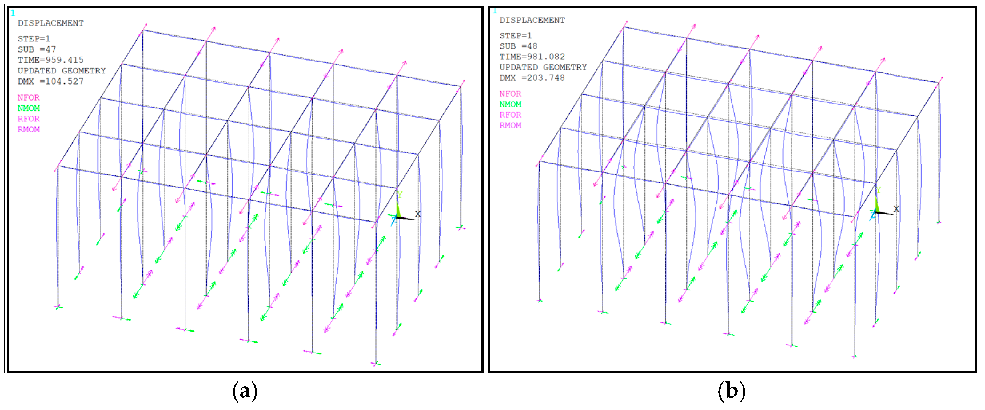
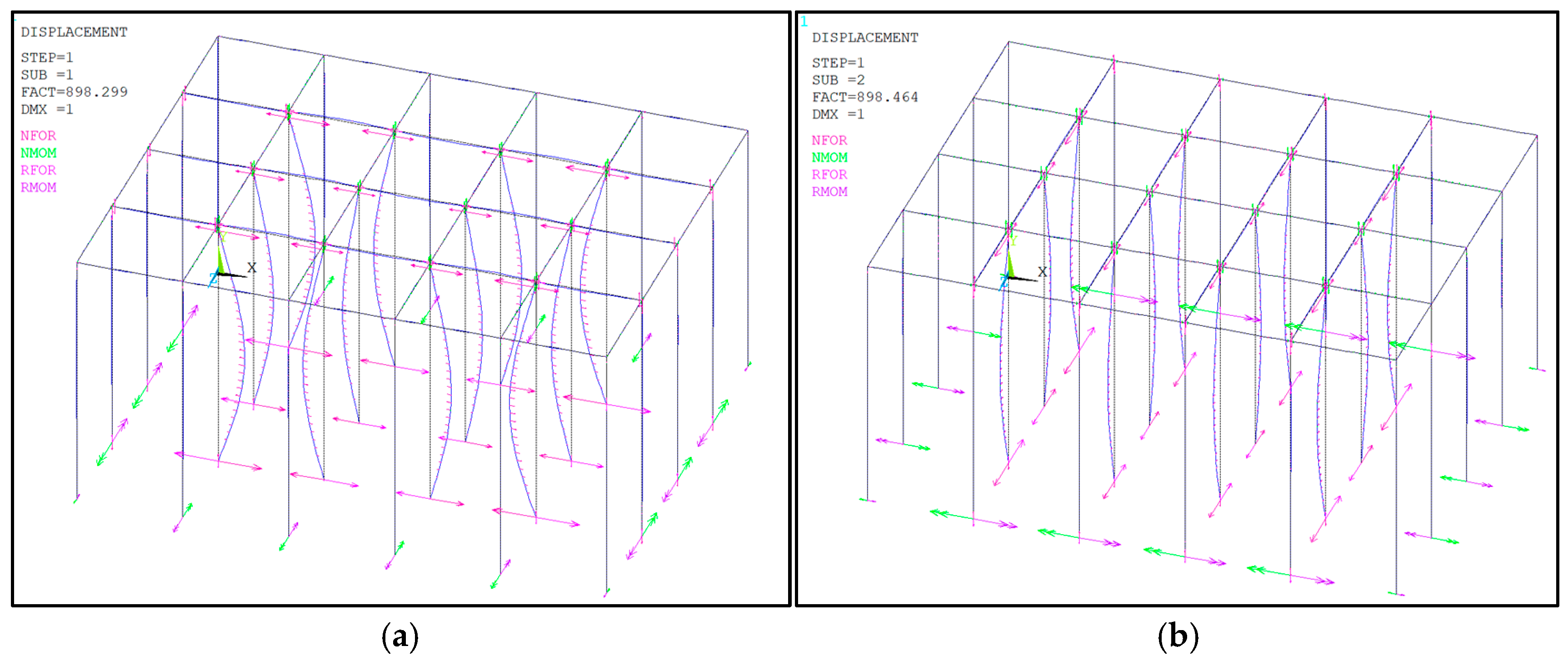
4.3. Buckling Behaviour of the Scaffold Independent Supporting System Under the Rigid Connections at the Bottom Side Nodes and the Hinged Connections at the Bottom Internal Nodes

Numerical simulation was conducted to analyse the buckling behaviour of the scaffold independent supporting system under the rigid connections at the bottom side nodes and the hinged connections at the bottom internal nodes. Comparing it with the boundary conditions mentioned in Section 4.2, the boundary condition in this section was closer to the actual situation. In the numerical simulation, the bottom side nodes of the columns were regarded as rigid nodes, and the displacement and rotation restraints were applied at the bottom side nodes of the columns. The bottom internal nodes of the columns were regarded as hinged nodes, and only the displacement restraints were applied at the bottom internal nodes of the columns. In addition, all the beam–column nodes were regarded as semi-rigid nodes, and the spring elements with a rotation stiffness of 37.18 kN∙m/rad were applied at the beam–column nodes. It is worthwhile pointing out that the scaffold independent supporting system was a non-sway system, and the displacement restraints were applied at all the beam–column nodes. The finite element model of the scaffold independent supporting system with the corresponding restraints and spring elements is shown in Figure 13. In this section, different values of the column space lcol and the layer heights hcol were adopted in the numerical simulations to investigate the effects of the column space lcol and the layer height hcol on the buckling behaviour of the scaffold independent supporting system.
Firstly, linear buckling analysis without considering initial imperfections was performed, and the values of the buckling load Plin and the effective length factor μ under the linear buckling analysis were determined for different values of the column space lcol and the column height hcol, as listed in Table 3. The deformations of the scaffold independent supporting system are shown in Figure 14a,b for the first-order and second-order deformations, respectively. Then, nonlinear buckling analysis considering geometric irregularities was performed, in which an initial end displacement with the magnitude of 1/100 of the column length was presupposed on the column. The buckling load Pnon values under the nonlinear buckling analyses were determined for different values of the column space lcol and the column height hcol, as listed in Table 3. The decrement ratios of the buckling load, Rde, were calculated and are listed in Table 3. It can be seen from the table that the decrement ratios of the buckling loads due to the initial imperfections were within 2%, indicating that the initial imperfections had no significant effects on the buckling load of the scaffold independent supporting system.
The variations in the effective length factors μ with the column space lcol and the column height hcol are shown in Figure 15a and Figure 15b, respectively. It can be seen from Figure 15 that the column space lcol and the column height hcol had effects on the effective length factors. The effective length factors μ increased with the increase in the column space lcol, but decreased with the increase in the column height hcol. In addition, the increasing and decreasing tendencies exhibited nearly linear tendencies. As shown in Figure 15a, when the column space lcol increased from 600 mm to 1800 mm, the increasing ratio of the effective length factor μ was 4.22%. As shown in Figure 15b, when the column space hcol increased from 2500 mm to 5000 mm, the decreasing ratio of the effective length factor μ was 5.87%. This indicates that the effects of the column space lcol and the column height hcol on the effective length factors were not significant.

5. Conclusions

This study investigated the buckling behaviour of the scaffold independent supporting system considering semi-rigid nodes. Firstly, a scaffold independent supporting system without the horizontal and diagonal braces was proposed. Then, numerical simulation was performed to calculate the rotation stiffness of the beam–column node. Finally, numerical simulations were performed to analyse the buckling behaviour and determine the effective length factors of the scaffold independent supporting systems under different conditions. Based on the numerical results, the following conclusions can be drawn.
(1)
A scaffold independent supporting system without horizontal and diagonal braces was proposed in this study. The scaffold independent supporting system consisted of horizontal beams located in the concrete formwork and upright columns, and at the beam–column nodes. The tops of the upright columns were connected by the horizontal beams to form a highly interconnected structure. There existed a lot of free space within the scaffold independent supporting system, which made it possible to conduct other operational work during the curing of concrete.
(2)
Finite element simulation was performed to calculate the mechanical responses at the beam-–column nodes in the scaffold independent supporting system. By establishing the refined finite element model, the mechanical response of the beam–column nodes was calculated, and the rotation stiffness of the beam–column nodes was determined as 37.18 kN·m/rad. According to the existing sorting method, the beam–column nodes in the scaffold independent supporting system were determined as semi-rigid nodes.
(3)
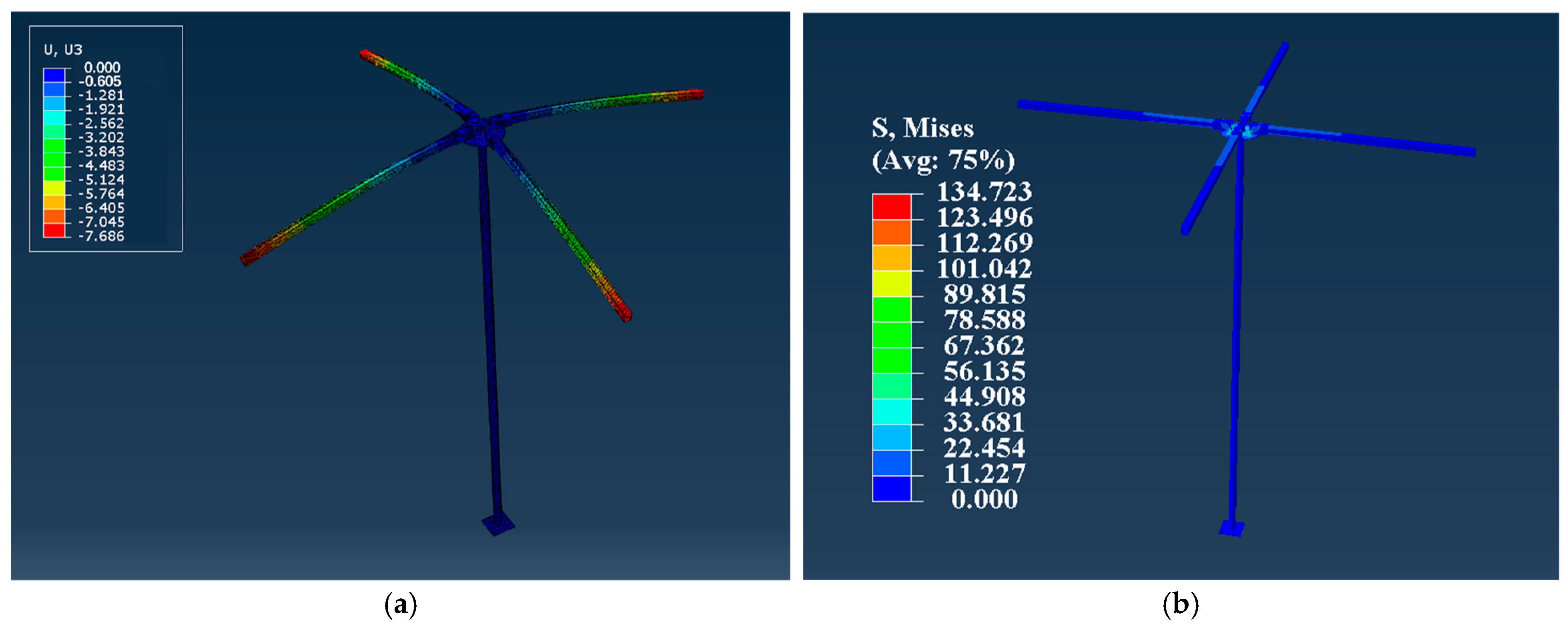
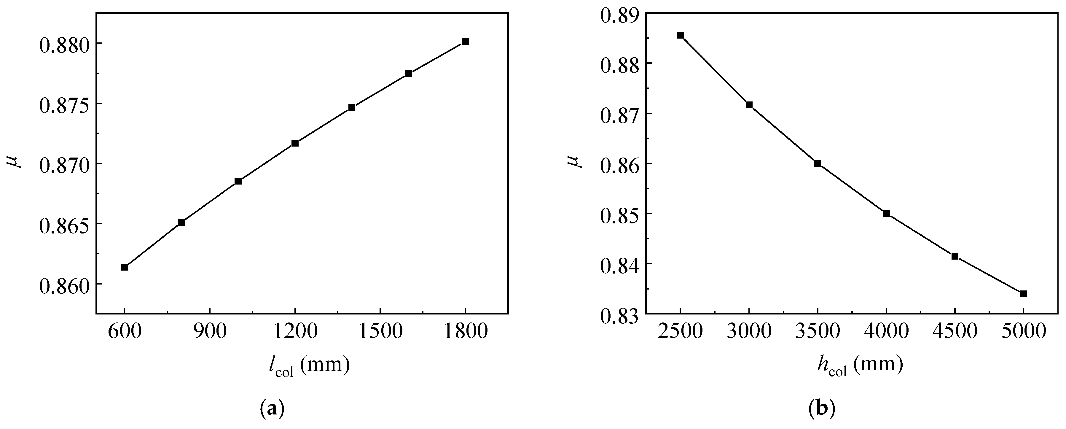
A numerical simulation method was proposed and verified in this study to analyse the buckling behaviour of the scaffold independent supporting system, in which the semi-rigid connection was characterized by setting the spring elements at the beam–column nodes. The linear and nonlinear buckling analyses were performed to calculate the buckling behaviour of scaffold independent supporting system. It was found that the effective length factor increased with the increase in the column space, but decreased with the increase in the column height. In addition, the buckling loads under the linear and nonlinear buckling analyses had no significant differences, indicating the initial imperfections had no significant effects on the buckling behaviour.
(4)
It is worthwhile to point out that only the initial end displacement with the magnitude of 1/100 of the column length was considered in the nonlinear buckling analysis. The decrement ratios of the buckling loads induced by other factors, e.g., the initial crack, local node failure and installation error, should be explored further. In addition, only the numerical simulation was conducted to analyse the buckling behaviour of the scaffold independent supporting system, and the rationality of the numerical simulation was verified by the analytical expressions. The experimental investigation into the mechanical response at the semi-rigid nodes under fatigue loading will be conducted later, and extensive exploration of the buckling behaviour of the scaffold independent supporting system will be reported later.

Author Contributions

Conceptualization, W.D. and B.Z.; Methodology, R.L. and Z.L.; Formal analysis: Y.W.; Investigation, R.L., Q.T. (Qian Tao) and Y.W.; Writing—original draft, R.L., Q.T. (Qihou Tan) and Z.L.; Writing—review and editing, B.Z. and Q.T. (Qian Tao); Supervision, W.D. and B.Z.; Project administration, W.D., B.Z. and Q.T. (Qihou Tan); Funding acquisition, Q.T. (Qian Tao) and Z.L. All authors have read and agreed to the published version of the manuscript.

Funding

This research was funded by China MCC5 Group Corp., Ltd. (Grant No. WY2023B007).

Data Availability Statement

The data presented in this study are available on request from the corresponding author. The data are not publicly available due to privacy.

Acknowledgments

The funder—China MCC5 Group Corp., Ltd.—and their support is gratefully acknowledged. The authors also wish to thank the anonymous reviewers for their thorough review of the article and their constructive advice.

Conflicts of Interest

Authors Qian Tao, Zhihua Liu and Qihou Tan were employed by China MCC5 Group Corp., Ltd. The remaining authors declare that the research was conducted in the absence of any commercial or financial relationships that could be construed as a potential conflict of interest.

References

  1. Pieńko, M.; Błazik-Borowa, E. Numerical analysis of load-bearing capacity of modular scaffolding nodes. Eng. Struct. 2013, 48, 1–9. [Google Scholar] [CrossRef]
  2. Dong, J.; Liu, H. Effective length correction factor of disc-buckle type scaffolding by considering joint bending stiffness and geometrical size. PLoS ONE 2022, 17, 0276340. [Google Scholar] [CrossRef] [PubMed]
  3. Liu, H.; Jia, L.; Wen, S. Experimental and theoretical studies on the stability of steel tube-coupler scaffolds with different connection joints. Eng. Struct. 2016, 106, 80–95. [Google Scholar] [CrossRef]
  4. Zhang, H.; Chandrangsu, T.; Rasmussen, K. Probabilistic study of the strength of steel scaffold systems. Struct. Saf. 2010, 32, 393–401. [Google Scholar] [CrossRef]
  5. Peng, J.; Yen, T.; Kuo, C.; Chan, S. Analytical and experimental bearing capacities of system scaffolds. J. Zhejiang Univ.-Sci. A Appl. Phys. Eng. 2009, 10, 82–92. [Google Scholar] [CrossRef]
  6. Liu, H.; Meng, Y.; Jia, L. Structural behavior of steel tube and coupler scaffolds with stability strengthening details. Int. J. Steel Struct. 2018, 18, 79–95. [Google Scholar] [CrossRef]
  7. Peng, J.; Wu, C. Experimental and numerical studies of practical system scaffolds. J. Constr. Steel Res. 2013, 91, 64–75. [Google Scholar] [CrossRef]
  8. Zhang, H.; Rasmussen, K.; Ellingwood, B.R. Reliability assessment of steel scaffold shoring structures for concrete formwork. Eng. Struct. 2012, 36, 81–89. [Google Scholar] [CrossRef]
  9. Xie, X.; Chen, G.; Yin, L. Multi-parameter simulation method of semi-rigid node of steel tubular scaffold with couplers. J. Civ. Environ. Eng. 2019, 41, 92–103. [Google Scholar]
  10. Prabhakaran, U.; Beale, R. Analysis of scaffolds with connections containing looseness. Comput. Struct. 2011, 89, 1944–1955. [Google Scholar] [CrossRef]
  11. Zheng, Y.; Guo, Z. Investigation of joint behavior of disk-lock and cuplok steel tubular scaffold. J. Constr. Steel Res. 2021, 177, 106415. [Google Scholar] [CrossRef]
  12. Liu, C.; He, L.; Wu, Z. Experimental and numerical study on lateral stability of temporary structures. Arch. Civ. Mech. Eng. 2018, 18, 1478–1490. [Google Scholar] [CrossRef]
  13. Chandrangsu, T.; Rasmussen, K. Investigation of geometric imperfections and joint stiffness of support scaffold systems. J. Constr. Steel Res. 2011, 67, 576–584. [Google Scholar] [CrossRef]
  14. Ihaddoudène, A.; Saidani, M.; Chemrouk, M. Mechanical model for the analysis of steel frames with semi rigid joints. J. Constr. Steel Res. 2009, 65, 631–640. [Google Scholar] [CrossRef]
  15. Zhao, Z.; Liu, H.; Liang, B. Novel numerical method for the analysis of semi-rigid jointed lattice shell structures considering plasticity. Adv. Eng. Softw. 2017, 114, 208–214. [Google Scholar] [CrossRef]
  16. Bjorhovde, R.; Colson, A. Classification system for beam-to-column connections. J. Struct. Eng. 1990, 116, 3059–3076. [Google Scholar] [CrossRef]
  17. Jones, S.; Kirby, P.; Nethercort, D. The analysis of frames with semi-rigid connections—A state-of-the-art report. J. Constr. Steel Res. 1983, 3, 2–13. [Google Scholar] [CrossRef]
  18. Chan, S.; Huang, H.; Fang, L. Advanced analysis of imperfect portal frames with semirigid base connections. J. Eng. Mech. 2005, 131, 633–640. [Google Scholar] [CrossRef]
  19. Özel, H. Modeling of the Nonlinear Behavior of Semi-Rigid Connections in Steel Framed Structures and Its Influence on Three Dimensional Analysis of Structural Systems. Ph.D. Thesis, Middle East Technical University, Ankara, Türkiye, 2019. [Google Scholar]
  20. Dong, J.; Liu, H. Buckling behavior of a wheel coupler high-formwork support system based on semi-rigid connection joints. Adv. Steel Constr. 2022, 18, 425–435. [Google Scholar]
  21. Zhang, L.; Liu, J.; Tang, Q.; Liu, Z. A numerical study on rotational stiffness characteristics of the disk lock joint. J. Constr. Steel Res. 2023, 207, 107968. [Google Scholar] [CrossRef]
  22. Chenaghlou, M.; Nooshin, H.; Harding, J. Proposed mathematical model for semi-rigid joint behaviour (M-θ) in space structures. Int. J. Space Struct. 2014, 29, 71–80. [Google Scholar] [CrossRef]
  23. Li, P.; Chen, G.; Qiu, J.; Qian, J.; Ding, D.; Jian, B.; Zhang, X.; Xiong, G. Experimental and numerical investigation into the load-carrying capacity of aluminium alloy H-sectional stocky columns under axial compression. J. Build. Eng. 2024, 87, 108777. [Google Scholar] [CrossRef]
  24. Chen, G.; Li, P.; Bao, H.; Huang, Y.; Liu, C.; Zhang, T.; Xiong, G. Design method for axially compressed H-sectional aluminium alloy slender column based on CSM. Thin-Walled Struct. 2024, 205, 112417. [Google Scholar] [CrossRef]
  25. Li, P.; Chu, S.; Qin, S.; Ding, H.; Luo, N.; Yu, Y.; Zhang, T.; Xiong, G. Optimisation of prestressed stayed steel columns based on strengthen elitist genetic algorithm. J. Constr. Steel Res. 2025, 227, 109324. [Google Scholar] [CrossRef]
  26. Ji, M. Study on the Node Performance of Disc-Type Steel Pipe Support and the Stable Bearing Capacity of the Support. Master’s Thesis, Xi’an University of Technology, Xi’an, China, 2024. [Google Scholar]
  27. Wang, N. Study on the Mechanical Properties of Semi-Rigid Nodes of Disc-Type Steel Pipe Scaffolding. Master’s Thesis, Xi’an University of Technology, Xi’an, China, 2023. [Google Scholar]
  28. Xiao, H. Study on Node Stiffness and Support Stability of Disc-Type Steel Pipe Support. Master’s Thesis, Kunming University of Science and Technology, Kunming, China, 2022. [Google Scholar]
  29. Liu, H. Study on Mechanical Properties and Stability of a New Disc-Type Lattice Support. Master’s Thesis, Chongqing Jiaotong University, Chongqing, China, 2023. [Google Scholar]
  30. JGJ/T 300-2013; Technical Code for Temporary Support Structures in Construction. China Architecture and Building Press: Beijing, China, 2013.
  31. Chen, S.; Hao, J. Fundamentals of Steel Structures, 5th ed.; China Architecture and Building Press: Beijing, China, 2023. [Google Scholar]
Figure 1. Schematic diagrams of the scaffold independent supporting system and beam–column node. (a) Scaffold independent supporting system; (b) Beam–column node.
Buildings 15 00443 g001
Figure 2. Three-dimensional model of the beam–column node after simplification. (a) Upper view; (b) Lower view.
Buildings 15 00443 g002
Figure 3. Three-dimensional finite element model of beam–column node after reasonable mesh. (a) Upper view; (b) Lower view.
Buildings 15 00443 g003
Figure 4. Displacement restraints and contact elements applied in the three-dimensional model of the beam–column node.
Buildings 15 00443 g004
Figure 5. Mechanical responses of the beam–column node under the four concentrated forces. (a) Vertical displacement contour; (b) von Mises stress contour.
Buildings 15 00443 g005
Figure 6. Assessment of rigidness of node based on the M* − θ* curve.
Buildings 15 00443 g006
Figure 7. Comparison of the rigidnesses of beam–column nodes adopted in this study and quoted from other references (“A” means the semi-rigid node in this study).
Buildings 15 00443 g007
Figure 8. Calculation models of the single-layer, single-span steel frames. (a) Non-sway steel frame; (b) Sway steel frame.
Buildings 15 00443 g008
Figure 9. Deformations under the critical buckling failure states of the scaffold independent supporting systems with the fixed column bases. (a) Non-sway steel frame; (b) Sway steel frame.
Buildings 15 00443 g009
Figure 10. Finite element model of the non-sway scaffold independent supporting system under the rigid connections at all the bottom nodes.
Buildings 15 00443 g010
Figure 11. Deformations of the scaffold independent supporting system under the rigid connections at all the bottom nodes for lcol = 1200 mm and hcol = 3000 mm. (a) First-order deformation; (b) Second-order deformation.
Buildings 15 00443 g011
Figure 12. Variations in the effective length factor μ values with the column space lcol and the column height hcol for the scaffold independent supporting system under the rigid connections at all the bottom nodes. (a) Variation in μ with lcol; (b) Variation in μ with hcol.
Buildings 15 00443 g012
Figure 13. Finite element model of the non-sway scaffold independent supporting system under the rigid connections at the bottom side nodes and the hinged connections at the bottom internal nodes.
Buildings 15 00443 g013
Figure 14. Deformations of the scaffold independent supporting system under the rigid connections at the bottom side nodes and the hinged connection at the bottom internal nodes for lcol = 1200 mm and hcol = 3000 mm. (a) First-order deformation; (b) Second-order deformation.
Buildings 15 00443 g014
Figure 15. Variations in the effective length factors μ with the column space lcol and the column height hcol for the scaffold independent supporting system under the rigid connections at the bottom side nodes and the hinged connection at the bottom internal nodes. (a) Variation in μ with lcol; (b) Variation in μ with hcol.
Buildings 15 00443 g015
Table 1. Effective length factor u values of the columns for the single-layer, single-span steel frames.
Steel Frame FormsNode TypesPlin (kN)unumuthR.E. (%)
Non-swayRigid73.4760.576 0.5800.69
Semi-rigid62.5200.624 0.6443.11
Hinged48.5940.708 0.7001.14
SwayRigid21.6321.061 1.0781.58
Semi-rigid15.5171.253 1.2401.05
Hinged5.9382.025 2.0001.25
Table 2. Buckling loads and effective length factors of the scaffold independent supporting system under the rigid connections at all the bottom nodes.
hcol (mm)lcol (mm)Plin (kN)μPnon (kN)Rde (%)
2500120089.1680.63387.1782.23
3000120063.7890.62462.3632.24
3500120048.0750.61647.0022.23
4000120037.6350.60936.7962.23
4500120030.3240.60329.6472.23
5000120024.9930.59824.4352.23
300060065.2710.61763.8162.23
300080064.7270.61963.2802.23
3000100064.2380.62262.8042.23
3000120063.7890.62462.3632.24
3000140063.3700.62661.9542.23
3000160062.9740.62861.5692.23
3000180062.5970.63061.2012.23
Table 3. Buckling loads and effective length factors of the scaffold independent supporting system under the rigid connections at the bottom side nodes and the hinged connections at the bottom internal nodes.
hcol (mm)lcol (mm)Plin (kN)μPnon (kN)Rde (%)
2500120045.5960.88644.8461.65
3000120032.6820.87232.1451.64
3500120024.6680.86024.2631.64
4000120019.3320.85019.0141.64
4500120015.5870.84215.3311.64
5000120012.8530.83412.6421.64
300060033.4700.86132.9311.61
300080033.1810.86532.6471.61
3000100032.9210.86932.3801.64
3000120032.6820.87232.1451.64
3000140032.4610.87531.9271.64
3000160032.2530.87831.7231.64
3000180032.0580.88031.5311.64
Disclaimer/Publisher’s Note: The statements, opinions and data contained in all publications are solely those of the individual author(s) and contributor(s) and not of MDPI and/or the editor(s). MDPI and/or the editor(s) disclaim responsibility for any injury to people or property resulting from any ideas, methods, instructions or products referred to in the content.

