1. Introduction
As one of the best techniques for dealing with a poor foundation, grouting technology has become an effective way to improve the performance of foundations, prevent ground subsidence, and repair potholes. Grouting technology has a wide application range, high strength, low noise, no pollution, and minimal working requirements, being especially suitable for seepage prevention and reinforcement projects of reservoir and dam infrastructure [
1,
2,
3]. When formation permeability is good (permeability coefficient greater than 10
−4 cm/s), using conventional cement or wet-milling cement grouting can achieve good results. A cement slurry is used to grout the weak zone and large cracks of a poor geological body to form a closed system and increase its structural strength, mainly including an ordinary cement slurry, ultrafine cement slurry, and wet grinding fine cement slurry [
4].
However, for low-permeability, soft fractured zones and mud layers (permeability coefficient k < 10
−4 cm/s), cement slurry can be relatively unsuitable for filling fine fractures and shale structures, so it struggles to meet engineering requirements [
5,
6,
7]. Chemical grouting technology can improve the integrity of building structures and effectively enhance their bearing capacity and impermeability by forming cement bodies between grouting materials and concrete [
8,
9,
10]. Compared with cement slurries, the particle size of chemical grouting materials is not fixed, and the gel time can be freely controlled according to the actual engineering needs, resulting in good perfusion ability, so the above dilemma can be well solved [
11,
12,
13]. Fang et al. [
14] revealed that the use of ultrafine cement instead of ordinary Portland cement as a grouting material can produce more waterproof and durable mortar, with better injectability and less settlement. Adding silicone to cement-based grout can improve its water resistance, greatly improve its freeze–thaw resistance, and improve its grouting ability. Zhang et al. [
15] studied the grouting reinforcement mechanism of broken coal by using traditional materials, namely, superfine cement (SC) and aluminate cement (AC), as well as self-developed polymer foaming (PF) grouting materials. The mechanical test results showed that the residual strength of the crushed coal after grouting was improved to different degrees, and the PF material had the most significant strengthening effect on the crushed coal. The SEM results showed that the slurry–coal interface structure of the SC and AC materials was relatively loose, while the interface structure of the PF material and coal was the closest, showing acceptable molecular compatibility. Zhang et al. [
16] successfully prepared a modified cement–sodium silicate grouting material for pre-reinforcing loose deposit tunnels. The proposed new grouting materials were applied for the reinforcement of loose accumulation tunnels. The results showed that C-S-P had good grouting and mechanical properties, which met the requirements for the rapid excavation of loose accumulation tunnels.
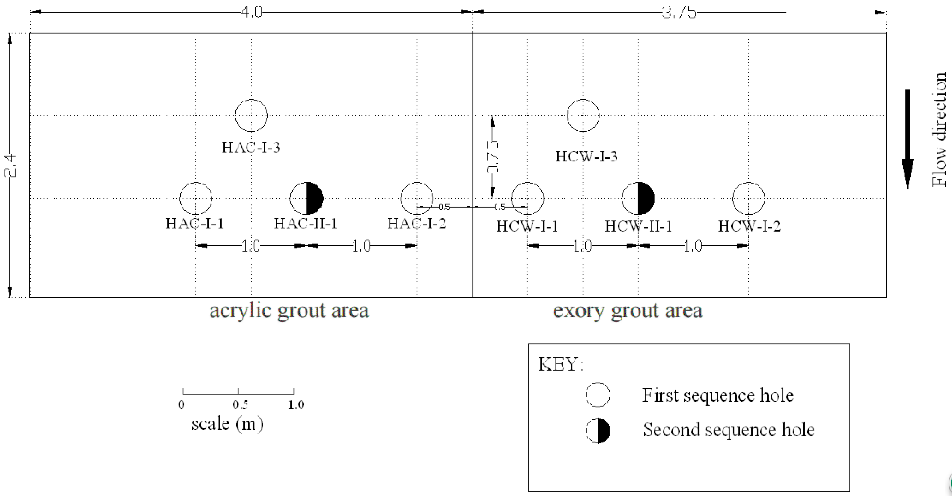
Although the usage of the cement–chemical compound grouting method to address foundation defects has yielded good results, there have been no improvements in the performance of in situ, compact, low-strength, and fine grains during the treatment of flexure fracture zones. Therefore, this paper reports on a full-scale field test that was conducted to assess the performance of wet-milling cement and chemical compound grouting used in the same hole to reinforce a flexural fracture zone in the Xiangjiaba Hydropower Station. The particle size of the wet-milling fine cement, the main properties of a CW permeable epoxy grouting material, and the gel properties of an AC-Ⅱ acrylate grouting material were tested in a laboratory. Meanwhile, the clastic structure sandstone in the test area was selected for epoxy grouting and acrylate grouting laboratory tests, and its mechanical properties were tested. In a field production test, eight injection wells of cement–chemical compound grouting materials were installed in the testing area and distributed in two experimental areas. Four injection wells of cement–epoxy resin and four injection wells of cement–acrylic acid salts, both in three rows with curtain spacing, were used. The field test results fully demonstrate that the selection of composite grouting materials with excellent performance and a suitable grouting process can be used to reinforce flexural fracture zones to restore the overall structure and provide a reference for similar safety hazards, engineering repairs, and reinforcements.
2. Site Characterization
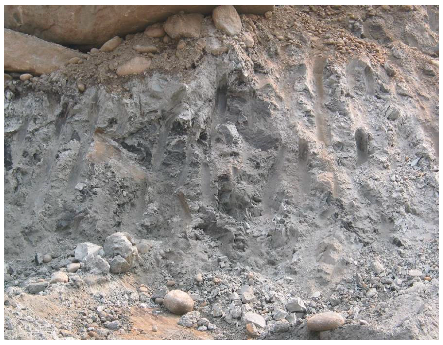
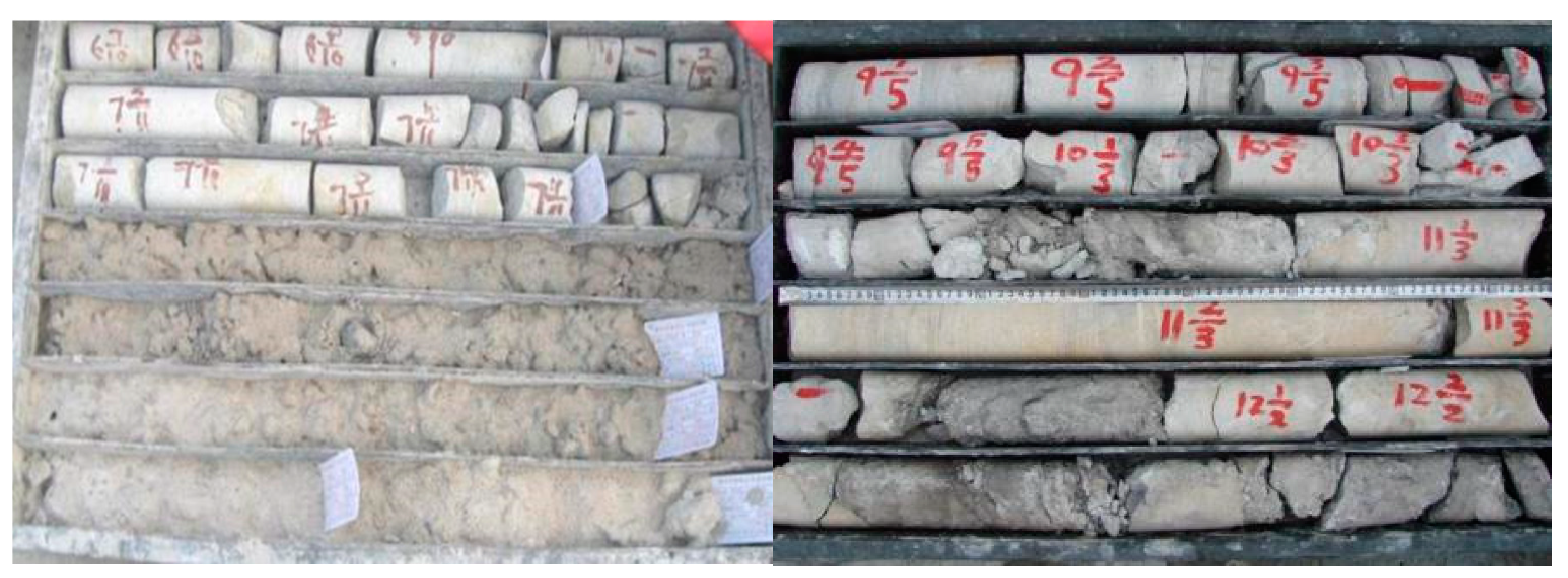
The compound grouting test area was located on a platform upstream of discharge dam 5 to the discharge dam 6, with the dams ranging from 0–87 m to 0–97 m and the right dam ranging from 0 + 78 m to 0 + 91 m, with an elevation of 257 m. The flexural fracture zone underlaid this area. The elevation of the top surface ranged from 214 m to 190 m, the thickness was 19.5–50.7 m, the average thickness was 35.1 m, and it was mainly composed of cataclastic-structured and elastic-structured sandstones. It contained 60.7 percent cataclastic-structured sandstones and 39.3 percent elastic-structured sandstones. The clastic substances in the flexural core of the crushed zone in the test area were shown in
Figure 1.
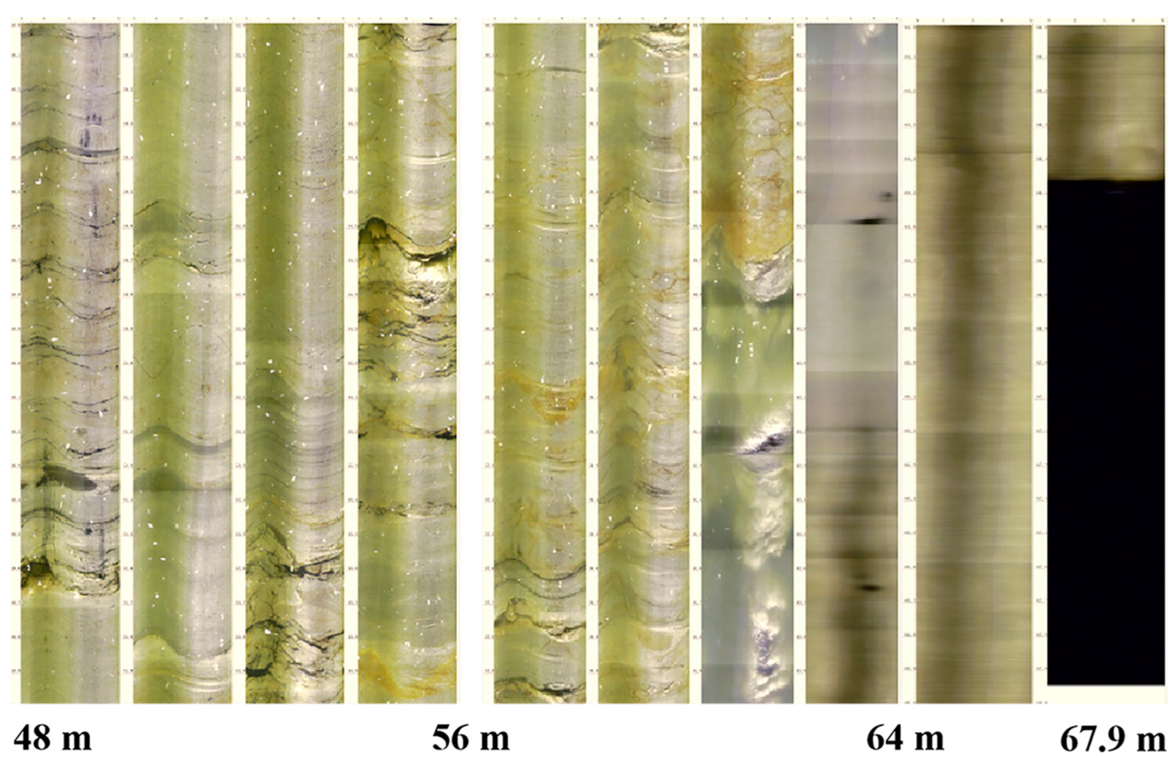
The flexural fracture zones were all deeply buried underground at a depth of approximately 65 m, and the processing depth was between 55 m and 74 m. The whole rock in the upper part of the test area was quite thick (36 m–60 m), and the total underlying flexural fracture zone was also thick (35.1 m) (
Figure 2). This area was ideal for a grouting test given the minimal interference from construction. The structure was mainly composed of fragments and debris in the flexural fracture zone, especially fine particles from the debris structure, with a low in situ water content (approximately 4%), high density (2.3 g/cm
3), as well as a low-intensity and small osmotic coefficient (10
−6 cm/s). This poorly irrigable structure easily collapsed under the influence of water.
6. Compound Grouting Procedure
Wet-milling superfine cement–chemical grout was injected into each well using the porthole closed-cycle grouting method. The chemical grouting materials, including epoxy grouting material and acrylate grouting material, were injected as a compound grouting into the same hole under pressure. First, the sequence I holes were complete, and then we moved on to the sequence II holes. The previous geological exploration results showed that the deflection of the fracture belt was buried approximately 65 m deep, and the grouting depth was less than 55 m, so we buried the pipe. The compound grouting was accomplished using a four-stage, top–bottom process. The blocking position was 0.5 m higher than that of top of the grouting section. Stages 1, 2, 3, and 4 were located at depths of approximately 55–60 m, 60–65 m, 65–70 m, and 70–74 m, respectively. A drilling bit with a diameter of 60 mm was used to drill the hole for the wet-milling superfine cement grouting. After the cement slurry was solidified for 12 h, the chemical slurry was poured with a 75 mm diameter drill, and the chemical grouting hole was sealed after the hole was full. This process was repeated after the injection of each of the eight wells, and each stage was isolated by treating the double packer during the grouting.
The designed pressure of the wet-milling fine cement grouting was 3.5 MPa, which was the pressure of the curtain grouting in the holes of middle row III. Water–cement ratios of 3:1, 2:1, 1:1, 0.8:1, and 0.5:1 were adopted according to the changes in the pressure and grouting rate. The water–cement ratio was 3:1 at the beginning of grouting. If the grouting pressure remained unchanged, the grouting rate continued to decrease, or the grouting rate remained unchanged while the pressure increased uniformly, the water–cement ratio did not change. If the slurry volume reached more than 300 L, the filling time reached 30 min, or the grouting pressure and grouting rate did not significantly vary, a grouting level with a strong water–cement ratio slurry was used instead. The relationship between grouting pressure and grouting rate was controlled according to
Table 2.
6.1. Epoxy Resin Grouting Process
According to the experience obtained with using epoxy resin grouting materials in the Three Gorges fault treatment process, grout should be selected according to the pressure and grouting rate. The proportions of epoxy resin grouting materials, referring to the changes in pressure and grouting rate, were as shown in the following standards:
(1) CW511 epoxy resin grouting material (6:1) should be used for filling pipe entrances and screen plasma.
(2) When the pressure of a grouting rises slowly or changes little after more than 4 h, an epoxy resin grouting material (5:1) can be used as a replacement. When readings on the pressure gauge and the actual injection rate are seriously mismatched (when the pressure is 1 MPa–1.5 MPa, and the flow rate is greater than 0.5 kg/min), the grouting material should be changed to CW512 (6:1).
(3) When CW512 (5:1) is used for more than 6 h, if the injection rate is still unchanged or increases and the pressure has not changed or has declined, CW511 epoxy resin grouting material (6:1) should be used instead of CW512 (5:1).
(4) When the unit injection quantity is over 75 kg/m but the ending standard has not been reached, or the readings on the pressure gauge and the injection rate are seriously mismatched, the grouting for coagulation should be stopped, and the pipe hole should be filled with a large quantity of CW511 (6:1) grouting material before curing.
6.2. Acrylate Material Grouting Process
The grouting pressure and injection rate of the HAC chemical grouting are shown in
Table 3.
6.3. The End Standard of Chemical Grouting
Usually, when the grouting pressure reaches the designed pressure, the grouting rate is ≤0.02 kg/min, and grouting is continued for 30 min or until the gelling time, at which point the grouting can be ended. Before the final grouting, we piped the plasma above the hole section into the bedrock fissure with water when the plasma absorption rate (within 5 min) was ≤0.5 L/min to reduce the blocking of the pipe by the grouting slurry. However, the amount of slurry in the pipeline above the grouting section must be accurately calculated, and the water consumption should not exceed this value. It was strictly prohibited to place water in the grouting crack. The amount of water consumed was calculated using the actual grouting amount. After the final batch of grouting slurry was condensed for 1 h, we loosened the obstruction, pulled out the pipe, cleaned the hole, and moved on to the next section of drilling and grouting. At the end of whole chemical grouting process of the hole, we sealed the hole with 0.5:1 cement–water slurry with the grouting sealing method.
The average unit injection quantity of the CW510 epoxy resin grouting material was 143.28 kg/m in the experimental epoxy zone. The average unit injection quantity of the sequence I holes (HCW-I-1, HCW-I-2, HCW-I-3) was 171.04 kg/m and that of the sequence II hole (HCW-II-1) was 114.08 kg/m. The average unit quantity of the sequence II hole was 33% less than that of the sequence I holes, which was in line with the depression law of grouting and indicated that the CW510 epoxy resin grouting material penetrated into the flexural fracture zone and enhanced the overall strength of the fracture zone, achieving the purpose of seepage prevention. The average unit injection quantity of the HAC grouting material was 12.68 kg/m in the acrylate experimental zone. The average unit injection quantity of the sequence I holes (HAC-I-1, HAC-I-2, HAC-I-3 hole) was 116.8 kg/m and that of the II sequence hole (HAC-II-1) was 8.28 kg/m. The average unit injection quantity of the HAC grouting material was generally small in the acrylate experimental zone, indicating that the ability of the acrylate grouting material to penetrate into the flexural fracture zone was relatively poor.
7. Results and Discussion
7.1. Results of the Normal Water Pressure Tests
The water pressure of the inspection holes was 2 MPa (the full pressure was 2.265 MPa). The permeability rates of each segment are shown in
Table 4.
The average permeability rate before compound grouting was 3.05 Lu in the HCW zone. Permeable rates of more than 1 Lu accounted for 87.5% and 0.5 Lu~1 Lu accounted for 12.5% in the area. After grouting, the permeability rate of the inspected hole was less than 0.15 Lu, and the average permeability rate was 0.073 Lu, which was a significant decrease. The average permeability rate of the HAC area before compound grouting was 3.52 Lu. Permeable rates of more than 1 Lu accounted for 87.5% and less than 0.5 Lu accounted for 12.5% in the area. The permeability rate was less than 0.120 Lu after grouting, which was a substantial decline. The normal water pressure in the HCW area was significantly stronger than in the HAC area.
7.2. Results of Failure Water Pressure Tests
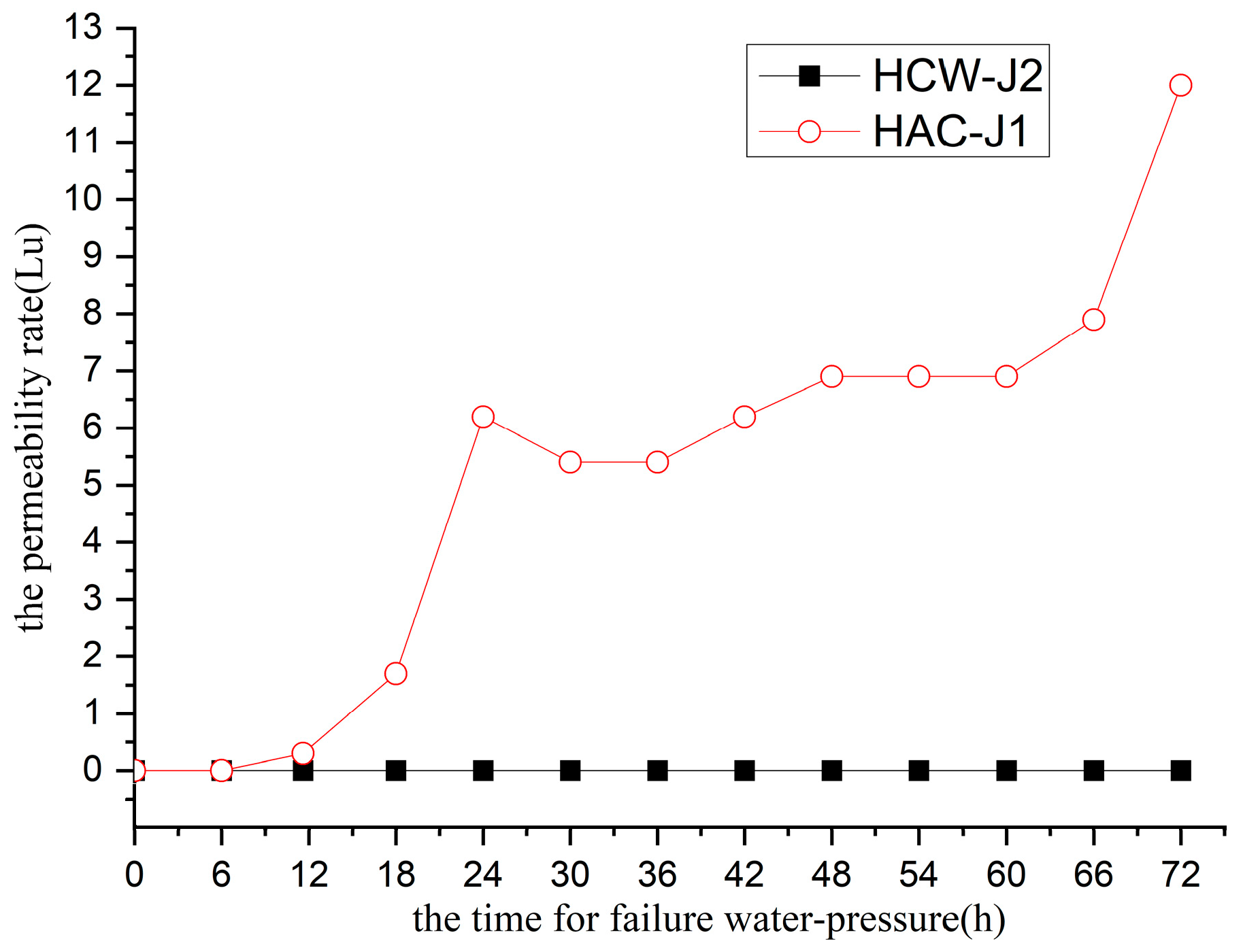
The failure water pressure test started at 1.5 MPa; the pressure was increased 0.1 MPa per hour and stayed at a pressure of 2.0 MPa for 72 h (
Figure 4). Under the full pressure of 2.265 MPa, the permeability rate of access hole HCW-J2 in the HCW area was 0 Lu. After 11.6 h of the water pressure test in hole HCW-J2 in the HCW area, the permeability rate was 0.3 Lu. The results of the failure water pressure in the holes in the HCW area showed that the water permeability was basically impervious and remained unchanged with the increase of pressure and time. The water permeability of the inspection holes in the HAC area continuously increased with time. It increased rapidly at 24 h, remained stable from 24 h to 60 h, and increased rapidly again after 60 h. The main reason was that the consolidation bodies formed by the HAC grouting material experienced water swelling; coupled with the inhomogeneity of the soil being poured, the consolidation bodies absorbed water and swelled at 24 h, forming a gel, blocking part of the pores, resulting in an uneven decrease in water permeability. After 42 h, with the increase in pressure, the local gel was slowly destroyed, and the water permeability further increased. The permeability rate was 6.2 Lu at 24 h, 6.9 Lu at 48 h, and 12.0 Lu at 72 h.
7.3. Results of the Failure Water Pressure Test
The failure water pressure test was performed at depths of 65 m–70 m in the HCW-J2 hole in the HCW zone. We started to apply the water at a pressure of 0.2 MPa, increasing the pressure in intervals of 0.1 MPa for 3 h, increasing until signs of damage emerged. The results indicated that damage occurred when the permeability rate was 12.2 Lu and the pressure reached 3.765 MPa and the pressure increasing until 99 h. The permeability rate was 38.6 Lu at 104.5 h. The distance was 1.43 m between hole HCW-J2 and the secondary inspection hole HCW-J3. The hydraulic gradient η at destruction was calculated as follows:
η—hydraulic damage grade;
Δh—water pressure, m;
L—distance between HCW-J2 and HCW-J3, m.
The water damage grade of the flexural fracture zone was 21 before grouting and increased to 263.29 after CW510 epoxy resin chemical grouting.
7.4. Shear Wave Velocity Tests After Grouting
The average wave velocity before grouting was 2450 m/s, which is less than 3000 m/s. The wave velocity between 2500 m/s and 3000 m/s accounted for 25% and that less than 2500 m/s accounted for 75% in the epoxy experimental zone (
Table 5). The average wave velocity was 2862 m/s after grouting, increasing by 16.8%. The wave velocity between 2500 m/s and 3000 m/s accounted for 74% and those above 3000 m/s increased from 0% to 26% after HCW compound grouting. The wave velocity obviously improved after the grouting, indicating that the epoxy chemical grouting significantly improved the overall strength of the rock because it reached the fine cracks that the cement slurry could not reach. The wave velocity test was stopped because of the serious collapse of the holes in the HAC experimental zone.
7.5. Mechanism of Improvement
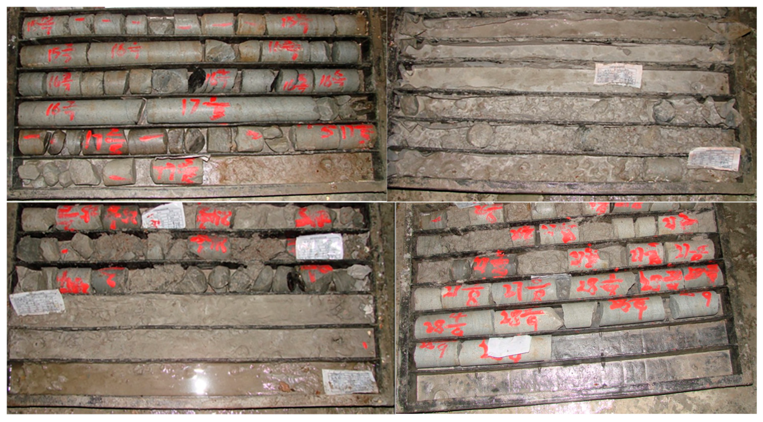
A month after grouting, the drilling of core samples was carried out at three holes in the HCW area, but no whole cores were obtained from the two holes in the HAC zone, and there were no acrylate gel core samples in the hole.
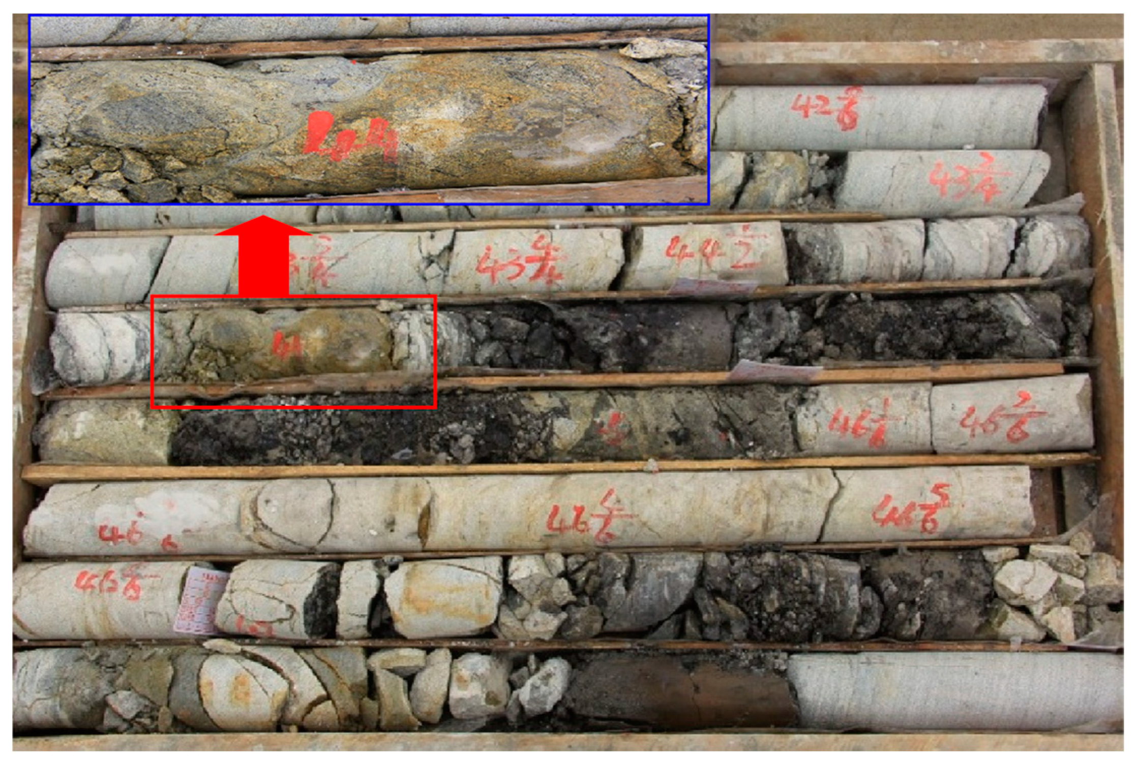
Figure 5 was a comparison of the core samples before and after the epoxy resin chemical grouting.
Figure 6 was a photograph of core samples one month after the epoxy resin chemical grouting, and, as shown in
Figure 6, the picture indicated by the arrow clearly displayed that the epoxy resin slurry leaked in the core sample. There were some grout veins of cement and epoxy in the core sample from the hole with epoxy resin chemical grouting, suggesting that the cement grouting played an important role in the larger porosity of the blocking cracks. The core samples of the microcracks in the flexural fracture zone were fully filled with the epoxy resin slurry.
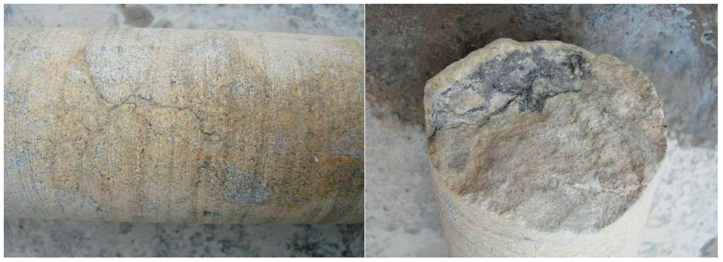
Figure 7 and
Figure 8 showed photographs of the core samples six months and one year after the epoxy grouting. Considerable amounts of yellow epoxy resin slurry filled the fractures of the argillaceous section core, with shaly sands and muddy debris cemented into the shape of a column. The silty sand was solid due to the yellow epoxy resin slurry, forming a rock-like material with high strength.
Based on the wet-milling cement and chemical compound grouting treatments used for the Three Gorges, the mechanism through which the cement–chemical compound grouting provided improvements was thought to be as follows: After plugging the larger cracks and voids via pressure grouting, a relatively closed area formed within a certain range. Then, the chemical grout wetted and infiltrated the microcracks areas that were difficult to reach; the cement grouting enhanced the integrity and strength of the flexural fracture zone to effectively restore the bearing function of the dam and improve its impermeability. Otherwise, a lot of research work and in situ tests have been carried out on the reinforcement of dam defects using grouting technology in the past two decades, and they all showed that it is necessary to inject cement grout first and then chemical grouting. Cement grout can fill in larger fissures, making the ground homogeneous and curing a relatively closed area within a certain range. Then, the chemical grouting material can enter and penetrate muddy cracks and structural fracture zones after a longer grouting time using a certain grouting pressure, thereby improving the overall mechanical properties of the treated objects.
In this study, the parameters of the experimental epoxy zone in the field test were better than those in the acrylate test area. This was mainly due to the use of CW510 epoxy resin grouting material and HAC grouting material in the indoor curing test of the clastic rock in the test area, and the compressive and tensile strength of the HAC mold specimens was weaker than that of the HCW mold specimens (
Table 1). The video results of the inspected holes after epoxy grouting are shown in
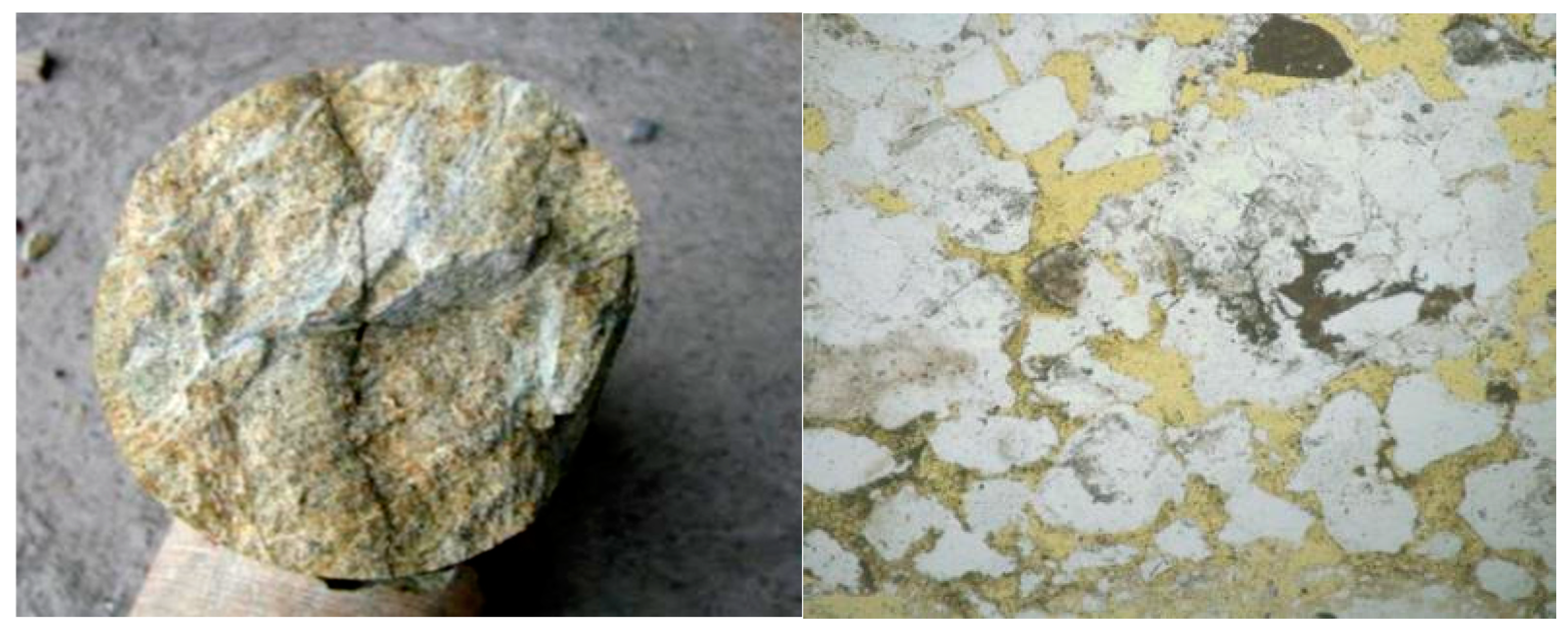
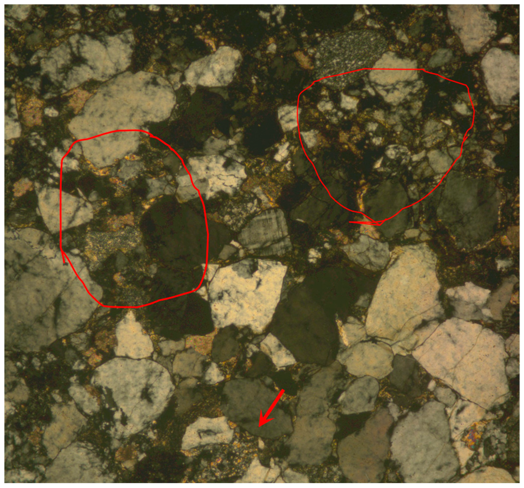
Figure 9. The epoxy resin entered the fine voids, fissures, clayey soil, shaly sand, as well as the silty sand and bonded these formations together, significantly improving the overall mechanical properties in the treated zone. In addition, the polarized light micrographs of the inspected holes after epoxy grouting also showed a clear yellow grouting material (
Figure 10). Moreover, it can be clearly seen from the red circle and arrow pointing in
Figure 10 that the epoxy resin slurry played a bonding role in the broken core sample.


