Article

Parametric Optimization of Concentrated Photovoltaic-Phase Change Material as a Thermal Energy Source for Buildings

1
Department of Architectural Engineering, College of Engineering, United Arab Emirates University, Al Ain P.O. Box 15551, United Arab Emirates
2
School of Engineering and Physical Sciences, Heriot Watt University, Dubai Campus, Dubai P.O. Box 501745, United Arab Emirates
3
Department of Electrical and Electronics Engineering, School of Engineering, Al Maaref University, Beirut P.O. Box 5078/25, Lebanon
4
Department of Electrical Engineering, College of Engineering, United Arab Emirates University, Al Ain P.O. Box 15551, United Arab Emirates
*
Author to whom correspondence should be addressed.
Buildings 2025, 15(3), 327; https://doi.org/10.3390/buildings15030327
Submission received: 13 July 2024 / Revised: 14 October 2024 / Accepted: 11 November 2024 / Published: 22 January 2025

Abstract

A concentrated photovoltaic system is evaluated as a thermal energy source employing phase change material to meet the domestic water heating demand. A paraffin wax-based phase change material is selected with a 58 °C melting point to store enough thermal energy to match the hot water demand in the buildings. The energy performance of the concentrated photovoltaics containing phase change materials is compared to that of the reference to determine the increased energy outputs due to the heat removal by the material. The concentrated photovoltaics-phase change material achieved 30% higher energy output compared to the reference concentrated photovoltaic, thus providing a strong justification for the improved thermal management design. An enthalpy-based thermal model is developed to compare the experimental results with model predictions, confirming a reasonable agreement between the results. The model is used determine the optimum melting point and container size for different phase change materials under different radiation concentrations for the hot climate of the United Arab Emirates.

1. Introduction

The photovoltaic panels produce more energy when the radiation intensity on the panels increases; however, the increased radiation also increases the temperature of the panel. The increased panel temperature reduces power output and panel life due to the cell degradation [1] caused by the excessive heat associated with solar radiation. In order to mitigate temperature-based failures in PV systems, it is crucial to remove heat effectively from the panels to keep them at lower temperatures [2]. In order to remove the panel heat, a latent heat removal method was applied through the use of the phase change material (PCM) housed in an aluminum container and attached to the back of the PV cell [3]. The heat transfer was augmented by applying various internal fin arrangements that improved the PCM thermal conductivity and melting/solidification rates [4]. The improved heat transfer rates helped maintain the PV at lower temperatures, which eventually increased the power produced from the PV cells [5]. Building on this work, the authors applied the scheme on a true PV cell with an arrangement named the photovoltaics-phase change materials thermal management system (PV-PCM). The system was tested through simulated solar radiation indoors produced by a solar simulator, concluding that the inclusion of the PCM reduced the PV temperature significantly [6]. The authors tested the PV-PCM system on a large-scale PV panel outdoors, utilizing eutectic fatty acid, capric-palmitic acid and CaCl2⋅6H2O as PCMs sourced from sigma Aldrich, Darmstadt, Germany. The PV-PCM system performed better in hot and stable weather conditions in Vehari compared to the cooled and variable ambient conditions in Dublin with a peak time temperature drop of 21 °C and power gain of 13% [7]. Comparatively, CaCl2⋅6H2O achieved up to 4 °C higher cooling and 3% increased power production than the counterpart capric–palmitic acid at both sites. The research suggested that the application of the PCM in different climates faces unique challenges and requires a specifically tailored melting point and containment size to meet the contextual requirements [8].
Learning from the previous research, the authors designed the PV-PCM system specifically for the extremely hot climate of the UAE with a specific melting point of 40 °C and a container depth of 6 cm, representing the PCM thickness. The system was continuously tested for one year outdoors to study the durability and performance of the system over a long time. The PV-PCM system achieved a temperature drop of 10.5 °C with an increase in electrical yield of 5.9% yearly [9]. The PV-PCM system was integrated into buildings for cooling building-integrated photovoltaics (BIPV) and shielding the building from excessive heat gain [10]. A microencapsulated PCM integrated at the back of the BIPV was numerically tested for the BIPV, showing a maximum of 5 °C drop in temperature in summer. Due to the lower temperature drop, the microencapsulated PCM was less effective in cooling PVs, which was mainly due to the heat resistance of the insulating encapsulated materials and a limited amount of PCM in the microencapsulation process [11]. In a separate simulation employing the PCM in the PV, up to 3% extra energy was gained annually for Utrecht (the Netherlands) and Malaga (Spain). The energy gain was found insufficient to economically justify the payback of the cost incurred on the system within an acceptable time [12]. The PCM has been experimentally evaluated to cool the PV to increase its energy production in Lisbon, Portugal, during winter. The PV exhibited maximum efficiency of up to 12% [13]. In a separate experimental study, heat stored at the back of the PV was used to heat domestic water in the UAE. The proposed system achieved a 1.3% increase in PV electrical conversion efficiency and a recovery of ~41% of the thermal energy calculated based on incident solar radiation [14]. Most of the research concluded that the PCMs performance is insignificant in extracting heat from non-concentrated PV panels due to low temperature mostly not in the range of application [15]. The CPV-PCM can provide significantly higher thermal energy; however, it suffers from the re-solidification of PCM in hot climates [6,14] and lower heat recovery rates [16]. Extensive reviews on PCM-based PV thermal energy recovery systems concluded that the proposed technology could be finically attractive provided the stored thermal energy is utilized effectively [16,17,18]. A concentrated photovoltaics (CPV) requires an essential thermal management system as the CPV is exposed to substantially higher temperatures that render substantial power loss and rapid cell degradation [19]. Additionally, high-temperature heat can be stored and utilized effectively in several processes [20,21,22]. Applying a PCM in a CPV was tested in the hot climate of Delhi, India, using 58 °C melting point paraffin wax with a metal matrix. A 16 °C temperature reduction with 1.55 times increased power output was recorded at the solar radiation intensity of 1982 W/m2. The PCM maintained similar performance over repeated cycles, showing complete PCM melting during the daytime and solidification through natural cooling at nighttime [23]. Parabolic concentrators employing PCM RT27 were tested at an incident solar radiation of 672 W/m2 and incident angle of 0°, achieving a drop of up to 18 °C in PV temperature [24]. A thermal model predicted the optimal inclination of CPV-PCM being 45° in Egypt [25]. The PCM cooled CPV achieved 15% higher total (electrical + thermal) energy yield compared to water cooled CPV in Macau [26]. The previous studies investigated PCM applications for PV cooling in a general context [27,28,29] without addressing the unique challenges posed by extremely hot climates, which may cause incomplete PCM solidification at night due to high nighttime temperatures.
Several studies have established that the application of PCM for PV cooling is highly contextual and needs to be optimized for specific environmental factors. A comprehensive review on the use of PCMs for PV cooling applications has suggested that the PCM properties need to be optimized for large-scale applications along with careful selection and sizing of the PCM for specific climates responding to unique environmental factors [30]. A review on the PCM selection criteria for PV thermal management applications scoped around the phase transition temperature, latent heat absorption and thermal conductivity suggested that the PCM needs to be optimized depending on the nano inclusions, fins arrangement, concentration ratio and the heat extraction mechanism for optimal PV-PCM performance [31]. In an attempt to optimize PCM application for PV cooling, inclination angles ranging from 30° to 60° were evaluated, reporting a maximum temperature drop of 13.1 °C with a power gain of 6.85% and an inclination angle of 30 °C in Islamabad, Pakistan [32]. An indoor study investigated the impact of PCM cooling on PV cells in the absence of wind flow as an influencing parameter and concluded that PCM inclusion retards PV heating and cooling, thus reducing thermal stress on the cell and enhancing the cell life [33]. A numerical model was deployed to optimize the selection of the PCM melting point ranging from 21 to 44 °C employing a commercial grade PCM RT. It concluded that for Islamabad, Pakistan, a climate PCM with a 21 °C melting point achieved the optimal performance [34]. A recent study comprehensively reviewed the state of the art of PCM applications for PV cooling and concluded that the right choice of enhanced thermal conductivity through nanocomposites, while the fins arrangement in the PCM and the integration of the PV-PCM system to existing cooling/heating systems can materialize the applications of the PCM for PV cooling [35].
The present study aims to test a CPV-PCM system specifically suitable for the UAE’s hot environment starting with PCM melting point optimization until storage capacity utilization. The thermal energy stored in a phase change material is calculated by assessing temperature variations and phase transitions using heat capacity and latent heat equations. The study involves an experimentally validated model developed by the authors and explained in a previous article [9] to predict the system response under various conditions.

2. Materials and Methods

The PCM was filled in a metal container having internal fins attached to the back side of the CPV. A thermal model of the CPV-PCM was developed and validated with three days of experimental data conducted in 21–23 July in Al Ain, UAE. After validation, the thermal model was utilized to predict the required PCM container size at different intensities, the suitable PCM melting point for a typical summer day in UAE, and the effective amount of different PCMs for the proposed CPV cooling.

2.1. Experimental Setup

Four photovoltaic panels of 10 W each were installed at an inclination of 24° south in Al Ain, UAE. A Fresnel lens concentrator of 1 m2 aperture area fabricated from PMMA with a focal length of 800 mm was deployed to provide concentrated radiation onto the panel surface. Panel 1 was kept static under regular radiation, panel 2 was tracked on two axes under 0 concentration, panel 3 was tracked under concentrated radiation and panel 4 was tracked under concentrated radiation with a PCM attached at the back. The Fresnel lens created a 36 cm diameter concentrated radiation covering two PV surfaces. The PCM was contained in a metallic containment having internal fins insulated with 2.5 cm fiber glass and a thermal conductivity of 0.039 Wm−1K−1 [36] to reduce heat loss to the ambient. The heat was stored in the PCM at the back of the CPV, thus making the CPV-PCM system outfitted with a metallic heat exchanger fabricated out of 1 cm external diameter stainless steel pipes. The heat exchanger was connected to the water loop to circulate through the PCM and remove the heat. The CPV-PCM unit was measured 25 cm × 25 cm as the aperture area and had a PV panel fixed to the metallic container of the same aperture area with 40 cm depth to store the PCM. The CPV-PCM weighed 10 kgs when empty and 36 kg when filled with salt hydrate. The CPV-PCM system was connected to a water storage tank with a capacity of 250 L. The heat was extracted by water circulation through the PCM.
Several calibrated K-type thermocouples with an accuracy of ±1.5 °C (Class 1 tolerance) were embedded to measure the temperature of the PV surfaces, PCM, water in the storage tank and ambient. The solar radiation intensity was measured through pyranometers with a sensitivity of 0.20 mV per W/m2 and accuracy of ±5% [37]. The data were logged every 5 min through the Compact DAQ sourced from National Instrument (NI) [38], Austin, TX, USA. The whole setup is shown in the Figure 1.
The thermophysical properties of the materials used in the experiment are listed in Table 1.
The material properties of the enclosure materials are summarized in Table 2.

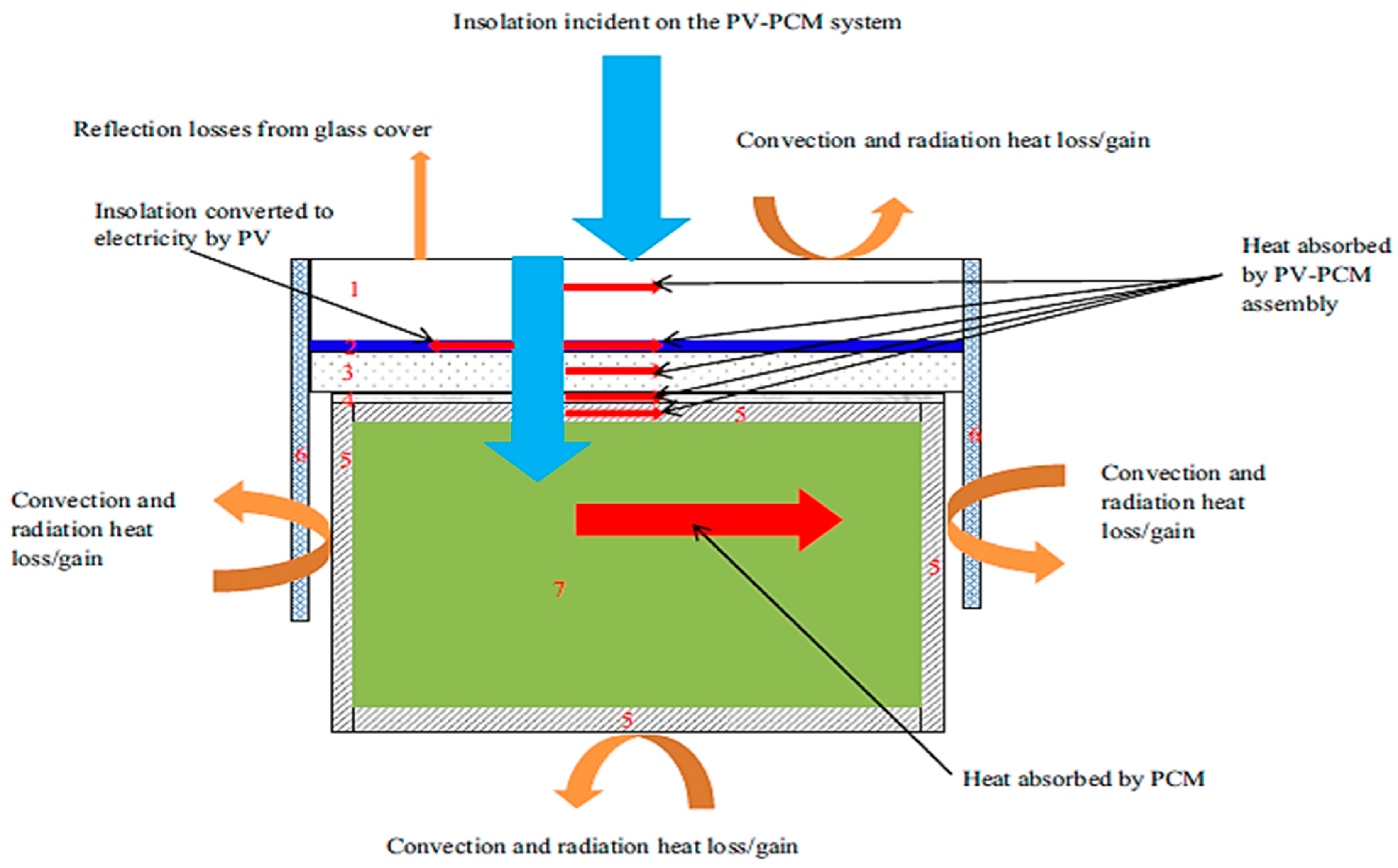
2.2. Numerical Model
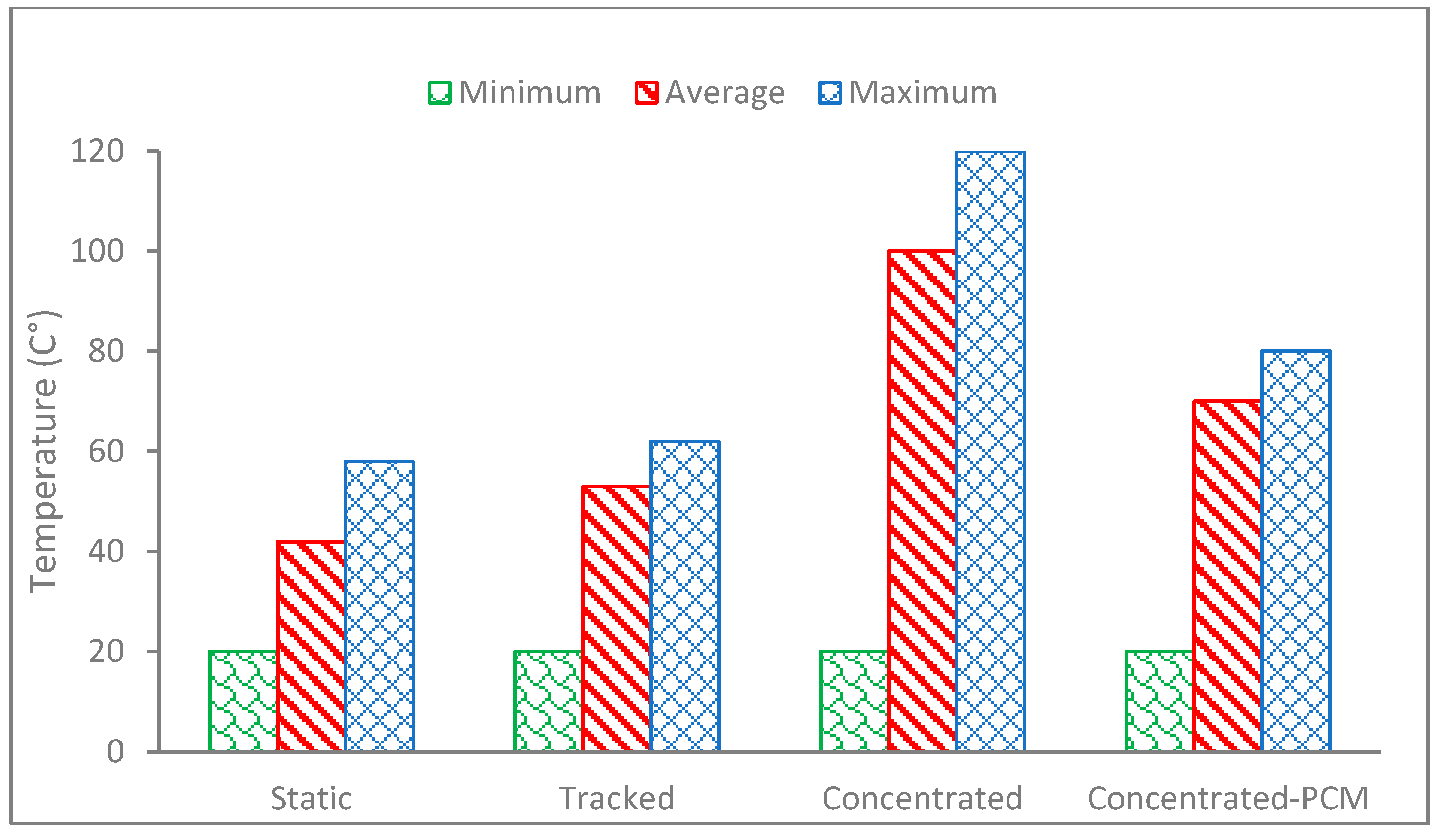
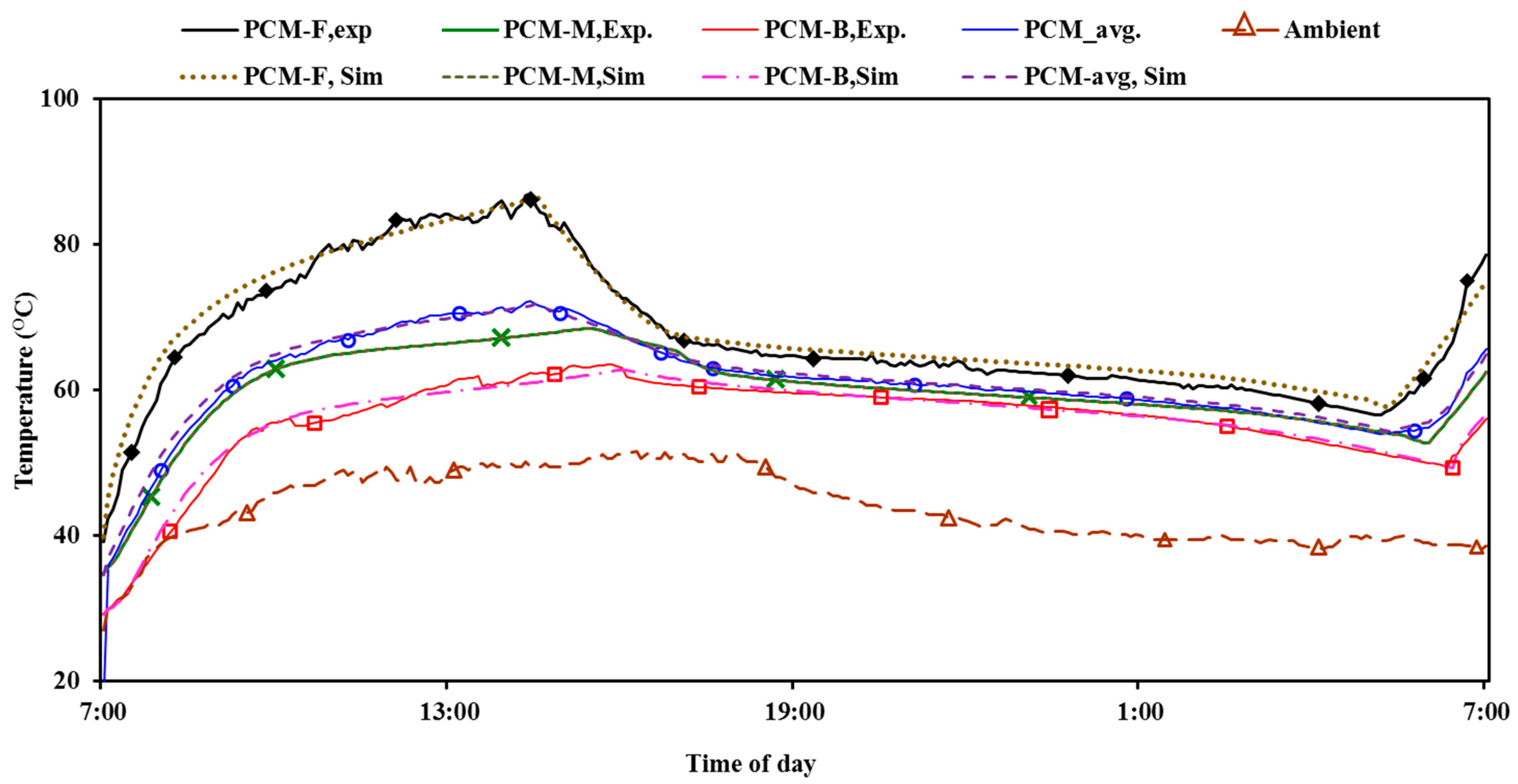
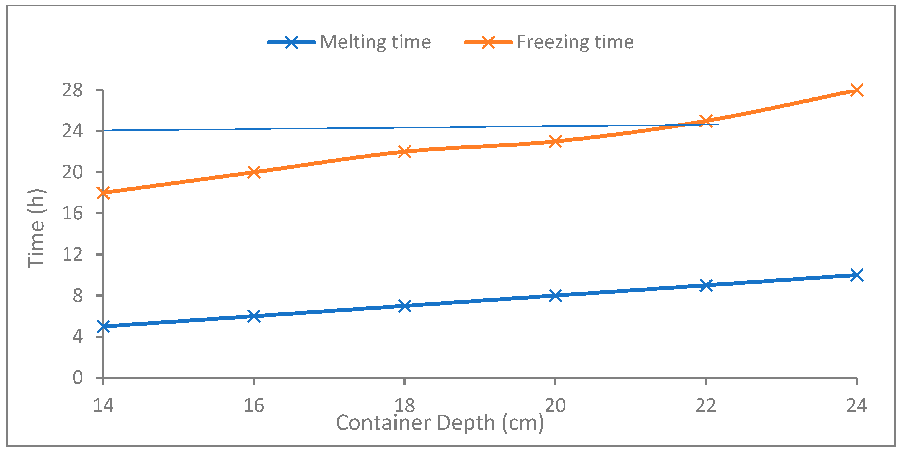
A thermal model for the latent heat storage and release behind the CPV was developed previously by authors and explained in a previously published article in [9]. The model was solved using a commercial software package, Ansys Fluent R2 (20.2). The model predicts the transient temperature distribution within a two-dimensional region in the CPV-PCM system for different G, Tamb, and convective and radiative heat transfer boundary conditions. The simulations were carried out using the summer weather conditions of Al Ain city in the UAE. The simulation model is validated with the experimental results, and the validated model is employed to predict the parametric influences on the performance of the CPV-PCM system. The results of the CPV only and the PV–PCM are compared as discussed in the sections. The schematics of the numerical setup is shown in Figure 2.

3. Discussion

The solar radiation intensity received by the static PV panel under no concentration, tracked PV panel under no concentration, and tracked PV panel under concentration (CPV) is shown in Figure 3.
The static PV and tracked PV under no concentration received a peak radiation intensity of 760 w/m2, while the tracked CPV received the peak radiation intensity of 2200 W/m2 at 13:00. It is evident that the tracked CPV received around three times more radiation than the static and tracked PV and hence was expected to undergo higher temperatures that would require cooling for safe operation.
Figure 4 shows the total solar energy gained by the three PV systems for the 2nd day of the test period, 22 July in Al Ain, UAE. It is very obvious that the static PV received the lowest energy around 5 kWh/m2, which increased to 6.7 kWh/m2 for the tracked PV showing 1.7 kWh/m2 (32%) gain due to tracking. Eventually, the CPV received a significantly higher energy level of 16 kWh/m2, which was almost three times more than the static PV. It reflects a significantly higher level of thermal energy density available at the CPV that would be worth exploiting. Figure 5 shows the minimum, average and maximum temperature rise of the three PVs under their respective test conditions measured in Al Ain for 2nd day of test duration on 22 July using paraffin wax with a melting point of 58 °C.
In order to make a fair comparison, all the PVs started with the same initial minimum temperature of 20 °C (green bar in Figure 5). It can be noted that the CPV (Concentrated-PCM in Figure 5) achieved the highest temperature of 120 °C at peak, which was significantly higher than the peak temperature of the static and tracked PVs of 60 °C. It is noted that the peak temperature of the CPV dropped to 80 °C when paraffin wax RT 60 with a melting point of 58 °C was used as the PCM added at the back of the CPV (Concentrated-PCM in Figure 5), showing a 40 °C temperature drop due to cooling produced by the melting PCM. A similar trend is observed in the average temperature (red bar in Figure 5) with slightly lower temperatures (in the range of 5–10 °C) of the respective PV and CPV. The temperature drop is caused by the melting PCM which removes heat by absorbing it as latent heat of fusion. It is therefore established that a significant temperature drop as well as heat storage can be achieved by the integration of a PCM into the CPV, which can be utilized for domestic water heating applications.
In order to evaluate the parametric influences of the PCM to control CPV temperature and optimize the CPV-PCM design, the thermal model was validated with measured temperatures at various locations of the PCM during the phase change process, as shown in Figure 6.
The temperatures are compared at the front layer (3 cm inside PCM from front), middle layer, back layer (3 cm inside PCM from back) and average temperatures. Figure 6 shows that the temperature propagation curve is generally similar at all PCM locations both in trend and magnitude. The statistical analysis of the measured data showed that standard deviations of 2.5%, 1.3%, and 1.1% were recorded at the front PCM layer, middle PCM layer, and back PCM layer, respectively. Since the deviation is within an acceptable range below 5%, the model is deemed to be validated.
The validated model is used to predict an optimal PCM amount (represented by container size) that can effectively melt and cool the CPV during the heating cycle and can return to solid form during the cooling cycle within a given time frame. The natural diurnal cycle demands the PCM to melt during daytime by thermal energy available at the back of the CPV and solidify at nighttime by dissipating heat to the cooler ambient to mimic the natural cycle.
Figure 7 presents the time required by the PCM to completely melt by the heat available at the CPV at a 3× optical concentration ratio during daytime (blue line) and the time required to return the PCM back to solid form by natural cooling at nighttime. The PCM container depths ranging from 14 to 24 cm representing the amount of PCM are considered for the simulations. It can be observed that the PCM with up to 20 cm thickness completed melting within 8 h and re-solidified within 22 h (keeping 2 h safety factor), indicating the maximum applicable PCM thickness.
The validated numerical model was used to predict the optimal amount of PCM required for various optical concentration ratios (OCRs) of solar radiation representing thermal energy available at the CPV ranging from 1 to 12. The PCM container width was kept fixed in line with the aperture area of the CPV (25 cm × 36 cm), while the depth was varied to represent the varying volume of the PCM contained in the enclosure. The PCM amount that melted completely within the daytime (10 h) and re-solidified overnight within the total time duration of 22 h (keeping 2 h as safety factor) is considered optimal, as shown in Figure 8.
The predicted container depth for the OCR 1 is 9 cm, and it almost doubled to 20 cm at OCR 2. The container size kept increasing but with a decreasing gradient as the OCR increased. The increase in container depth became negligible after reaching 60 cm at OCR 12, showing a ceiling in the container depth.
Selecting an optimum PCM melting point suited to the ambient conditions is an important aspect of ensuring PCM melting/solidification within the required time, which dictates PCM performance as a temperature regulator. A range of PCM melting points from 35 °C to 65 °C is simulated, and the associated melting/solidification fraction is predicted to determine the PCM melting/solidification character, as shown in Figure 9.
Figure 9 indicates that the PCM with lower melting points of 35 °C, 40 °C, and 45 °C melted entirely in less than 10 h. However, these lower melting points of PCM need more than 20 h to completely solidify due to the high nighttime ambient temperature in summer (July). Less heat is released to the ambient, resulting in partial solidification of the material within 24 h (one day), affecting the material’s cooling performance the next day as well.
On the other hand, with a high melting point (65 °C), the PCM takes a long time (more than 10 h) to completely melt, which is not applicable in the UAE weather, where daytime is limited to 9 h. Additionally, the PCM with lower melting points achieved higher temperature drops (both maximum and average), as shown in Figure 10.
This result emphasizes that selecting a PCM with a lower melting point would allow the PCM to melt within the daytime, and a PCM melting point higher than the nighttime temperature will allow the material to solidify fully at night. From that perspective, using the PCM with a melting point between 55 and 60 °C will have the best melting/solidification performance within 24 h, achieving a maximum and average temperature drop of (36–35) °C and (25–23) °C, respectively (presented in Figure 10).
Different PCM types, namely waxes (paraffin), fatty acids (palmitic acid), and salt hydrates (SP salt), were investigated to determine the material-specific PCM amount that can completely melt and solidify within the diurnal time frames, as shown in Figure 11.
Figure 11 shows the amount of different PCMs—namely paraffin, palmitic acid and salt hydrate—required to complete the melting and solidification cycle within 22 h of thermal energy gain to represent a typical day and night cycle with a safety factor of 2 h. It can be noted that the lowest amount required to complete melting is exhibited by the salt hydrate, while the highest amount required is for paraffin. The findings are in line with the thermophysical properties of density, thermal conductivity, heat capacity and latent heat of fusion, which are highest for the salt hydrate and lowest for paraffin, as given in Table 1. The amount of PCM melting and freezing cycle in a given time is a strong inverse function of the latent heat of fusion and strong direct function of the thermal conductivity of the PCM. Since the latent heat of fusion of the salt hydrate is 1.6 times and 1.4 times that of the paraffin wax RT 60 and fatty acids, respectively, it tended to consume a lower amount of salt hydrate accordingly. On the contrary, the thermal conductivity of the salt hydrate is three times higher than that of both the paraffin wax RT 60 and fatty acids, which would tend to melt and freeze more of the PCM in the given time. The PCM amounts of 5 kg, 7 kg and 8 kg were completely melted and solidified in 22 h for the slat hydrate, fatty acids and paraffin wax. It shows that that SP is the most effective material that requires the minimum material as well as container space. However, salt hydrate possesses some thermal cyclic stability and chemical reactivity issues given that it may dehydrate with successive thermal cycles, corrode the metallic containers and also may undergo subcooling, which may require extra cooling to return it to solid form [34].
The CPV-PCM system comparison with the conventional solar water heater has been conducted by the authors and in a previously published article. The comparison revealed that the CPV-PCM system produces 1527 kWh/m2-day compared to FPC’s 1803 kWh/m2-day, yet the cost of production is 28% lower, making it a cheaper solution. Although the research is conducted in a hot climate with higher ambient temperature, the relevance can be made to cooler climates as well. Since the predominant heat source is concentrated radiation, not the ambient temperature, the desired temperature suitable for any type of climate can be achieved through the solar radiation concentration as a means of raising the temperature. The proposed CPV-PCM system can be added to the buildings with a higher water heating demand. The CPV-PCM system can be used as a water pre-heating system coupled with the auxiliary electrical or boiler-based heating system. The integration with the existing water supply lines requires an extension to the existing piping network to pass water through the CPV-PCM before it reaches the electrical heater/boiler similar to the integration scheme of any solar water heating system. The current article evaluated the system only for three days experimentally; a robust year-round performance needs to be evaluated to understand the PCM degradation over time, cooling and solidification rates in cooler weather as well as the performance degradation of the photovoltaic cells at elevated temperatures over a long time. The CPV-PCM system comparison with the conventional solar water heater has been conducted by the authors and in a previously published article. The CPV-PCM system produced 85% energy compared to a flat plate solar water heater on a Wh/m2 basis while being 28% cheaper based on production cost of the systems [42]. Since it is well known that the flat plate solar water heaters can meet the domestic hot water demand, it can be assumed that the CPV-PCM systems can be equally competitive.

4. Conclusions

A CPV-PCM system has been optimized for several parameters considering the diurnal melting and freezing of the PCM integrated at the back of the CPV for its effective thermal management through a validated thermal model. A paraffin-based PCM was experimentally evaluated to validate the thermal model. The validated thermal model is employed to predict the optimal parameters of the PCM and containment depth suitable for the PCM melting point, optimal concentration ratio, and the mass of PCM required to effectively complete the melting and freezing cycle within 20 h. It has been found that the melting point of the PCM in the enclosure with 20 cm depth was 55–60 °C. The PCM amount that completely melted and solidified within 22 h was found to be 5 kg, 7 kg and 8 kg for the salt hydrate, fatty acids and paraffin wax, respectively. The proposed CPV-PCM system reduced the CPV temperature by 50 °C, which was the most. However, this paper has the limitation of not investigating the long-term durability of the PCMs in real-time elongated exposure, which can be a subject of future research.

Author Contributions

Conceptualization by A.H. and M.N.; methodology, H.A.; software, S.A.; validation, A.H. and S.A.; formal analysis, M.H.; investigation, S.A., A.H.S. and A.H.; data curation, M.S.L., A.H. and M.N.; writing—review and editing, A.F. and M.S.L.; supervision, M.N.; project administration, M.H.; funding acquisition, A.H. and A.F. All authors have read and agreed to the published version of the manuscript.

Funding

This research was funded by the Emirates Center for National Water and Energy Centre (NWEC), United Arab Emirates University, grant number G00003312.

Data Availability Statement

Data will be made available on request.

Conflicts of Interest

The authors declare no conflicts of interest.

Nomenclature

PCMphase change material
PVphotovoltaics
BIPVbuilding integrated photovoltaics
CPVconcentrator photovoltaics
CPV-PCMconcentrated photovoltaic-phase change material system
ACPPVCasymmetric compound parabolic photovoltaic concentrators
THMtemperature history method
DTAdifferential thermal analysis
DSCdifferential scanning calorimetry
FFfill factor
Aarea (m2)
T P V PV panel temperature (°C)
T a m b ambient temperature (°C)
T L liquidus temperature (°C)
T S solidus temperature (°C)
T P C M PCM temperature (°C)
Gsolar radiation intensity (W/m2)
V o c open circuit voltage (V)
X i and X j unit vectors
Z c convection heat transfer (Wh)
Z r radiation heat transfer (Wh)
kthermal conductivity (W/m·K)
ρdensity (kg/m3)
ηenergy efficiency
Hconvection matric
Kconductivity matrix
Mmass matrix
cheat capacity
T ˙ the time derivative of temperature
q ^ irradiance or boundary flux matrix
Rradiation matrix
coreference heat capacity (solid)

References

  1. Saly, V.; Ruzinsky, M.; Redi, P. Indoor study and ageing tests of solar cells and encapsulations of experimental modules. In Proceedings of the 24th International Spring Seminar on Electronics Technology: Concurrent Engineering in Electronic Packaging, Calimanesti-Caciulata, Romania, 5–9 May 2001. [Google Scholar]
  2. Singh, P.; Ravindra, N.M. Temperature dependence of solar cell performance—An analysis. Sol. Energy Mater. Sol. Cells 2012, 101, 36–45. [Google Scholar] [CrossRef]
  3. Huang, M.J.; Eames, P.C.; Norton, B. Thermal regulation of building-integrated photovoltaics using phase change materials. Int. J. Heat Mass Transf. 2004, 47, 2715–2733. [Google Scholar] [CrossRef]
  4. Huang, M.J.; Eames, P.C.; Norton, B. Phase change materials for limiting temperature rise in building integrated photovoltaics. Sol. Energy 2006, 80, 1121–1130. [Google Scholar] [CrossRef]
  5. Huang, M.J.; Eames, P.C.; Norton, B.; Hewitt, N.J. Natural convection in an internally finned phase change material heat sink for the thermal management of photovoltaics. Sol. Energy Mater. Sol. Cells 2011, 95, 1598–1603. [Google Scholar] [CrossRef]
  6. Hasan, A.; McCormack, S.J.; Huang, M.J.; Norton, B. Evaluation of phase change materials for thermal regulation enhancement of building integrated photovoltaics. Sol. Energy 2010, 84, 1601–1612. [Google Scholar] [CrossRef]
  7. Hasan, A.; McCormack, S.J.; Huang, M.J.; Sarwar, J.; Norton, B. Increased photovoltaic performance through temperature regulation by phase change materials: Materials comparison in different climates. Sol. Energy 2015, 115, 264–276. [Google Scholar] [CrossRef]
  8. Hasan, A.; McCormack, S.J.; Huang, M.J.; Norton, B. Characterization of phase change materials for thermal control of photovoltaics using Differential Scanning Calorimetry and Temperature History Method. Energy Convers. Manag. 2014, 81, 322–329. [Google Scholar] [CrossRef]
  9. Hasan, A.; Sarwar, J.; Alnoman, H.; Abdelbaq, S. Yearly energy performance of a photovoltaic-phase change material (PV-PCM) system in the hot climate. Sol. Energy 2017, 146, 417–429. [Google Scholar] [CrossRef]
  10. Hasan, A.; Alnoman, H.; Rashid, Y. Energy and Buildings: Impact of integrated photovoltaic-phase change material system on building energy efficiency in hot climate. Energy Build. 2016, 130, 495–505. [Google Scholar] [CrossRef]
  11. Ho, C.J.; Tanuwijava, A.O.; Lai, C.M. Thermal and electrical performance of a BIPV integrated with a microencapsulated phase change material layer. Energy Build. 2012, 50, 331–338. [Google Scholar] [CrossRef]
  12. Hendricks, J.H.C.; Sark, W.G.J.H.M. Annual performance enhancement of building integrated photovoltaic modules by applying phase change materials. Prog. Photovolt. 2013, 21, 620–630. [Google Scholar] [CrossRef]
  13. Aelenei, L.; Pereira, R.; Gonçalves, H.; Athienitis, A. Thermal performance of a hybrid BIPV-PCM: Modeling. Des. Exp. Investig. Energy Proc. 2014, 48, 474–483. [Google Scholar] [CrossRef]
  14. Hasan, A.; Alnoman, H.; Shah, A.H. Energy Efficiency Enhancement of Photovoltaics by Phase Change Materials through Thermal Energy Recovery. Energies 2016, 9, 782. [Google Scholar] [CrossRef]
  15. Bahaidarah, H.M.S.; Baloch, A.A.B.; Gandhidasan, P. Uniform cooling of photovoltaic panels: A review. Renew. Sustain. Energy Rev. 2016, 57, 1520–1544. [Google Scholar] [CrossRef]
  16. Browne, M.C.; Norton, B.; McCormack, S.J. Phase change materials for photovoltaic thermal management. Renew. Sustain. Energy Rev. 2015, 47, 762–782. [Google Scholar] [CrossRef]
  17. Ma, T.; Yang, H.; Zhang, Y.; Lu, L.; Wang, X. Using phase change materials in photovoltaic systems for thermal regulation and electrical efficiency improvement: A review and outlook Renew. Sustain. Energy Rev. 2015, 43, 1273–1284. [Google Scholar] [CrossRef]
  18. Islam, M.M.; Pandey, A.K.; Hasanuzzaman, M.; Rahim, N.A. Recent progresses and achievements in photovoltaic-phase change material technology: A review with special treatment on photovoltaic thermal-phase change material systems. Energy Convers. Manag. 2016, 126, 177–204. [Google Scholar] [CrossRef]
  19. Royne, A.; Dey, C.J.; Mills, D.R. Cooling of photovoltaic cells under concentrated illumination: A critical review. Sol. Energy Mater. Sol. Cells 2005, 86, 451–483. [Google Scholar] [CrossRef]
  20. Du, B.; Hu, E.; Kolhe, M. Performance analysis of water cooled concentrated photovoltaic (CPV) system. Renew. Sustain. Energy Rev. 2012, 16, 6732–6736. [Google Scholar] [CrossRef]
  21. Hasan, A.; Sarwar, J.; Shah, A.H. Concentrated photovoltaic: A review of thermal aspects, challenges and opportunities. Renew. Sustain. Energy Rev. 2018, 94, 835–852. [Google Scholar] [CrossRef]
  22. D’Orazio, M.; Di Perna, C.; Di Giuseppe, E. Performance assessment of different roof integrated photovoltaic modules under Mediterranean Climate. Energy Procedia 2013, 42, 183–192. [Google Scholar] [CrossRef]
  23. Maiti, S.; Banerjee, S.; Vyas, K.; Patel, P.; Ghosh, P.K. Self regulation of photovoltaic module temperature in V-trough using a metal-wax composite phase change matrix. Sol. Energy 2011, 85, 1805–1816. [Google Scholar] [CrossRef]
  24. Wu, Y.; Eames, P. Experimental characterization of an asymmetric compound parabolic PV concentrator complied with a phase change material. In Proceedings of the 7th Photovoltaic Science, Applications and Technology Conference, Heriot-Watt University, Edinburgh, UK, 6–8 April 2011. [Google Scholar]
  25. Emam, M.; Ookawara, S.; Ahmed, M. Performance study and analysis of an inclined concentrated photovoltaic-phase change material system. Sol. Energy 2017, 150, 229–245. [Google Scholar] [CrossRef]
  26. Su, Y.; Zhang, Y.; Shu, L. Experimental study of using phase change material cooling in a solar tracking concentrated photovoltaic-thermal system. Sol. Energy 2018, 159, 777–785. [Google Scholar] [CrossRef]
  27. Sharma, S.; Tahir, A.; Reddy, K.S.; Tapas, K.M. Performance enhancement of a Building-Integrated Concentrating Photovoltaic system using phase change material. Sol. Energy Mater. Sol. Cells 2016, 149, 29–39. [Google Scholar] [CrossRef]
  28. Sarwar, J. Experimental and Numerical Investigation of Thermal Regulation of Photovoltaic and Concentrated Photovoltaic Using Phase Change Materials. Ph.D. Thesis, Dublin Institute of Technology, Dublin, Ireland, 2012. [Google Scholar]
  29. Omaraa, E.; Saman, W.; Bruno, F.; Citation, M.L. Modified T-history method for measuring thermophysical properties of phase change materials at high temperature. AIP Conf. Proc. 2017, 1850, 080020. [Google Scholar] [CrossRef]
  30. Sharma, N.K.; Gaur, M.K.; Malvi, C.S. Application of phase change materials for cooling of solar photovoltaic panels: A review. Mater. Today 2021, 47 Pt 19, 6759–6765. [Google Scholar] [CrossRef]
  31. Sivashankar, M.; Selvam, C.; Manikandan, S. A review on the selection of phase change materials for photovoltaic thermal management. IOP Conf. Ser. Mater. Sci. Eng. 2021, 1130, 012026. [Google Scholar] [CrossRef]
  32. Hussain, B.; Waseem, H.; Hasnain, M.F.U.; Irfan, M. Phase Change Material for the Cooling of Solar Panels—An Experimental Study. Eng. Proc. 2023, 45, 43. [Google Scholar] [CrossRef]
  33. Xu, Z.; Kong, Q.; Qu, H.; Wang, C. Cooling characteristics of solar photovoltaic panels based on phase change materials. Case Stud. Therm. Eng. 2023, 41, 102667. [Google Scholar] [CrossRef]
  34. Durez, A.; Ali, M.; Waqas, A.; Nazir, K.; Kumarasamy, S. Modelling and optimization of phase change materials (PCM)-based passive cooling of solar PV panels in multi climate conditions. Front. Energy Res. 2023, 11, 1121138. [Google Scholar] [CrossRef]
  35. El Kassar, R.; Al Takash, A.; Faraj, J.; Khaled, M.; Ramadan, H.S. Phase change materials for enhanced photovoltaic panels performance: A comprehensive review and critical analysis. Energy Built Environ. 2024; in press. [Google Scholar] [CrossRef]
  36. Osking, L.; Glass Wool Insulation Business Co., Ltd. Available online: http://www.osking-insulation.com/ (accessed on 21 August 2024).
  37. Apogee Instruments. SP-110: Self-Powered Pyranometer. Available online: https://www.apogeeinstruments.com/sp-110-ss-self-powered-pyranometer/ (accessed on 21 August 2024).
  38. National Instruments. Compact DAQ. 2016. Available online: http://www.ni.com/data-acquisition/compactdaq/ (accessed on 7 August 2024).
  39. Rubitherma. Available online: https://www.rubitherm.eu/en/productcategory/organische-pcm-rt (accessed on 2 September 2024).
  40. Rubitherm. Available online: https://www.rubitherm.eu/en/productcategory/anorganische-pcm-sp (accessed on 2 September 2024).
  41. Aalco: The UK’s Largest Independent Multi-Metals Stockholder. Available online: http://www.aalco.co.uk/ (accessed on 21 August 2024).
  42. Aoul, K.T.; Hassan, A.; Shah, A.H.; Riaz, H. Energy performance comparison of concentrated photovoltaic—Phase change material thermal (CPV-PCM/T) system with flat plate collector (FPC). Sol. Energy 2018, 176, 453–464. [Google Scholar] [CrossRef]
Figure 1. Experimental setup of the CPV-PCM system.
Buildings 15 00327 g001
Figure 2. The schematics of the numerical setup showing the heat transfer boundaries in the control domain.
Buildings 15 00327 g002
Figure 3. Solar radiation intensity received at the front surface of static PV, tracked PV, and tracked CPV measured for three days in 21–23 July at UAE University Al Ain.
Buildings 15 00327 g003
Figure 4. The total energy gain per day by the static PV, PV tracked and CPV measured on the 2nd day of test duration, 22nd July representative of extremely hot weather in Al Ain, UAE.
Buildings 15 00327 g004
Figure 5. The temperature rise of the static PV, tracked PV, CPV and CPV-PCM systems using paraffin wax with a melting point of 58 °C measured on the 2nd day of test duration, 22 July representative of extremely hot weather in Al Ain, UAE.
Buildings 15 00327 g005
Figure 6. Comparison of measured temperatures of the PCM, paraffin wax, RT-60, with the temperatures predicted by the model at the front layer, middle layer, and back layer of the melting PCM for a typical summer day in Al Ain, UAE employing the onsite measured weather data.
Buildings 15 00327 g006
Figure 7. Time required by the solid PCM to completely melt by the solar thermal energy available at CPV (blue line) and return to solid form (orange line) by heat dissipation to cooler ambient for various container depths.
Buildings 15 00327 g007
Figure 8. The optimal amount of PCM required under optical concentration ratios (OCRs).
Buildings 15 00327 g008
Figure 9. The numerically predicted melting fraction as a function of time of PCM (paraffin wax, RT 60) at various melting points between 35 °C and 65 °C to evaluate the time taken to complete melting and solidification cycle.
Buildings 15 00327 g009
Figure 10. The numerically predicted maximum and average temperature drop (°C) achievable by PCM with different melting points from 35 °C to 65 °C.
Buildings 15 00327 g010
Figure 11. The optimal amount of various PCMs under optical concentration ratio (OCR) of 3.
Buildings 15 00327 g011
Table 1. Thermophysical properties of PCM, metallic and bonding materials used in the experiments in solid state sourced from Rubitherm Technologies, GmbH, Berlin, Germany.
PCMMelting Range (°C)Congealing Range (°C)Latent Heat (kJ/kg)Specific Heat Capacity (kJ/kg·K)Heat Conductivity (W/m·K)Density (kg/L)Volume ExpansionFlash Point (°C)
RT60 [39] 55–6161–55160 20.20.8812.5%>200
SP-58 [40]56–5956–5425020.61.38%NA
Fatty Acid [41] 58–6462–561852.20.20.8510%230
Table 2. Thermophysical properties metallic and bonding materials used in the experiments in solid state sourced from local market, Al Ain, UAE.
PropertiesMelting Point (°C)Congealing Point (°C)Latent Heat (kJ/kg)Specific Heat Capacity (kJ/kg·K)Heat Conductivity (W/m·K)Density (kg/L)Volume ExpansionFlash Point (°C)
Aluminum [42] 650NANA0.912222.7124 × 10−6/KNA
Epoxy Resin 130NANANA1.262.0934 × 10−6/K350
Disclaimer/Publisher’s Note: The statements, opinions and data contained in all publications are solely those of the individual author(s) and contributor(s) and not of MDPI and/or the editor(s). MDPI and/or the editor(s) disclaim responsibility for any injury to people or property resulting from any ideas, methods, instructions or products referred to in the content.

