1. Introduction
The seismic failures observed during the 1994 Northridge and 1995 Kobe earthquakes exposed significant deficiencies in the seismic performance of steel moment-resisting frames (MRFs), particularly at the beam-to-column connection zones. Post-earthquake assessments, such as those conducted by FEMA [
1], attributed many structural collapses to brittle fractures in welded joints. These observations demonstrated that conventional MRF connections lacked the ductility and energy absorption capacity necessary to accommodate intense seismic demands. Consequently, considerable efforts have been devoted over the past two decades to improving the seismic resilience of steel connections, either by enhancing their ductility or by shifting damage away from highly stressed regions such as the column face [
2,
3].
A major advancement in this area was the proposal by Plumier [
4] to intentionally weaken beam sections to promote plastic hinge formation away from the column interface. This led to the development of two main strategies: reduced beam section (RBS)and reduced web section (RWS) connections. In the RBS approach, the beam flanges are trimmed to redistribute internal forces [
5,
6,
7,
8,
9,
10,
11,
12,
13,
14], while the RWS technique introduces perforations into the web—often based on Vierendeel action principles—to create a deliberate weak zone. Both approaches aim to relocate the plastic hinge to more favourable regions, reduce stress concentrations, and improve overall deformation capacity.
Extensive research has been conducted to refine the RWS concept and evaluate its behaviour under seismic loading. Experimental programmes, numerical simulations, and field applications have collectively demonstrated the potential of RWS connections to enhance ductility and energy dissipation. Configurations involving parallel web voids have been shown to shift plastic hinges away from critical weld areas and reduce local stress demands [
7]. Other variants, such as channel-type connectors bolted through rectangular openings [
15,
16,
17] and cellular beam configurations [
18,
19], have further contributed to the optimization of seismic performance. Studies by Sofias et al. [
20] and Konstantinos and Papadopoulos [
12] confirmed that geometric modifications in the beam web significantly influence plastic hinge formation, local stability, and rotational behaviour under cyclic loading.
Despite these improvements, the RWS method presents several limitations. Achieving sufficient weakening often requires large web openings, which can compromise the residual cross-section and lead to premature failure due to combined shear-flexure demands in the remaining T-shaped segments [
7,
13]. Additionally, issues such as local and lateral-torsional buckling, along with strength degradation at high rotation levels, remain persistent concerns (FEMA (2020)). Researchers have attempted to address these issues through dimensional limitations [
15,
21], web stiffeners [
22,
23] and corrugated infill plates [
14,
24,
25]; however, these solutions often introduce added fabrication complexity and cost, which may hinder their practical implementation.
Recent studies on moment-resisting frame connections have shown that incorporating replaceable energy-dissipating elements can effectively concentrate inelastic deformation in sacrificial components, maintain overall stiffness, and allow for post-earthquake repair, providing a foundation for the design of the proposed sleeve fuse system [
26,
27]. In this context, a modular steel sleeve fuse system has also been proposed [
28,
29] to improve the rotational capacity and ductility of bolted endplate connections. The system is designed to act as a sacrificial element that yields under seismic demands while preserving the integrity of the primary structural components. By inserting a curved-wall steel sleeve between the bolt and endplate assembly, the design concentrates inelastic deformation within the sleeve, which can be easily replaced after an earthquake. This method requires no welding or significant structural modification, making it especially suitable for retrofit applications. Experimental and numerical studies by Shaheen et al. [
30,
31] demonstrated that the inclusion of the sleeve substantially improved the connection’s performance in ductility and energy dissipation relative to standard configurations, without compromising initial stiffness or strength.
Unlike RWS and RBS, which force plastic hinging through intentional weakening of beam flanges or webs, the proposed sleeve fuse introduces a replaceable yielding component without removing material from the primary members. This distinguishes it from conventional steel fuse concepts that typically depend on welded or add-on elements and are not readily replaceable after seismic events. The sleeve localizes inelasticity within a confined steel shell placed in the bolt–endplate region, thereby protecting the beam, column, and endplate from damage while maintaining their structural capacity. This study therefore presents a novel fuse mechanism that enhances ductility and post-earthquake reparability without the drawbacks associated with section-reduction strategies or traditional steel dampers. While recent studies have proposed quantitative assessments of energy dissipation using constitutive models and energy-based indices [
32,
33,
34], the present study evaluates performance using standard metrics commonly applied to moment-resisting steel frames, namely the ductility ratio μ and total energy dissipation, which are sufficient to capture the benefits of the proposed sleeve fuse system.
This study investigates the ductility and energy dissipation potential of this replicable sleeve fuse system in comparison with RWS connections. The research involves compression and tension testing of both standalone sleeve and bolted assembly to validate a FE modelling framework. Additionally, three independent experimental models (Nazaralizadeh et al. (2020) [
35]; Jia et al. (2021) [
36]; Pratap et al. (2025) [
37]) were used to verify the numerical analysis before applying it to the proposed sleeve system. Two sleeve types, circular wave (CW) and U-shaped (US), were examined, each with unique geometric parameters. The performance of the fuse-based connections was then evaluated against RWS and standard endplate configurations, with comparisons focused on strength, deformation capacity, and seismic efficiency.
2. Development of FE Model
This study assesses the performance of a novel sleeve fuse connection model in comparison to the RWS technique within moment-resisting frames (MRFs) featuring extended end-plate beam-to-column connections. Three experimental configurations reported by [
35,
36,
37], each representing different RWS end-plate connection styles, were selected for FE model validation. The material properties used for FE validation are detailed in
Table 1. The experimental model developed by [
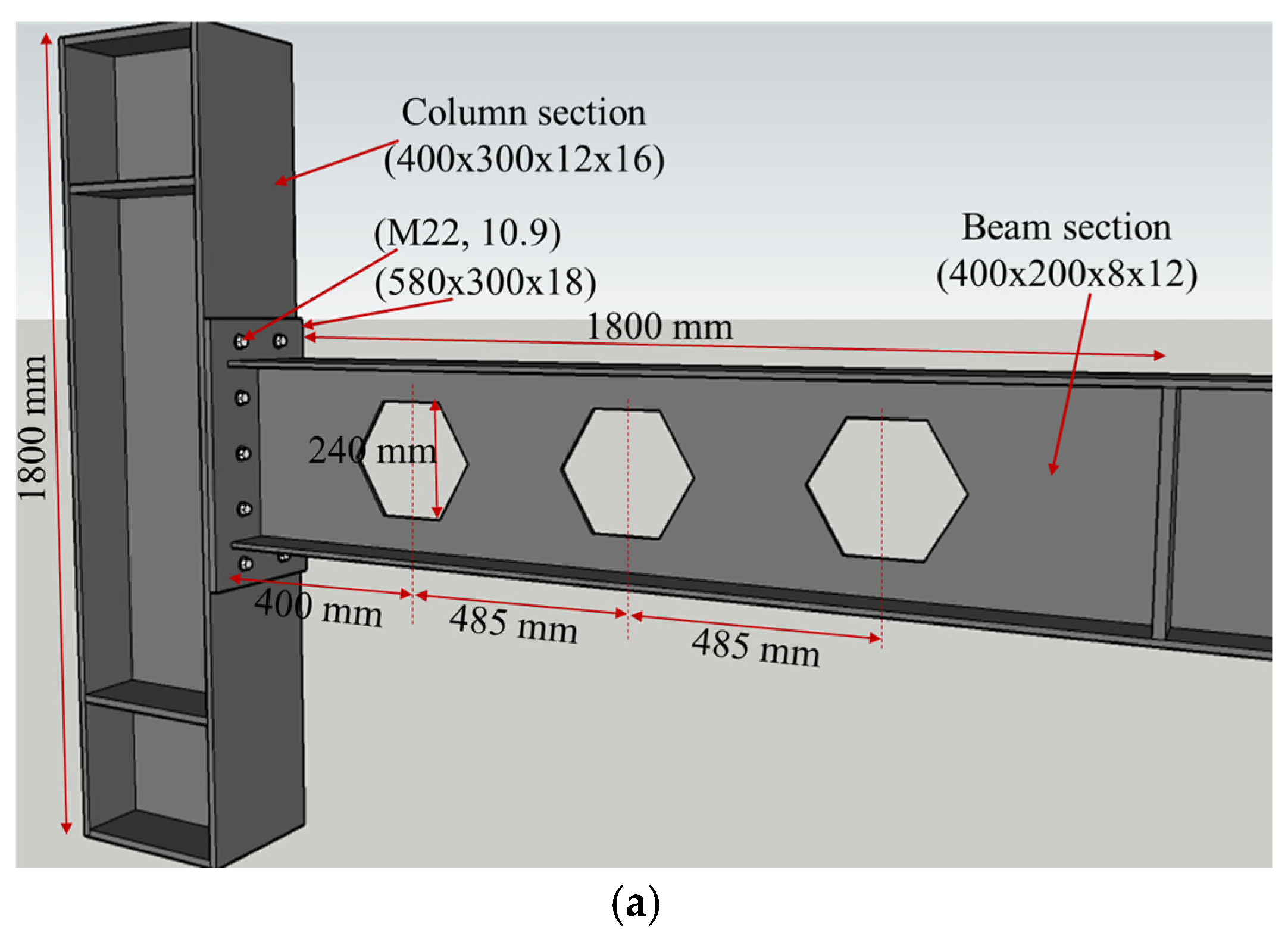
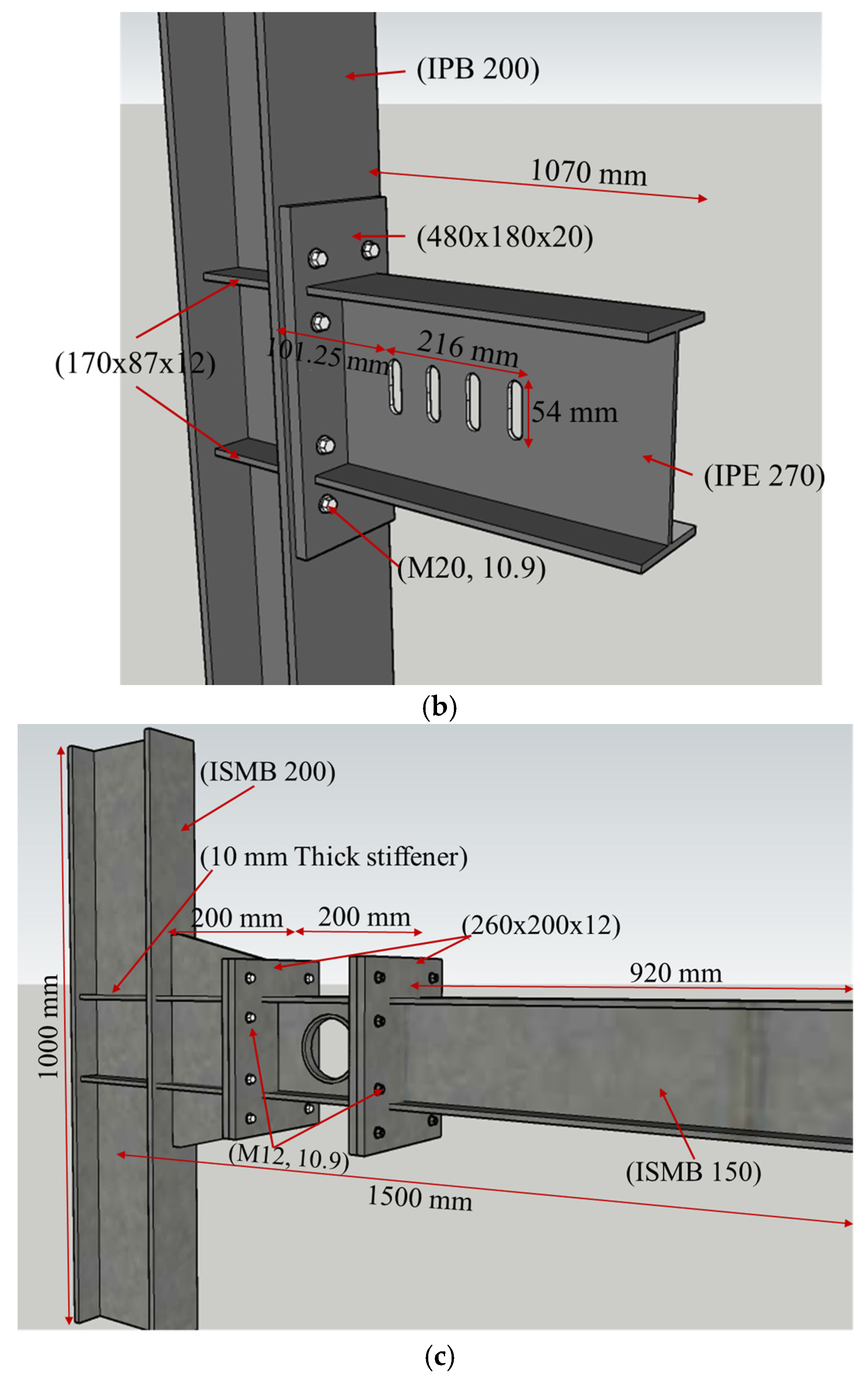
36] was specifically utilized for both validation and parametric analyses. The geometric layout and connection details of three models are illustrated in
Figure 1. Boundary and loading conditions were replicated according to the original experimental setup.
3. FE Model Validation
The FE models were validated through comparison with experimental results that reflect possible failure mechanisms. Initial validations were performed using the RWS configurations, confirming the model’s ability to simulate web buckling, flange buckling, and Vierendeel action. All numerical analyses were conducted using the implicit solver in the ABAQUS/CAE 2019 [
38] software environment.
RWS Connections
To evaluate the performance of RWS connections subjected to monotonic loading, the test specimen HEH60-18, previously studied by [
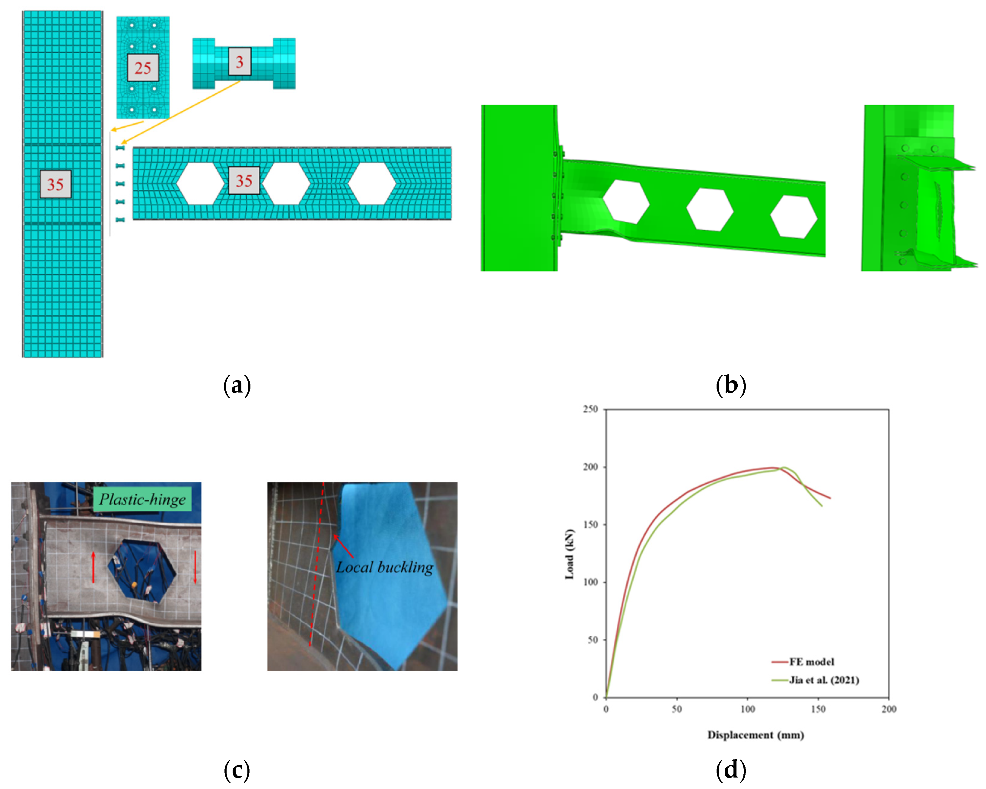
36], was first selected for validation purposes. The specimen’s geometric configuration and the corresponding finite element discretization are illustrated in
Figure 2. All structural components, with the exception of the bolts, were modelled using S4R shell elements; bolts were represented with C3D8R solid elements. The bolt pretension was applied as a bolt load of 190 kN, following the procedure described in their study. A mesh convergence study was carried out, leading to the adoption of element sizes of 35 mm for the beam and column regions, 25 mm for the end plate, and 3 mm for the bolts. In regions anticipated to exhibit elevated stress gradients, mesh refinement was implemented as depicted in
Figure 2a. A surface-to-surface contact interaction was defined to simulate interface behaviour, incorporating a friction coefficient of 0.2 to capture the tangential resistance at potential slip or separation zones. The material behaviour was defined using a multilinear stress–strain curve, derived from experimental data obtained through coupon tests. Boundary conditions consisted of pinned supports at both ends of the column. A displacement-controlled loading protocol was applied by imposing a displacement at a location 1800 mm away from the end plate.
Figure 2 and
Table 2 present a comparison of failure patterns obtained from the FE simulations and experimental tests, indicating that web local buckling developed near the initial opening in both cases. Furthermore, the load–deflection response derived from the FE analysis is matched with the experimental data in
Figure 2d. The FE model effectively reproduced the connection’s load-bearing capacity, with both the simulation and the physical test reaching failure at a load of 200 kN. The model also demonstrated a strong correlation with the experimental results in terms of elastic and plastic behaviour. The numerical analysis identified a distinct failure mode in the reduced web region. Minor discrepancies observed in the structural response are likely due to the idealized material assumptions adopted in the numerical model.
To validate the FE model, the second experimental setup reported by [
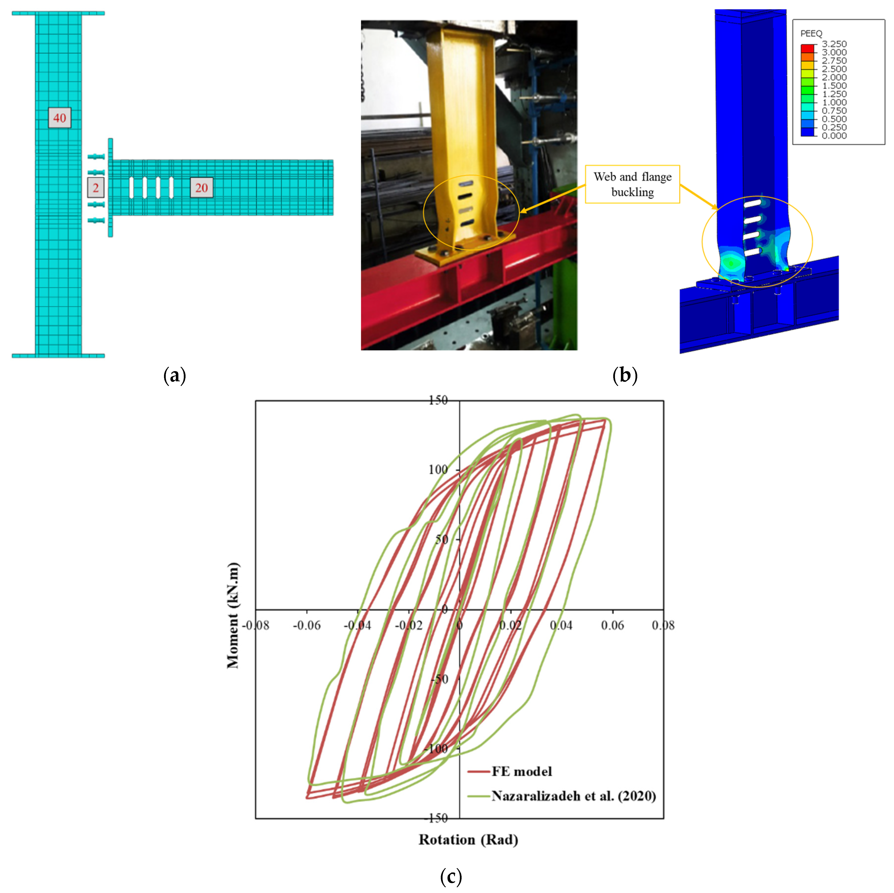
35], which features a vertical-slit reduced web section (VS-RWS), was selected. The model geometry is described in
Figure 1, and the mesh density and boundary conditions were adopted from the original experimental study to ensure consistency (see
Figure 3a). The FE model utilized four-node shell elements (S4R) for the beam and stiffeners, while solid eight-node brick elements (C3D8R) were used to represent the column, end-plate, continuity plates, web plates, and bolts. Steel material behaviour was defined using a tri-linear stress–strain curve, with plasticity governed by the von Mises yield criterion. Combined isotropic and kinematic hardening was applied to accurately capture cyclic response. Contact interactions were modelled using a surface-to-surface approach with a penalty friction formulation (coefficient of 0.2) between the end-plate and column flange. Frictionless general contact was defined between the lateral surfaces of the bolts and the corresponding holes. Loading consisted of two steps: a pretension force of 172.787 kN was first applied to each bolt, followed by quasi-static cyclic loading at a point 1070 mm from the column face. The general static solver was used for the analysis.
Figure 3 presents the developed 3D FE models and meshing details for the VS-RWS connections.
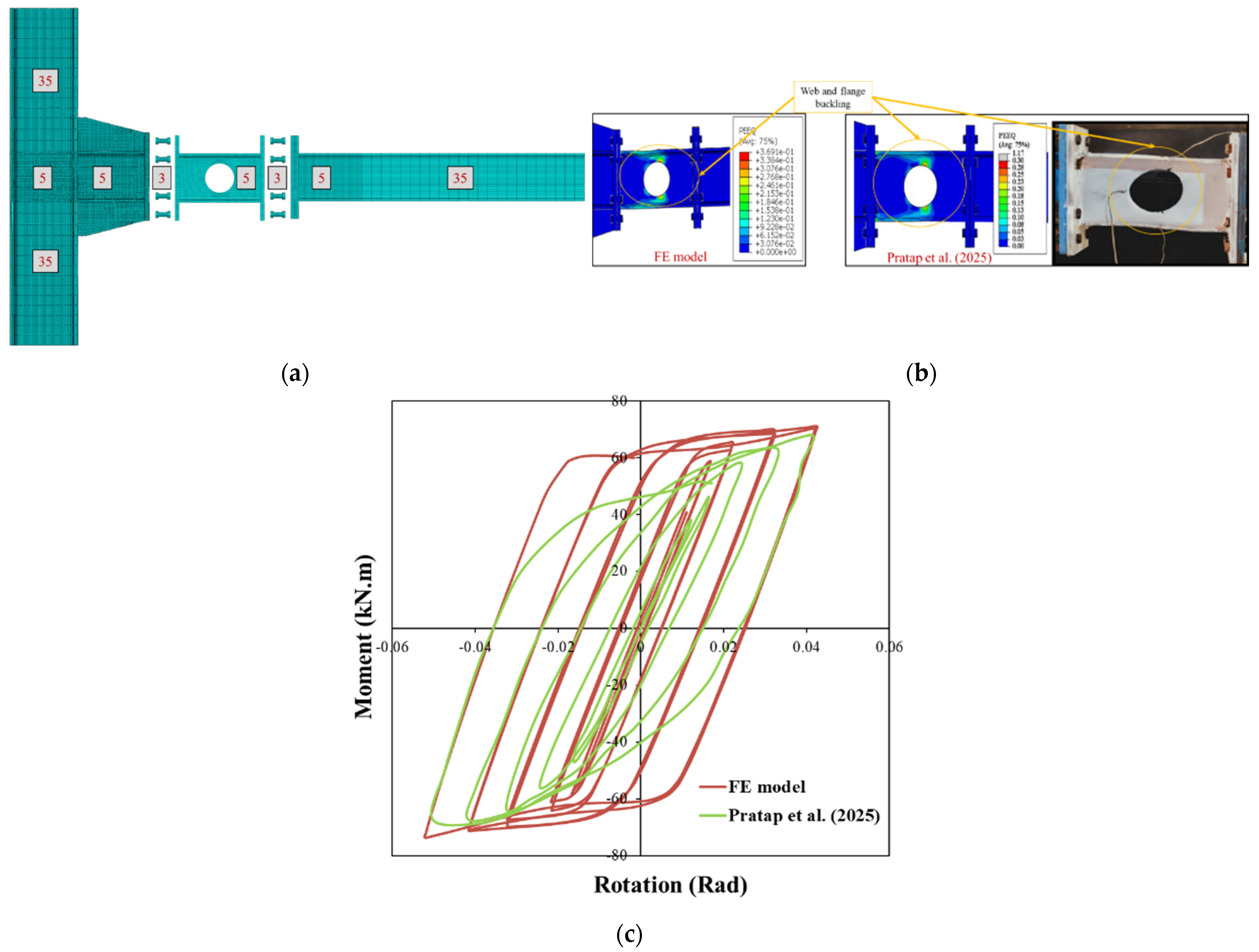
The third validation case, involving a fuse-type connection [
37], was analyzed using ABAQUS. Both material and geometric nonlinearities were included through true stress–strain input and combined hardening for cyclic behaviour. All parts, beam, column, fuse, bolts, and end-plate were modelled with C3D8R elements. During the initial analysis, a bolt pretension equal to 0.7 times the bolt’s ultimate stress was applied at the pretension nodes along the shank using ABAQUS. After establishing pretension, the analysis continued with a displacement-controlled static step using the Newton–Raphson procedure. A mesh sensitivity study under monotonic loading determined an efficient mesh: 5 mm elements in critical regions, up to 35 mm elsewhere as depicted in
Figure 4. Boundary conditions matched the experiment, with both column ends fixed. Welded joints were represented using tie constraints. Bolt contact used surface-to-surface interaction with penalty friction (μ = 0.2) and finite sliding. The simulation included two steps: bolt pretensioning, followed by displacement-controlled cyclic loading per AISC 341–2016. A general static solver with Newton–Raphson iterations was used to obtain force–displacement results.
Plastic hinges primarily form at the mid-height of the web-to-flange connections near the openings in circular fuses. Local buckling is also concentrated in this area, and final failure remains confined to the fuse component.
Figure 4b shows that the equivalent plastic strain (PEEQ) reaches a maximum value around 0.30 in this region. During early loading cycles with low magnitudes, the fuse behaves elastically and maintains flexural performance up to 0.02 radians of rotation. As loading progresses, the fuse begins to yield and dissipate energy through plastic deformation, continuing up to 0.04 radians as illustrated in
Figure 4. A good level of accuracy is observed between the numerical and experimental failure patterns, confirming the accuracy of the FE model (see
Figure 4c).
4. Proposed Sleeve System
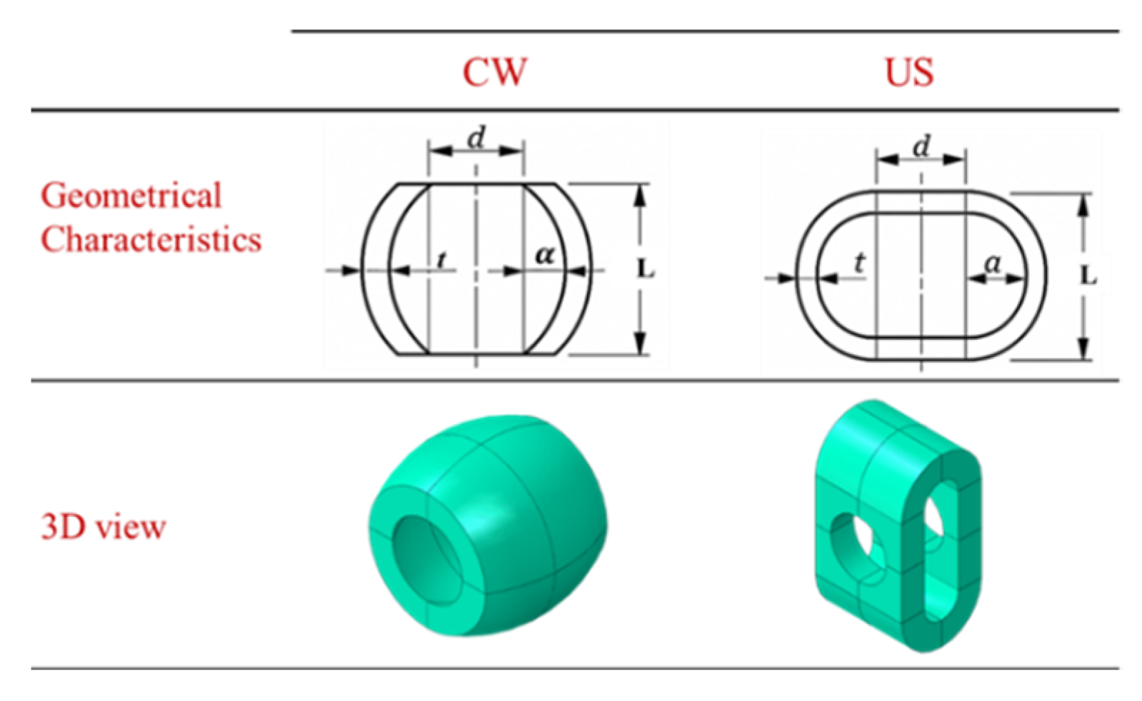
This proposed sleeve fuse system is designed to enhance the deformation capacity of steel structure connections. For this purpose, two specific geometric configurations are introduced to improve the rotational performance of end-plate connections. The sleeve, positioned between the end plate and the washer, is defined by its length (L), thickness (t), and wall amplitude (a), where the amplitude represents the peak deviation of the sleeve wall from its mean radius and has the dimension of length. Two forms are explored: the circular wave (CW) and the U-shaped wave (US) (see
Figure 5). To achieve greater ductility, the sleeve is engineered to deform prior to the failure of any other connection component, meaning its ultimate load capacity must remain below the tensile strength of the bolt. The deformation behaviour of the sleeve is directly influenced by its amplitude: (1) low amplitudes result in limited deformation, often causing premature bolt failure; (2) moderate amplitudes allow partial plastic deformation before bolt rupture; and (3) plastic amplitude (PA) enables extensive sleeve deformation, absorbing energy before the bolt fails. Acting as a replaceable energy-dissipating device, the sleeve localizes inelastic behaviour within itself, protecting the rest of the connection and enhancing seismic resilience. Although the sleeve deforms under relatively small forces, its geometry is optimized to balance ductility and initial stiffness. After significant loading events, sleeves should be inspected and, if necessary, replaced or retrofitted to maintain connection performance. The sleeve fuse configurations utilized in this study are summarized in
Table 3. Each configuration is identified using a standardized code, such as CWx34-3-5, which reflects the primary geometric characteristics of the sleeve. In this notation, CW indicates a circular waveform profile, 34 represents the sleeve length, 3 corresponds to the amplitude of the waveform, and 5 denotes the sleeve thickness, with all dimensions given in mm. This systematic labelling approach ensures accurate and consistent reference to the geometry of each sleeve fuse examined. It should be noted that the sleeve lengths (L) for both types of sleeves were selected within the range of 1.25 d to 2 d, where d denotes the bolt diameter.
5. Validation of Sleeve Fuse Behaviour: Component and Connection-Level Insights
This section presents a comprehensive experimental and numerical investigation of the proposed sleeve fuse, assessed at both the component and connection levels. Three test configurations were examined: (1) a single sleeve specimen subjected to axial compression, (2) a bolted sleeve assembly tested under tensile force, and (3) a full T-stub connection incorporating the sleeve, subjected to monotonic tension. These tests were conducted to validate the mechanical behaviour and deformation capacity of the sleeve system and its performance when integrated into structural connections. The material properties are given in
Table 4.
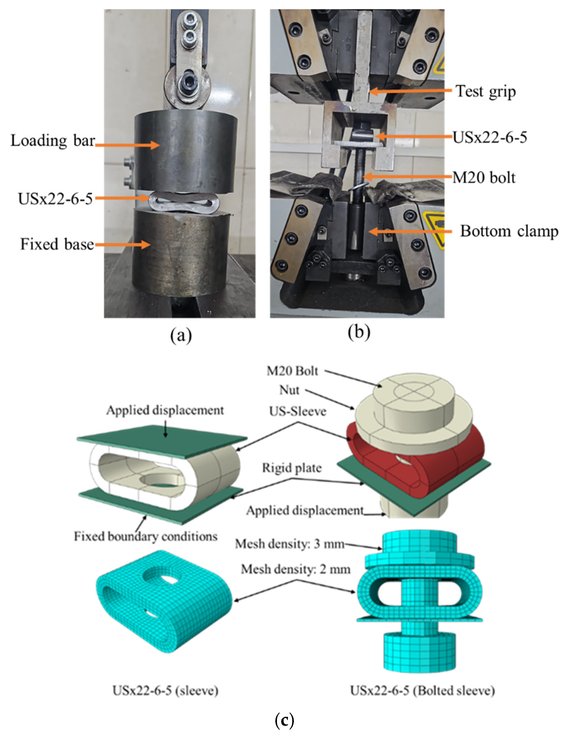
The standalone test was conducted on a USx22-6-5 sleeve, featuring a 22 mm length, 6.0 mm wave amplitude, and 5.0 mm wall thickness. In the first setup, the sleeve was placed between a fixed base and a loading head and compressed axially (
Figure 6a). In the second configuration, the sleeve was paired with an M20 Gr 8.8 bolt and 3 mm washer and tested in tension to simulate its role in resisting compression within a bolted connection (
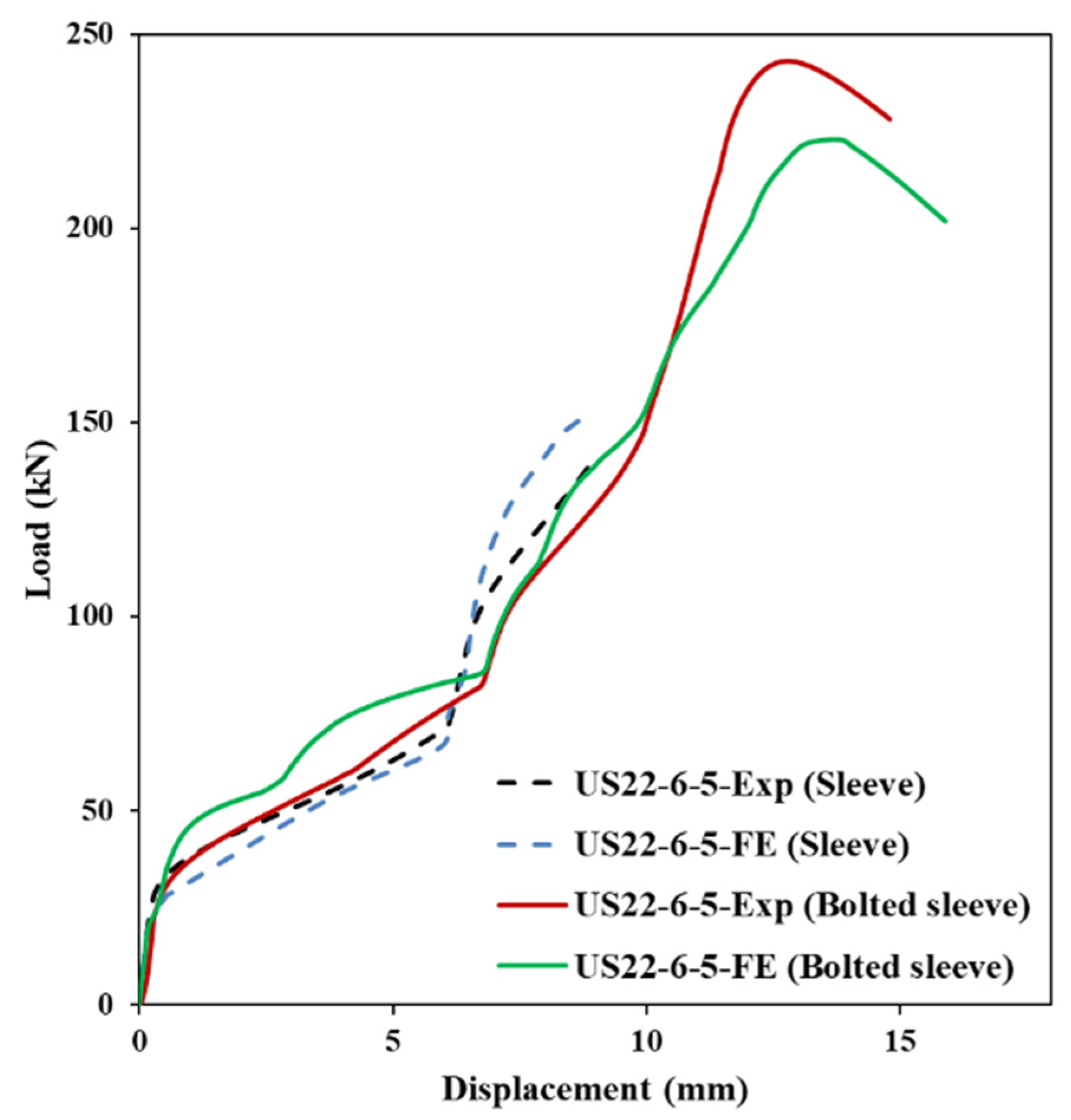
Figure 6b). Both tests were performed on a 600 kN Instron testing machine under displacement control (3.0 mm/min). The experimental load–displacement curves demonstrated a clear elastic–plastic transition and progressive deformation leading to failure. The unbolted sleeve exhibited three distinct response stages: linear elastic behaviour, nonlinear plastic deformation, and gradual softening due to local crushing. The bolted sleeve showed similar initial stiffness and deformation trends, with the bolt governing the tensile response.
Corresponding FE models were developed in ABAQUS using C3D8R brick elements. Material behaviour was defined using isotropic hardening plasticity based on tensile coupon tests. A friction coefficient of 0.4 was used between the sleeve and endplate, as well as between the sleeve and washer, consistent with previous studies [
28], which demonstrated that the FE models accurately capture the sleeve behaviour for μ ≥ 0.2 [
39]. Boundary conditions and loading were modelled to replicate the test setups, including the axial constraint of the rigid plate and displacement-controlled loading applied through the bolt nut. The FE simulations showed excellent agreement with the experimental results in terms of both global response and local failure mechanisms. As shown in
Figure 7, the models accurately captured the stiffness, yield behaviour, and post-peak response of both sleeve configurations.
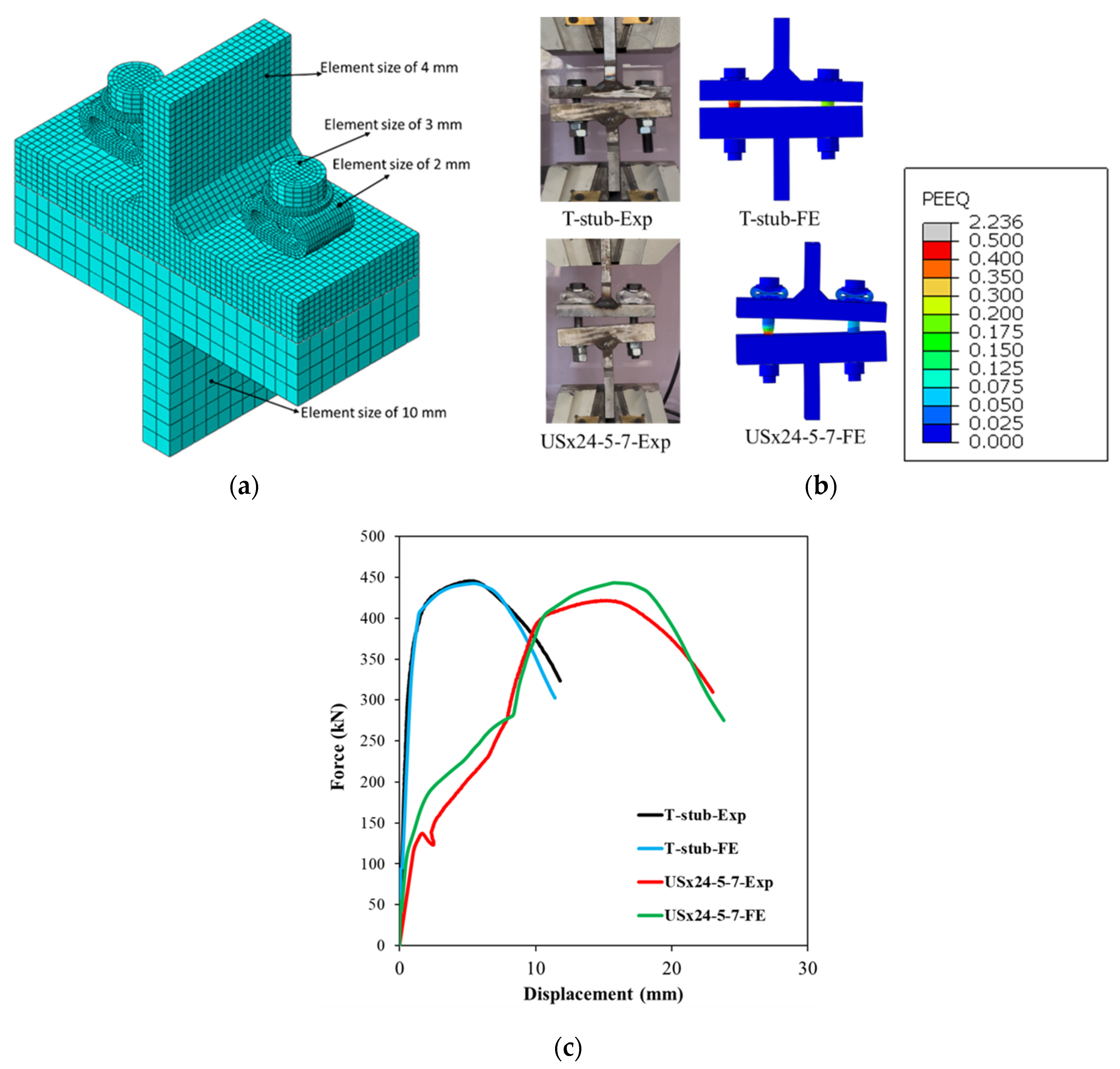
To evaluate the sleeve’s effect at the connection level, two T-stub assemblies were tested under monotonic tensile loading: a standard T-stub and a sleeved T-stub incorporating the USx24-5-7 sleeve model. The specimens had flange and web thicknesses of 27 mm and 20 mm, respectively, and were connected to a rigid T-stub with a 40 mm flange and 20 mm web, designed to remain elastic during loading. All components were fabricated from S355 steel and joined with 15 mm fillet welds sized to exceed the bolt strength, ensuring bolt-dominated failure. Each connection used two M20 Gr 8.8 bolts, as illustrated in
Figure 8. The tested assemblies are shown in
Figure 8a.
The force–displacement behaviour of the T-stubs is presented in
Figure 8c. Numerical models developed for both configurations closely matched the experimental results, capturing not only global stiffness and strength but also localized deformations and failure progression (
Figure 8b). The sleeved T-stub demonstrated significantly enhanced ductility—nearly twice that of the standard T-stub—while maintaining a similar load-bearing capacity. This improvement highlights the sleeve’s potential to increase energy dissipation and delay fracture under tensile loading.
Overall, the experimental and numerical investigations confirmed the effectiveness of the proposed sleeve device. The FE models proved reliable in predicting both load response and failure modes across all configurations—standalone sleeve, bolted sleeve, and full T-stub assembly—establishing a solid foundation for further parametric studies and design applications. It should be noted that the T-stub tests and corresponding numerical models were conducted on bearing-type connections without bolt pretension. For pre-tensioned connections, the sleeve capacity must exceed the applied pretension to avoid premature crushing; behaviour under pretension is beyond the scope of this study.
6. Parametric Study
The validated experimental model developed by Jia (2021) [
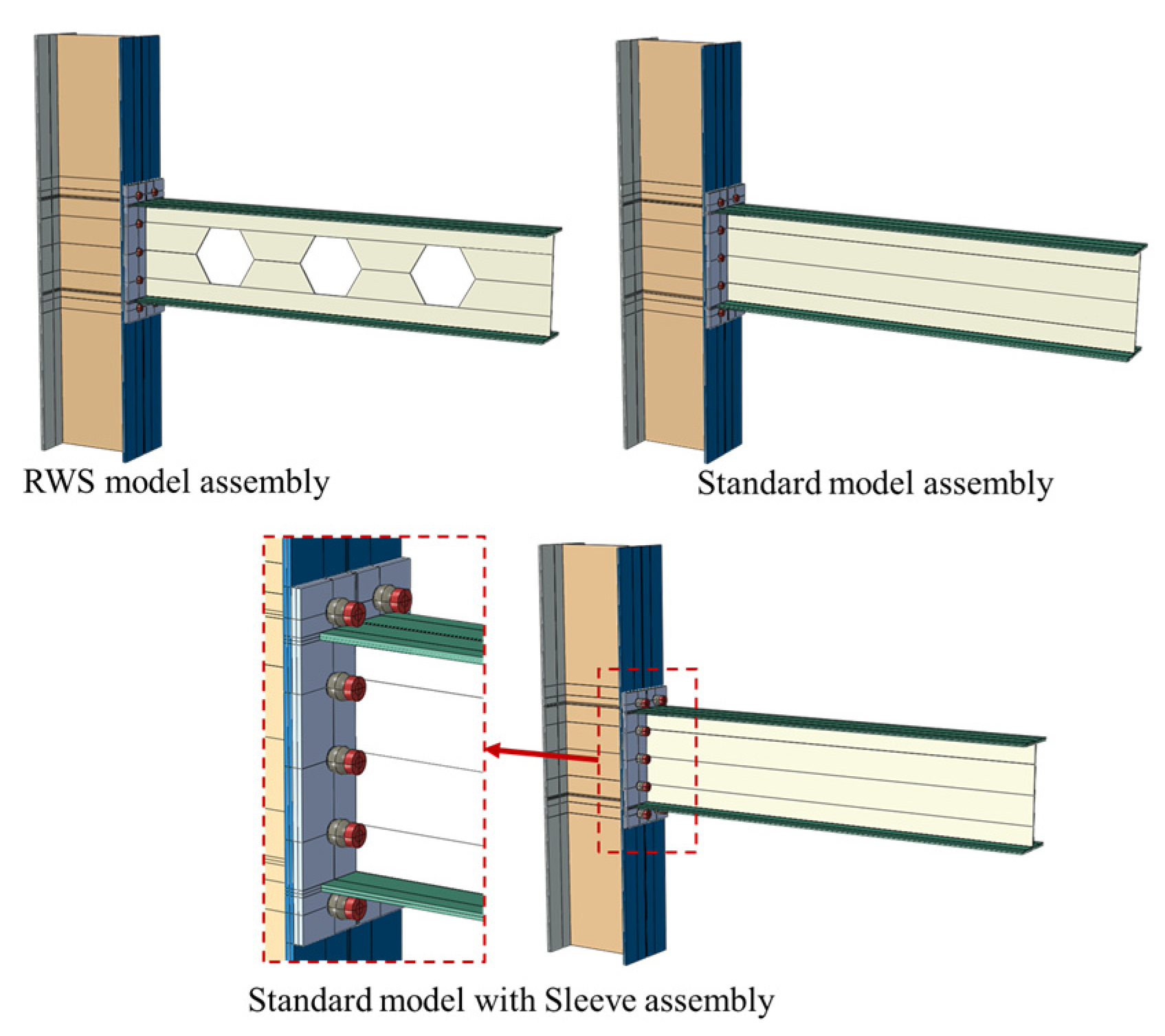
36] was adopted for the parametric study. To focus on the replicable sleeve fuse system’s performance, reduced hexagonal web sections were removed from the beam web (see
Figure 9). Boundary and loading conditions matched the experimental setup for consistent comparison. This modified setup, called the standard connection, evaluates the proposed fuse system against the RWS connection.
Since failure mode is critical for performance evaluation, the comparison is based on dominant failure mechanisms. Bolt failure governs the response for both the standard connection and the sleeve fuse system, while RWS fails mainly due to local buckling. This allows clear assessment of how the fuse system affects and delays bolt failure with increasing deformation. All analyses ended once load dropped to about 80% of peak.
6.1. Behaviour of the Replicable Sleeve Fuse System Under Monotonic Loading
This section investigates the structural performance of the replaceable sleeve fuse connection under monotonic loading, focusing on its ability to prevent premature bolt failure by redistributing forces and promoting controlled plastic deformation in the sleeve. Two reference models are considered: the standard connection without energy-dissipating components, and the RWS connection with beam web modifications to shift plastic hinging away from bolts. In the proposed design, the sleeve sits between the nut and endplate, yielding and absorbing energy before bolt damage. The analysis examines displacement capacity, equivalent plastic strain (PEEQ) distribution, and dominant failure mechanisms to understand how the sleeve delays bolt failure and improves energy dissipation compared to the standard and RWS connections.
CW and US sleeve designs were used as sacrificial fuses to enhance rotational capacity. A parametric study varied sleeve length, amplitude, and thickness to assess effects on displacement capacity. Twenty-five sleeve configurations were developed: 12 CW and 13 US variations. Sleeve length was kept between 1.25 and 2 times the bolt shank diameter (d). For CW fuses, thickness was constant at about 0.25 d.
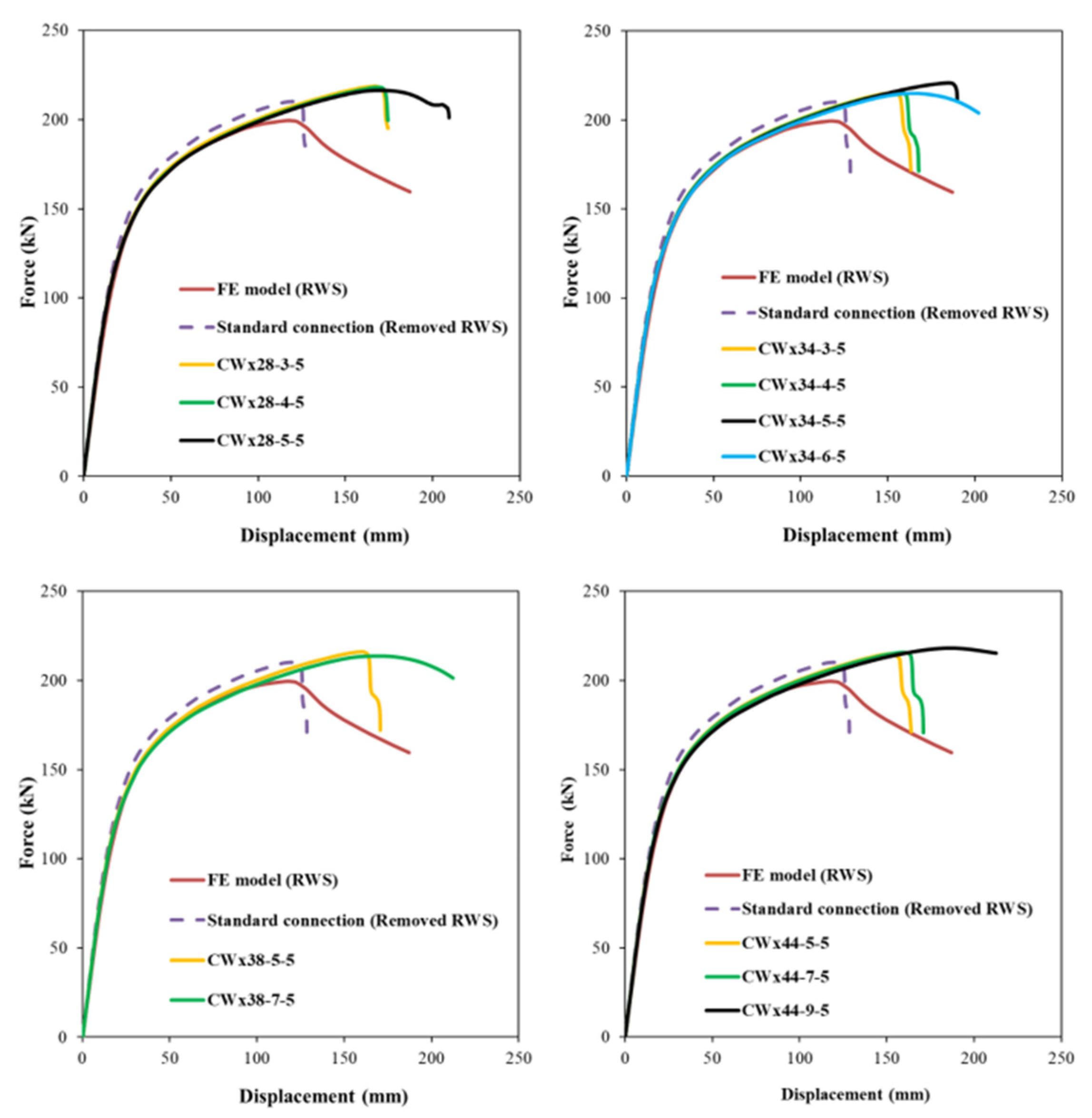
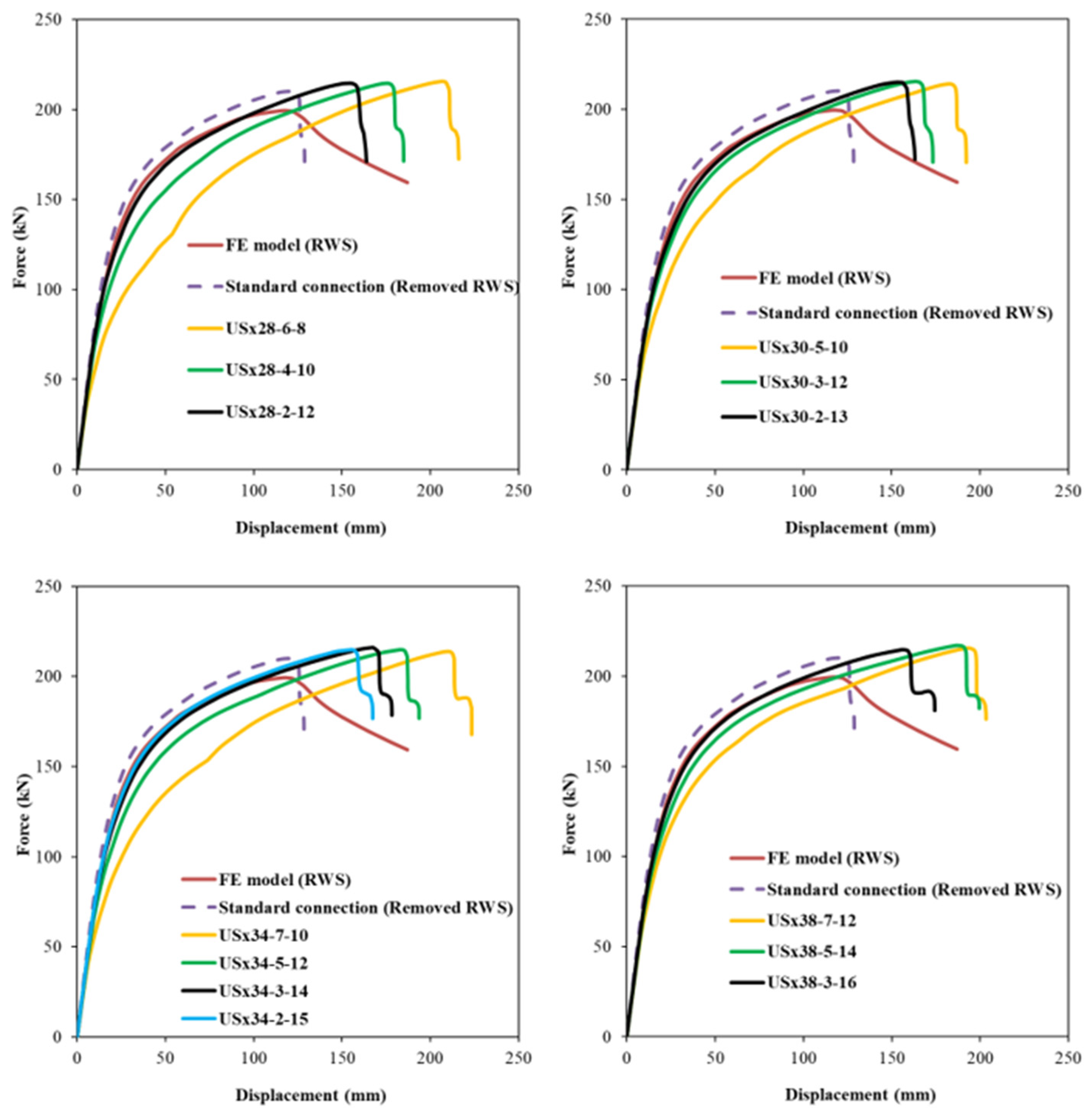
Figure 10 and
Figure 11 illustrates the structural response of beam–column end-plate bolted connections with the standard configuration, RWS system, and proposed sleeve fuse mechanism. CW-type sleeve configurations accurately capture elastic behaviour. Initial stiffness ratios (
Table 5) show fused connections have stiffness comparable to RWS and standard setups, ranging from 1.0 to 1.1. Regarding ultimate load capacity, CW sleeves perform similarly to RWS and standard connections (
Table 5). All CW sleeves exhibit greater displacement capacity than the standard connection. However, specific configurations (CWx28-3-5, CWx28-4-5, CWx34-3-5, CWx34-4-5, CWx38-5-5, CWx44-5-5, CWx44-7-5) show reduced ductility versus RWS, due to the sleeves’ higher strength relative to bolt capacity, causing bolt shank failure (see
Figure 10).
Conversely, models such as CWx28-5-5, CWx34-5-5, CWx34-6-5, CWx38-7-5, and CWx44-9-5 exhibit superior deformation capacity compared to RWS with equivalent load capacity. In these, complete sleeve failure is followed by bolt shank failure.
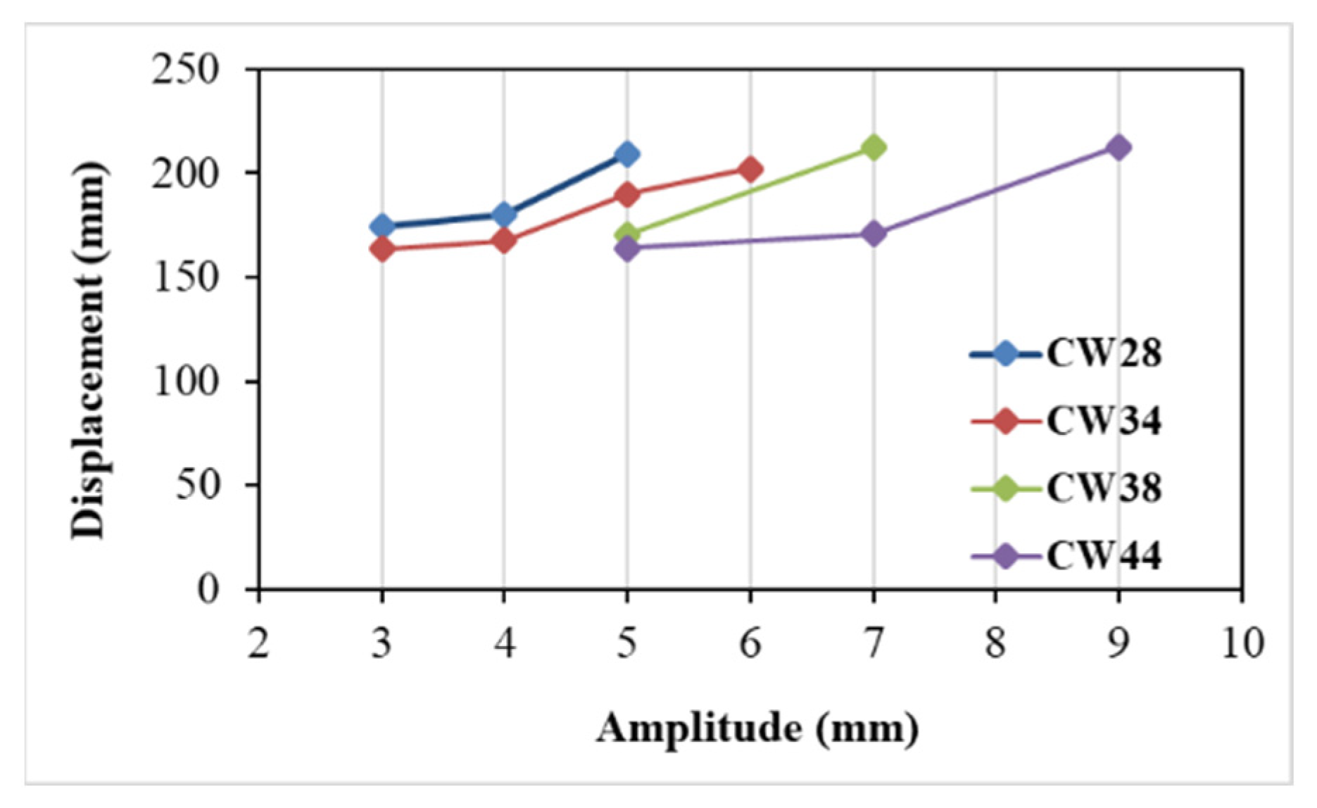
Figure 12 also shows displacement capacity increases with sleeve amplitude. US sleeve fuse responses differ. Larger amplitude US sleeves tend to be more flexible, while lower amplitude, thicker sleeves behave rigidly, similar to RWS and standard connections. The USx38-3-16 sleeve exceeded bolt load capacity, preventing full sleeve failure; others failed fully before bolt failure. Stiffer US sleeves follow elastic trends of RWS and standard models, while weaker sleeves like USx28-6-8 and USx34-7-10 reduce initial stiffness by ~25% and 10%, respectively (
Table 5). The USx34-7-10 reached the highest displacement capacity of 223 mm. Peak loads of US sleeves matched RWS and standard connections.
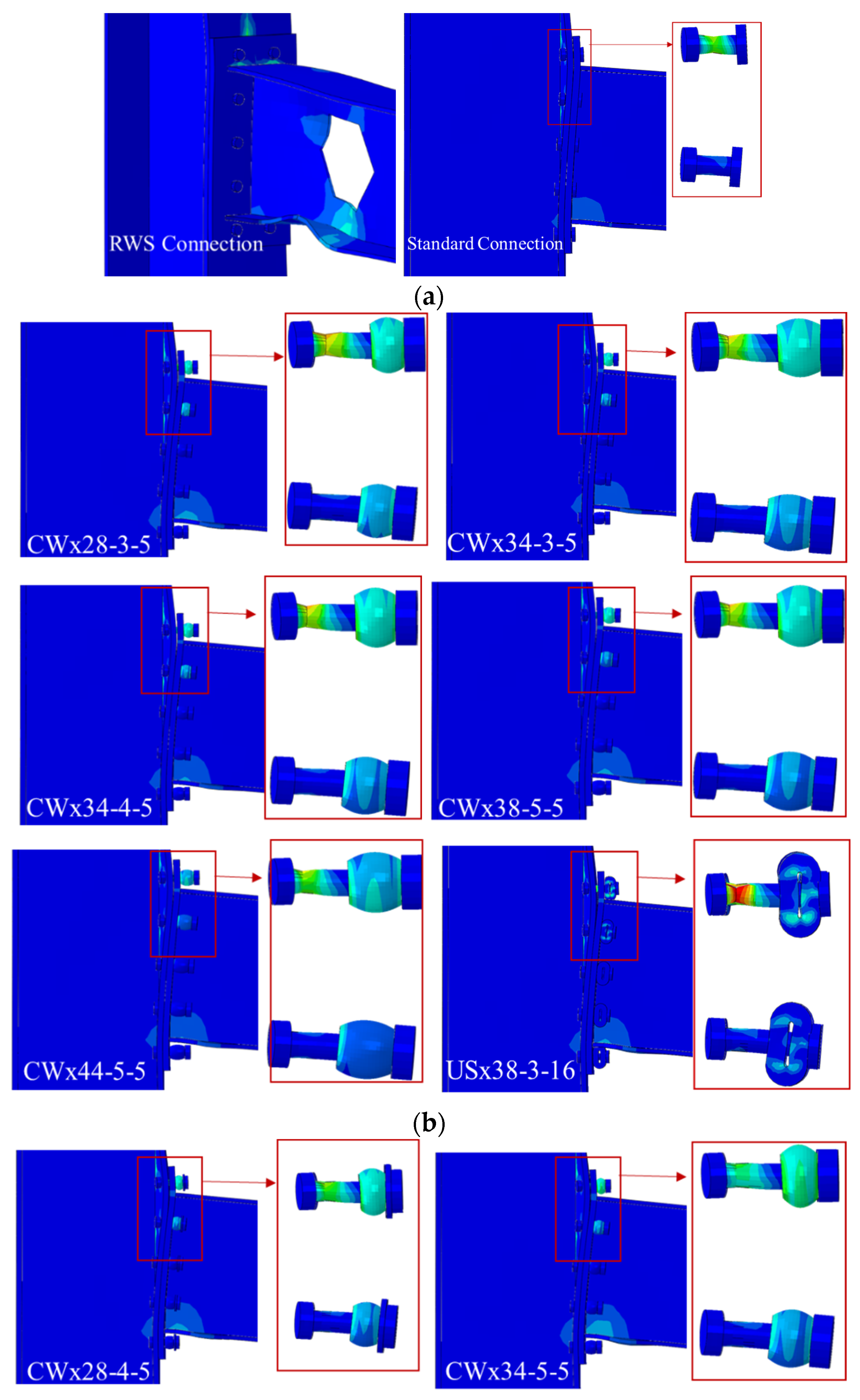
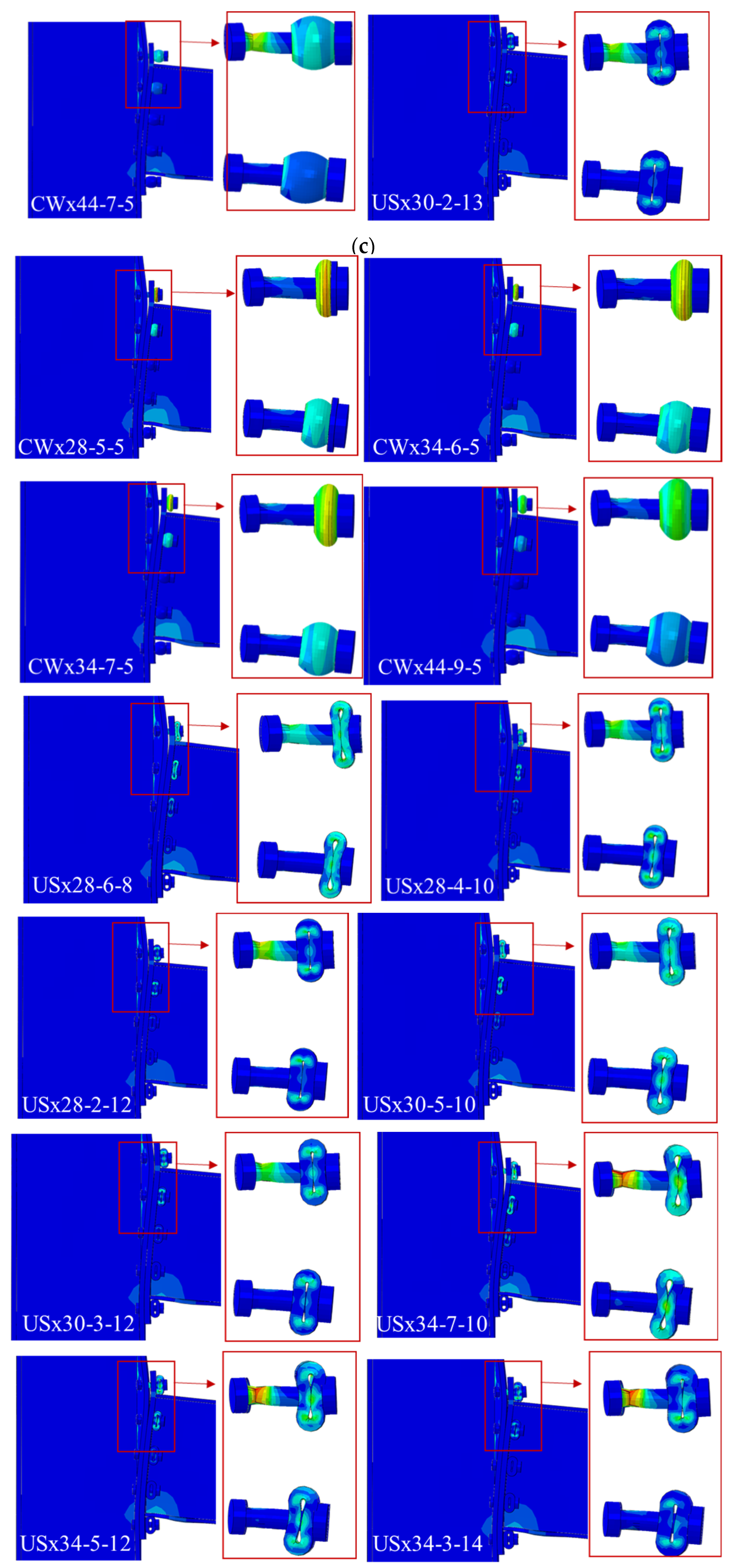
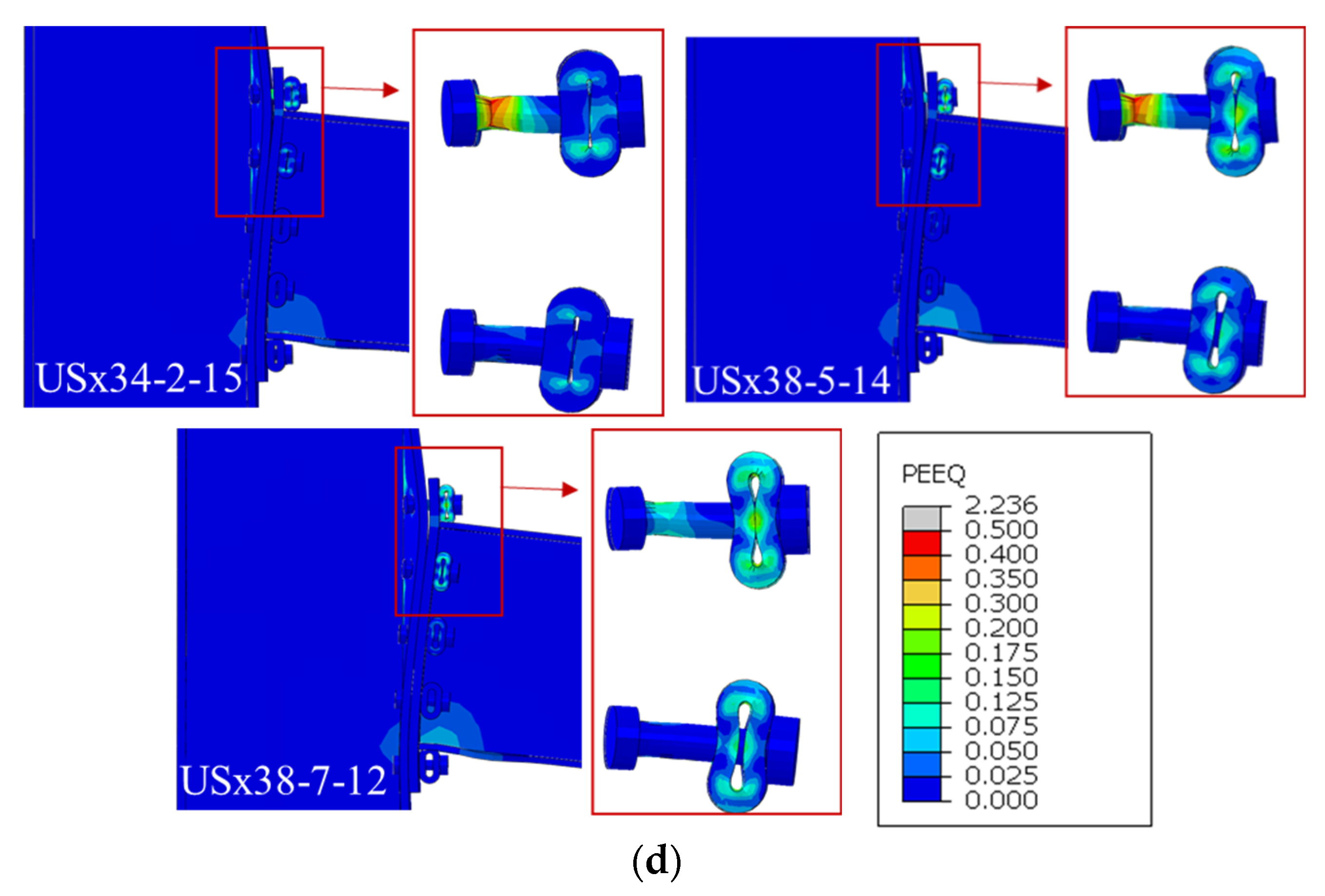
Figure 13 shows deformation and failure modes at 20% load drop from peak. RWS and standard connections exhibit conventional plastic deformation (
Figure 13a). Sleeved connections show varied failure modes: bolt failure without sleeve deformation (
Figure 13b), partial sleeve deformation with bolt failure (
Figure 13c), and complete sleeve failure indicating full activation and energy dissipation (
Figure 13d).
6.2. Ductility and Energy Dissipation
Recent studies on various structural systems emphasize that achieving greater deformation capability and establishing stable energy-dissipation mechanisms are key factors in improving the resilience of structures subjected to severe loading conditions [
32,
33,
34].
Table 6 summarizes ductility values, normalized ductility ratios (
μSleeve/
μRWS), total energy dissipation capacities, and percentage changes relative to the RWS baseline for all connection configurations. The ductility factor (
μ) is defined as the ratio of displacement at 80% of the peak load to the yield displacement (
μ = Δ
0.8Pmax/Δ
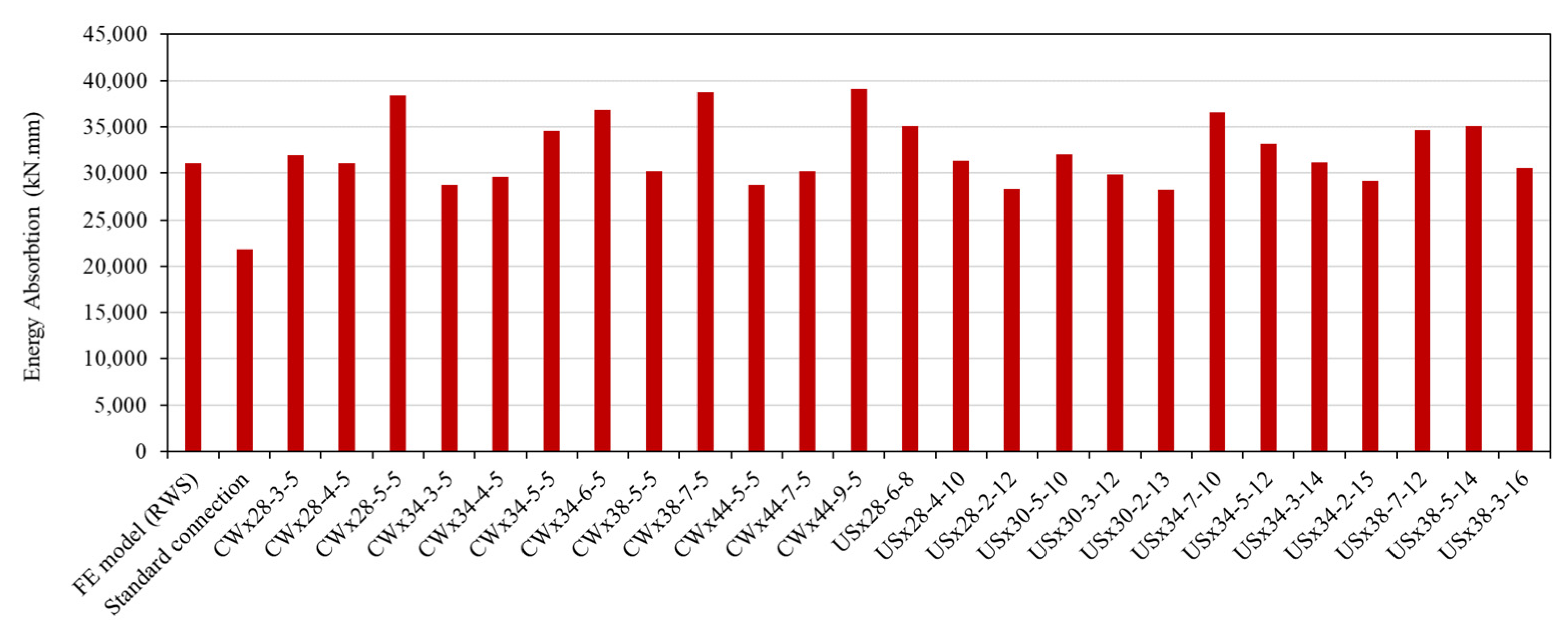
y), reflecting the connection’s post-yield deformation capacity. Total energy dissipation, calculated as the area under the load–displacement curve, indicates the connection’s ability to absorb and dissipate seismic energy. Several sleeve fuse configurations surpassed the RWS connection in ductility and energy absorption. While RWS served as a benchmark, certain CW and US sleeve models with optimized amplitude and thickness demonstrated superior deformation capacity and energy dissipation, indicating that properly designed sleeve fuses can enhance inelastic performance beyond conventional RWS.
The standard connection, excluding the RWS region, showed a −29.70% reduction in energy dissipation. Several CW sleeves (e.g., CWx28-5-5, CWx34-5-5, CWx38-7-5, CWx44-9-5) outperformed RWS in both ductility and energy dissipation, with CWx44-9-5 showing the largest increase (25.88%). Some CW models with smaller amplitudes or thicknesses showed slightly reduced performance (
Table 6). US sleeves generally exhibited superior ductility, with USx34-7-10 and USx30-5-10 reaching 16.81 and 14.13, respectively. USx34-7-10 also achieved one of the highest energy absorption levels. Even models with moderate ductility improvements (e.g., USx28-4-10, USx38-5-14) surpassed RWS in energy dissipation (
Table 6).
Figure 14 visually compares energy absorption for all models. Several sleeve configurations—CWx28-5-5, CWx34-6-5, CWx38-7-5, CWx44-9-5, and USx34-7-10—exhibit superior energy dissipation compared to standard and RWS connections, confirming the sleeve fuse concept’s effectiveness.
7. Discussion and Limitations
The results of this study highlight the potential of the proposed sleeve fuse to modify and control the deformation pattern in end-plate connections. The sleeve effectively localizes plastic deformation away from the beam flanges and column face, reducing the likelihood of crack initiation in the welds or beam web—a known concern in RWS-type connections. This behaviour provides an engineering advantage in situations where damage concentration within a replaceable component is preferred over inelastic deformation in primary structural members.
From a practical standpoint, the sleeve introduces a simple and low-cost replaceable device that can be integrated into standard extended end-plate details without altering the global connection geometry. This makes the system attractive for both retrofitting existing structures and designing new frames with enhanced reparability. The parametric results further show that the sleeve stiffness and post-yield behaviour can be tuned by adjusting geometric parameters, allowing designers to achieve targeted performance levels.
Despite these advantages, several considerations limit the immediate application of the findings. The present numerical investigation assumes idealized material properties and controlled geometric tolerances for the sleeve. In real applications, variability in steel strength or manufacturing tolerances may influence the connection fusibility and should be addressed through appropriate quality control measures or safety factors.
The analyses in this study were conducted under monotonic loading to isolate the fundamental response characteristics of the sleeve fuse. However, moment-resisting frames are subjected to cyclic and reversing loads during earthquakes. Under such conditions, the sleeve’s deformation history, potential stiffness degradation, and cumulative damage effects may influence the global hysteretic response of the connection. These aspects require further cyclic numerical and experimental studies to confirm the robustness of the proposed system under realistic seismic demands.
Another limitation is that the analyses focused on a single beam–column subassembly. In an actual frame, the behaviour of adjacent connections may affect the global deformation pattern and the demand imposed on the sleeve. Interactions between multiple fuses—especially under large drifts or catenary action—may alter the distribution of forces within the frame. A system-level assessment is needed to evaluate whether sleeve crushing, redistribution of forces, or second-order effects could influence collapse mechanisms.
The T-stub results show that overly flexible sleeves can deform noticeably at low force levels, reducing the initial stiffness of the connection. In an actual end-plate joint, this may lead to additional beam-end deflection under service loads. Therefore, sleeve configurations with low stiffness should be avoided in cases where serviceability control is critical, and the sleeve geometry must be selected to balance deformability and stiffness.
Finally, the study focuses on the comparison between the sleeve fuse and the RWS configuration. While the results indicate improved rotational capacity and controlled damage in the sleeved connection, further calibration is needed to establish design equations, capacity predictions, and detailing requirements to integrate the sleeve into existing design standards.
8. Conclusions
This study investigated the performance of an innovative sacrificial sleeve fuse in bolted endplate connections through experimental tests and validated numerical simulations. The sleeve, a curved-wall steel tube placed between the endplate and washer, redirects inelastic deformation, promoting ductile failure while preserving the primary structural components.
Comparisons with standard and RWS connections demonstrated significant enhancements in both ductility and energy dissipation. Circular waveform (CW) sleeves exhibited linear elastic behaviour with sleeve crushing preceding bolt failure, improving rotational capacity. U-shaped (US) sleeves showed slightly lower initial stiffness but substantially increased deformation capacity. Experimental T-stub tests confirmed these findings, with the USx24-5-7 sleeve nearly doubling displacement at failure compared to standard T-stubs. Optimized sleeve configurations, such as USx34-7-10 and CWx44-9-5, achieved ductility ratios of μ = 16.81 and energy dissipation increases of 17.55% and 25.88% relative to RWS connections.
The proposed sleeve fuse system serves as a replaceable energy-dissipating component, concentrating inelastic deformation within the sleeve while preserving the primary structural elements. Design guidance on sleeve geometry, thickness, and placement allows engineers to tailor the device for different connection sizes and loading demands. Its modular and non-welded configuration makes it suitable for retrofitting existing frames as well as new construction, facilitating post-event repair and enhancing seismic resilience. Overall, the sacrificial sleeve fuse provides a practical, replaceable solution that improves seismic performance, making it a promising approach for both new constructions and retrofits.
