Article

Monitoring Method for the Self-Bearing Process During the Construction of Long-Span Steel Roof Structures with Ring Beams

1
School of Intelligent Civil and Ocean Engineering, Harbin Institute of Technology (Shenzhen), Shenzhen 518055, China
2
China Construction Steel Structure Co., Ltd., Beijing 100029, China
*
Author to whom correspondence should be addressed.
Buildings 2025, 15(23), 4293; https://doi.org/10.3390/buildings15234293
Submission received: 13 October 2025 / Revised: 21 November 2025 / Accepted: 25 November 2025 / Published: 27 November 2025

Abstract

Long-span steel roofs with spatial ring beams as their primary load-bearing elements are widely adopted in large stadiums and public facilities. Their construction involves complex stages—ring beam assembly, closure and staged falsework unloading—during which boundary conditions, internal forces and overall stiffness change considerably. This study proposes a stiffness monitoring method that evaluates the self-bearing process of such structures based on measured stress and displacement data. The method establishes a stiffness matrix for different construction stages and introduces an indicator of stiffness change rate to quantify stiffness evolution during unloading. To validate this approach, finite element method simulations were conducted, and their predictions were compared with monitoring data from the Shenzhen Stadium steel roof. The monitored and simulated stiffness variation trends show strong agreement, thereby validating the applicability of the proposed monitoring framework. The method enables real-time tracking of structural safety, supports optimisation of the unloading sequence and enhances our understanding of stiffness evolution during construction. Overall, this study presents a validated, data-driven framework for monitoring and optimising the self-bearing process of long-span steel roof structures, thereby improving both construction safety and service performance.

1. Introduction

Large-span steel roof structures have become increasingly prevalent in modern architectural and civil engineering projects, particularly in large public venues such as stadiums, exhibition halls and transportation hubs. These structures display complex mechanical behaviour as they evolve from formwork-supported systems to self-supporting configurations during construction. This transformation entails intricate load redistribution, stiffness development and time-dependent stress variation, all of which exert a substantial influence on construction safety and long-term performance.
Numerous researchers have conducted detailed investigations into the mechanical behaviour, construction performance and safety assessment of long-span and membrane roof systems. For instance, Ngamkhanong and Kaewunruen examined the vibration behaviour, structural resilience and load redistribution mechanisms of long-span steel and composite systems, emphasising the effects of construction sequence, boundary conditions and environmental factors on global stiffness and dynamic response [1,2]. Chucheepsakul and Sibanda further conducted foundational analytical studies on cable-supported and membrane structures, developing nonlinear formulations to characterise large-deformation behaviour and dynamic response under complex loading scenarios [3,4]. Kaewunruen, Ngamkhanong and Baniotopoulos investigated the aerodynamic stability and wind–structure interaction of long-span roofs, clarifying the roles of geometric nonlinearity and material anisotropy in shaping global stiffness development and service-state stability [5,6]. Collectively, these studies demonstrate that long-span roof systems are highly sensitive to both construction sequence and boundary evolution, necessitating continuous monitoring and analytical control throughout staged construction.
In addition, previous research has revealed that discrepancies between one-time loading schemes in finite element simulations and analyses that incorporate construction path effects can lead to considerable deviations between predicted and actual stress states [7,8]. The nonlinear coupling of stiffness evolution with geometry and boundary condition changes in complex spatial structures [9] as well as the time-dependent nature of internal force development during construction [10,11] can substantially alter the final equilibrium configuration. In response, several studies have proposed improved methods for structural monitoring and performance evaluation. Huang et al. analysed stress data from the ring beams of the Huanglong Sports Centre Main Stadium, showing that temperature effects could induce beam deflections exceeding design values [12]. Wu et al. conducted unloading analyses of Laiyang Stadium, demonstrating that the removal of formwork led to considerable increases in ring axial forces while maintaining acceptable displacement levels [13]. Prem further developed a multiparameter evaluation framework incorporating stiffness indices, stress ratios and displacement limits to assess construction-stage safety for long-span steel structures [14].
Despite these advances, the mechanisms underlying stiffness formation and the development of self-bearing capacity in ring-beam-based long-span roofs remain inadequately understood. The transition from a temporarily supported configuration to a self-bearing state is typically nonlinear and sensitive to the sequence and timing of support removal. Variations in support removal procedures can trigger internal force oscillations and lead to uneven stiffness development, potentially undermining the intended performance of the completed structure [15,16]. Although Furukawa et al. and Shao et al. have investigated these effects through numerical and experimental studies on support stiffness and unloading strategies [17,18,19], practical methods for stiffness monitoring that incorporate real-time feedback remain scarce. By comparing different unloading schemes [20,21], the self-bearing state of the structure can be optimised through feedback control to meet service performance requirements.
Moreover, research on the monitoring of spatial steel roofs has primarily focused on parameter acquisition and static safety assessment during specific construction stages. Ren et al. developed a full-lifecycle monitoring system for the truss structure of Dalian Stadium, enabling long-term dynamic tracking of structural response [22]. Huang et al. compared monitoring data from the Beijing Workers’ Stadium with finite element predictions and observed substantial deviations owing to environmental and construction effects [23]. Pan et al. designed a comprehensive sensor network for the roof of the Nanjing Olympic Sports Centre, providing valuable insights into the relationship between arch stiffness and cantilever-induced stability [24]. Zhao et al. and Huang et al. extended these monitoring approaches to the Costa Rica National Stadium and Lusail Stadium, respectively, showing good agreement between monitored and simulated data [25,26]. However, most prior studies have focused on static monitoring or post-construction evaluation, with limited emphasis on dynamic stiffness tracking and feedback-based optimisation during the self-bearing phase.
Existing monitoring schemes for long-span steel roofs typically involve deploying sensors to collect mechanical data from specific construction stages or key components, which are then used to assess the overall structural condition. However, such approaches often overlook stress and displacement effects that accumulate during construction and installation owing to time- and path-dependent behaviours. Consequently, targeted health monitoring during the unloading stage of long-span steel roofs is essential, with explicit consideration of construction path influences. Accordingly, this study introduces a monitoring-data-based method for evaluating the self-bearing state of steel roof structures, enabling an assessment of structural performance during unloading.
To this end, it develops a monitoring-data-based stiffness evaluation method for long-span steel roof structures with ring beams as the core load-bearing element. The key contributions are as follows: (1) a stiffness monitoring framework is developed based on internal force and displacement data, enabling real-time evaluation of stiffness variation during staged unloading. (2) Quantitative stiffness indicators are introduced to guide the optimisation of the self-bearing process through continuous monitoring feedback. (3) The proposed method is validated through its application to the Shenzhen Stadium steel roof, demonstrating its practical value in improving construction safety and enhancing service performance.
Overall, this study presents a systematic methodology for the real-time evaluation and optimisation of stiffness evolution in long-span steel roof structures, thereby enhancing construction safety and efficiency.

2. Stiffness Monitoring Method Based on Structural Internal Force and Displacement Data

2.1. Method for Determining Local Stiffness

After ring beam closure, the combined load-bearing behaviour of each of the 2N curved beam planes of a steel roof structure and its symmetric counterpart must be considered. Let us assume a radial steel beam at section n and its centrally symmetric counterpart at section n + N (Figure 1a). In this figure, dashed circumferential lines in orange, blue and grey represent different ring beams; solid circumferential lines denote the two adjacent ring beam members at section n; and all radial solid lines indicate curved beams. The vectors rn−1 and rn+1 denote the directions of the two adjacent ring beams at section n. The overall numbering is denoted as section m, with its mechanical schematic illustrated in Figure 1b. In this figure, solid lines represent the outermost in-plane curved beams of the steel roof. Arrows indicate vertical falsework supports: orange for the inner ring and green and blue for the two lower supports of the middle ring. The left side illustrates radially sliding constraints.
All mechanical analyses in this study are based on the assumptions of linear elastic material behaviour and small deformations. These assumptions are supported by the use of Q420B high-strength steel, with operational stresses remaining well below the yield threshold, and by the maximum deformations being less than 1/400 of the member length, making geometric nonlinearity negligible. During the stiffness analysis, only axial member deformations are considered, as regions of higher spatial stiffness in the ring beam bear greater axial force; meanwhile, shear and bending effects are disregarded.
The vector sum of the axial forces acting on the adjacent ring beams at section n is given by
F n = F n 1 cos θ n F Z L cos θ n ,
F n + = F n + 1 cos θ n + F Z L cos θ n + ,
F n = F n + F n + = F Z L cos θ n + cos θ n + ,
where θn− denotes the angle between the member at section n and the radial steel beam plane, while θn+ represents the angle between the anticlockwise-connected member at section n and the radial steel beam plane.
The vertical displacements at sections n and n + N are Zn and Zn+N, respectively, while the radial displacements parallel to the section direction are Dn and Dn+N. Accordingly, the local positional stiffness at section n is calculated as
Δ X = D n + D n + N ,
Δ Z = Z n Z n + N ,
K n = F n + F n + N Δ X 2 + Δ Z 2 .

2.2. Method for Determining Overall Stiffness

Let the i-th region of the ring beam contain q monitoring points. Axial force and displacement are recorded at each of these points. Using Equation (6), local stiffness values are computed at the q monitoring points. The overall stiffness of the ring beam in this region is then given by
K i = n = 1 q K n q .
This formulation enables analysis of ring beam stiffness variation across different regions and construction stages.

3. Monitoring and Optimisation Feedback for the Structure’s Self-Bearing Process

Method for Monitoring Stiffness Variation During the Structure’s Self-Bearing Process

During falsework removal, the ring beam closes and transitions to an integrated working state. Let the stiffness matrix K represent the stiffness of m ring beam regions across P falsework unloading stages, expressed as
K = K 1 0 K 1 1 K 1 j K 1 P K 2 0 K 2 1 K 2 j K 2 P K i 0 K i 1 K i j K i P K m 0 K m 1 K m j K m P ,
where K i j denotes the stiffness of the i-th ring beam region at the j-th formwork unloading stage.
The absolute stiffness change Δ K i j for the i-th ring beam stiffness region between unloading stages j and j − 1 is defined as
Δ K i j = K i j K i j 1 .
The maximum stiffness change ΔKi,max for this region is then given by
Δ K i , max = max Δ K i 1 , Δ K i 2 , . , Δ K i j , . , Δ K i P .
To facilitate comparison across stages, the stiffness change is non-dimensionalised, yielding the instantaneous stiffness change rate Δ R i j for the i-th ring beam stiffness region during the j-th falsework unloading stage, as follows:
Δ R i j = Δ K i j Δ K i , m a x .
By integrating the stiffness at each unloading stage with the initial and final formed states, the stiffness change rate R i j for the i-th ring beam stiffness region during the j-th falsework unloading stage is derived as
R i j = K i P K i 0 Δ K i , m a x .
Using these values, the comprehensive indicator of stiffness change rate (Vc) for the c-th unloading scheme is calculated as
V c = ( i = 1 m R i ) 2 + ( i = 1 m j = 1 P Δ R i j ) 2 = V + Δ V ,
where V represents the sum of final stiffness change rates for the c-th construction unloading scheme and Δ V denotes the corresponding cumulative change rate during unloading.
Accordingly, a lower Vc value reflects more stable stiffness behaviour throughout the self-bearing process, indicating a more favourable unloading scheme.
During structural unloading, a lower Vc value indicates improved in-service performance. In an ideal scenario, if all supports were removed simultaneously after the structure is formed, it would transition instantaneously from a zero-stress state to the design stress state. Such a transition may trigger substantial internal force redistribution, generating stresses at the structure’s weakest points (e.g., joints and connections) that exceed material strength and result in cracking or failure. In contrast, a lower stiffness variation rate minimises localised stress concentrations and abrupt stiffness transitions, thereby improving both structural safety and in-service performance.

4. Stiffness Monitoring and Self-Bearing Optimisation of the Long-Span Steel Roof of Shenzhen Stadium

4.1. Project Overview

The Shenzhen Stadium steel roof structure covers a total area of 57,500 m2 and accommodates approximately 45,000 spectators. The field’s long axis is oriented north–south. The stands are elliptical in plan, with a long axis of 258 m and a short axis of 200 m.
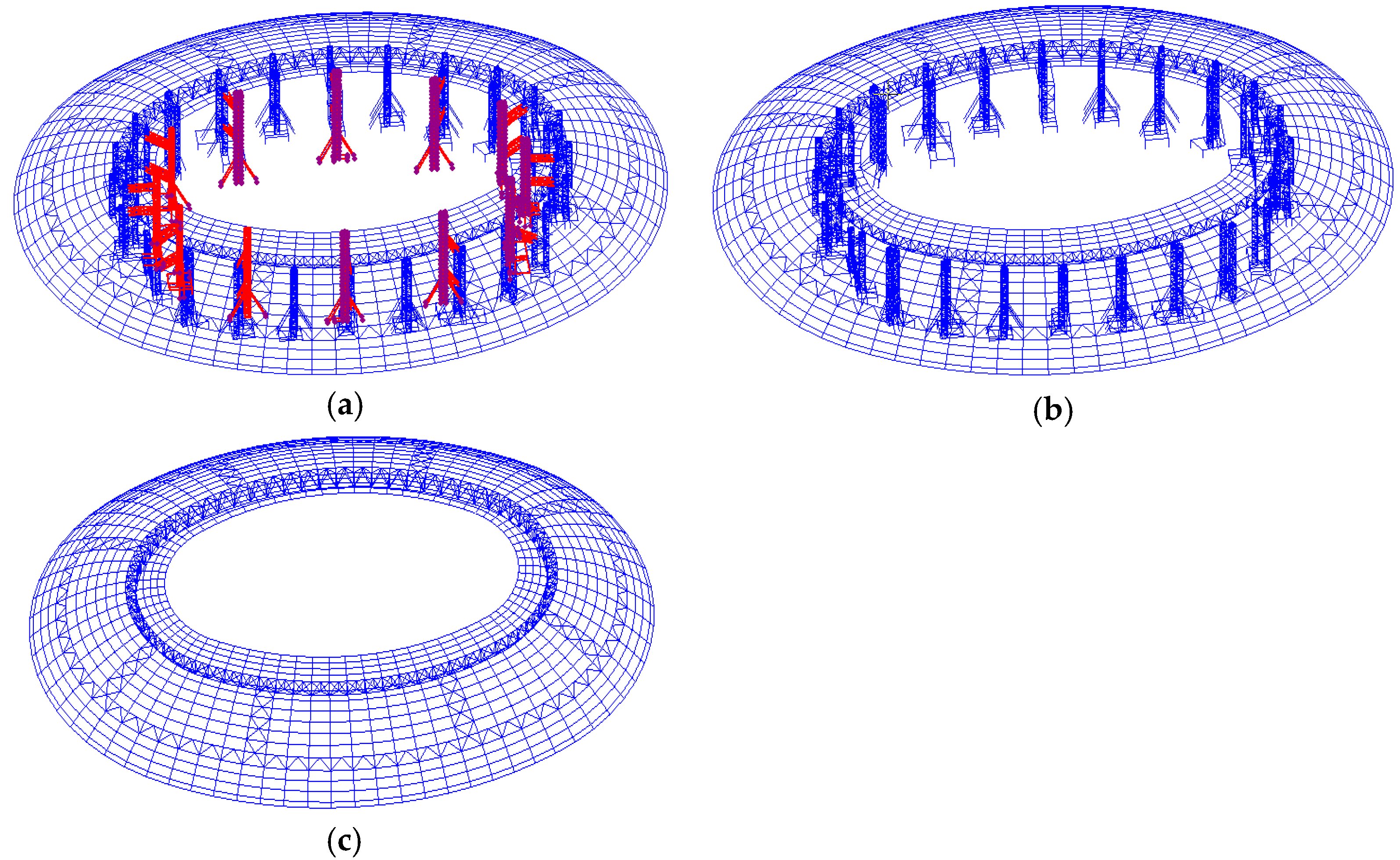
The highest point of the stands reaches 32 m above ground level. The architectural appearance preserves the style of the original stadium. The steel roof employs a spatial system comprising tension and compression rings. The inner ring of the roof incorporates a compression ring. The middle section contains an inverted triangular truss compression ring, while tension rings are installed at the tops of columns around the new stands. Seventy-two radial steel members connect the outer and middle rings, and another seventy-two variable cross-section box steel members link the middle and inner rings. Together, these circumferential and radial members constitute the roof’s main structural system. Project renderings, on-site construction and the unloading process of the steel roof are illustrated in Figure 2.
The unloading of the Shenzhen Stadium’s long-span steel roof comprises three stages: CS9 (inner ring unloading), CS10 (temporary support removal and static placement) and CS11 (middle ring unloading), as shown in Figure 3.

4.2. Determination of Monitoring Points and Establishment of a Monitoring System

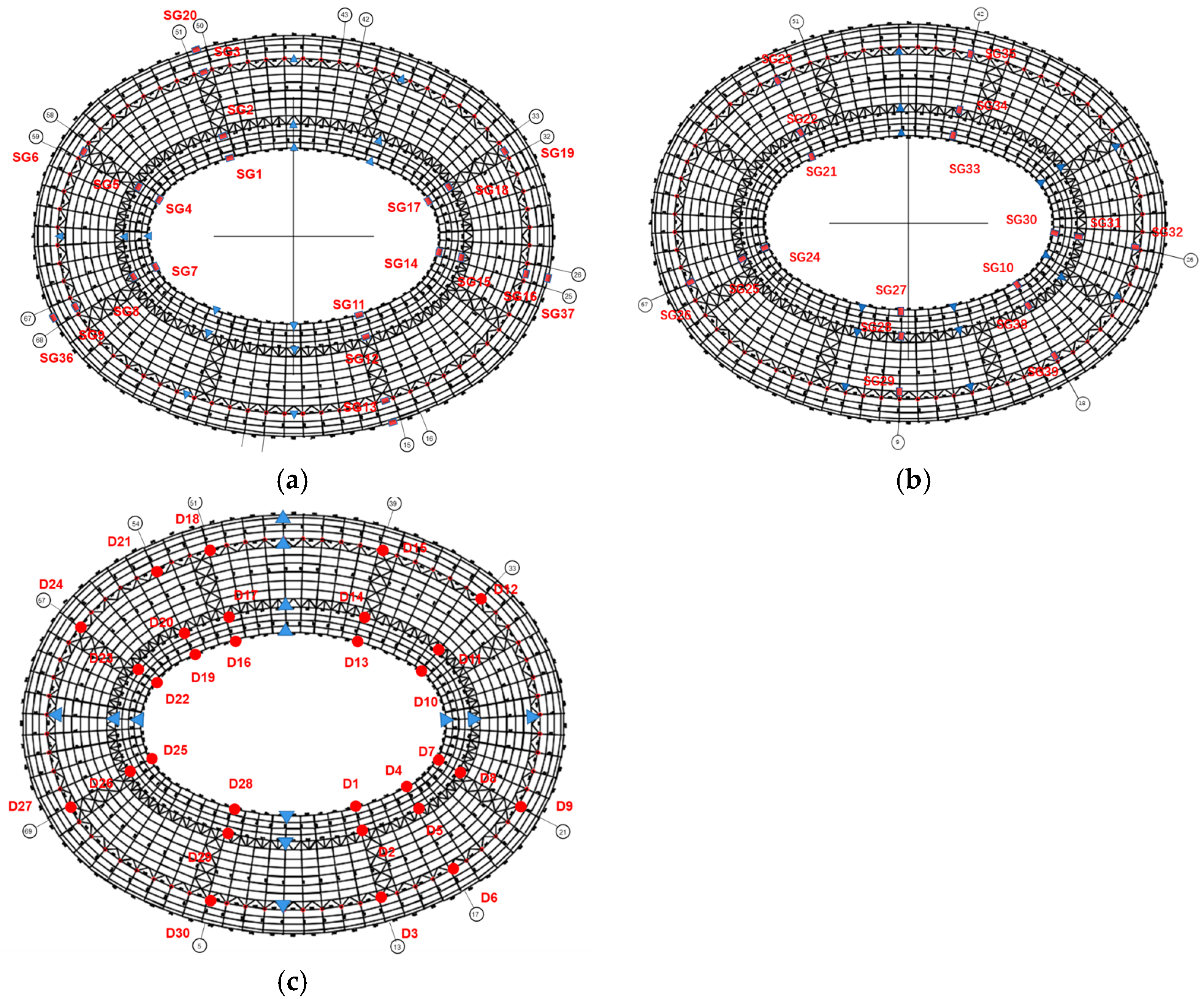
Overall, 21 circumferential measurement points were uniformly arranged across the three elliptical ring beams and the support ring beam of Shenzhen Stadium. Of these, six points were placed on each of the inner, middle and support ring beams, positioned near the centres of the long and short axes and the transition regions between them. As the outer ring beam exerted relatively limited influence on the overall structure, only three points were installed here. Further, 18 radial measurement points were arranged, with three points positioned on each of the six selected radial steel members. These six monitored members were distributed along the long axis, short axis and elliptical transition regions. Thirty displacement monitoring points were installed on the steel roof, with three points placed on each of 10 selected radial members, uniformly distributed across the elliptical regions. The layout of stress and displacement monitoring points on the steel roof is illustrated in Figure 4.
A vibrating wire strain gauge was employed to monitor strain in structural components. Notably, this sensor offers a measurement range of ±3000 µε, a resolution of 1 µε and an accuracy of ±0.5% of full scale (FS). It exhibits strong long-term stability, with annual drift below 0.1% FS and linearity exceeding 0.5% FS. Designed for extended deployment, the sensor has a service life of approximately 15 years. Its core specifications fully satisfy monitoring requirements, rendering data acquisition errors negligible.
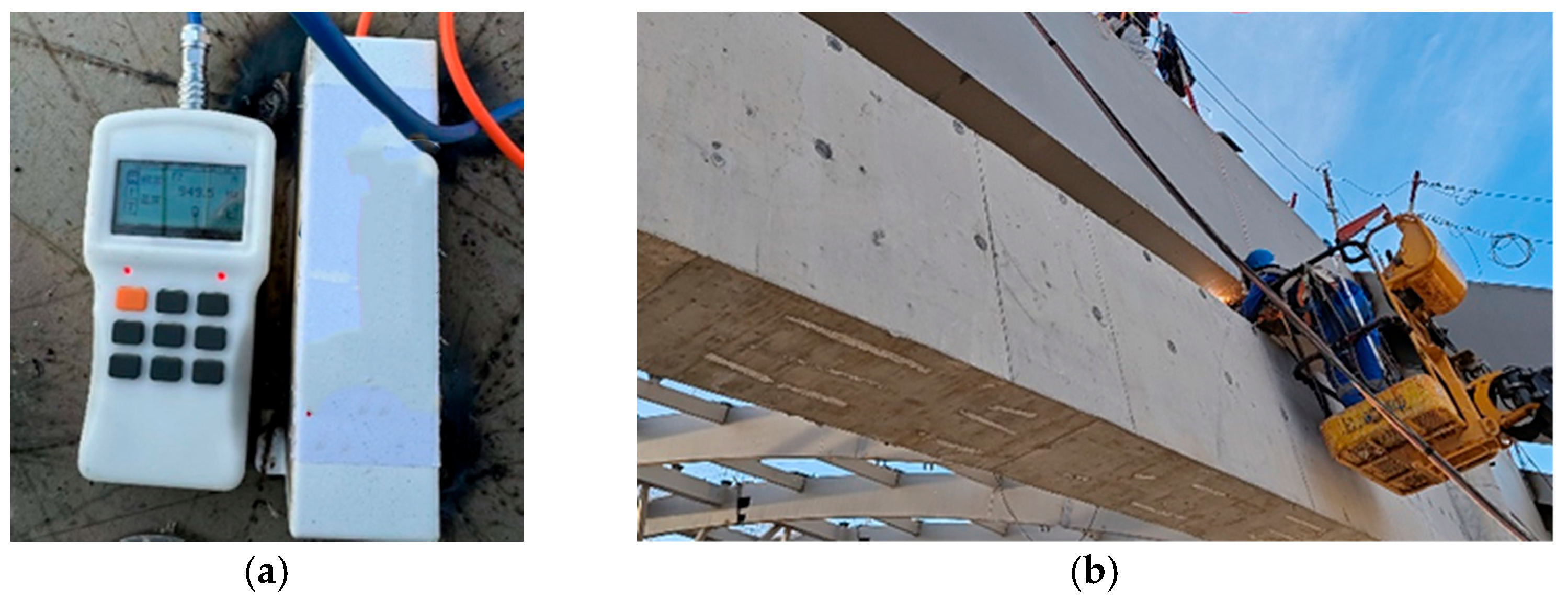
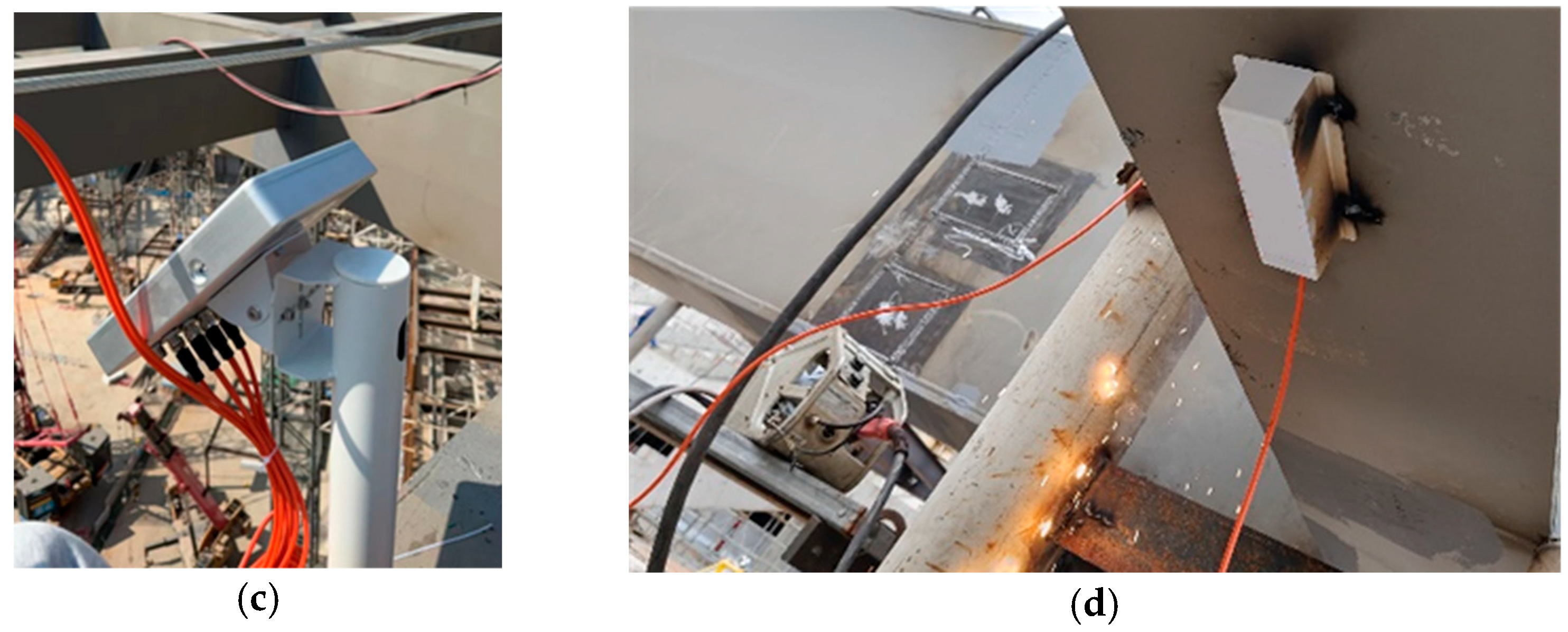
The stress sensor was mounted on both the upper and lower flanges of the steel beam at each measurement point. Twelve acquisition units were deployed, each tasked with collecting stress–strain monitoring data from a region comprising six radial steel beams. The on-site sensor installation and acquisition unit layout are depicted in Figure 5. During routine construction, monitoring data were acquired every 60 min, with the frequency increased to every 20 min during roof unloading.
The acquired monitoring data were continuous and verified through manual screening to confirm the absence of errors or interruptions. Future research will explore advanced algorithms for denoising and prediction, with the probabilistic mixture model framework proposed by Zhao et al. identified as a promising candidate for interpretable modelling, clustering and physical system data prediction [27].

4.3. Stiffness Monitoring

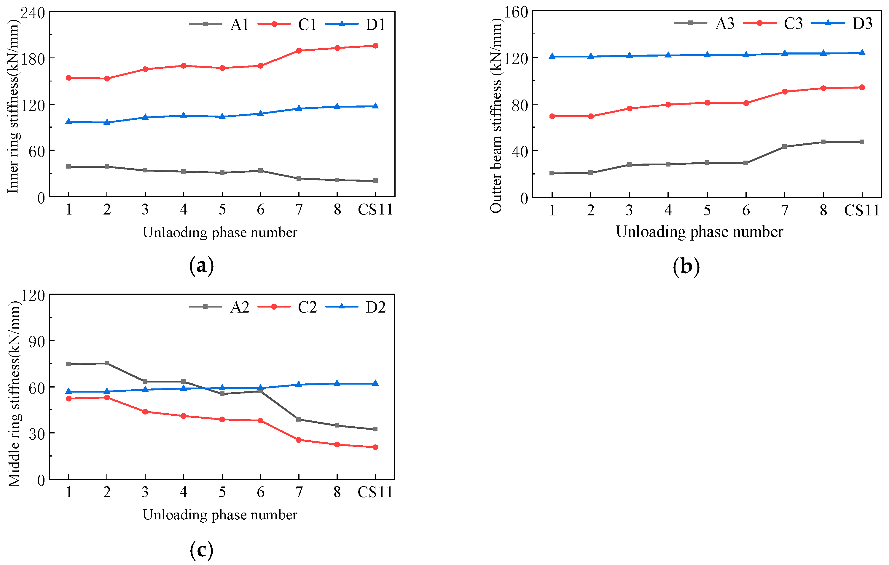
Due to the hysteresis effect caused by internal force redistribution following construction, internal stresses change gradually over time. To reflect the actual stiffness, recent monitoring data from the corresponding phase must be used, thereby eliminating the influence of this effect. Based on this, monitored stress and displacement values are converted into ring beam stiffness, and the variation in stiffness across construction stages is depicted in Figure 6 and Figure 7.
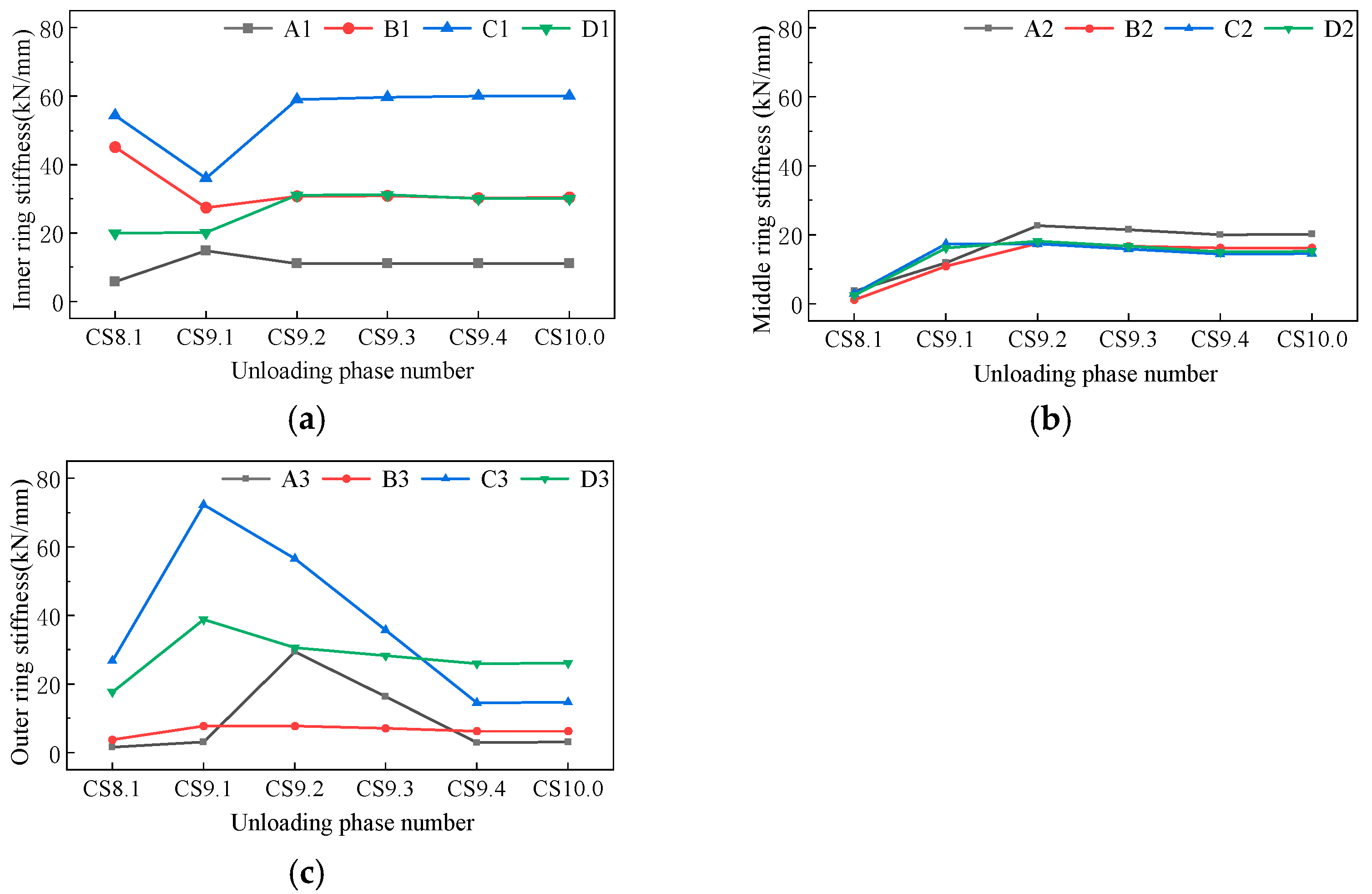
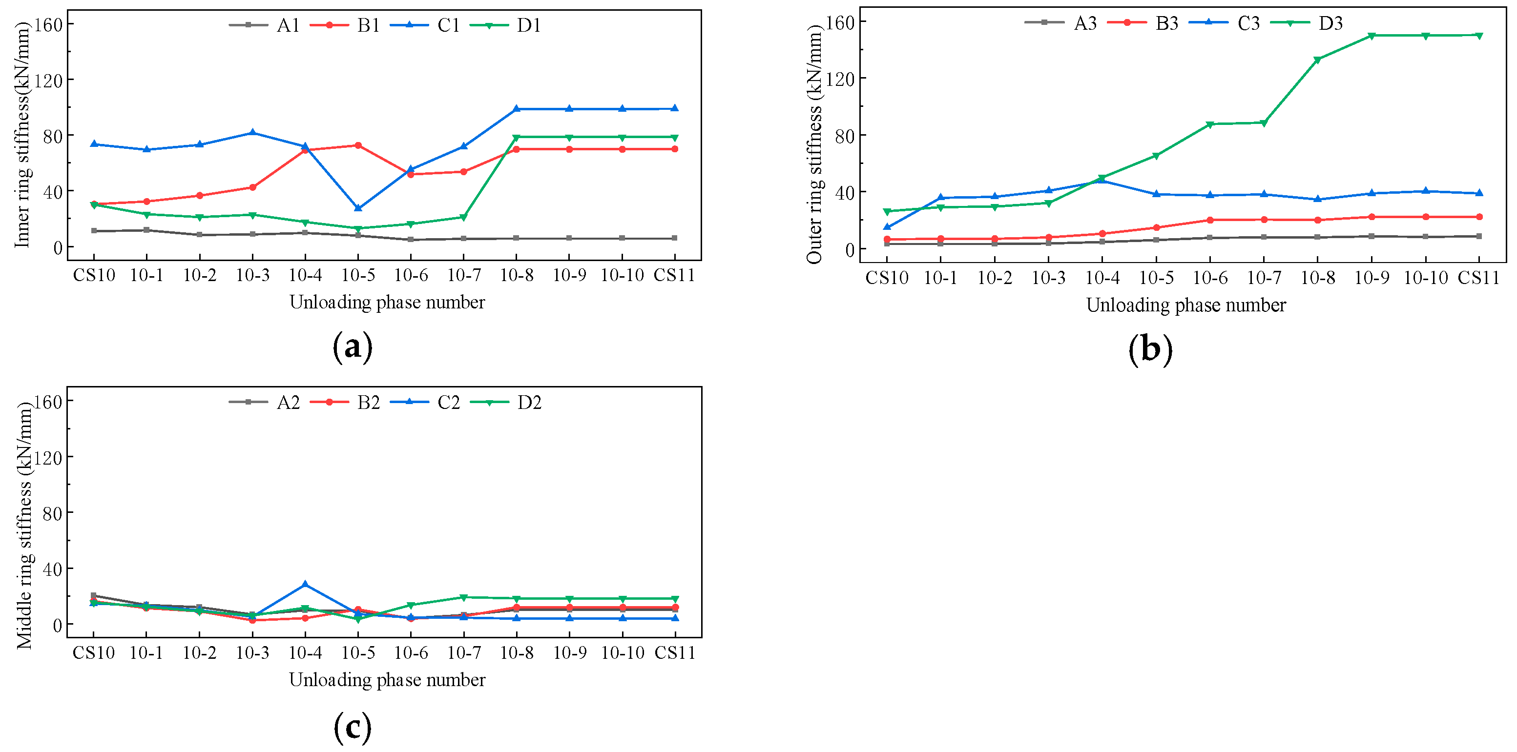
A finite element model was developed to simulate the progressive dismantling of the inner ring and central ring falsework. The model was constructed using beam elements, with material properties assigned based on Q420B steel. Boundary conditions were defined to match the actual structural constraints at each construction stage, and all joints were modelled as rigid connections. The mesh size was selected empirically, with each element measuring 0.25 m. Figure 8 and Figure 9 depict the simulated stiffness variation.
Although numerical discrepancies were observed between the simulated and monitored data, both exhibited the same overall distribution pattern, with stiffness values lower along the roof’s major axis and higher along the minor axis. This consistency demonstrates the feasibility of using monitoring data to characterise the spatial stiffness evolution of the ring beam before and after inner ring falsework unloading.
During falsework unloading, the monitored stiffness values of the three ring beams exhibit distinct changes at specific unloading stages. In particular, notable variations occur between the second and third monitoring intervals for the inner ring and between the sixth and eight intervals for the middle ring. Based on these changes, the time at which the ring beams enter the self-bearing state can be determined.

4.4. Self-Bearing Optimisation

Using FEM to simulate the progressive cutting and removal of the inner ring falsework. The cutting increment was defined as 20 cm, with each unloading stage manually defined. After the inner ring falsework and temporary supports were removed, the steel roof was fully supported by the middle ring falsework. Consequently, unloading the middle ring falsework caused notable internal force redistribution. Accordingly, the middle ring falsework was unloaded in 10 steps: 40 mm per cut for the first six steps and 30 mm for the last four. At the 11th unloading stage, the falsework was fully removed, marking the transition to construction stage CS11. This simulated unloading sequence is referred to as the Simulation Scheme.
Further, an optimised unloading scheme was established based on the Simulation Scheme. For the inner ring falsework unloading stage, the cutting increment was set to 35 cm, with the third cut fully removing the falsework. In the optimised middle ring unloading process, the first two cuts were at 60 cm each, followed by four cuts at 45 cm, and final two cuts at 60 cm. This optimised unloading process is referred to as the optimisation scheme.
To control spatial stiffness fluctuations in the ring beam during construction, accounting for the time-dependent effects of construction sequencing and nonlinear local stiffness contributions, defining an indicator for the stiffness variation rate at each stage and minimising it to reduce overall stiffness variation are essential. Regulating stiffness evolution at each stage can effectively suppress spatial stiffness fluctuations in the ring beam throughout the construction process.
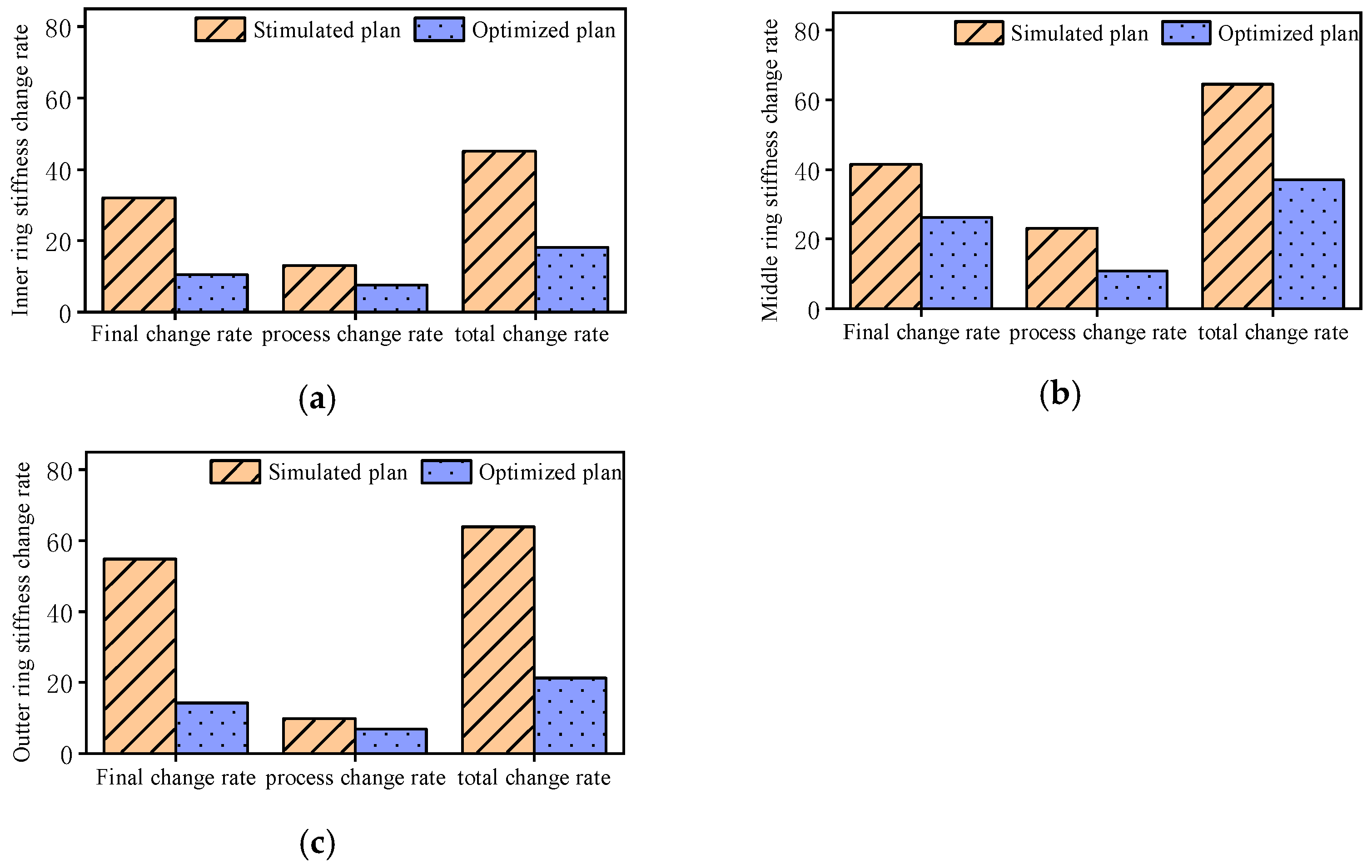
A systematic comparative analysis was performed to evaluate stiffness variation in the three ring beams. To this end, Figure 10 and Figure 11 display the final, process and total stiffness change rates for the three ring beams under both unloading schemes, based on computed data, calculated stiffness indicators and comparison curves.
These results indicate that the optimised scheme performs notably better when both final and process change rates are elevated. Specifically, it improves the service-phase self-bearing state by lowering the final change rate and enhances the unloading-phase self-bearing state by reducing the process change rate.
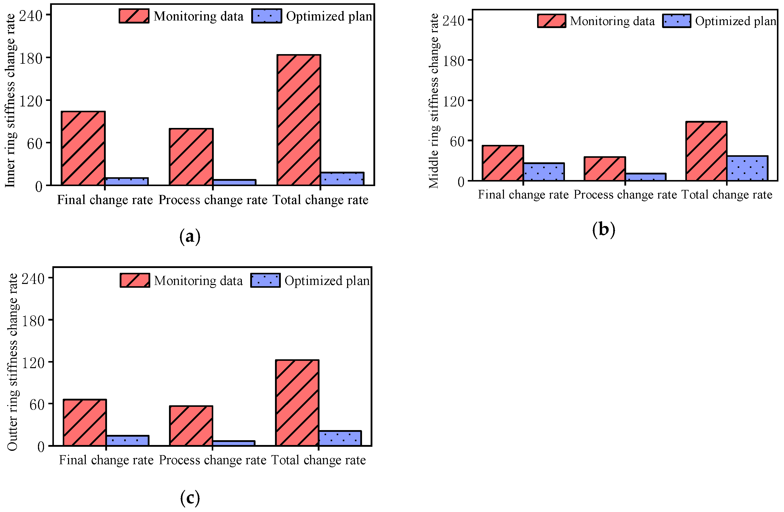
In both the simulation and optimisation schemes, the indicators of stiffness change rate for the three ring beams were calculated by summing all non-zero stiffness change values during the inner and middle ring falsework unloading stages. However, measured stiffness data for regions B1–B3 were unavailable. To ensure consistency, the change rate contributions from these regions were excluded from the optimisation scheme prior to comparison with the actual monitoring data. Accordingly, comparative bar charts illustrating the stiffness change rates for the three ring beams during inner ring unloading are presented in Figure 12 and Figure 13.
Comparison with the actual unloading scheme used at Shenzhen Stadium revealed that the optimised scheme considerably reduced the stiffness change rate during inner ring falsework unloading. During middle ring falsework unloading, the optimisation had a limited impact on the final change rate but notably improved the process change rate. These findings demonstrate that the initial unloading scheme proposed for Shenzhen Stadium has considerable room for optimisation, indicating ongoing potential for improving unloading practices in real-world construction projects.
The stiffness monitoring and unloading optimisation method presented in this study yields the following engineering recommendations:
  • A method is introduced to derive axial force vector sums at symmetric points of the ring beam based on on-site stress and displacement data. By installing strain gauges and displacement monitoring prisms on the steel roof structure, mechanical parameters such as stress and displacement at critical locations can be continuously monitored and fed back during construction, thereby ensuring structural safety.
  • The stiffness variation rate indicator introduced in this study provides a basis for optimising the unloading process in practical engineering applications. Increasing the single-cut unloading height of the falsework reduces the spatial stiffness variation rate of the unloading ring beam and mitigates the effects of internal force redistribution on the steel roof structure during unloading, thereby refining the construction process.

5. Conclusions

To address stiffness variation in long-span steel roof structures with spatial ring beams as the primary load-bearing element, this study systematically elucidated the formation mechanism of ring beam stiffness, evaluated the self-bearing state of the steel roof during unloading and proposed optimisation and control strategies based on theoretical analysis, numerical simulation and structural health monitoring. These findings offer practical guidance for similar engineering applications. The primary research findings are summarised as follows:
  • The study established layout principles for stress and displacement monitoring points in steel roof structures with ring beams as the core load-bearing element. Building on the definition of ring beam stiffness, a theoretical method for determining global stiffness was derived. Additionally, a comprehensive stiffness monitoring approach based on monitored internal force and displacement data were proposed.
  • The concept of non-dimensionalisation was employed to convert absolute stiffness changes between adjacent construction stages into stiffness change rates, thereby more clearly capturing the trend in stiffness evolution during the self-bearing process. Two unloading schemes were formulated, each associated with a corresponding finite element model. This indicator of stiffness change rate was then applied to complete the optimisation feedback for the structural self-bearing process.
  • A monitoring system was deployed at Shenzhen Stadium to track stress, displacement and stiffness-related mechanical indicators. Comparison with the optimised scheme from the finite element model revealed that the implemented unloading plan had potential for further improvement in self-bearing performance, offering valuable guidance for similar future projects.
After the implementation of the proposed optimisation scheme, the structural stiffness variation rate was markedly reduced relative to the original unloading plan. Specifically, reductions of 26%, 47% and 17% were achieved in the inner, middle and outer rings, respectively. In particular, the optimised scheme produced a smoother stiffness evolution profile for the ring beam during force redistribution, with a notably lower fluctuation amplitude across all monitoring points. These results provide strong evidence for the effectiveness of the optimised approach in controlling the redistribution of internal forces.
This study has certain limitations that indicate directions for future research:
  • When verifying the mechanism of spatial stiffness formation in the ring beams, the construction simulation of the Shenzhen Stadium considered only the structural self-weight load. In practice, monitoring data from the stadium clearly show that temperature effects significantly influence the internal force distribution of the steel structure. Future work could further examine the influence of temperature effects on the spatial stiffness of the ring beams.
  • The optimisation scheme proposed in this study focuses solely on the unloading stage. However, due to the path-dependent and time-dependent effects of the construction process, the assembly and closure sequence of the ring beams considerably affect the spatial stiffness and self-bearing state before unloading. Subsequent research could refine the finite element model to consider various ring beam closure scenarios, analyse the self-bearing state of the steel roof under these conditions and explore the influence of closure sequences on self-bearing behaviour.

Author Contributions

Conceptualisation, W.L., C.Y. and J.T.; methodology, C.Y. and H.X. (Hang Xiong); validation, H.X. (Huasheng Xia) and R.M.; formal analysis, Y.X.; investigation, C.Y. and H.X. (Hang Xiong); resources, J.T., W.L. and W.H.; data curation, W.L. and C.Y.; writing—original draft preparation, C.Y. and H.X. (Hang Xiong); writing—review and editing, W.L., C.Y. and Y.X.; supervision, W.L.; project administration, W.L. and J.T.; funding acquisition, W.L., J.T. and W.H. All authors have read and agreed to the published version of the manuscript.

Funding

This research was funded by the National Key Research and Development Programme of China [grant numbers 2024YFC3810504], National Natural Science Foundation of China [grant numbers 52122804, 52438004, 52378296] and the Higher Education Stable Support Program of Shenzhen [grant number GXWD20220811163144001].

Data Availability Statement

The data presented in this study are available on request from the corresponding author. The data are not publicly available due to commercial privacy.

Conflicts of Interest

Huasheng Xia and Rongying Mao were employed by the company China Construction Steel Structure Co., Ltd. The remaining authors declare that the research was conducted in the absence of any commercial or financial relationships that could be construed as a potential conflict of interest.

References

  1. Ngamkhanong, C.; Kaewunruen, S.; Costa, B.J.A. State-of-the-Art Review of Railway Track Resilience Monitoring. Infrastructures 2018, 3, 3. [Google Scholar] [CrossRef]
  2. Kaewunruen, S.; Sresakoolchai, J.; Zhou, Z. Sustainability-Based Lifecycle Management for Bridge Infrastructure Using 6D BIM. Sustainability 2020, 12, 2436. [Google Scholar] [CrossRef]
  3. Chucheepsakul, S.; Phungpaigram, B. Elliptic Integral Solutions of Variable-Arc-Length Elastica under an Inclined Follower Force. ZAMM—J. Appl. Math. Mech. Z. Angew. Math. Mech. 2004, 84, 29–38. [Google Scholar] [CrossRef]
  4. Sibanda, K.; Kaewunruen, S. Life Cycle Assessment of Retrofit Strategies Applied to Concrete Infrastructure at Railway Stations Exposed to Future Extreme Events. In Proceedings of the RILEM Spring Convention and Sustainable Materials, Systems and Structures Conference: RILEM RMSS 2019, Rovinj, Croatia, 20–22 March 2019; RILEM Publications SARL: Paris, France, 2019; pp. 168–175. [Google Scholar]
  5. Ngamkhanong, C.; Kaewunruen, S.; Baniotopoulos, C. Nonlinear Buckling Instabilities of Interspersed Railway Tracks. Comput. Struct. 2021, 249, 106516. [Google Scholar] [CrossRef]
  6. Kaewunruen, S.; Ngamkhanong, C.; Baniotopoulos, C. Resilience and Robustness of Long-Span and Tall Structures under Extreme Actions. Front. Built Environ. 2020, 6, 67. [Google Scholar]
  7. Ben, N.; Chen, Z. Simulation Analysis of the Steel Roof of the Tianjin Grand Theatre in the Unloading Process. In Proceedings of the 2013 Fourth International Conference on Digital Manufacturing & Automation, Qingdao, China, 29–30 June 2013; pp. 1203–1206. [Google Scholar]
  8. Zhou, G.; Zhang, J.; Liu, J.; You, G.; Wang, Y. Construction Simulation Analysis of Steel Structure for Hangzhou Olympic Sports Center Main Stadium. Constr. Technol. 2014, 43, 1–5. [Google Scholar]
  9. Liu, H.; Zhou, R.; Sheng, X.; Xu, J.; Xu, F.; Wang, Y. Nonlinear-Response Study on the Two Beams Coupled by the Multiple Nonlinear Elements with the Cubic Stiffness. Nonlinear Dyn. 2024, 112, 19735–19757. [Google Scholar] [CrossRef]
  10. Xu, C.; Ye, L.; Pan, S.; Luo, W. Integrated Time-Dependent Analysis of a Hydraulic Structure on Soft Foundations during Construction. Water 2024, 16, 1375. [Google Scholar] [CrossRef]
  11. Dai, P.; Tang, J. Research on Construction Monitoring Techniques for Cable Replacement of the Cable-Stayed Bridge. Res. J. Appl. Sci. Eng. Technol. 2013, 6, 3202–3208. [Google Scholar]
  12. Huang, W.; Jin, T.; Zhu, Z.; Cai, X.; Cai, T.; Huang, Y.; Zhou, M.; Liu, Q.; Shen, Y. Monitoring and Analysis of Construction Process for Reconstruction of Existing Cantilever Roof Structure in a Stadium. Spat. Struct. 2023, 29, 62–68. (In Chinese) [Google Scholar]
  13. Wu, J. Full Process Analysis and Application of Steel Structure Jacking and Unloading in a Stadium. Prog. Steel Build. Struct. 2021, 23, 119–128. (In Chinese) [Google Scholar]
  14. Prem, K. A Review of Developments in Steel: Implications for Long-Span Structures. Trans. Indian Inst. Met. 2021, 74, 1055–1064. [Google Scholar] [CrossRef]
  15. Wang, H.; Yang, F.; Shen, B.; Ma, K.J.; Zheng, T.H.; Fan, Y.H. Construction Process Analysis for a Multi-Story Building Structure with Floors Slab of Long-Span. Civ. Eng. J. 2019, 28, 404–419. [Google Scholar] [CrossRef]
  16. Chen, K.; Yuan, G.; Wang, L.; Zhang, W.; Wang, X. Research on Construction Monitoring of Large-Span Steel Pipe Truss Structure. Open J. Civ. Eng. 2019, 09, 255–267. [Google Scholar] [CrossRef]
  17. Furukawa, S.; Iwami, R.; Kimura, Y. Development of an Environmentally Friendly Steel Structural Framework: Evaluation of Bending Stiffness and Yield Bending Moment of Cross-Laminated Timber Slab–H-Shaped Steel Composite Beams for Component Reuse. Sustainability 2025, 17, 2073. [Google Scholar] [CrossRef]
  18. Shao, J.H.; Duan, M.J.; Yang, W.; Li, Y.Z. Research on the Critical Technique of Synchronous Rotation Construction with Large Angle for T-shape Curve Rigid Frame Bridge. Sci. Rep. 2022, 12, 1530–1545. [Google Scholar] [CrossRef] [PubMed]
  19. Shao, J.H.; Wang, Z.H.; Tao, G.Y. Research on the Unloading Process of Long-Span Steel Roof and the Design of Temporary Bracing Structure. Adv. Mater. Res. 2011, 163, 251–258. [Google Scholar] [CrossRef]
  20. Shi, N.Q.; Shi, Z.J.; Tong, C.C.; Jin, X.G. Construction Mechanics of Ultra Deep Ventilation Shaft in Subway Station Under Complex Engineering Environment. In Proceedings of the 2019 International Conference on Energy, Environmental and Civil Engineering (EECE 2019), Wuhan, China, 23–24 June 2019; pp. 264–270. [Google Scholar]
  21. Yang, W.; Hong, G.; Wang, M.; Yang, G.; Zhang, G.; Wang, S.; Duan, Y.; Ge, J.; Zhou, W. Simulation Analysis of the Entire Construction Process of a Multi-Story Large Cantilever Steel Structure. J. Build. Struct. 2012, 33, 87–94. [Google Scholar]
  22. Ren, L.; Yuan, C.L.; Li, H.N.; Yi, T.H. Structural Health Monitoring System Developed for Dalian Stadium. Int. J. Struct. Stab. Dyn. 2016, 16, 1640018. [Google Scholar] [CrossRef]
  23. Huang, Z.Y.; Wang, M.; Cao, W.; Yan, Q. Research on Unloading Technology for the Long-Span Open Single-Layer Arch-Shell Steel Roof of Beijing Workers’ Stadium. Build. Struct. 2023, 53, 26–30. [Google Scholar]
  24. Zhou, G.P.; Li, A.Q.; Li, N.; Li, J.H. Design and Analysis of the Health Monitoring System for the Steel Arch of the Main Stadium Roof in Nanjing Olympic Sports Center. Appl. Mech. Mater. 2016, 858, 3–9. [Google Scholar] [CrossRef]
  25. Zhao, F.W.; Fei, G. Application and Research of Steel Structure Construction Monitoring of Costa Rica State Stadium Canopy with Measurement Robot. Energy Procedia 2011, 13, 2794–2801. [Google Scholar] [CrossRef]
  26. Huang, T.R.; Wu, J.J.; Deng, X.Y.; Bai, G.B.; Zhu, Z.Y.; Zhang, J. Research and Application of Monitoring Technology for De-Propping Stress and Deformation of Lusail Stadium Steel Structure. Spat. Struct. 2024, 30, 47–54. [Google Scholar]
  27. Zhao, H.; Zhang, X.; Ding, Y.; Guo, T.; Li, A.; Soh, C.K. Probabilistic Mixture Model Driven Interpretable Modeling, Clustering, and Predicting for Physical System Data. Eng. Appl. Artif. Intell. 2025, 160, 112069. [Google Scholar] [CrossRef]
Figure 1. Schematic illustrating internal forces and displacements of the curved beam at section m and its centrally symmetric section after closure. (a) Top view of the section m isolation body and distribution of axial force and displacement. (b) Cross-sectional profile of the partition at section m.
Buildings 15 04293 g001
Figure 2. Finite element models and site photographs of the Shenzhen Stadium steel roof structure. (a) Overall structural view of Shenzhen Stadium. (b) Finite element model of the complete structure. (c) On-site construction and installation of the steel roof. (d) Formwork cutting and unloading during on-site roof construction.
Buildings 15 04293 g002
Figure 3. Unloading stages of the Shenzhen Stadium’s long-span steel roof. (a) Unloading of the inner ring (CS9). (b) Removal of temporary supports (CS10). (c) Unloading of the middle ring (CS11).
Buildings 15 04293 g003
Figure 4. Layout diagrams of stress and displacement monitoring points on the steel roof. (a) Circumferential stress monitoring point layout. (b) Radial stress monitoring point layout. (c) Displacement monitoring point layout.
Buildings 15 04293 g004
Figure 5. Pictures of on-site installation of strain sensors and acquisition units at Shenzhen Stadium. (a) Top view of elevation sensor installation. (b) Side view of circumferential sensor installation. (c) Layout of strain monitoring and acquisition units. (d) Side view of radial sensor installation.
Buildings 15 04293 g005aBuildings 15 04293 g005b
Figure 6. Monitored stiffness of the three ring beams during inner ring falsework unloading. (a) Inner ring beam stiffness. (b) Middle beam stiffness. (c) Outer ring beam stiffness.
Buildings 15 04293 g006
Figure 7. Monitored stiffness of the three ring beams during central ring frame unloading. (a) Inner ring beam stiffness. (b) Middle beam stiffness. (c) Outer ring beam stiffness.
Buildings 15 04293 g007
Figure 8. Simulated stiffness of the three ring beams during inner ring falsework unloading. (a) Inner ring beam stiffness. (b) Middle beam stiffness. (c) Outer ring beam stiffness.
Buildings 15 04293 g008
Figure 9. Simulated stiffness of the three ring beams during central ring frame unloading. (a) Inner ring beam stiffness. (b) Middle beam stiffness. (c) Outer ring beam stiffness.
Buildings 15 04293 g009
Figure 10. Stiffness change rates of the three ring beams under different inner ring falsework unloading schemes. (a) Comparison of stiffness change rates in the inner ring. (b) Comparison of stiffness change rates in the middle ring. (c) Comparison of stiffness change rates in the outer ring.
Buildings 15 04293 g010
Figure 11. Stiffness change rates of the three ring beams under different middle ring falsework unloading schemes. (a) Comparison of stiffness change rates in the inner ring. (b) Comparison of stiffness change rates in the middle ring. (c) Comparison of stiffness change rates in the outer ring.
Buildings 15 04293 g011
Figure 12. Comparison of stiffness change rates of the three ring beams under two unloading schemes for inner ring bearing. (a) Stiffness change rate comparison for the inner ring beam. (b) Stiffness change rate comparison for the central ring beam. (c) Stiffness change rate comparison for the outer ring beam.
Buildings 15 04293 g012
Figure 13. Comparison of stiffness change rates of the three ring beams under two unloading schemes for the inner ring frame. (a) Stiffness change rate comparison for the inner ring beam. (b) Stiffness change rate comparison for the central ring beam. (c) Stiffness change rate comparison for the outer ring beam.
Buildings 15 04293 g013
Disclaimer/Publisher’s Note: The statements, opinions and data contained in all publications are solely those of the individual author(s) and contributor(s) and not of MDPI and/or the editor(s). MDPI and/or the editor(s) disclaim responsibility for any injury to people or property resulting from any ideas, methods, instructions or products referred to in the content.