Article

Effects of Joint Configurations on Shear Behavior of Prefabricated Segmental Cap Beams

1
Jiangxi Gan Yue Expressway Co., Ltd., Nanchang 330025, China
2
Jiangxi Changtong Expressway Co., Ltd., Nanchang 330025, China
3
School of Infrastructure Engineering, Dalian University of Technology, Dalian 116024, China
*
Author to whom correspondence should be addressed.
Buildings 2025, 15(23), 4286; https://doi.org/10.3390/buildings15234286
Submission received: 22 September 2025 / Revised: 26 October 2025 / Accepted: 6 November 2025 / Published: 26 November 2025
(This article belongs to the Special Issue Structural Vibration Analysis and Control in Civil Engineering)

Abstract

The joint configurations of prefabricated segmental cap beams exhibit considerable diversity in engineering applications. In recent years, combined shear key corbel connections have been increasingly adopted due to their advantages in prefabrication efficiency, rapid assembly, and favorable mechanical performance. Nevertheless, research on their ultimate shear capacity remains limited. To systematically assess the effects of joint configuration on shear performance, two types of cap beam models were developed reflecting engineering loading characteristics dominated by positive shear with secondary negative shear effects: a shear key model (SK1) and two keyed corbel models (SK2 and SK3), subjected to positive and negative loading, respectively. A full nonlinear static analysis with progressive loading to failure was conducted to obtain cracking load, ultimate capacity, stress distribution, deflection, and damage evolution. The results reveal that (1) all beams exhibited damage localization near adhesive joints, with shear–compression as the governing failure mode; (2) SK1 and SK2 achieved comparable shear capacities, whereas SK3 reached less than 30% of their ultimate strength; (3) SK2 attained the highest ultimate capacity, 1.07 times that of SK1; and (4) SK2 reached a maximum deflection of 3.24 mm, exceeding the other two by more than 29%. Overall, the keyed corbel configuration (SK2) demonstrated the most favorable comprehensive shear performance.

1. Introduction

In recent years, the cast-in-place concrete bridge construction method has been plagued by issues such as difficult construction scheduling, long construction cycles, and weather dependency, which not only increase construction costs but also exacerbate environmental pollution. To address the limitations of the cast-in-place method, prefabricated assembly technology has gradually been applied to urban bridge and highway engineering practices [1,2]. To address the excessive self-weight of monolithic precast large-cantilevered cap beams, technical solutions such as fully precast prestressed ultrahigh-performance concrete (UHPC) thin-walled cap beams [3,4] and partially precast composite cap beams [5,6] have been developed. However, in urban bridge construction, these cap beams often suffer from drawbacks such as excessive self-weight, large overall dimensions, and long cantilevers. These characteristics not only cause severe obstruction to urban road traffic but also present significant challenges for factory prefabrication as well as on-site transportation and hoisting.
Segmented precast prestressed concrete cap beam (SPPCCB) technology provides an efficient and economical solution to the challenges of transporting and hoisting prefabricated cap beams and has been successfully applied in numerous engineering projects. In practice, SPPCCBs primarily employ horizontal segmentation, where construction only involves handling the joint sections, without splicing or in situ casting [7,8]. Current research on the performance of prefabricated segmented cap beam joints mainly focuses on the effects of joint types and structural forms. Regarding joint types, experimental studies [9,10,11,12,13,14] have shown that SPPCCBs with epoxy joints exhibit significantly better mechanical performance than those with dry joints, with stiffness and bearing capacity closer to monolithic cast-in-place beams. However, epoxy joints still represent the structural weak point, resulting in markedly lower ultimate bearing capacity and ductility compared to cast-in-place structures, as well as frequent wide and localized cracking at the joints upon failure [15,16].
Regarding joint construction, commonly used joint forms include large-keyed, small-keyed, steel-keyed, and corbel-type joints. Specifically, large-keyed joints enhance shear performance by increasing the shear surface but require higher construction precision, while small-keyed joints are structurally simple but offer lower shear performance [17]. Steel-keyed joints improve force transfer through embedded steel components, though at a higher cost [18]; and corbel-type joints are widely used in practice due to their construction convenience but show a substantial reduction in ultimate bearing capacity and deformation [15,19]. However, existing research still lacks a systematic analysis of the shear failure mechanisms of different joint constructions and joint interface slippage, leading to reliance on empirical or overly conservative assumptions in design. Moreover, the uniform elements used in current studies have difficulty accurately simulating the complex damage processes in joint areas, particularly the coupled effects of concrete cracking, adhesive layer debonding, and keyed shear failure [20,21]. Therefore, future research should consider hybrid joint constructions and incorporate more precise analytical models to study their impact on mechanical performance, providing theoretical support for joint optimization design.
Current research has predominantly investigated epoxy joint types and single-keyed constructions of SPPCCBs, with limited attention given to the behavior of various keyed joint forms. Motivated by engineering practice, this study conducts nonlinear finite element analysis to examine the mechanical performance of SPPCCBs with different keyed joint constructions under concentrated loads applied at the beam top. The analysis focuses on damage evolution, mechanical behavior, and failure modes. The novelty of this study lies in the fact that, for the first time, a systematic nonlinear finite element comparative analysis is conducted on the mechanical behavior of “shear key + corbel” composite joints under different shear loading directions (positive and negative), revealing significant differences in failure modes, bearing capacity, and deformation capacity compared to traditional single shear key joints [22].

2. Component Design

This study focuses on a novel SPPCCB designed for a highway reconstruction and expansion project. The prototype component features an inverted T-shaped cross-section, where the cap beam is divided into two precast segments along the midspan using a combined corbel joint and shear keys, with an epoxy-bonded interface at the joint. To further investigate the mechanical performance of different joint configurations, two simplified component models were developed based on the prototype. The shear key (SK1) and keyed corbel (SK2, SK3) both follow a “three-segment transverse division” scheme. Besides the joint type, all other structural parameters remain identical between the three models. The overall calculated span of each model is 11,000 mm, with a height of 2750 mm, resulting in a height-to-span ratio of 1/4. The upper protruding section is referred to as the top web, with a thickness of 1600 mm and a height of 1650 mm. The lower section is termed the bottom flange, with a width of 3400 mm and a height of 1100 mm. The beam incorporates six straight prestressing strands (diameter: 15.2 mm, cross-sectional area: 180 mm2) symmetrically distributed along both sides of the internal section. The assembly method and structural dimensions are illustrated in Figure 1. For materials, beam segments are cast using C50 concrete, with longitudinal reinforcement steel consisting of HRB400 steel bars (diameters: 12 mm and 28 mm) and stirrups made of HRB400 steel bars (diameter: 16 mm). The epoxy joint configuration [23] and beam reinforcement details are shown in Figure 2.

3. Numerical Model

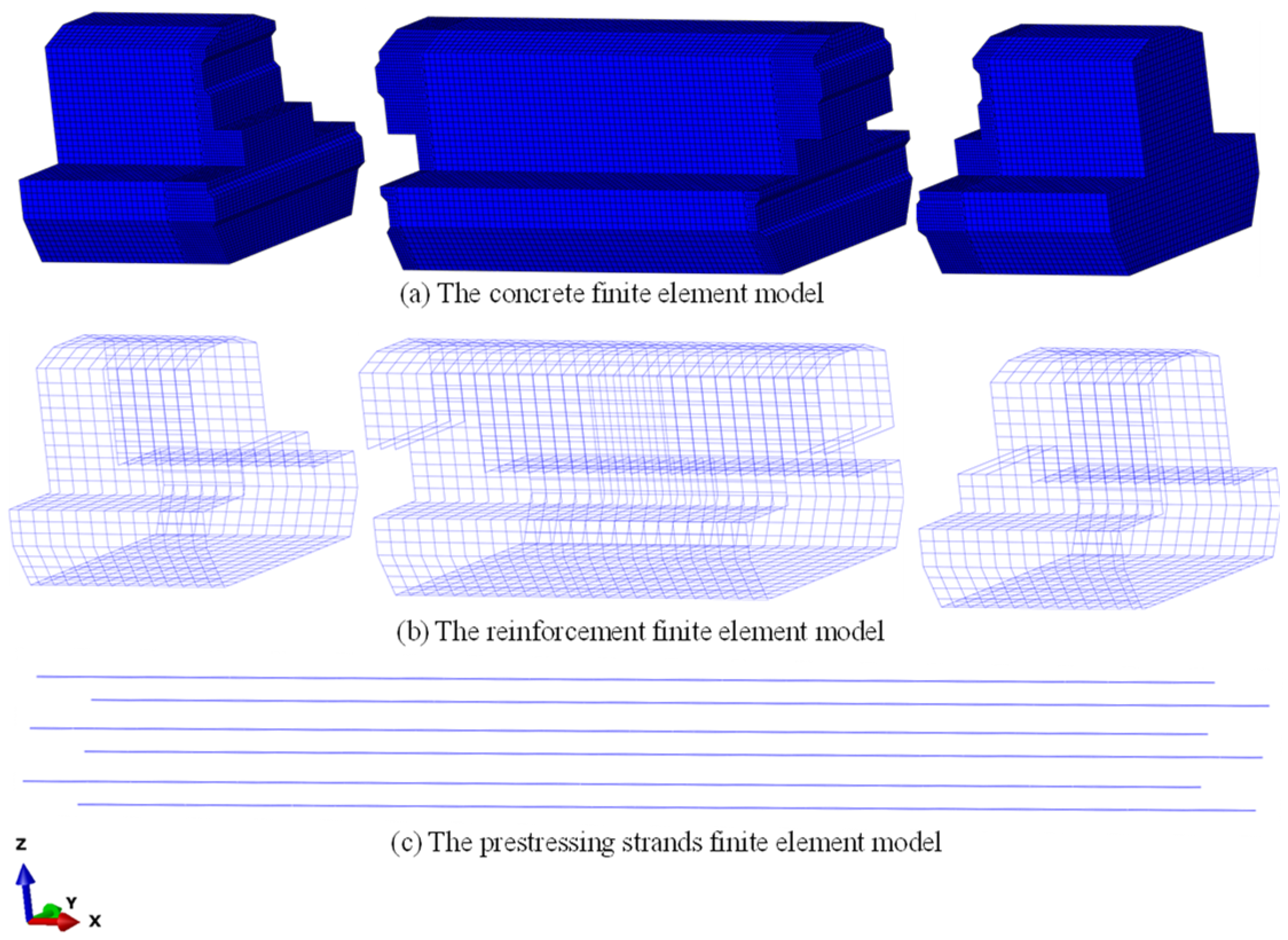
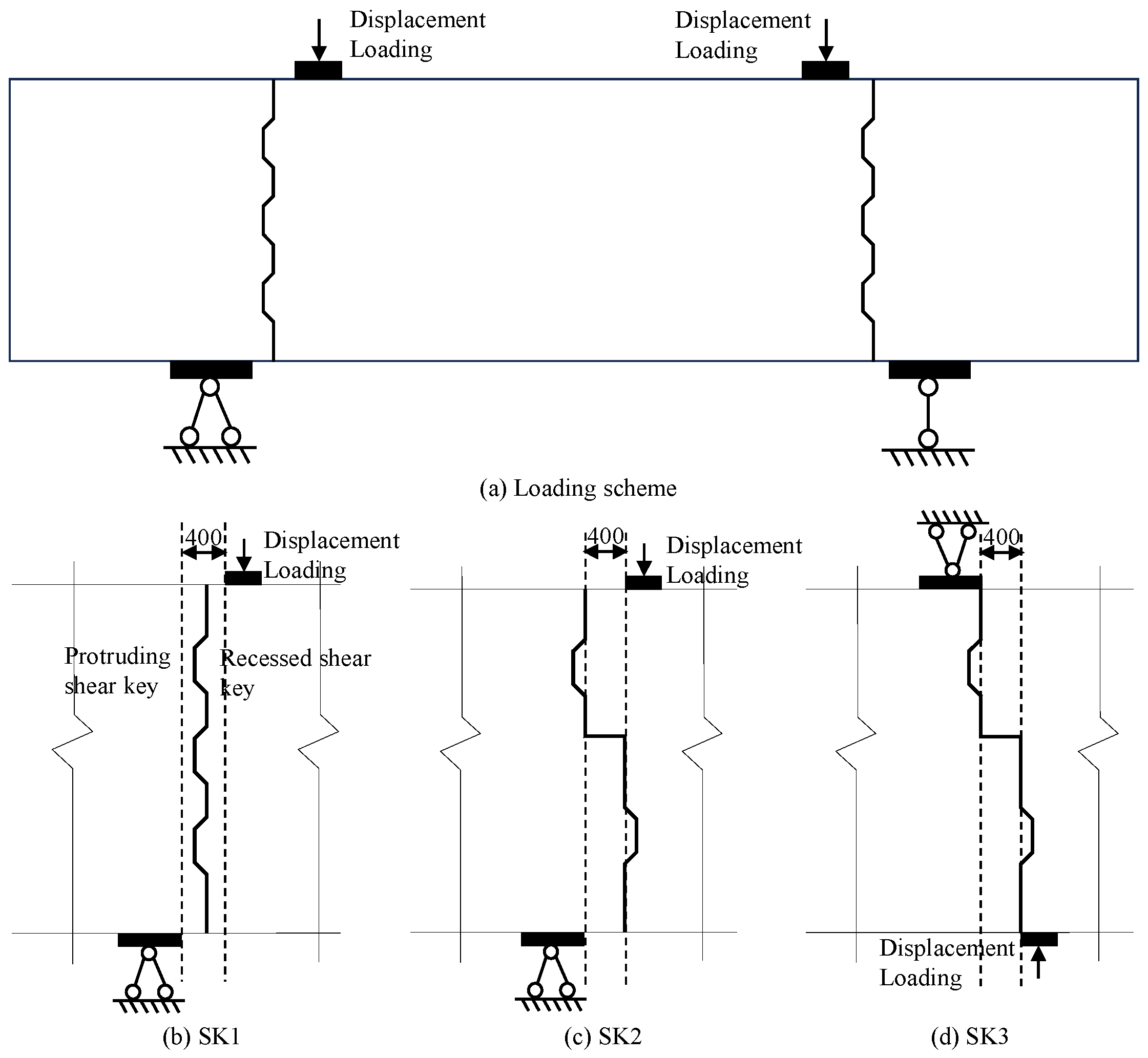
To investigate the shear performance of different joints, this study developed a numerical model in Abaqus (Figure 3) with the loading scheme illustrated in Figure 4. To enhance computational efficiency, a partitioned modeling approach was adopted, whereby each component was modeled independently. Concrete elements and bearing blocks were simulated using 8-node linear reduced integration elements (C3D8R), while reinforcement was modeled with 2-node 3D truss elements (T3D2) to capture axial behavior. Prestressing strands were represented by 2-node linear beam elements (B31) to properly account for bending effects during prestressing and loading. Interaction modeling was defined by embedded region constraints between reinforcement/strands and concrete to achieve composite action, together with tie constraints at the bearing block–concrete interfaces to establish rigid connections. The concrete constitutive behavior was represented using the Concrete Damage Plasticity (CDP) model, enabling simulation of stiffness degradation and damage evolution under complex loading conditions (parameters listed in Table 1), while reinforcement steel and strands were modeled with bilinear elastic–plastic constitutive laws based on the yield strengths and elastic moduli specified in Table 2.
The straight prestressing strands were tensioned using the cooling method, based on the principle of exploiting thermal expansion through the coupled effects of the temperature field and thermal expansion coefficient to emulate prestress application. This process induces contraction in the strands, which, constrained by the surrounding concrete, establishes an equivalent prestressed state in the component. To improve computational efficiency, transition meshes were applied in regions adjacent to the beam’s epoxy joints. This allowed local refinement of concrete elements in critical areas, with element sizes of 40 mm in the refined zones and 80 mm in non-refined zones. This meshing strategy effectively balances computational accuracy and efficiency by reducing redundant calculations. The complete finite element model development process is illustrated in Figure 5.

4. Comparative Analysis

According to the aforementioned loading configuration, the shear keys are subjected not only to vertical shear forces transmitted from the top loading point but also to additional bending moments, which differ significantly from the direct shear loading conditions described in references [27,28]. This discrepancy arises because, to ensure full utilization of the shear keys’ capacity in the SK2 model, the loading position had to be adjusted to the root region of the protruding shear keys, inevitably introducing additional moments. To mitigate the influence of this additional moment on numerical simulations, a constant 400 mm distance between the loading pads and supports was maintained across all three models (To ensure the shear key’s performance is fully utilized, the loading point must be positioned at the root of the key tooth, which corresponds to a distance of 400 mm, as illustrated in Figure 4c). The ultimate shear capacity of the prefabricated bent caps was approximately evaluated using the maximum support reaction force.

4.1. Crack Propagation and Failure Modes

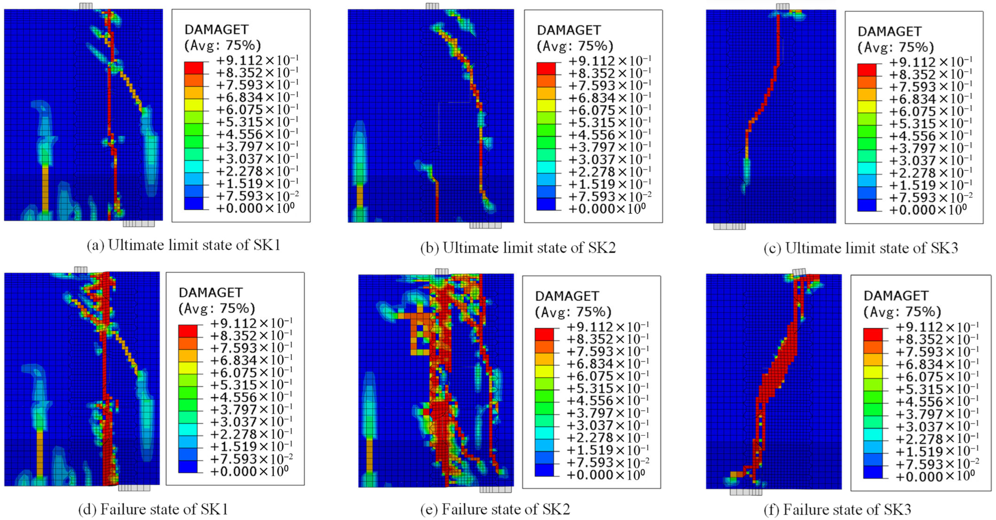
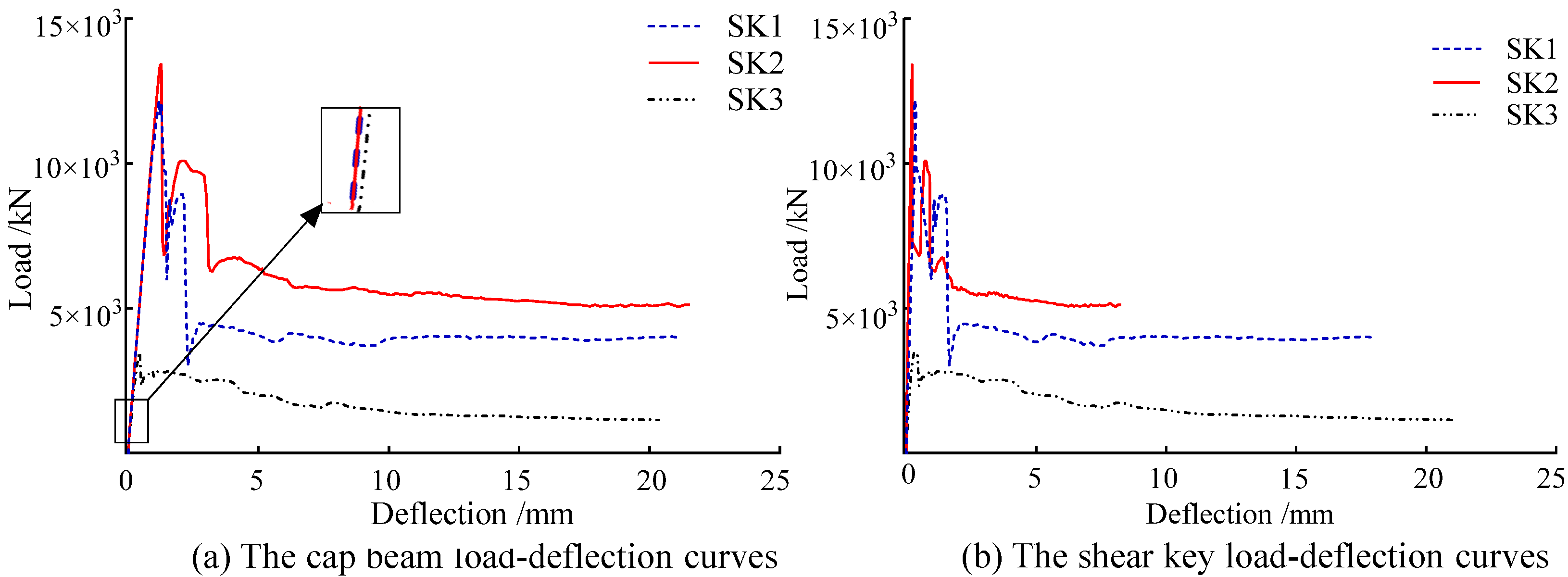
The support reactions and load–deflection curves at the loading point of the cap beam models are presented in Figure 6. During the initial loading phase, the SK1 model exhibited elastic behavior, with the bearing capacity increasing linearly with displacement. When the load reached 12,155 kN (Figure 6a), vertical cracks developed in the shear key region and propagated downward to the key root. Simultaneously, shear–compression failure occurred in the upper key zone, with diagonal cracks forming at approximately 45° from the key root toward the lower right (Figure 7a), indicating that the structure reached its ultimate bearing capacity. At this stage, although the upper shear keys had not completely fractured, the cap beam’s bearing capacity had already decreased to approximately 8850 kN. With further displacement loading, the vertical cracks continued to propagate, accompanied by the development of diagonal cracks between the loading point and the supports. Eventually, the shear key at the root failed completely (Figure 7b), forming a nearly vertical fracture surface, and the bearing capacity further degraded, stabilizing at about 4000 kN.
The load–deflection curve and failure mode of the SK2 model were similar to those of SK1. During initial loading, vertical cracks initially developed at the lower support region and propagated rapidly upward, forming approximately 45° diagonal cracks at the root of the upper-right shear key. Simultaneously, diagonal cracks appeared at the lower-left key root, with less extensive propagation, and the key root region remained intact (Figure 7c). At this stage, the model attained its ultimate bearing capacity of 13,400 kN, followed by a sharp load reduction (point (i) in Figure 6b). With continued loading, diagonal cracks emerged at the upper portion of the lower-left shear key and extended toward the support (Figure 7d), resulting in a further reduction in the bearing capacity to 6750 kN, accompanied by stiffness degradation. As displacement increased, the main cracks continued to propagate, while vertical cracks developed at the corbel root and extended into the support region. Ultimately, the shear keys failed completely, exhibiting a composite fracture surface comprising both vertical and inclined planes. The residual capacity stabilized at 5100 kN, with the load–deflection curve flattening, indicating the final failure of the cap beam.
The load–deflection behavior of the SK3 model differed significantly from that of the previous two models, mainly in its failure mode and bearing capacity development. Upon reaching the ultimate capacity (approximately 3480 kN, point (i) in Figure 6c), the root of the upper-right shear key fractured first, followed by the formation of a diagonal crack at approximately 45°, which eventually developed into a continuous main crack spanning from the upper-right loading point to the lower-left support (Figure 7c). This crack exhibited distinct diagonal tension failure characteristics, indicating a fundamental change in the shear transfer mechanism. With further displacement, the crack propagated into surrounding regions while maintaining a relatively concentrated fracture surface, indicating typical crushing of the concrete in the compression zone. In the final failure stage (Figure 7f), the residual capacity stabilized at approximately 1140 kN, and the load–deflection curve flattened, indicating that the cap beam had lost the majority of its load-carrying capacity.

4.2. Load–Deflection Curves Comparison

Figure 8a displays the load–deflection curves of support reactions versus loading-point displacements for the three cap beam models. The overall trend exhibits three distinct characteristic phases: elastic stage, crack development stage, and failure stage:
  • Under small displacement loading with intact shear keys, all models exhibited elastic behavior. The bearing capacity increased proportionally with the loading-point displacement, indicating a linear response, with identical initial stiffness observed for all models.
  • Upon entering the crack development stage, initial diagonal cracks propagated into the surrounding regions in all models. The slope of the load–deflection curves gradually decreased, indicating pronounced nonlinear behavior. During most of this stage, the tangent stiffness of SK1, SK2, and SK3 remained nearly identical. However, in the later stages, due to the sequential failure of shear keys, the reduction in bearing capacity for SK1 and SK2 occurred in distinct stages. In contrast, the shear keys of the SK3 model failed completely at an early stage, leading to a rapid reduction in bearing capacity, followed by gradual stiffness degradation as cracks continued to develop.
  • In the failure stage, the slope of the load–deflection curves approached zero. As the loading-point displacement increased, the load stabilized, and all models ultimately failed as a result of shear key fracture. In comparison with the SK3 model, both SK1 and SK2 exhibited markedly higher ultimate bearing and deformation capacities, with SK2 demonstrating the highest values for both parameters. The shear performance results of the three cap beam models are summarized in Table 3.
Figure 8b presents the comparative load–deflection curves of the shear keys for the three cap beam models, highlighting distinct mechanical responses. During early loading, the SK2 model exhibited higher initial stiffness, whereas the SK3 model exhibited the lowest initial stiffness, attributed to insufficient corbel engagement under reversed displacement loading. Regarding deformation performance, the SK2 model reached its ultimate bearing capacity at a shear key displacement of only 1.10 mm, corresponding to a 33% reduction relative to the SK1 model’s 1.65 mm displacement. The SK1 model exhibited markedly higher deformation capacity, attaining a displacement of 17.98 mm at ultimate load, which is 115% greater than that of SK2, despite a lower residual capacity. This comparative analysis indicates that, although the combined keyed–corbel epoxy joint configuration in SK2 enhances overall shear capacity and initial stiffness, it compromises the ultimate deformation capacity of the shear keys relative to the simple keyed joint in SK1. These findings offer useful insights for selecting joint configurations based on specific engineering requirements, particularly when balancing stiffness and deformation capacity.

4.3. Internal Force Analysis

Analysis of the vertical stress distribution in the three cap beam models indicates distinct stress transfer mechanisms. In the SK1 model (Figure 9a), analysis of the contact surfaces between protruding and recessed shear keys reveals that the lower surface of the recessed key carries stresses identical to those on the inclined top surface of the lower protruding keys. Stress contour analysis further indicates that load transfer in the upper shear keys follows a diagonal distribution pattern, with a pronounced deviation between the external load path and the internal stress trajectories. This diagonal compression mechanism explains the formation of 45° inclined cracks and confirms that the upper shear keys primarily transfer loads through shear resistance. In contrast, the lower shear keys transmit vertical loads diagonally to the supports in the form of vertical stresses, reflecting vertical stress transfer governed by concrete compression.
The SK2 model (Figure 9b) demonstrates distinct load distribution characteristics. Stress contour analysis indicates that the corbel structure carries the majority of vertical loads, while the remaining portion is transferred diagonally through the shear keys. The delayed crack formation in the corbel region, together with the observed crack propagation sequence described in the previous section, substantiates the role of the corbel as the primary shear-resisting component.
In contrast, the SK3 model (Figure 9c) exhibits a stress distribution complementary to that of SK2, attributable to the reversed loading direction. The upper shear keys serve as the principal load-bearing components, with negligible vertical stress observed in the corbel region. Pronounced stress concentration on the top surface of the upper shear keys indicates that vertical loads are primarily resisted by the shear keys, thereby explaining the model’s reduced shear performance.

5. Conclusions

Through finite element analysis of prefabricated segmental cap beams with the “shear key” configuration and both normal/reversed loading directions of “shear key + corbel” configurations, this study draws the following conclusions:
  • The load–deflection response of the SK2 model is broadly consistent with SK1, with failure progression characterized by vertical cracking at the lower supports, inclined crack initiation at the key roots, and eventual shear key fracture. By contrast, the SK3 model exhibits diagonal cracking at the key roots that rapidly develop into penetrating main cracks, indicative of concentrated diagonal tension failure. Comparative analysis shows that SK2 attains a higher ultimate capacity with more complex failure surfaces, whereas the altered load path in SK3 results in more brittle behavior and markedly reduced residual capacity.
  • All three models exhibit a three-phase load–displacement response comprising elastic, cracking, and failure stages. Despite identical initial stiffness, SK1 and SK2 undergo gradual capacity reduction during cracking, whereas SK3 experiences rapid stiffness loss due to premature key failure. SK1 and SK2 achieve higher ultimate capacities with sequential key fracture and superior residual deformation, while SK3’s diagonal cracking induces abrupt capacity loss and the poorest residual performance. Among them, SK2 demonstrates the most favorable shear behavior, combining enhanced ultimate capacity with greater deformation capability, thereby highlighting the decisive role of joint configuration in governing ductility and load efficiency.
  • SK2 exhibits the highest initial stiffness with minimal key displacement at ultimate load (1.10 mm), whereas SK3 presents the lowest stiffness due to insufficient corbel engagement. Despite lower residual capacity, SK1 achieves markedly greater displacement (17.98 mm), indicating superior deformation capacity. Thus, while the shear key–corbel configuration in SK2 enhances overall shear resistance, it compromises deformability, rendering the conventional SK1 design more suitable where large deformation capacity is required.
  • SK1 transfers loads via diagonal compression within shear keys, inducing 45° inclined cracks. SK2 primarily mobilizes the corbel for load transfer with supplementary key contribution, whereas SK3’s reversed loading shifts resistance to the upper keys with negligible corbel engagement, consistent with its inferior shear performance. Thus, while SK1 and SK3 rely predominantly on key mechanisms, SK2 achieves optimized load distribution through key–corbel synergy, confirming the corbel’s role as the primary shear-resisting component.
  • In future research, we will design multiple sets of experiments to provide recommendations for the optimal configuration of shear keys and corbels, dimensional suggestions, and reinforcement details for cap beam components of various spans and under different load requirements.

Author Contributions

Conceptualization, D.Y. and Y.Z.; methodology, X.L.; software, X.L.; validation, D.Y., Y.Z. and H.G.; formal analysis, Q.Z.; investigation, Q.Z.; resources, Y.Z.; data curation, H.G.; writing—original draft preparation, H.G.; writing—review and editing, Q.Z.; visualization, Q.Z.; supervision, D.Y.; project administration, D.Y.; funding acquisition, Q.Z. All authors have read and agreed to the published version of the manuscript.

Funding

This research was supported by the Jiangxi Provincial Department of Transportation Science and Technology Project, China (Grant No. 2024ZG005).

Data Availability Statement

Data are contained within the article.

Conflicts of Interest

Author Hong Gan is employed by Jiangxi Gan Yue Expressway Co., Ltd. Author Qing Zhang is employed by Jiangxi Gan Yue Expressway Co., Ltd. and Jiangxi Changtong Expressway Co., Ltd. The remaining authors declare that the research was conducted in the absence of any commercial or financial relationships that could be construed as potential conflicts of interest.

References

  1. Khan, M.A. Accelerated Bridge Construction: Best Practices and Techniques; Butterworth-Heinemann: Oxford, UK, 2015; ISBN -13 978-0124072251. [Google Scholar]
  2. Xiang, Y.Q.; Zhu, S.; Zhao, Y. Research and development on accelerated bridge construction technology. China J. Highw. Transp. 2018, 31, 1–27. [Google Scholar] [CrossRef]
  3. Huo, L.F.; Fang, C.P.; Yao, X.F.; Liu, H.; Liu, S. Research on bending resistance of prefabricated and assembled cap beams with large cantilever prestressed segments. Concrete 2024, 10, 137–142. [Google Scholar] [CrossRef]
  4. Ye, M.; Li, L.; Hu, F.; Shao, X.; Tang, J. Flexural Behavior of a Fully Prefabricated Lightweight UHPC Bent Cap. J. Bridge Eng. 2020, 25, 04020085. [Google Scholar] [CrossRef]
  5. Ye, M.; Li, L.; Hu, F.; Wang, L.; Shao, X. UHPC-Based Precast Large-Cantilevered Thin-Walled Bent Caps: Design and Experiments. Eng. Struct. 2022, 272, 114909. [Google Scholar] [CrossRef]
  6. Li, C.; Zhuo, W.; Lin, K.; Sun, Y.; Chen, M. Experimental Study on Flexural Behavior of Segmental Precast Large-Cantilevered Prestressed Concrete Cap Beam. Structures 2023, 57, 105166. [Google Scholar] [CrossRef]
  7. Chung, C.H.; Lee, J.H.; Kwon, S.H. Proposal of a New Partially Precast Pier Cap System and Experimental Verification of Its Structural Performance. KSCE J. Civ. Eng. 2018, 22, 2362–2370. [Google Scholar] [CrossRef]
  8. Ge, J.P.; Mei, D.L.; Yan, X.F.; Wang, Z. Comparison and analysis of construction methods for precast pier caps. J. Technol. 2018, 18, 56–62. [Google Scholar] [CrossRef]
  9. Le, T.D.; Pham, T.M.; Hao, H.; Hao, Y. Flexural Behaviour of Precast Segmental Concrete Beams Internally Prestressed with Unbonded CFRP Tendons under Four-Point Loading. Eng. Struct. 2018, 168, 371–383. [Google Scholar] [CrossRef]
  10. Le, T.D.; Pham, T.M.; Hao, H.; Yuan, C. Performance of Precast Segmental Concrete Beams Posttensioned with Carbon Fiber-Reinforced Polymer (CFRP) Tendons. Compos. Struct. 2019, 208, 56–69. [Google Scholar] [CrossRef]
  11. Jiang, H.B.; Li, H.Y.; Xiao, J.; Chen, Y.; Fang, Z. Shear behavior of precast concrete segmental simply supported beam with external strands and dry joints. China J. Highw. Transp. 2018, 31, 188–195. [Google Scholar] [CrossRef]
  12. Li, G.; Wang, J.; Shen, Y.; Li, L.; Chen, M. Experimental Study on the Combined Shear and Bending Behaviour of Corbel Joints in Precast Concrete Segmental Inverted-T Caps. Structures 2020, 28, 2367–2378. [Google Scholar] [CrossRef]
  13. Shen, C.; Zhang, D.; Liu, W.; Fu, K.; Wang, F.; Wu, X.; Wang, D. Shear Capacity Model of Prefabricated Shear-Keyed Tooth Joints Under Confining Stress. Buildings 2024, 14, 4042. [Google Scholar] [CrossRef]
  14. Le, T.D.; Pham, T.M.; Hao, H.; Li, H. Behavior of Precast Segmental Concrete Beams Prestressed with External Steel and CFRP Tendons. J. Compos. Constr. 2020, 24, 04020053. [Google Scholar] [CrossRef]
  15. Li, C.C.; Zhuo, W.D.; Sun, Z.X.; Xiao, Z.; Chen, G.; Huang, X. Static behavior of segmental precast assembled cap beam with corbel joints. J. Harbin Eng. Univ. 2023, 44, 1328–1335. [Google Scholar] [CrossRef]
  16. Yan, X.F.; Ge, J.P.; Wang, Z.Q.; Gao, F.; Han, S.; Zhang, C.; Zhang, T. Research on flexural performance of prefabricated segmental prestressed concrete bent caps with large cantilevers. China Munic. Eng. 2019, 4, 72–76+118–119. [Google Scholar] [CrossRef]
  17. Huang, B.C.; Huang, Y.C.; Zhang, S. Research on the effect of shear keys on the mechanical properties of precast segmental cap beams. J. China Foreign Highw. 2020, 44, 192–197. [Google Scholar] [CrossRef]
  18. Huang, W.X.; Tang, W.H.; Xiao, T.L.; Zhe, H.; Huang, Z. Experimental and finite element analysis on shear performance of new keyed epoxy joint. J. Yangtze Univ. 2025, 1–10. [Google Scholar] [CrossRef]
  19. Chen, C.; He, W.Z.; Gao, Y.X. Optimal Design and Performance Analyses of RPC Bracket Joint. Bull. Sci. Technol. 2017, 33, 216–219. [Google Scholar] [CrossRef]
  20. Li, C.C.; Qin, Z.Q.; Chen, J.D.; Zhuo, W.D. Tests and Parametric Analysis of Shear Bearing Capacity of Epoxy Joints in Concrete Cap Beam. J. Tianjin Univ. 2025, 58, 368–378. [Google Scholar] [CrossRef]
  21. Wu, C.X.; Gao, P.Y.; Zhang, G.M.; Zhang, C. Structural behavior analysis of precast concrete cap beams. J. China Foreign Highw. 2023, 43, 208–217. [Google Scholar] [CrossRef]
  22. Liang, X.; Sritharan, S. Use of Unstressed Strands for Connections of Precast Concrete Members. PCI J. 2021, 66, 49–66. [Google Scholar] [CrossRef]
  23. Lu, W.; Li, F.; Zhu, L.; Wen, C.; Peng, W. Experimental Study on the Shear Behavior of Precast Concrete Segmental Simply Supported Beam with Internal Tendons and Glue Joints. Case Stud. Constr. Mater. 2022, 17, e01545. [Google Scholar] [CrossRef]
  24. Chen, P.; Cao, P.; Shi, F.; Chen, L.; Pei, X.; Tan, Z. Bolted Connections in Prefabricated Cantilevered Cap Beam-Column Structures: A Comprehensive Experimental and Numerical Study. Eng. Struct. 2024, 310, 118124. [Google Scholar] [CrossRef]
  25. Lee, J.; Fenves, G.L. Plastic-Damage Model for Cyclic Loading of Concrete Structures. J. Eng. Mech. 1998, 124, 892–900. [Google Scholar] [CrossRef]
  26. Ludwig, W. Abaqus CFD User’s Guide; Version 6.13.1; Dassault Systèmes Simulia Corp: Waltham, MA, USA, 2013; pp. 691–693. [Google Scholar]
  27. Jiang, H.; Chen, L.; Ma, Z.J.; Feng, W. Shear Behavior of Dry Joints with Castellated Keys in Precast Concrete Segmental Bridges. J. Bridge Eng. 2015, 20. [Google Scholar] [CrossRef]
  28. Liu, T.; Wang, Z.; Guo, J.; Wang, J. Shear Strength of Dry Joints in Precast UHPC Segmental Bridges: Experimental and Theoretical Research. J. Bridge Eng. 2019, 24, 1–18. [Google Scholar] [CrossRef]
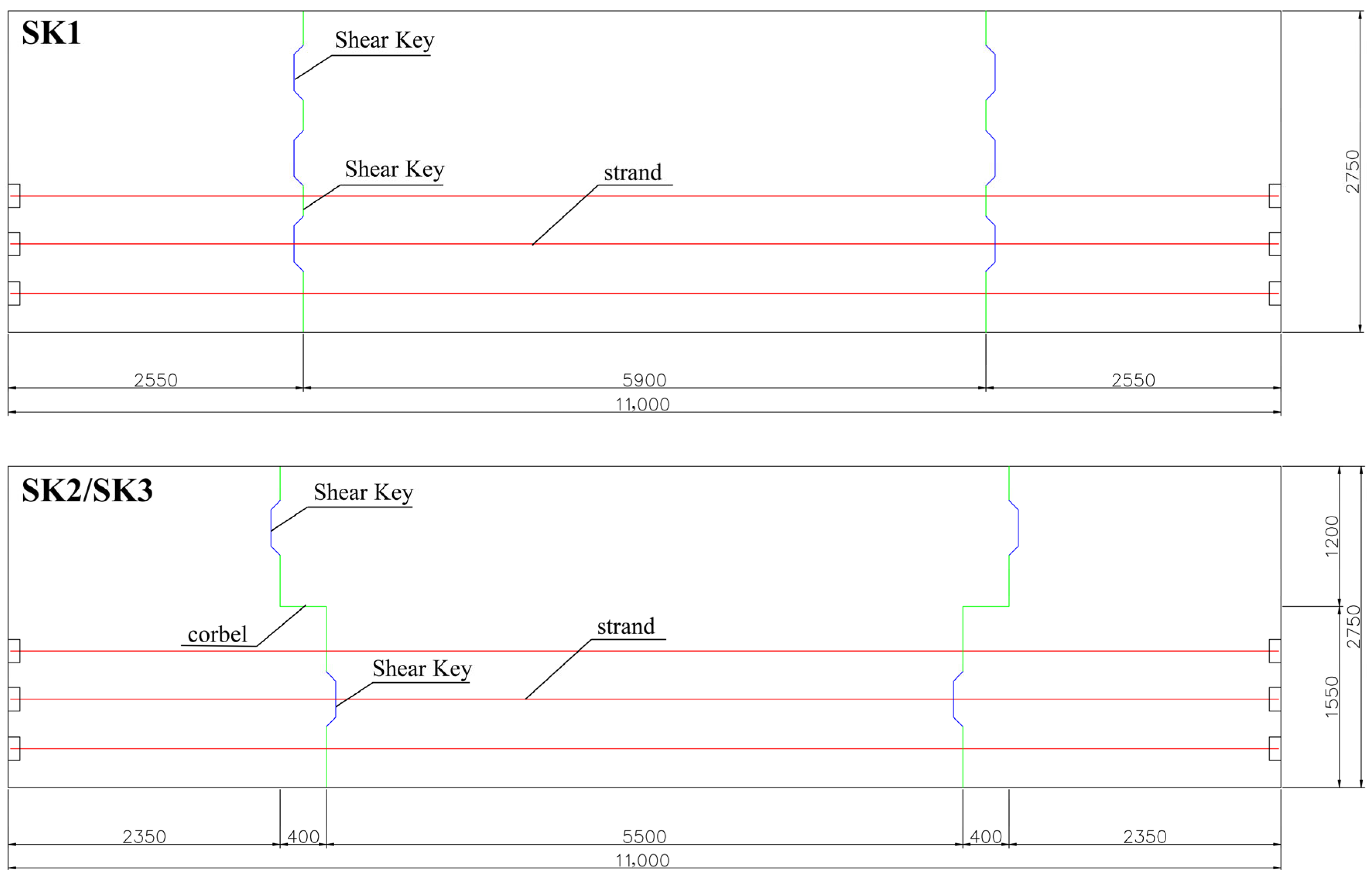
Figure 1. The section of cup beam and prestressing strands (mm).
Buildings 15 04286 g001
Figure 2. The section of the adhesive joint and beam reinforcement (mm).
Buildings 15 04286 g002
Figure 3. The SK2 cap beam finite element model.
Buildings 15 04286 g003
Figure 4. Displacement loading scheme.
Buildings 15 04286 g004
Figure 5. Finite element modeling process of the SK2 cap beam [26].
Buildings 15 04286 g005
Figure 6. Cap beam load–deflection curve.
Buildings 15 04286 g006
Figure 7. Failure mode distribution.
Buildings 15 04286 g007
Figure 8. Load–deflection curves comparison.
Buildings 15 04286 g008
Figure 9. Shear key vertical stress.
Buildings 15 04286 g009
Table 1. Parameters of the concrete plastic damage model [24,25].
Dilation
Angle
ψ
Eccentricity
e
Ultimate Compressive
Strength Ratio
Constant Stress Ratio
Kc
Viscosity
Parameter
ν
300.11.160.6670.0005
Compressive behaviorTensile behavior
Damaged factorCracking strainDamaged factorInelastic strain
0.000000.000000.000000.00000
0.166980.000430.071460.00001
0.204650.000600.093220.00002
0.24221 0.000780.128220.00003
0.278890.000970.275440.00007
0.37235 0.001480.412860.00012
0.47408 0.002060.512880.00016
0.55951 0.002620.585060.00019
0.62612 0.003140.638640.00022
0.67751 0.003640.777930.00037
0.81381 0.005880.837350.00050
0.87048 0.007980.870510.00063
0.90095 0.010050.906720.00089
0.93276 0.01415 0.926320.00115
0.949140.018220.943390.00153
0.962760.024330.956270.00204
0.972570.032460.964110.00256
Table 2. Material parameters of reinforcement and prestressing strands.
TypeYield Strength
/MPa
Ultimate Strength
/MPa
Elastic Modulus
/GPa
Strands ϕS15601860195
HRB400Buildings 15 04286 i00112400540200
HRB400Buildings 15 04286 i00216400540200
HRB400Buildings 15 04286 i00328400540200
Table 3. Summary of shear performance results for three cap beam models.
Cap BeamsUltimate Bearing
Capacity
/kN
Residual Bearing
Capacity
/kN
Ultimate
Deflection /mm
Shear key Deflection at
Ultimate Load
/mm
Shear Key Ultimate Deflection
/mm
SK112,15540002.291.6517.98
SK213,40051003.241.108.38
SK3348011400.520.5121.19
Disclaimer/Publisher’s Note: The statements, opinions and data contained in all publications are solely those of the individual author(s) and contributor(s) and not of MDPI and/or the editor(s). MDPI and/or the editor(s) disclaim responsibility for any injury to people or property resulting from any ideas, methods, instructions or products referred to in the content.