Abstract
Cold-formed thin-walled steel (CFS) members were widely used in steel structures but faced challenges in meeting bearing capacity and assembly efficiency requirements as single-limb members. To overcome the above limitations, a promising fold-fastened multi-cellular steel panel (FMSP) was proposed. The FMSP eliminated the need for discrete self-drilling screws, instead utilizing a continuous mechanical fold-fastened connection, which enhanced structural integrity and assembly efficiency. This approach also provided greater flexibility to meet the design requirements of complex structural configurations. This study investigated the flexural behaviors of panels—a key mechanical property governing their structural behavior. A bearing capacity test was conducted on five FMSP specimens, focusing on the failure modes, bending moment–deflection curves, deflection distributions under representative loading levels, and flexural bearing capacities of the specimens. Refined finite element models (FEMs) of the specimens were established, and the stress and deformation distributions were further studied. The comparison results showed that the numerical results were in good agreement with the experimental results. Finally, the parametric analysis was carried out, and the influence of key parameters on the flexural behavior was revealed. Analysis results demonstrated that doubling the steel plate thickness increased the flexural capacity by 207%, while a twofold increase in panel thickness resulted in a 123% improvement. In contrast, increasing the steel strength from 235 MPa to 460 MPa yielded only a 61% enhancement. This research laid a solid foundation for promoting the application and investigation of FMSPs, thus achieving high industrialization and meeting the requirements of complex structural design.
1. Introduction
This section outlines the research background and motivation for investigating the flexural behavior of the fold-fastened multi-cellular steel panel (FMSP). It begins by reviewing the applications and limitations of conventional cold-formed steel (CFS) members, and then introduces the novel FMSP system as a solution. Finally, it clearly states the objectives and scope of the present study.
Compared to concrete structures and steel frames, cold-formed thin-walled steel (CFS) exhibited favorable attributes such as economic viability, low self-weight, simplified construction, and notable seismic resistance [1,2,3,4]. These advantages made CFS an ideal choice for cost-effective construction and sustainable development, particularly in multi-story residential building construction and retrofitting, where its economic efficiency and factory production characteristics could be fully leveraged. Consequently, CFS attracted significant attention from numerous engineers and researchers. Common single-limb CFS members included C-, U-, box-, angle-, and circular-sections. However, in practical engineering applications, single-limb members often proved inadequate to meet structural bearing capacity requirements. To address this limitation, C-, U-, and box-sectional members were typically used as basic components and connected with self-drilling screws to form built-up members, whose common cross-sectional configurations are illustrated in Figure 1.
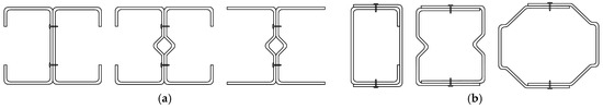
Figure 1.
Common cross-section forms of CFS members: (a) Build-up I-sectional member; (b) Build-up box-sectional member.
In recent years, extensive research has been conducted to explore the member performance of cold-formed thin-walled steel (CFS) [5,6]. For single-limb members, foundational contributions were made [7,8,9,10,11,12,13]. A series of experimental and numerical analyses focusing on global, local, distortional, and interactive buckling of C-section beams were carried out [14,15,16,17]. Wang et al. [18] and Zhang et al. [19] numerically and experimentally investigated the flexural behavior of channel-section beams, while Li et al. [20] conducted a series of four-point bending tests and extensive numerical simulations to study the flexural behavior of box-section beams.
For built-up I-section members, Zhou et al. [21] and Yao et al. [22] carried out comprehensive experimental and numerical analyses, examining the ultimate bearing capacity and failure modes under bending moments. They proposed a flexural capacity formula based on the effective width method (EWM) and verified its accuracy and applicability. Phan et al. [23] revealed the influence of self-drilling screw connections, welding, and bolted connections on the bending stiffness of such members. Through experimental research, Chen et al. [24] found that built-up I-section members with stiffening holes exhibited higher flexural capacity than those without openings. Roy et al. [25,26] explored the effect of spacing between individual limbs on the flexural capacity of built-up I-section members. Phan et al. [27,28] further conducted tests and numerical analyses on the flexural capacity of three-limb and four-limb complex built-up I-section members, finding that mono-symmetric sections were more susceptible to flexural-torsional buckling compared to doubly symmetric sections. Li and Young [29] investigated built-up I-section and box-section members subjected to uniform and non-uniform minor axis bending, revealing their flexural behavior under moment gradients. They developed a predictive formula through numerical simulation and the direct strength method (DSM). Wang and Young [30,31,32] studied the flexural capacity and failure modes of various built-up I-section and box-section beams under three- and four-point bending, leading to calibration of the DSM. Their subsequent work experimentally examined members with web openings, further refining the DSM to account for hole effects.
For built-up box-section members, Serrette [33] experimentally studied the flexural behavior of built-up box-section members under eccentric loading, observing interactive torsional-flexural buckling and noting reduced capacity due to load eccentricity. Xu et al. [34] analyzed the flexural capacity of such members under eccentric compression, examining influences of material strength, flange width-to-thickness ratio, and section height-to-width ratio. Li et al. [35] conducted strong- and weak-axis bending tests, proposing a simplified flexural capacity formula. Selvaraj and Madhavan [36] investigated the effects of member length and spot weld spacing on built-up box-section capacity through flexural tests, evaluating existing design methods and proposing improved formulas. Anbarasu and Karthik [37,38] numerically analyzed flexural behavior using ABAQUS, modifying existing DSM-based code provisions. Karthik et al. [39] performed three- and four-point bending tests on built-up box-section members, characterizing flexural behavior and evaluating relevant design codes.
Based on the preceding summary, it is evident that extensive research has been conducted on both single-limb and built-up CFS members. However, several limitations associated with self-drilling screw connections can be identified. First, these connections require substantial on-site manual labor, significantly prolonging construction timelines and hindering fully assembled, industrialized production. Second, the discrete distribution of screws creates discontinuities at contact surfaces, compromising structural integrity. Third, the mechanical influence of screws must be carefully accounted for, increasing the complexity of structural design. Finally, built-up members are predominantly applied as column elements, with limited flexibility in sectional dimensions and cell configuration, rendering them insufficient for meeting the demands of complex engineering applications.
A novel CFS built-up closed section member, namely the fold-fastened multi-cellular steel panel (FMSP), was introduced. As shown in Figure 2, the FMSP was composed of edge and basic members, which were connected by fold-fastened regions formed by mechanical embedding of hook-shaped and groove-shaped regions. The proposed FMSP directly addressed these limitations [40,41,42]: (1) The fold-fastened connection was achieved through an automated mechanical fold-fastened process, which drastically reduced on-site manual labor and enabled a higher degree of prefabrication and industrialized production. (2) The continuous, interlocking hook-and-groove connection created a unified force transfer path, mitigating the stress concentrations caused by discrete screws and thereby enhancing the overall structural integrity and continuity. (3) By eliminating the need to model individual screw connections and their localized effects, the FMSP simplified the structural design process. (4) The modular nature of the FMSP allowed it to be flexibly configured as beams, columns, walls, and floors by varying the cell number, as demonstrated in the experimental program (Table 1), thus providing a versatile solution for complex engineering projects beyond the scope of traditional column members. FMSP has been applied in prefabricated buildings, as shown in Figure 3.
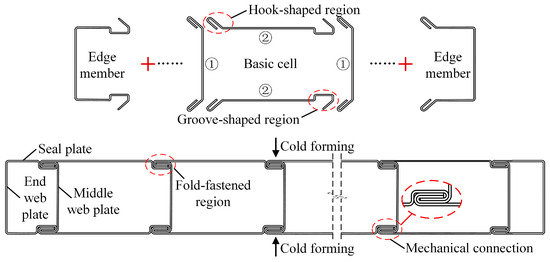
Figure 2.
Composition of FMSP.
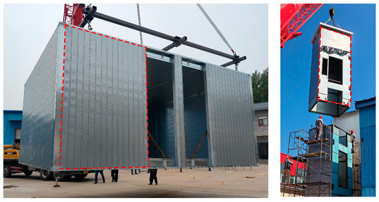
Figure 3.
FMSPs in engineering applications.
The pursuit of such innovative connection techniques was aligned with the broader research trends in the CFS community, which focused on enhancing not only the structural performance but also the sustainability and digital design capabilities of modern construction systems. Recent studies have emphasized integrated structural and energy performance [43], high-fidelity numerical modeling of flexural behavior [44], and data-driven strength prediction [45]. The present study complemented these directions by: (1) establishing and validating a refined finite element model with high accuracy for this novel system; and (2) generating a reliable experimental dataset that can support the development of future data-driven models.
When FMSPs were used as wall or floor members, they would inevitably be subjected to out-of-plane bending moments. Therefore, to expand the application range of the FMSP, it was extremely important to study its flexural bearing capacity. In this paper, the flexural bearing capacity of the FMSP was studied by four-point bending tests and simulations. The main contributions of this study were summarized as follows: (1) Experimental observation revealed a characteristic failure mode involving local buckling at the mid-span upper flange, accompanied by local compression at loading points. It was further discovered that overly deep indented regions could lead to unfavorable interconnected local buckling, leading to the design recommendation for a staggered layout. (2) A refined FEM was established and validated against test results, demonstrating excellent accuracy in replicating failure modes and bearing capacity, with computational errors primarily within ±5%. (3) A systematic parametric study quantified the influence of critical design parameters. The results showed that the ultimate flexural capacity exhibited a near-linear increase with the panel thickness, the steel plate thickness and cell number, whereas widening the panel or the fold-fastened region yielded diminishing returns. (4) Based on the findings, practical design advice was provided, including the avoidance of excessively wide fold-fastened regions and the prioritized use of increased panel thickness and plate thickness to efficiently improve flexural performance.
2. Experimental Program
This section provides a comprehensive description of the experimental methodology employed in this study. It details the specimen design and preparation, test setup and instrumentation, and the material properties obtained from tensile coupon tests.
2.1. Experimental Design
2.1.1. Specimen Preparation
The flexural behavior of FMSPs was studied experimentally. All specimens were obtained from the actual elevator shaft structure, and the corresponding material was steel S350 [46]. In this paper, three groups of specimens were designed, two of which included repeated tests, resulting in a total of five FMSPs. A closed section was formed by sealing the free edges on both sides of the specimen using self-drilling screws and U-sectional channel steel.
To prevent local compression failure at the end of the specimen and the loading location, wooden blocks were added at the corresponding positions inside the specimens, and the U-sectional channel steel was connected by self-drilling screws at both ends of the specimen. Wood blocks were inserted into the panel interior. After installation, tight contact with the steel faceplates was verified through acoustic testing (sound upon tapping) and visual inspection to ensure effective load transfer. Figure 4 shows the on-site installation of the wood blocks.
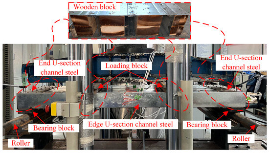
Figure 4.
On-site assembly specimen.
Since the wooden blocks were primarily in compression during testing, and the compressive stress they experienced was significantly lower owing to a larger bearing area, they exhibited negligible strain compared to the panel itself under actual test conditions. Therefore, these wood blocks could be considered rigid relative to the panel. It should be noted that the primary function of the wood blocks was to distribute loads to the panel and prevent local buckling, rather than to significantly participate in carrying bending stresses. To simulate the simply supported boundary conditions, the bearing blocks were welded under the U-sectional channel steel at the end, and the rollers were placed. The on-site assembly specimen is illustrated in Figure 4.
The parameters considered in the specimen design were the cell number nw, the panel thickness dw, and the steel plate thickness tw. The detailed dimensions of the specimens are shown in Figure 5 and Table 1. To clearly reflect these variables, the specimens were named using the format OFW-X-Y-Z, where X represents the number of cells (nw), Y represents the panel thickness in mm (dw), and Z represents the steel plate thickness in mm (tw × 10) for brevity. For example, OFW-2-100-7 denotes a specimen with 2 cells, a 100 mm panel thickness, and a 0.7 mm steel plate thickness. It is noted that only one specimen was tested for the OFW-3-200-7 configuration due to material supply constraints during fabrication; however, the finite element validation presented in Section 4.3 provides strong corroborating evidence for its mechanical behavior.

Table 1.
Detailed dimensions of specimens.
Table 1.
Detailed dimensions of specimens.
| Specimen | bw (mm) | dw (mm) | hw (mm) | nw | s | Dimensions of the Cell | Steel | Number of Replicates | ||
|---|---|---|---|---|---|---|---|---|---|---|
| b1 (mm) | dw (mm) | tw (mm) | ||||||||
| OFW-2-100-7 | 450 | 100 | 1500 | 2 | 140 | 150 | 100 | 0.7 | S350 | 2 |
| OFW-3-100-7 | 600 | 100 | 1500 | 3 | 140 | 150 | 100 | 0.7 | S350 | 2 |
| OFW-3-200-10 | 600 | 200 | 1500 | 3 | 140 | 150 | 200 | 1.0 | S350 | 1 |

Figure 5.
Schematic diagram of specimens: (a) Cross-sectional view; (b) Three-dimensional view.
Considering processing errors and to provide accurate geometric dimensions for FEMs, the cross-sectional dimensions of all specimens were meticulously measured before testing. The measurements were conducted using a steel ruler with a gauge resolution of 0.1 mm. The specific measurement protocol was as follows. For the panel height (hw): The height was measured along both the left and right edges of the panel, and the average of these two values was taken as the final height. For other cross-sectional dimensions: These dimensions were measured at three cross-sections located at 1/4, 1/2, and 3/4 of the specimen’s height. The average value from these three sections was calculated and used as the final dimension. The measurement results are presented in Table 2. With reference to GB 50205-2020 [47], which specifies a manufacturing tolerance of ±3 mm, the overall dimensions of the fabricated specimens were deemed to comply with the requirements.
Table 2.
Measured dimensions of specimens.
2.1.2. Test Setup, Instrumentation, and Loading Protocol
The four-point bending test was used to evaluate the flexural behavior of the specimens. The test was completed on a 1000 kN compression testing machine. The test setup and on-site photos are shown in Figure 6. Six linear variable displacement transducers (LVDTs) were mounted to measure the deflections at the midspan, loading point, and support point, as shown in Figure 7.
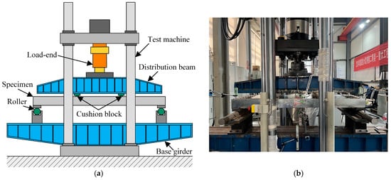
Figure 6.
Sectional dimensions of specimens: (a) Diagram of test setup; (b) On-site test setup.
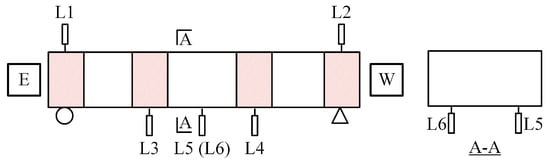
Figure 7.
Arrangement of measuring points.
Referring to existing research, two-stage loading was adopted in the test [48,49]. Initially, force control loading was utilized until the load reached 1/3 of the estimated bearing capacity, with a loading rate of 2 kN/min. Subsequently, the loading mode was changed to the displacement control, maintaining a loading rate of 0.5 mm/min, until the specimen was damaged or the loading beam was about to touch the specimen.
2.2. Material Properties
Considering the error between the measured and design strengths, the tensile test was carried out before the bearing capacity test. The tensile test coupon was designed according to GB/T 228.1-2021 [50], as shown in Figure 8a. The tests were conducted using an INSTRON 8802 universal testing machine (Instron-Division of ITW Ltd., Egham, UK). To accurately capture the material’s yield behavior, a 50 mm gauge-length extensometer was attached to the middle portion of the coupon to measure the tensile strain. The loading was applied under displacement control at a constant rate of 1.0 mm/min until the coupon fractured. The loading process is presented in Figure 8b. According to the thickness, the steel S350 was divided into #A and #B, and three tensile coupons were taken in the outer and web plates, respectively. For steel Q355, it was divided into #C, #D, and #E according to the thickness, and three tensile coupons were taken for each group. The specific results are shown in Table 3 and Figure 8c. The yield strength fy, ultimate strength fu, and elastic modulus E of each coupon in the same group were relatively close.
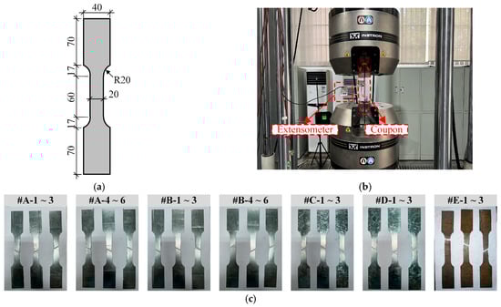
Figure 8.
Details of tensile coupon tests: (a) Size of the coupon (Unit: mm); (b) Tensile test process; (c) Coupons after tests.
Table 3.
Tensile test result.
3. Test Results and Discussion
This section presents and discusses the key findings from the four-point bending tests. It begins with a description of the general failure modes, followed by a detailed analysis of the bending moment-deflection responses and deflection distributions.
3.1. General Observation and Failure Modes
In the bearing capacity test of FMSPs, taking OFW-2-100-7 as an example, the test phenomena were described to illustrate the failure process in detail. At the force control loading stage, the specimen remained in an elastic state and no buckling occurred. At the displacement control loading stage, the free edge of the cell at the midspan started to bulge (corresponding load F = 12.1 kN), as shown in Figure 9a. Local compression deformation appeared in the loading location (corresponding load F = 15.8 kN). The lower free edge of the loading location experienced significant deformation due to the compression of the wooden block, resulting in an overestimation of the corresponding LVDT reading, as shown in Figure 9b. The upper free edge of the cell at midspan also began to bulge (corresponding load F = 19.8 kN). Distinct local buckling occurred, which was caused by the development of bulging in the upper free edge (corresponding load F = 26.2 kN), as shown in Figure 9c. Subsequently, the load reached the capacity (corresponding load F = 29.8 kN), and significant local buckling occurred in the upper flange at the midspan, but the indented regions did not separate or exhibit interconnected local buckling, as shown in Figure 9d. As the displacement further increased, the specimen gradually lost its bearing capacity, and the indented region began to separate. The ultimate failure mode involved local buckling of the upper flange and the web at the midspan, accompanied by some local compression deformation of the loading location, as shown in Figure 9e.
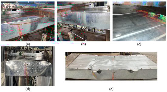
Figure 9.
Test phenomena of OFW-2-100-7: (a) Bulge of the free edge of edge cell; (b) Local compression deformation at loading point; (c) Local buckling of mid-span upper flange; (d) Mid-span deformation in limit state; (e) Overall failure of the specimen.
The typical failure modes of the specimens are presented in Figure 10. OFW-2-100-7 exhibited local buckling of the upper flange and the web at the midspan, accompanied by slight local compression buckling of the loading location. OFW-3-100-7 displayed interconnected local buckling along the indented region of the upper flange. OFW-3-200-10 demonstrated local compression deformation of the loading location. It was noted that in the design, interconnected local buckling failure due to too deep indented regions should be avoided, such as OFW-3-100-7. Therefore, it was recommended to arrange the indented region in a staggered layout.
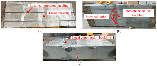
Figure 10.
Typical failure modes: (a) OFW-2-100-7; (b) OFW-3-100-7; (c) OFW-3-200-10.
3.2. Test Results
3.2.1. Bending Moment–Deflection Curves
As shown in Figure 11, it could be observed that the curves exhibited similar trends, divided into four stages: linear stage, nonlinear stage, peak load, and descent stage. At the initial loading stage, the bending moment–deflection curves showed a nearly linear relationship, with minor variations in stiffness among the specimens. When the load reached approximately 40% of the bearing capacity, the curves displayed nonlinear behavior until reaching the peak load. Subsequently, the curves exhibited a nonlinear descent with increasing deflection, ultimately leading to specimen failure. Near the peak load, the specimen exhibited significant deflection increase with small load changes. It was noted that before reaching the peak load, the curve of OFW-3-200-10 exhibited fluctuations due to the loosening of the end self-drilling screws and an increase in the gap between the end channel steel and the panel.
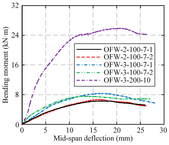
Figure 11.
Bending moment–deflection curves of specimens.
The flexural bearing capacities of OFW-2-100-7-1 and OFW-2-100-7-2 were close, while the flexural bearing capacities of OFW-3-100-7-1 and OFW-3-100-7-2 had a certain difference. This variability is quantified in Table 4, showing a difference of approximately 5.23% in ultimate moment and a more pronounced 20.4% difference in initial stiffness between the two OFW-3-100-7 specimens. The notably higher initial stiffness but lower ultimate capacity of OFW-3-100-7-2 suggests the presence of an initial unintended restraint, possibly due to minor misalignment or a tighter fit during assembly. This initial constraint could have led to the higher measured stiffness in the early loading stage. However, this same imperfection likely induced localized stress concentrations, ultimately precipitating failure at a lower ultimate load compared to OFW-3-100-7-1. Despite this variability, the average values of the OFW-3-100-7 group are considered representative for comparative analysis, and the overall trends remain clear and consistent.
Table 4.
Test results of specimens.
A quantitative comparison reveals the distinct influence of key geometric parameters. Increasing the cell number from 2 (OFW-2-100-7, Mu,avg = 6.50 kN·m) to 3 (OFW-3-100-7, Mu,avg = 8.02 kN·m) enhanced the average flexural capacity by 23.4%, while the initial stiffness rose markedly from 0.67 kN·m/mm to 1.08 kN·m/mm, representing a 61.2% improvement. A more pronounced effect was observed when both the panel thickness and steel plate thickness were increased simultaneously in specimen OFW-3-200-10 (dw = 200 mm, tw = 1.0 mm) relative to OFW-3-100-7 (dw = 100 mm, tw = 0.7 mm), resulting in a remarkable 223.2% increase in flexural capacity (25.92 kN·m vs. 8.02 kN·m) and a 203.7% increase in initial stiffness (3.28 kN·m/mm vs. 1.08 kN·m/mm), thereby highlighting the exceptional effectiveness of optimizing these two parameters in tandem.
To evaluate the ductility performance of FMSPs, the ductility coefficient μ was calculated for each specimen using Equation (1), where Δd represents the displacement on the descending branch of the curve corresponding to 85% of the peak load Nu (i.e., Nd), and Δy denotes the displacement associated with the yield load Ny, determined according to the method illustrated in Figure 12. As summarized in Table 4, the calculated ductility coefficients exceeded 1.86, indicating that the FMSP specimens exhibit satisfactory ductility.
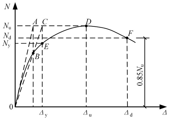
Figure 12.
Geometric graphic method of ductility coefficient.
3.2.2. Deflection Distributions Under Representative Loading Levels
The deflection distribution of each specimen along the span at different load stages is shown in Figure 13. At the early stage of loading, the deflection was relatively small. When the load reached approximately 40% of bearing capacity, the deflection increased rapidly until the peak load.
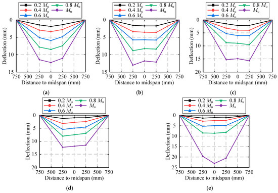
Figure 13.
Deflection distributions under representative loading levels: (a) OFW-2-100-7-1; (b) OFW-2-100-7-2; (c) OFW-3-100-7-1; (d) OFW-3-100-7-2; (e) OFW-3-200-10.
Regarding deformation capacity, the mid-span deflection at peak load for OFW-3-200-10 was 20.71 mm, which is approximately 27% greater than the average of OFW-2-100-7 (16.36 mm) and 36% greater than the average of OFW-3-100-7 (15.47 mm), indicating a different failure progression. Nevertheless, all specimens demonstrated excellent deformation capacity, with the deflection from 0.4 Mu to Mu increasing by over 300%. Additionally, the deflection change was symmetrically distributed.
4. Finite Element Modeling
This section elaborates on the development, validation, and application of the refined finite element model. It details the model setup—including element selection, mesh sensitivity, boundary conditions, and material constitutive law—followed by a rigorous validation against experimental results. The validated model is then employed for an extensive parametric analysis to investigate key influencing factors.
4.1. Development of FEM
4.1.1. Element and Mesh
The refined FEMs were established by using ABAQUS 6.14. The geometric model was mainly composed of the FMSP, the end channel steel, the loading block, the bearing block, and the inner wooden block, as shown in Figure 14. Considering that the thickness of the steel plate was much smaller than the overall structural dimensions, and the stress in the thickness direction could be ignored, the S4R shell element was selected, which was defined with five integration points through the thickness and capable of accommodating shear deformation along that direction [51,52,53,54]. To better obtain the stress and deformation of the fold-fastened region, the mesh refinement was carried out, and the local mesh size was taken as 5 mm (along the x-axis), as shown in Figure 15.
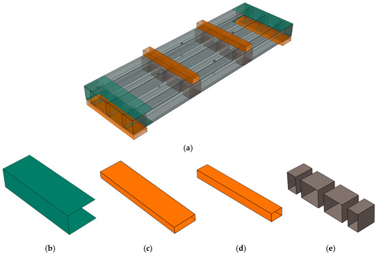
Figure 14.
Composition of FEM: (a) Assembly model; (b) End channel steel; (c) Bearing block; (d) Loading block; (e) Inner block.
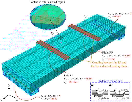
Figure 15.
Details of FEM.
Taking OFW-2-100-7-2 as an example, four different overall mesh sizes of 7.5, 10, 12.5, and 15 mm were selected. The corresponding bending moment–deflection curves are presented in Figure 16a. It could be drawn that the initial stiffness and variation trend of each curve were consistent. When the overall mesh size was greater than 10 mm, the bearing capacity was significantly affected. When the overall mesh size was not more than 10 mm, the bearing capacity was rarely affected by the change in mesh size, and the error between the numerical and experimental results of OFW-2-100-7-2 was within ±5%, as shown in Figure 16b. Therefore, it was considered that the numerical results were convergent with a mesh size of not more than 10 mm. To balance the computational efficiency and accuracy, 10 mm was reasonably selected as the overall mesh size.
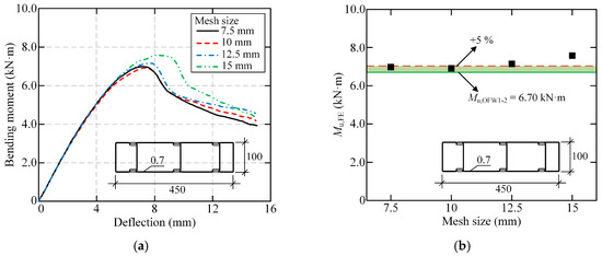
Figure 16.
Sensitivity analysis of mesh size: (a) Bending moment-deflection curves; (b) Comparison of bearing capacity.
4.1.2. Interactive Property
For the accuracy of numerical analysis, surface-to-surface contact was used to simulate the interaction between plates. The normal direction with finite slip was defined as hard contact. The tangential direction was defined as the coulomb friction model, and the penalty function method was adopted to ensure the coordination of the contact surface, and the friction coefficient was 0.2 [55]. Due to the welding of the end channel steel and the bearing block in the test, in which the tie constraint was set. In addition, mesh-independent fasteners were utilized to simulate the additional self-drilling screws during specimen processing [56,57].
4.1.3. Boundary Condition and Load System
To ensure consistency between the boundary conditions of the FEMs and tests, the translational degree of freedom (DOF) along the z-axis (uz) and the rotational DOF around the x-axis (urx) of the lower surface centerline of the left bearing block were released, while all other DOFs were constrained. Similarly, the rotational DOF around the x-axis (urx) of the lower surface centerline of the right bearing block was released, while all other DOFs were constrained. Simply supported boundaries could be achieved by the above methods. Reference points (RPs) were established at the center points of the upper surfaces of the loading blocks, and they were coupled with their corresponding upper surfaces. The loading process was simulated by applying displacement loads in the y-direction to the RPs. The specific boundary condition is detailed in Figure 15.
4.1.4. Initial Geometric Imperfection
Initial imperfections were usually divided into geometric and residual stress initial imperfections. For the geometric initial imperfections, the imperfection amplitude was taken as 0.34 tw [58] (tw was the thickness of the steel plate). This magnitude was introduced into the FEMs by superimposing the first-order elastic buckling mode shape.
For the residual stress imperfections, Young and Rasmussen [59] proposed that the residual stress and the increase in material yield strength caused by cold-formed processing had opposite effects on the bearing capacity, and the effects of the two offset each other. Given this, the influence of residual stress and cold-formed effect on the flexural bearing capacity was ignored in the FEMs.
4.2. Material Constitutive Model
The selection of appropriate constitutive relations played a decisive role in the accuracy and efficiency of numerical calculation. Referring to the existing research, the constitutive model of steel, which was proposed by Tao et al. [60], was adopted in the FEM. The stress-strain relationship curve is shown in Figure 17, where fy and fu are the yield strength and ultimate strength, respectively; εy is the yield strain; εp is the end strain of the yield platform and the initial strain of the strain hardening stage; εu is the ultimate strain. In the simulation, the model parameters (yield strength, ultimate strength, etc.) were directly calibrated using the average values from the tensile coupon tests, as shown in Table 5. This calibration ensured that the stress-strain relationship in the FEM accurately reflected the actual material behavior of the steel used in the specimens, including the yield plateau and strain hardening. Considering that the inner wooden blocks and cushion blocks were mainly compressed and deformed less during the test, they could be used as rigid bodies compared to the panel.
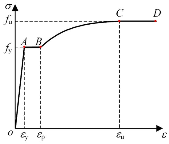
Figure 17.
Steel constitutive model.
Table 5.
Average value of tensile test results.
4.3. Validation of FEM
4.3.1. Failure Mode
The comparison between the numerical and experimental results of the failure modes of OFW-2-100-7 is shown in Figure 18a. It could be observed that the failure modes of the FEMs were similar to the experimental results, such as local buckling at the midspan and local compression deformation at the loading location. After removing unnecessary components, the stress distribution and deformation of the FEMs at the later stage of loading are shown in Figure 19. It could be recognized that the maximum stress occurred in the web and fold-fastened region at the midspan, where the plates experienced significant deformation. The plates in the tensile region near the midspan experienced lower stress. The fold-fastened region at the midspan began to separate. The comparison of OFW-3-100-7 is shown in Figure 18b, which presents good consistency. The stress distribution and deformation of OFW-3-100-7 were similar to OFW-2-100-7, as shown in Figure 20.
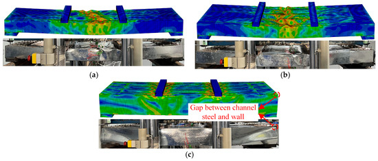
Figure 18.
Comparison of failure modes between FEMs and tests: (a) The comparison of OFW-2-100-7; (b) The comparison of OFW-3-100-7; (c) The comparison of OFW-3-200-10.
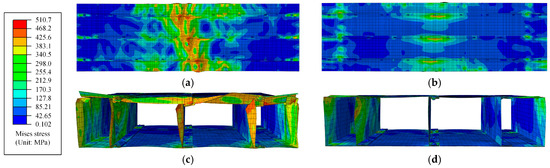
Figure 19.
Stress and deformation distributions of OFW-2-100-7: (a) Top surface; (b) Bottom surface; (c) Cross-section of midspan; (d) Cross-section of loading location.
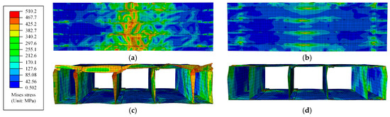
Figure 20.
Stress and deformation distributions of OFW-3-100-7: (a) Top surface; (b) Bottom surface; (c) Cross-section of midspan; (d) Cross-section of loading location.
The comparison between the numerical and experimental results of the failure modes of OFW-3-200-10 is shown in Figure 18c. It could be observed that the failure modes of the FEM were similar to the experimental results, such as local compression deformation at the loading location and local buckling of the flange of the edge channel steel. The stress distribution and deformation of the FEM at the later stage of loading are shown in Figure 21. It could be observed that the maximum stress and deformation in the FEM occurred in the loading location on the top surface, while the stress in the loading region on the bottom surface was relatively lower than that on the top surface but still higher than in other regions. The deformation in the mid-span region was relatively small, and the fold-fastened region remained intact.
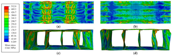
Figure 21.
Stress and deformation distributions of OFW-3-200-10: (a) Top surface; (b) Bottom surface; (c) Cross-section of midspan; (d) Cross-section of loading location.
4.3.2. Bending Moment–Deflection Curves and Flexural Capacities
As shown in Figure 22a–c, the bending moment–deflection curves of the FEM are compared with the experimental results. It could be seen that the overall trend of the curves was consistent. Due to the initial imperfections and assembly errors of the specimens, the bearing capacity of FEMs was higher than the experimental results. As shown in Figure 22d and Table 6, the results indicated that the error between the numerical and experimental results was mostly within ±5%. Additionally, the R2 values exceed 0.98 and the Mean Deviation values are below 5%, indicating an excellent agreement between the numerical and experimental responses.
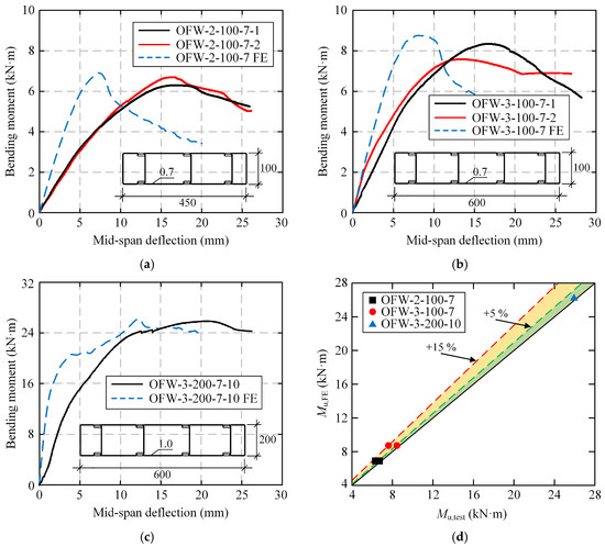
Figure 22.
Comparison of bending moment–deflection curves and flexural bearing capacities between FEMs and tests: (a) OFW-2-100-7; (b) OFW-3-100-7; (c) OFW-3-200-10; (d) Comparison of bearing capacity.
Table 6.
Comparison of flexural bearing capacity between FEMs and tests.
Despite the excellent overall agreement, some potential variability and model uncertainties should be acknowledged. The primary source of variability stems from initial geometric imperfections in the actual specimens, which, although considered in the model, have a complex and stochastic nature. Furthermore, minor assembly gaps and slight variations in the contact conditions are challenging to model with perfect fidelity. These factors are believed to contribute to the slight overestimation of initial stiffness in some FEM predictions. Nonetheless, the excellent agreement in ultimate capacity and failure modes confirms the model’s robustness for strength and parametric studies.
4.4. Parametric Analysis
As shown in Table 7, six sets of numerical examples were established, which were numbered Groups 1–6, respectively, to further study the effect of different design parameters on the flexural behavior of FMSPs and provide valuable reference for practical engineering applications. The elastic modulus E of the steel was 206 GPa, and Poisson’s ratio ν was 0.3.
Table 7.
Details of FEMs in numerical analysis.
4.4.1. Steel Plate Thickness tw and Steel Strength fy
The effects of steel plate thickness tw and steel strength fy on the flexural behavior of FMSPs are described in Figure 23. In Figure 23a, it could be found that as the steel plate thickness increased, the initial stiffness increased significantly. In addition, when the steel plate thickness increased from 0.6 mm to 0.8, 1.0, 1.2, and 1.4 mm, the ultimate flexural capacity increased by 70.33%, 140.93%, 206.72%, and 272.57%, respectively. The enhanced performance with increasing steel plate thickness tw is attributed to two fundamental mechanical principles: (1) improved local buckling resistance due to reduced width-to-thickness ratios, allowing sections to further utilize their material capacity, and (2) increased sectional modulus that directly enhances moment capacity. Therefore, in the practical design of FMSPs, choosing thicker steel plates could yield favorable mechanical performance.
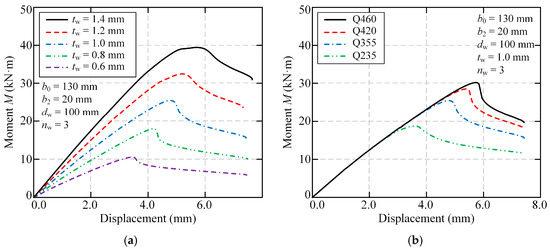
Figure 23.
Effect of steel plate thickness and steel strength on flexural behavior: (a) Group 1: tw; (b) Group 2: fy.
In Figure 23b, it could be observed that the initial stiffness was not influenced by steel strength. In addition, as steel strength increased, the rate of load reduction in the post-peak stage became faster. Additionally, as the steel strength increased from 235 MPa to 355, 420, and 460 MPa, corresponding to an increase of 51.06%, 78.72%, and 95.74%, respectively, the ultimate flexural capacity only increased by 36.02%, 52.06%, and 61.14%, respectively. This suggested that the increase in steel strength yielded a lower benefit in improving ultimate flexural capacity. The diminishing returns from higher steel strength fy result from the strength-stability interaction in thin-walled sections. As material strength increases, local buckling often governs failure before the material yield strength is fully utilized, explaining the sub-proportional capacity gains.
4.4.2. Panel Width
The panel width was determined by the cell number nw, the plate width b0, and the width b2 of fold-fastened regions. From Figure 24a, it could be drawn that when the cell number np increased from 2 to 6, the increments of ultimate flexural capacity were 5.85, 11.20, 17.60, and 22.21 kN·m, respectively. Therefore, it could be concluded that when nw increased, the ultimate flexural capacity increased linearly. The linear relationship between cell number nw and flexural capacity stems from the direct proportionality between additional cells and sectional moment of inertia.
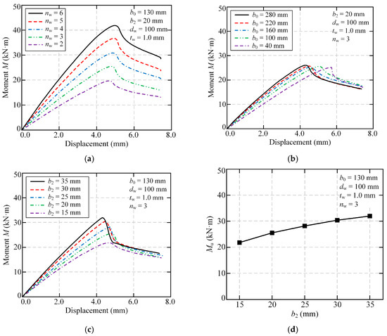
Figure 24.
Effect of panel width on flexural behavior: (a) Group 3: nw; (b) Group 4: b0; (c) Group 5: b2; (d) Group 5: Mu.
As shown in Figure 24b, as the plate width increased from 40 mm to 100, 160, 220, and 280 mm, corresponding to an increase of 150%, 300%, 450%, and 600%, respectively, the ultimate flexural capacity increased by 1.79%, 1.43%, 2.45%, and 3.58%, respectively. It could be observed that the significant increase in plate width has minimal influence on the ultimate flexural capacity of the FMSP. This was because when the panel width increased, the increment in the effective width of the plate was not significant. The minimal effect of plate width b0 expansion reflects the effective width concept in cold-formed steel design, where portions of wide flanges become ineffective due to local buckling.
As shown in Figure 24c, the ultimate flexural capacity increased by 17.07%, 29.22%, 39.43%, and 46.74%, respectively, with the proportional increase in the width of fold-fastened regions, and the increase rate of the ultimate flexural capacity gradually decreased. As shown in Figure 24d, the slope of the line decreased with the increase of b2. The diminishing benefits of wider fold-fastened regions b2 occur because these regions act as elements susceptible to local buckling, limiting their contribution to overall section performance. The impact of this effect would be more pronounced when dealing with thinner steel plates, thus emphasizing the need to avoid excessively wide fold-fastened regions in practical engineering scenarios.
4.4.3. Panel Thickness dw
As shown in Figure 25, as the panel thickness dw increased from 60 mm by 50%, 100%, 150%, and 200% to 90, 120, 150, and 180 mm, the ultimate flexural capacity increased by 64.11%, 123.16%, 181.56%, and 246.18%, respectively. The exceptional effectiveness of increasing panel thickness dw follows from the fundamental bending theory, where section modulus increases with the square of the section height. This mechanical principle explains why panel thickness enhancement provides an efficient means for improving flexural performance in FMSPs.
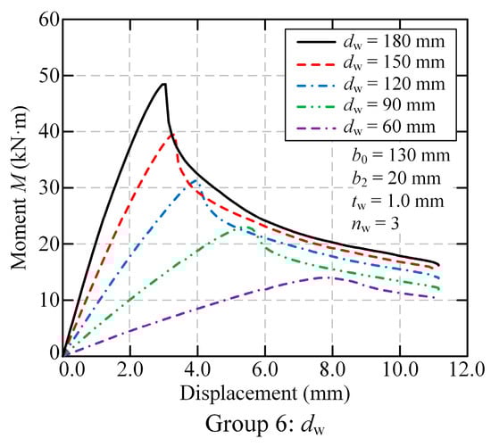
Figure 25.
Effect of panel thickness on flexural behavior.
4.5. Design Implications and Optimization Guidelines
Based on the parametric analysis and underlying mechanical principles, the following design recommendations are proposed for practical FMSP applications:
Priority parameters for flexural capacity optimization: Based on quantified results, the key parameters can be ranked by their effectiveness in enhancing ultimate flexural capacity as follows: increasing the steel plate thickness tw constitutes the primary strategy, being the most influential parameter, owing to the concurrent enhancement of the cross-sectional area and significant improvement in local buckling resistance of all plate components; increasing the panel thickness dw serves as the secondary strategy, providing a substantial 123% improvement upon doubling; finally, increasing the cell number nw represents a tertiary strategy, delivering a near-linear gain in capacity while offering added flexibility for architectural adaptation.
Parameters with limited benefits: In contrast to geometric parameters, modifications to material and connection properties yield progressively diminishing returns: enhancing the yield strength fy provides limited structural benefit and should only be considered after geometric optimization; expanding the flange width b0 offers minimal improvement and should be governed primarily by connection requirements; meanwhile, increasing the fold-fastened region width b2 requires careful optimization for connection integrity rather than indiscriminate enlargement to prevent local buckling.
Practical optimization pathway: For an efficient and cost-effective design process, engineers are recommended to first optimize the steel plate thickness tw to meet the target flexural capacity, as it provides the highest performance gain per unit increase; then adjust the panel thickness dw to further finetune the capacity and stiffness, leveraging its substantial influence; subsequently configure the cell number nw to achieve the required sectional width and accommodate architectural layout needs; and finally select a standard steel grade fy based on material availability and cost-effectiveness, rather than relying on high-strength steel for primary capacity improvements.
5. Conclusions
This study investigated the flexural behavior of FMSPs through integrated experimental and numerical approaches. The main findings are summarized as follows:
- (1)
- Failure patterns: Local compressive deformation developed in the edge cell beneath the loading point, accompanied by local buckling in the upper flange at mid-span. Excessively deep indentations should be avoided as they promote interconnected local buckling patterns. A staggered layout is recommended to mitigate this failure mode.
- (2)
- Structural response: The moment-deflection response exhibited four characteristic stages: linear stage, nonlinear stage, peak load, and descent stage. The FMSPs demonstrated excellent deformation capacity with progressive load development. Flexural capacity and stiffness were enhanced by increasing cell number, panel thickness, and steel plate thickness, with the latter two parameters exhibiting dominant effects.
- (3)
- Parametric analysis: Refined finite element models demonstrated excellent agreement with experimental results in failure modes and flexural capacities. Parametric analysis quantified the superior efficiency of geometric optimization: doubling steel plate thickness increased capacity by 207%, while doubling panel thickness provided a 123% improvement. In contrast, increasing steel strength from 235 MPa to 460 MPa yielded only a 61% enhancement. Cell number exhibited approximately linear correlation with capacity, whereas panel and fold-fastened region widening provided diminishing returns (<4% improvement for 600% width increase). The established design guidelines, which prioritize geometric dimensions over material strength, offer practical optimization strategies for FMSP applications.
- (4)
- Limitations and future research directions: While the numerical models accurately predicted ultimate failure modes and capacities, they systematically overestimated initial stiffness, likely due to simplified boundary conditions and interface modeling. Future work should incorporate advanced and detailed contact definitions, validate key configurations through repeated testing, and investigate FMSP performance under axial compression, combined loading, and extreme conditions to support building code and practical implementation.
Author Contributions
Conceptualization, S.-J.D. and G.-S.T.; methodology, C.-D.Y. and G.-S.T.; validation, L.-Q.G.; formal analysis, S.-J.D.; investigation, S.-J.D. and C.-D.Y.; resources, G.-S.T.; writing—original draft preparation, S.-J.D. and C.-D.Y.; writing—review and editing, S.-J.D. and L.-Q.G.; supervision, G.-S.T.; funding acquisition, G.-S.T. All authors have read and agreed to the published version of the manuscript.
Funding
This research was funded by Zhejiang Provincial Natural Science Foundation of China, Grant no. LZ22E080004.
Data Availability Statement
The original contributions presented in this study are included in the article. Further inquiries can be directed to the corresponding author.
Conflicts of Interest
The authors declare no conflicts of interest.
References
- Wu, R.; Yu, C.; Wang, L.; Tong, J. Shear elastic buckling of corrugated steel plate shear walls with stiffeners considering torsional rigidity. Thin-Walled Struct. 2025, 206, 112646. [Google Scholar] [CrossRef]
- Yu, C.; Tong, J.; Zhou, S.; Zhang, J.; Shen, J.; Zhang, L.; Tong, G.; Li, Q.; Xu, S. State-of-the-art review on steel-concrete composite walls. Sustain. Struct. 2024, 4, 35. [Google Scholar] [CrossRef]
- Chen, Y.; Tong, J.; Li, Q.; Xu, S.; Shen, L. Application of high-performance cementitious composites in steel–concrete composite bridge deck systems: A review. J. Intell. Constr. 2024, 2, 9180012. [Google Scholar] [CrossRef]
- Antonodimitraki, S.; Thanopoulos, P.; Vayas, I. EC3-Compatible Methods for Analysis and Design of Steel Framed Structures. Modelling 2021, 2, 567–590. [Google Scholar] [CrossRef]
- Wang, W.; Wang, J.; Guo, L. Mechanical behavior analysis of LEM-infilled cold-formed steel walls. Sustain. Struct. 2022, 2, 13. [Google Scholar] [CrossRef]
- Wang, L.; Teng, D.; Jin, R.; Guo, X.; Meng, X.; Liu, G.; Luo, X.; Sun, C.; Su, Z. The development of prefabricated buildings and intelligent construction based on digital twins. J. Intell. Constr. 2024, 3, 9180080. [Google Scholar] [CrossRef]
- Moen, C.; Igusa, T.; Schafer, B. Prediction of residual stresses and strains in cold-formed steel members. Thin-Walled Struct. 2008, 46, 1274–1289. [Google Scholar] [CrossRef]
- Li, Z.; Schafer, B. Application of the finite strip method in cold-formed steel member design. J. Constr. Steel Res. 2010, 66, 971–980. [Google Scholar] [CrossRef]
- Ayhan, D.; Schafer, B. Cold-formed steel member bending stiffness prediction. J. Constr. Steel Res. 2015, 115, 148–159. [Google Scholar] [CrossRef]
- Schafer, B. Advances in the Direct Strength Method of cold-formed steel design. Thin-Walled Struct. 2019, 140, 533–541. [Google Scholar] [CrossRef]
- Meng, X.; Gardner, L. Cross-sectional behaviour of cold-formed high strength steel circular hollow sections. Thin-Walled Struct. 2020, 156, 106822. [Google Scholar] [CrossRef]
- Behzadi Sofiani, B.; Gardner, L.; Wadee, M. Testing, simulation and design of steel equal-leg angle section beams. Thin-Walled Struct. 2022, 171, 108698. [Google Scholar] [CrossRef]
- Meng, X.; Gardner, L. Stability and design of normal and high strength steel CHS beam-columns. Eng. Struct. 2022, 251, 113361. [Google Scholar] [CrossRef]
- Wu, Y.; Fan, S.; Du, L.; Wu, Q. Research on distortional buckling capacity of stainless steel lipped C-section beams. Thin-Walled Struct. 2021, 169, 108453. [Google Scholar] [CrossRef]
- Fan, S.; Wu, Y.; Du, L.; Liu, M.; Wu, Q. Experimental study and numerical simulation analysis of distortional buckling capacity of stainless steel lipped C-section beams. Eng. Struct. 2022, 250, 113428. [Google Scholar] [CrossRef]
- Wu, Y.; Fan, S.; Wu, Q.; Liang, D. Experimental study of local—Distortional interaction of press-braked stainless steel lipped channel beams. Eng. Struct. 2023, 280, 115713. [Google Scholar] [CrossRef]
- Liang, D.; Fan, S.; Dong, D.; Liu, M. Experimental investigation of global-distortional interaction buckling of stainless steel C-beams. J. Constr. Steel Res. 2024, 214, 108472. [Google Scholar] [CrossRef]
- Wang, F.; Zhao, O.; Young, B. Flexural behaviour and strengths of press-braked S960 ultra-high strength steel channel section beams. Eng. Struct. 2019, 200, 109735. [Google Scholar] [CrossRef]
- Zhang, L.; Wang, F.; Liang, Y.; Zhao, O. Experimental and numerical studies of press-braked S690 high strength steel channel section beams. Thin-Walled Struct. 2020, 148, 106499. [Google Scholar] [CrossRef]
- Li, L.; Li, H.; Young, B. Cold-formed ferritic stainless steel SHS and RHS beams: Testing, modeling and design. J. Constr. Steel Res. 2022, 197, 107429. [Google Scholar] [CrossRef]
- Zhou, X.; Shi, Y. Flexural Strength Evaluation for Cold-Formed Steel Lip-Reinforced Built-up I-Beams. Adv. Struct. Eng. 2011, 14, 597–611. [Google Scholar] [CrossRef]
- Yao, X.; Zhou, X.; Shi, Y.; Guan, Y.; Zou, Y. Simplified calculation method for flexural moment capacity of cold-formed steel built-up section beams. Adv. Struct. Eng. 2020, 23, 3153–3167. [Google Scholar] [CrossRef]
- Phan, D.; Rasmussen, K. Flexural rigidity of cold-formed steel built-up members. Thin-Walled Struct. 2019, 140, 438–449. [Google Scholar] [CrossRef]
- Chen, B.; Roy, K.; Fang, Z.; Uzzaman, A.; Raftery, G.; Lim, J. Moment capacity of back-to-back cold-formed steel channels with edge-stiffened holes, un-stiffened holes, and plain webs. Eng. Struct. 2021, 235, 112042. [Google Scholar] [CrossRef]
- Roy, K.; Lau, H.; Ting, T.; Chen, B.; Lim, J. Flexural capacity of gapped built-up cold-formed steel channel sections including web stiffeners. J. Constr. Steel Res. 2020, 172, 106154. [Google Scholar] [CrossRef]
- Roy, K.; Ho Lau, H.; Ting, T.; Chen, B.; Lim, J. Flexural behaviour of back-to-back built-up cold-formed steel channel beams: Experiments and finite element modelling. Structures 2021, 29, 235–253. [Google Scholar] [CrossRef]
- Phan, D.; Rasmussen, K.; Schafer, B. Tests and design of built-up section columns. J. Constr. Steel Res. 2021, 181, 106619. [Google Scholar] [CrossRef]
- Phan, D.; Rasmussen, K.; Schafer, B. Numerical investigation of the strength and design of cold-formed steel built-up columns. J. Constr. Steel Res. 2022, 193, 107276. [Google Scholar] [CrossRef]
- Li, Q.; Young, B. Structural performance of cold-formed steel built-up section beams under non-uniform bending. J. Constr. Steel Res. 2022, 189, 107050. [Google Scholar] [CrossRef]
- Wang, L.; Young, B. Beam tests of cold-formed steel built-up sections with web perforations. J. Constr. Steel Res. 2015, 115, 18–33. [Google Scholar] [CrossRef]
- Wang, L.; Young, B. Behavior of Cold-Formed Steel Built-Up Sections with Intermediate Stiffeners under Bending. II: Parametric Study and Design. J. Struct. Eng. 2016, 142, 4015151. [Google Scholar] [CrossRef]
- Wang, L.; Young, B. Behavior of Cold-Formed Steel Built-Up Sections with Intermediate Stiffeners under Bending. I: Tests and Numerical Validation. J. Struct. Eng. 2016, 142, 4015150. [Google Scholar] [CrossRef]
- Serrette, R. Performance of edge-loaded cold-formed steel built-up box beams. Pract. Period. Struct. Des. Constr. 2004, 9, 170–174. [Google Scholar] [CrossRef]
- Xu, L.; Sultana, P.; Zhou, X. Flexural strength of cold-formed steel built-up box sections. Thin Wall. Struct. 2009, 47, 807–815. [Google Scholar] [CrossRef]
- Li, Y.; Li, Y.; Shen, Z. Investigation on flexural strength of cold-formed thin-walled steel beams with built-up box section. Thin-Walled Struct. 2016, 107, 66–79. [Google Scholar] [CrossRef]
- Selvaraj, S.; Madhavan, M. Structural Design of Cold-formed Steel face-to-face Connected Built-up beams using Direct Strength Method. J. Constr. Steel Res. 2019, 160, 613–628. [Google Scholar] [CrossRef]
- Anbarasu, M. Simulation of flexural behaviour and design of cold-formed steel closed built-up beams composed of two sigma sections for local buckling. Eng. Struct. 2019, 191, 549–562. [Google Scholar] [CrossRef]
- Karthik, C.; Anbarasu, M. Cold-formed ferritic stainless steel closed built-up beams: Flexural behaviour and numerical parametric study. Thin-Walled Struct. 2021, 164, 107816. [Google Scholar] [CrossRef]
- Karthik, C.; Anbarasu, M.; Dar, M. Cold-formed ferritic stainless steel closed-section built-up beams: Tests and flexural response. Thin-Walled Struct. 2022, 180, 109820. [Google Scholar] [CrossRef]
- Yang, X.; Tong, J.; Yu, C.; Duan, S.; Tong, G.; Jiang, J. Numerical analysis on global stability performance of fold-fastened multi-cellular steel walls. J. Build Eng. 2024, 88, 109168. [Google Scholar] [CrossRef]
- Duan, S.; Tong, J.; Yu, C.; Yang, X.; Tong, G. Axial resistant behavior of stub fold-fastened multi-cellular steel walls: Tests and simulations. J. Build Eng. 2025, 108, 112913. [Google Scholar] [CrossRef]
- Tong, J.; Duan, S.; Yang, X.; Yu, C.; Tong, G. Stability tests and simulations of fold-fastened multi-cellular steel walls. Int. J. Struct Stab. Dyn. 2024, 25, 2550103. [Google Scholar] [CrossRef]
- Chandrasiri, D.; Gatheeshgar, P.; Ahmadi, H.; Simwanda, L. Numerical Study of Thermal Efficiency in Light-Gauge Steel Panels Designed with Varying Insulation Ratios. Buildings 2024, 14, 300. [Google Scholar] [CrossRef]
- Simwanda, L.; Gatheeshgar, P.; Ilunga, F.; Ikotun, B.; Mojtabaei, S.; Onyari, E. Explainable machine learning models for predicting the ultimate bending capacity of slotted perforated cold-formed steel beams under distortional buckling. Thin-Walled Struct. 2024, 205, 112587. [Google Scholar] [CrossRef]
- Simwanda, L.; Gatheeshgar, P.; Sykora, M.; Sejkot, P.; David, A.; Olalusi, O. Local buckling strength prediction of slotted cold-formed steel beams using ensemble learning. J. Constr. Steel Res. 2026, 236, 110024. [Google Scholar] [CrossRef]
- GB/T 2518-2019; Continuously Hot-Dip Zinc and Zinc Alloy Coated Steel Sheet and Strip. Standardization Administration of the People’s Republic of China: Beijing, China; Standards Press of China: Beijing, China, 2019.
- GB 50205-2020; Standard for Acceptance of Construction Quality of Steel Structures. Ministry of Housing and Urban-Rural Development of the People’s Republic of China: Beijing, China; China Planning Press: Beijing, China, 2020.
- Tong, J.; Chen, Y.; Li, Q.; Dai, J.; Wang, G.; Shen, J.; Gao, W.; Xu, S. Flexural performance and crack width prediction of steel-UHTCC composite bridge decks with wet joints. Eng. Struct. 2025, 323, 119264. [Google Scholar] [CrossRef]
- Yu, C.; Tong, J.; Zhang, J.; Tong, G.; Chen, M.; Xu, S.; Gao, W. Axial compressive behavior of multi-celled corrugated-plate CFST walls: Tests and numerical simulations. Eng. Struct. 2025, 322, 119033. [Google Scholar] [CrossRef]
- GB/T 228.1-2021; Metallic Materials-Tensile Testing-Part 1: Method of Test at Room Temperature. Standardization Administration of the People’s Republic of China: Beijing, China; Standards Press of China: Beijing, China, 2021.
- Yu, C.; Duan, S.; Tong, J. Global buckling simulation and design of a novel concrete-filled corrugated steel tubular column. Modelling 2025, 6, 22. [Google Scholar] [CrossRef]
- Tong, J.; Wang, L.; Wu, R.; Hou, J.; Li, Q.; Xu, S. Cyclic test and analysis of UHTCC-enhanced buckling-restrained steel plate shear walls. Earthq. Eng. Struct. D 2024, 53, 4006–4031. [Google Scholar] [CrossRef]
- Chen, Y.; Tong, J.; Li, Q.; Zhang, E.; Gao, W.; Xu, S. Local instability and interactive mechanism analysis of UHTCC-encased rectangular steel tubular columns. J. Constr. Steel Res. 2025, 228, 109444. [Google Scholar] [CrossRef]
- Zhang, J.; Tong, G.; Tong, J. Global buckling prevention of multi-celled corrugated-plate CFST walls under pure in-plane bending loads. Eng. Struct. 2025, 332, 120061. [Google Scholar] [CrossRef]
- Rahnavard, R.; Razavi, M.; Fanaie, N.; Craveiro, H.D. Evaluation of the composite action of cold-formed steel built-up battened columns composed of two sigma-shaped sections. Thin-Walled Struct. 2023, 183, 110390. [Google Scholar] [CrossRef]
- Mojtabaei, S.; Becque, J.; Hajirasouliha, I. Local Buckling in Cold-Formed Steel Moment-Resisting Bolted Connections: Behavior, Capacity, and Design. J. Struct. Eng. 2020, 146, 4020167. [Google Scholar] [CrossRef]
- Samiee, P.; Esmaeili Niari, S.; Ghandi, E. Thermal and structural behavior of cold-formed steel frame wall under fire condition. Eng. Struct. 2022, 252, 113563. [Google Scholar] [CrossRef]
- Schafer, B.; Peköz, T. Computational modeling of cold-formed steel: Characterizing geometric imperfections and residual stresses. J. Constr. Steel Res. 1998, 47, 193–210. [Google Scholar] [CrossRef]
- Young, B.; Rasmussen, K. Tests of Fixed-Ended Plain Channel Columns. J. Struct. Eng. 1998, 124, 131–139. [Google Scholar] [CrossRef]
- Tao, Z.; Wang, Z.; Yu, Q. Finite element modelling of concrete-filled steel stub columns under axial compression. J. Constr. Steel Res. 2013, 89, 121–131. [Google Scholar] [CrossRef]
Disclaimer/Publisher’s Note: The statements, opinions and data contained in all publications are solely those of the individual author(s) and contributor(s) and not of MDPI and/or the editor(s). MDPI and/or the editor(s) disclaim responsibility for any injury to people or property resulting from any ideas, methods, instructions or products referred to in the content. |
© 2025 by the authors. Licensee MDPI, Basel, Switzerland. This article is an open access article distributed under the terms and conditions of the Creative Commons Attribution (CC BY) license (https://creativecommons.org/licenses/by/4.0/).