1. Introduction
Reinforced concrete (RC) walls, as key load-bearing and protective components in buildings, are highly susceptible to brittle failure under explosive loads, including cracking, spalling, and overall instability [
1,
2,
3]. These failures pose a serious threat to both structural integrity and personnel safety. With the increasing risk of explosions in modern urban and industrial environments [
4], improving the blast resistance of RC walls has become a core research direction in the field of protective engineering and structural safety in response to major challenges [
5,
6].
Current research on improving the blast resistance of RC walls primarily follows two technical approaches: material enhancement and structural innovation. In terms of material strengthening, the traditional strategies for improving the blast resistance of RC walls usually mainly include increasing the thickness of the components, using higher grades of concrete, and increasing the reinforcement ratio [
7,
8,
9]. Lin et al. [
10] conducted numerical simulations to study the effects of panel thickness and reinforcement ratio on the explosive performance of reinforced concrete panels. Yao Shujian et al. [
11] analyzed the blast resistance and damage characteristics of reinforced concrete slabs under different reinforcement ratios through explosion tests and numerical simulations. These methods can improve the load-bearing capacity and ductility of structures to a certain extent. However, they often lead to increased self-weight and higher construction costs. Furthermore, under the action of strong explosive loads, the structure may still suffer brittle failure. To transcend these constraints, investigators have turned their attention to High-Performance Fiber-Reinforced Polymer (HPFRP) [
12]. Materials such as steel fiber [
13,
14], glass fiber [
15], and carbon fiber cloth (CFRP) [
16] exhibit outstanding performance in improving structural ductility, inhibiting crack propagation, and enhancing energy absorption capacity. With respect to the blast resistance of fiber-reinforced concrete slabs, numerous scholars have conducted extensive theoretical studies, experimental validations, and numerical simulations [
17,
18]. Ngo Tuan et al. [
19] focused on the blast resistance of ultrahigh-strength concrete (UHSC) slabs, and the experimental results showed that 100 mm-thick UHSC slabs exhibited significant blast resistance. Mao Lei et al. [
20] carried out a numerical study on the behavior of UHPFRC under blast loading and analyzed the effects of reinforcement bars and steel fibers on enhancing its blast resistance. The above-mentioned fiber materials are effective in improving the ductility and blast resistance of structures. Nevertheless, issues such as high cost, complex construction techniques, and non-uniform fiber distribution have partially constrained their practical engineering application and broader utilization [
21,
22]. Moreover, these studies primarily focus on optimizing material properties while giving insufficient consideration to the modulation of blast wave propagation, thereby limiting their overall protective effectiveness.
Regarding structural innovations, researchers have developed various novel protective systems, such as steel–concrete–steel walls (SCS) [
23], reinforced concrete sandwiched panels [
24], reinforced concrete panel using foam cladding [
25], and fence-type blast wall [
26,
27,
28]. These structures typically induce the reflection and prolongation of shock waves through cavities or interlayers to achieve energy dissipation. Although these studies have, to some extent, improved the blast resistance of RC walls, issues such as excessive self-weight, limited energy-dissipation capacity, and inadequate applicability persist.
In summary, existing research shows limitations in both material and structural dimensions: conventional materials and structures struggle to balance lightweight design with efficient energy dissipation, whereas new material systems lack innovative structural configurations that can fully unlock their potential. Therefore, exploring novel protection systems that combine lightweight design, high strength, and efficient energy-dissipation capacity has become an urgent research need. UHMWPE fiber materials have garnered widespread attention in protective engineering owing to their high specific strength, high toughness, and excellent impact resistance [
29,
30,
31,
32]. Under blast loading, UHMWPE composite materials can markedly attenuate shock-wave transmission, delay crack propagation, and significantly enhance structural toughness and energy-dissipation capacity [
33,
34]. Meanwhile, cavity protection structures achieve multi-stage attenuation through the dispersion and reflection of shock waves, effectively mitigating blast-energy-induced damage to the primary structure [
35]. Nevertheless, the coupling mechanism between the exceptional toughness of UHMWPE and cavity wave modulation has not yet been thoroughly investigated in current research.
Building on the preceding context, this study integrates the synergistic integration of the dynamic energy dissipation characteristics of UHMWPE material with the wave modulation mechanism of cavity structures, thereby proposing a novel UHMWPE cavity protective panel. The dynamic response and blast resistance of the structure under near-field blast loading are investigated via numerical simulations using the LS-DYNA finite-element program. This study focuses on blast-wave decay characteristics, wall damage patterns, and energy-dissipation behavior, and performs parametric analyses to refine critical design variables, including the thicknesses of the front and rear panels, cavity geometry, and rib configuration. This study aims to provide a novel solution to overcome the bottleneck of existing protective technologies and to offer a solid theoretical basis and engineering reference for the high-performance protection design of RC walls. In subsequent work, the dynamic response of the UHMWPE cavity-based protective panel under combined loading from blast overpressure and fragment impact will be investigated.
2. UHMWPE Cavity Protection Structure and Finite-Element Model
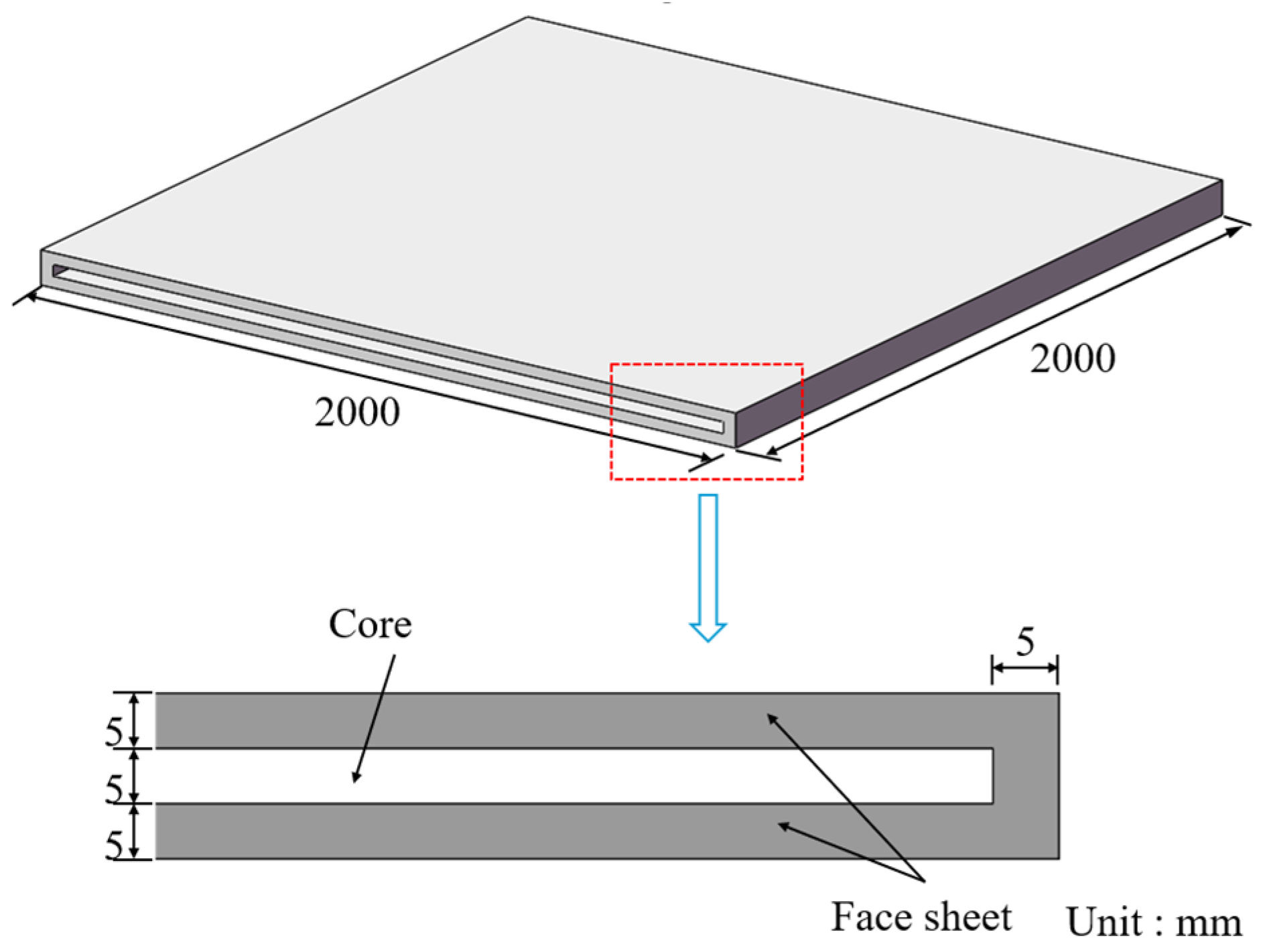
The UHMWPE fiber panel was designed as a double-layer thin plate structure with a cavity. This cavity effectively attenuated the overpressure and suppressed the development of the shockwave under the action of the explosion shockwaves. The configuration and dimensions of the protection panel are illustrated in
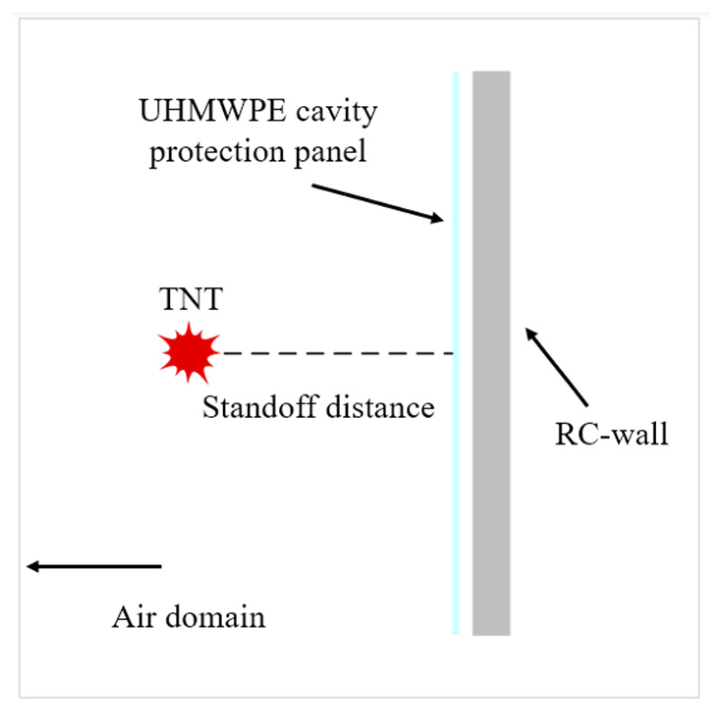
Figure 1. The UHMWPE protection panel measures 2000 mm × 2000 mm × 15 mm in overall size, with both the front and back face layers having a thickness of 5 mm. The internal cavity region has a thickness of 5 mm, resulting in a rectangular frame-like cross-sectional geometry. This study investigates the influence of external protective structures on the blast resistance performance of reinforced concrete walls. The wall specimen measures 2000 mm × 2000 mm × 240 mm. The specimen were reinforced with steel bars with a yield strength of 235 MPa and a diameter of 10 mm. Each reinforcing bar had a length of 1800 mm and was spaced at 300 mm intervals. A clear cover thickness of 35 mm is maintained for the reinforcement. To elucidate the blast mitigation mechanism of the cavity protection panel, the standoff distance between the panel and the reinforced concrete wall was set to 100 mm. Furthermore, the entire model was enclosed within an air domain. To reduce computational cost and avoid simulating nonessential air elements, the dimensions of this air domain were adjusted accordingly based on the equivalent explosive mass and the standoff distance. A schematic diagram of the blast-resistant wall with the cavity protection panel is shown in
Figure 2.
2.1. Finite-Element Modeling and Validation
Numerical modeling based on LS-DYNA is an effective way to obtain a more accurate description of the stress distribution and propagation law of waves. In this study, a three-dimensional finite-element model was established using LS-DYNA R11.1 explicit dynamic analysis software to simulate the dynamic response of the cavity protection structure and reinforced concrete wall under explosive loading. The SOLID164 element is an eight-node explicit solid element suitable for simulating complex nonlinear dynamic behaviors, including large deformations, high strain rates, and material failure under blast and impact loading. Based on these properties, the UHMWPE cavity protection slab and RC wall adopted SOLID164 elements in the simulation. TNT is controlled by volume, with a density of 1.73 g/cm
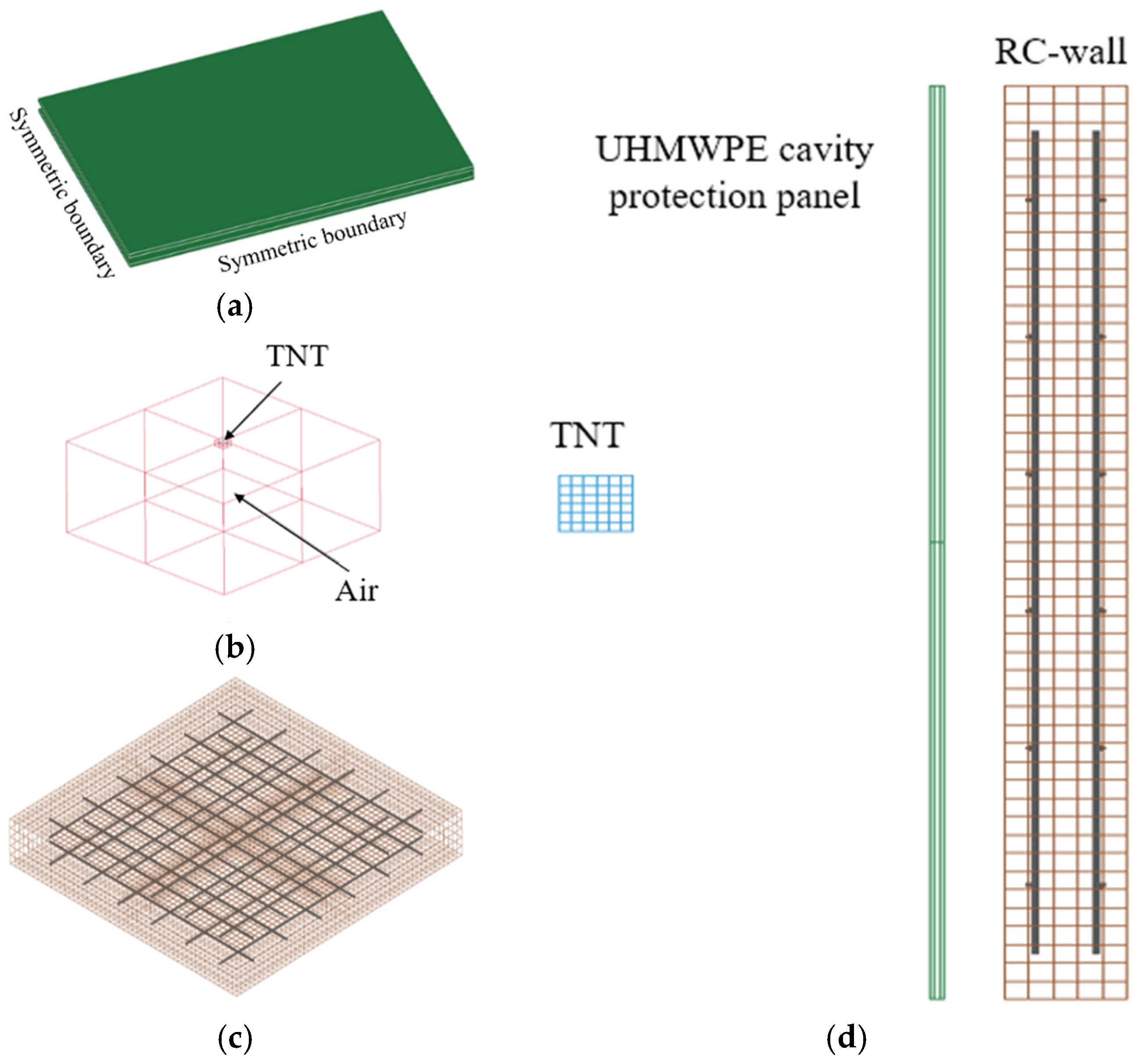
3. Taking 1730 g of TNT equivalent as an example, its corresponding dimensions are a 100 mm × 100 mm × 100 mm cube. To emulate an unbounded domain, non-reflecting (NR) boundary conditions were imposed on the air domain on all sides except the bottom surface and the symmetry boundaries. The entire model was enclosed by an air domain, and TNT was positioned a certain distance in front of the cavity protection structure. To reduce the consumption of computational resources, the air domain size is adjusted based on the TNT equivalent and the standoff distance to eliminate ineffective air elements. As shown in
Figure 3, a 1/4 model has been built, setting symmetric boundaries along the
xz plane and
yz plane.
In the simulation, the ALE algorithm was used for air and TNT, and the LAGRANGE algorithm was used for UHMWPE cavity protection panel and the RC wall. Fluid–structure interaction is built between ALE materials and LAGRANGE materials, to realize pressure propagation in the medium, where the energy is transferred from the explosive to the air through the co-node method. Air and TNT are modeled by ALE elements, which can effectively simulate the propagation of the shockwave. The protective plate and the reinforced concrete wall are simulated using Lagrangian elements, which accurately reflect the dynamic response of the structure. In the LS-DYNA, the card of “CONSTRAINED_LAGRANGE_IN_SOLID” provides a coupling mechanism to model the fluid–structure interaction. Fluid–structure interaction calculation adopts the method of the penalty function. The penalty-function method permits the flow field to move around the structure and prevents fluid–structure interpenetration by applying an interfacial penalty force.
An eroding contact algorithm was applied between the protective plate and the concrete wall to simulate potential material failure and penetration. Furthermore, the simulation controls the sand clock and adjusts other necessary parameters to ensure accuracy. The time step factor is set to 0.4, based on the characteristics of the explosion shock problem, to maintain the stability of the computation process.
2.2. Material Model
2.2.1. Material Model of Concrete
In the study of concrete explosion and other high-strain-rate problems, commonly used models include the JHC model [
36], RHT model, BRITTLE model [
37], and KC model [
38], among others. In this study, MAT_JOHNSON_HOLMQUIST_CONCRETE (MAT 111) in LS-DYNA is selected to model the concrete material. The model is widely applied in the study of concrete’s resistance to explosive impact due to its excellent response to large deformations and high strain rates, making it particularly suitable for fluid–structure coupling problems [
39]. The equivalent stress of this model, after considering the strain rate, can be expressed as:
where
is the ratio of the actual equivalent stress to the static yield strength;
is the dimensionless pressure;
is the dimensionless strain rate;
A,
B,
C, and
N are material constants; and
D (0 ≤
D ≤ 1) is the damage factor, which is obtained by accumulating the equivalent plastic strain and plastic volumetric strain. The parameters of the concrete are presented in
Table 1.
2.2.2. Material Model of Rebar
The MAT_PLASTIC_KINEMATIC model is used for the reinforcement bar. This model is suitable for describing isotropic hardening and rate-dependent kinematic hardening under strain rate effects. The strain rate is typically described using the Cowper–Symonds model. A strain rate-dependent function is added to influence the yield strength. The stress–strain relationship is:
where
P and
C are the parameters related to the strain rate. The parameters of the rebar are presented in
Table 2.
2.2.3. Material Model of UHMWPE
MAT_COMPOSITE_DAMAGE (MAT 22) in LS-DYNA is applied for the UHMWPE cavity protection panel. This model captures the overall mechanical properties of the fiber material by considering the Young’s modulus of both the fiber and matrix materials in different directions, which makes it suitable for describing the failure characteristics of various types of fiber composite laminates under high-speed impact and high strain rate conditions. The parameters of UHMWPE are presented in
Table 3.
2.2.4. Material Model for Air and Explosive
In this study, air is considered an ideal gas. Material model MAT 9 (MAT NULL) is adopted to model the air, with EOS_LINEAR_POLYNOMIAL state equation. The linear polynomial equation of state is:
where
is the pressure,
is the internal energy per unit volume,
is the relative volume, and the initial value is
. For the ideal gas, the coefficients are set as
, and the air parameters are shown in
Table 4.
The explosive material is modeled using MAT_HIGH_EXPLOSIVE_BURN, along with the JWL equation of state. The JWL equation of state is:
where
is the detonation pressure;
V is the relative volume;
E is the internal energy per unit volume; and
,
,
,
, and
are the material-related parameters, with their specific meanings and values given in
Table 5.
2.3. Numerical Methods and Material Model Verification
In this paper, a step-by-step validation method is used to verify the accuracy of the numerical simulation system. Due to the relatively limited research on UHMWPE protection structures for RC walls under explosive loading, this paper sequentially validated the explosion simulation method, concrete constitutive model, and UHMWPE material model. Initially, the accuracy of the explosion simulation method and the concrete constitutive model is validated based on the concrete explosion tests in reference [
40]. Then, the applicability of the material model of UHMWPE under high-strain-rate impact conditions is verified using the fragment penetration tests of UHMWPE fiber laminates from reference [
41]. This validation strategy provided a reliable foundation for the subsequent simulation studies of UHMWPE protection structures for RC walls under explosive loading.
2.3.1. Numerical Methods and Concrete Model Validation
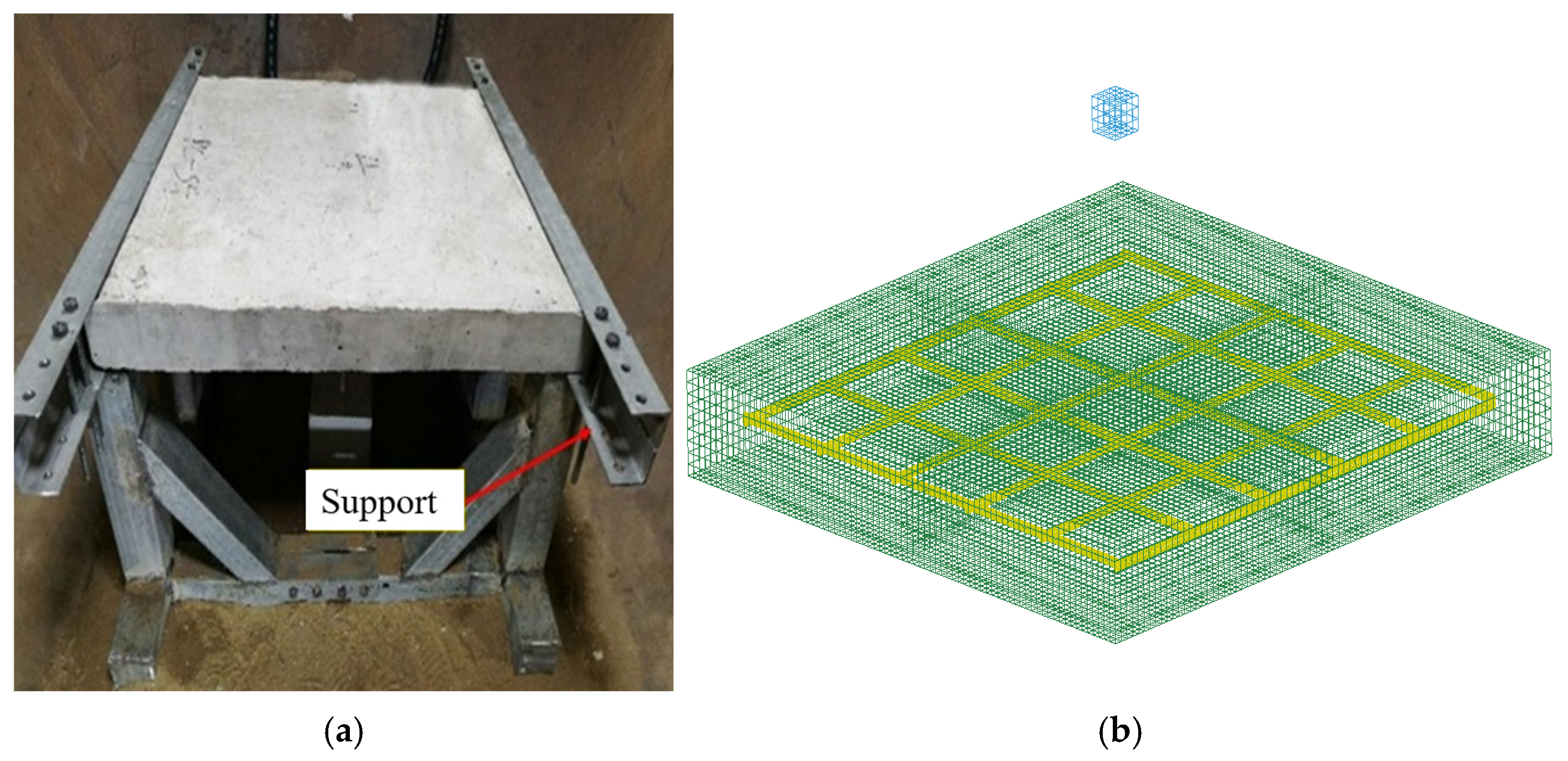
The finite-element model (FEM) and simulation method were validated for accuracy and reliability through the explosion test of the RC panel [
40], as illustrated in
Figure 4. The RC panel in the experiment has geometric dimensions of 750 mm × 850 mm × 90 mm (length × width × thickness). Steel braces are used to support the RC panel, with the two opposite edges of the RC specimen fixed by supports and the other two edges left free, as shown in
Figure 3. The reinforcement bars in the RC panel have a diameter of 8 mm, with a spacing of 130 mm between each bar. In addition, the specimens are placed in a sealed explosion chamber for testing, with the explosive suspended directly above the center of the panel. Each specimen undergoes 10 explosion tests. In this paper, three typical tests are selected for analysis, and the explosive charge and detonation point distances of TNT are shown in
Table 6. The yield strength and elastic modulus of the reinforcement are 235 MPa and 200 GPa, respectively. The compressive strength and elastic modulus of the concrete are 30 MPa, 4.3 MPa, and 30 GPa, respectively. A finite-element model consistent with the experimental conditions is established based on the simulation methods and modeling strategies discussed earlier, as shown in
Figure 4b.
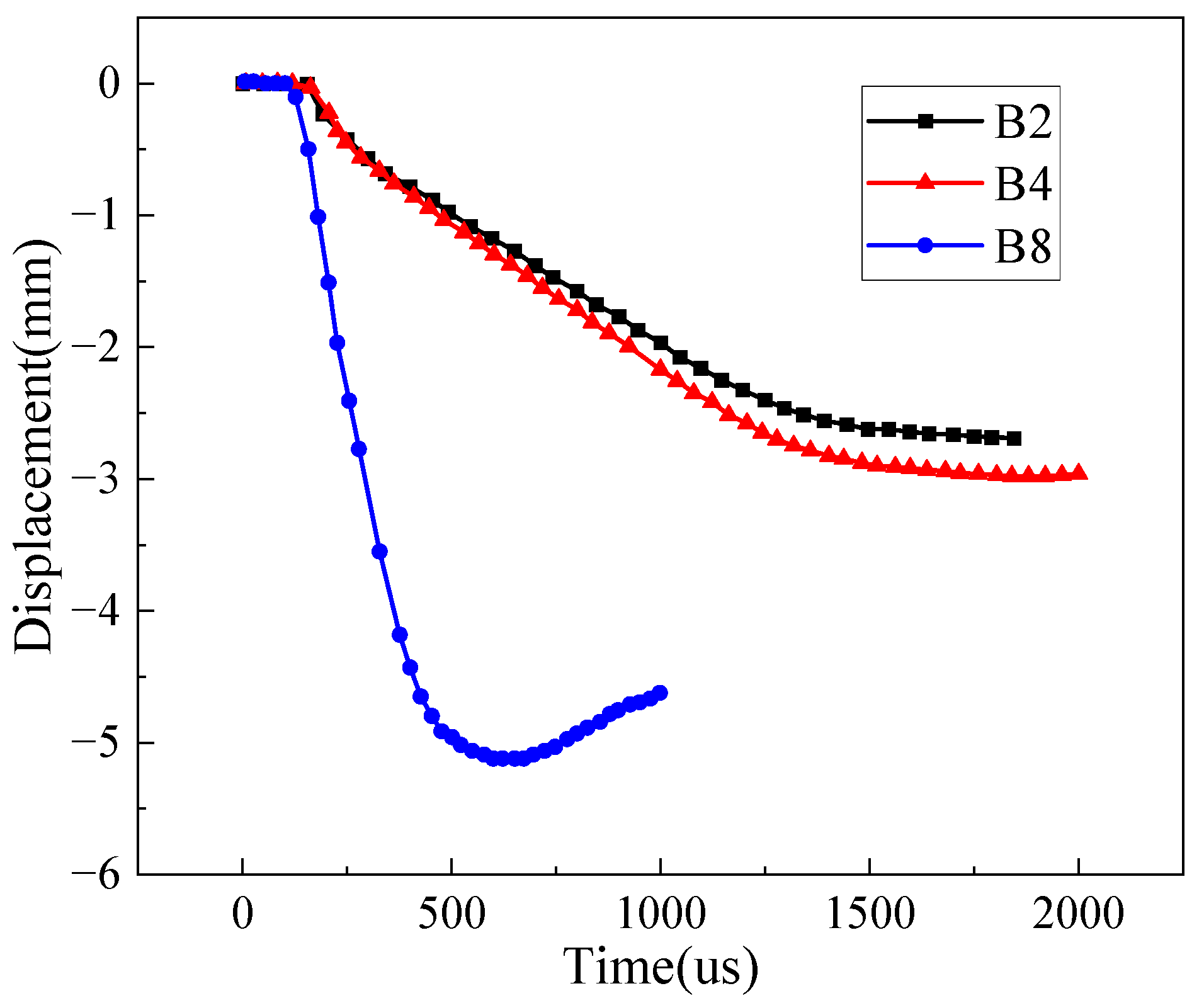
In this paper, the dynamic response of the RC panel under three typical operating conditions was numerically simulated and compared with experimental results, and the accuracy and reliability of the model were evaluated.
Figure 5 presents the displacement–time history curve at the center of the panel for different conditions. The simulated and experimental values of the maximum displacement under each condition are listed in
Table 6. The comparison results indicate that the absolute errors between the simulated and experimental values of the maximum displacement for each condition are kept within a small range, with the maximum error being 1.32 mm, demonstrating good computational precision. Notably, despite the relatively small explosive charge used in the experiment, which caused the displacement response at the center of the panel to be generally lower, the simulation results still demonstrate good consistency with the measured data. This phenomenon suggests that the adopted JHC constitutive model is capable of effectively representing the dynamic response characteristics of concrete under explosive loading. The good agreement between the finite-element simulation results and experimental data also demonstrates the high accuracy and reliability of the finite-element analysis method established in this paper for simulating the explosive response of concrete structures.
2.3.2. UHMWPE Model Validation
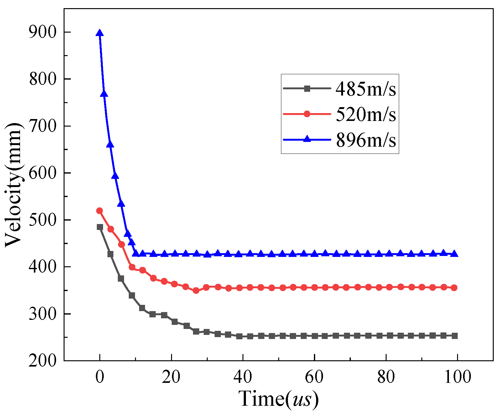
This paper conducted numerical simulations of the UHMWPE fiber laminate fragment penetration tests, validating the accuracy of the constitutive model for UHMWPE under high-strain-rate conditions. Multiple ballistic impacts on the UHMWPE fiber laminates are performed using cubic tool steel projectiles (with a side length of 7.5 mm and a weight of 3.3 g) in the experiment. In the simulation, MAT_PLASTIC_KINEMATIC (Mat 3) is selected as the projectile material, and the specific parameters are provided in
Table 7. The specimen consists of a layered protection panel made from ultra-high-molecular-weight polyethylene (UHMWPE) fiber nonwoven fabric, with a single-layer thickness of 0.16 mm, a total thickness of 4.8 mm, comprising 30 layers, and fixed boundary conditions around the edges. In the simulation, the projectile and the target plate were discretized using SOLID164 solid elements, and automatic surface-to-surface contact was defined between them. To improve computational efficiency, a 1/4 finite-element model is established, and symmetric boundary conditions are applied.
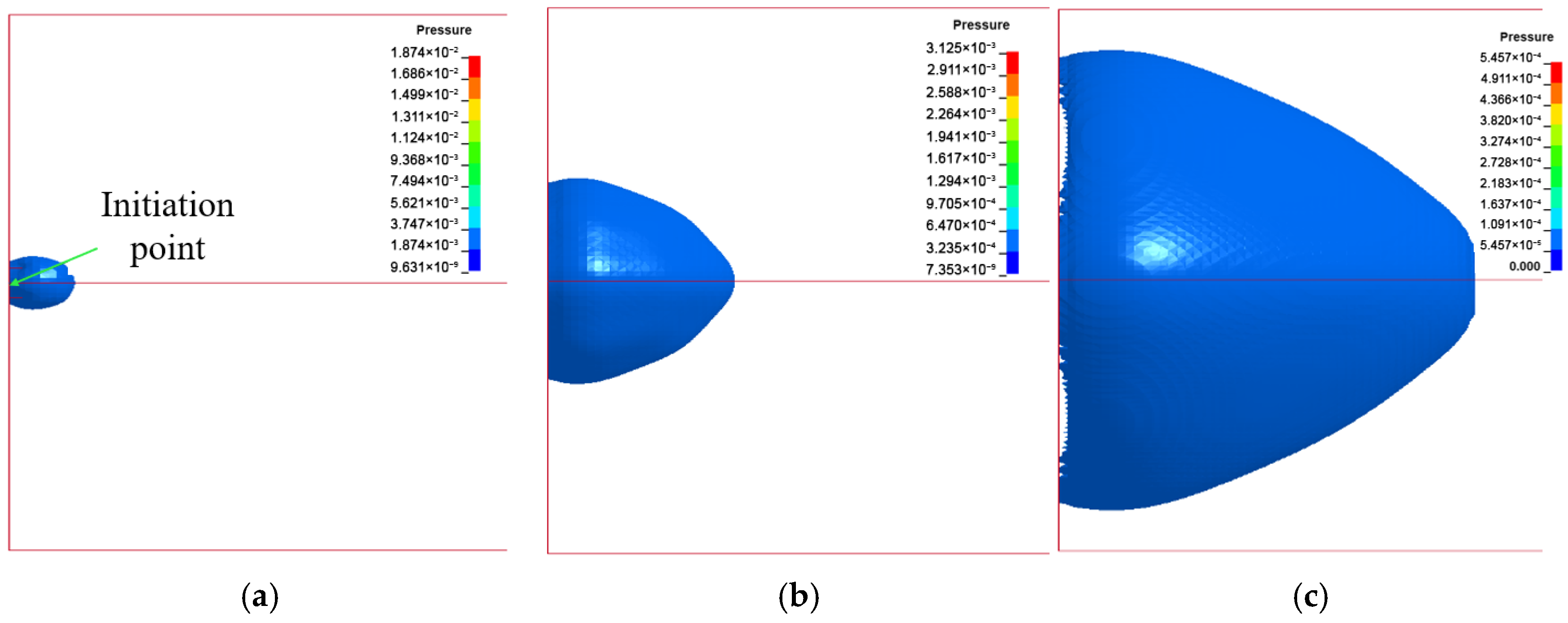
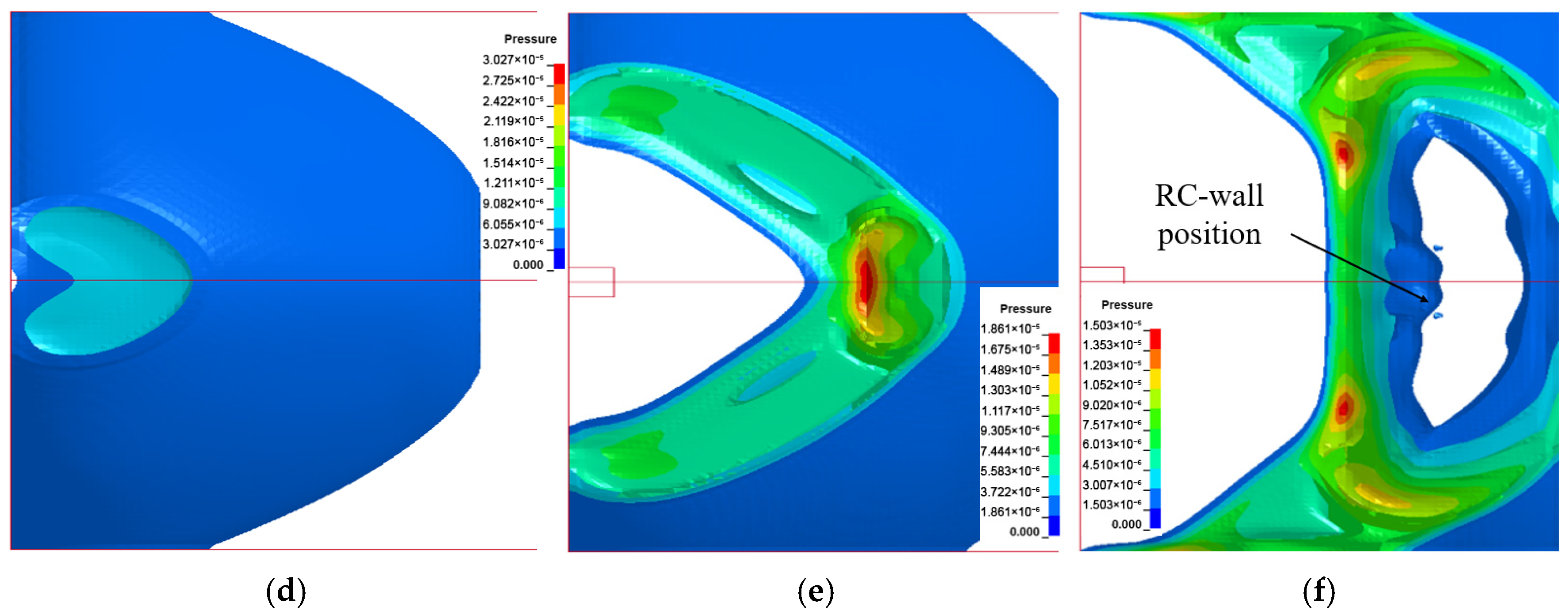
Figure 6 illustrates the damage patterns of the target plate at different times under an initial velocity of 520 m/s, providing a clear view of the penetration process and the dynamic response of the laminate.
Figure 7 shows the velocity–time history curves of the projectile under different initial velocity conditions, and the comparison of the exit velocity with experimental data is provided in
Table 8. The results show that the experimental values of the projectile’s residual velocity match well with the simulated values, with a maximum relative error of 10.3%. It is shown that the MAT_COMPOSITE_DAMAGE model effectively captures the dynamic response behavior of the UHMWPE protection plate under high-strain-rate impacts, offering strong engineering prediction accuracy.






_Su.png)


